Loading ...
Loading ...
Loading ...
First Steps
AIR SPACE
Installation
FL_RC LE_/ELING FEET
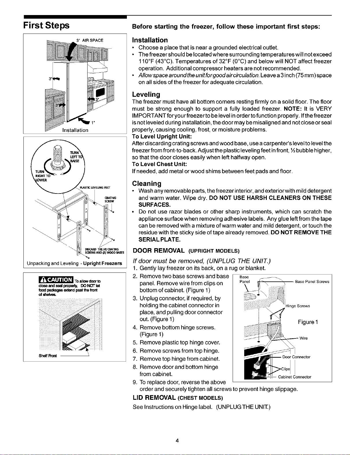
UnpackingandLeveling-Upright Freezers
clo_ and sQalpml_r _ CO NOT let
food packages eadendpastthe front
of shdve_
Shelf Front 1
Before starting the freezer, follow these important first steps:
Installation
• Choose a place that is near a grounded electrical outlet.
• The freezer should be located where surrounding temperatureswill not exceed
110°F (43°C). Temperatures of 32°F (0°C) and below will NOT affect freezer
operation. Additional compressor heaters are not recommended.
• AIIowspacearoundtheunitforgoodaircirculation.Leavea3inch(75mm)space
on all sides of the freezer for adequate circulation.
Leveling
The freezer must have all bottom corners restingfirmly on a solid floor The floor
must be strong enough to support a fully loaded freezer. NOTE: It is VERY
IMPORTANT for yourfreezer to be levelinorder tofunction properly.Ifthe freezer
isnot leveled duringinstallatioin,the door may bemisaligned and notclose orseal
properly, causing cooling, frost, or moisture problems.
To Level Upright Unit:
After discardingcrating screwsand wood base, usea carpenter's levelto levelthe
freezer from front-to-back. Adjust theplasticlevelingfeet infront, ½ bubblehigher,
so thatthe door closes easily when left halfway open.
To Level Chest Unit:
If needed, add metal or wood shims between feet pads and floor
Cleaning
• Washanyremovableparts, thefreezerinterior, andexteriorwithmilddetergent
and warm water. Wipe dry. DO NOT USE HARSH CLEANERS ON THESE
SURFACES.
• Do not use razor blades or other sharp instruments, which can scratch the
appliance surface when removing adhesive labels Any glue leftfrom the tape
can be removed with a mixtureofwarm water and milddetergent, or touchthe
residue with the stickyside oftape already removed. DO NOT REMOVE THE
SERIAL PLATE.
DOOR REMOVAL (UPRIGHT MODELS)
If door must be removed, (UNPLUG THE UNIT.)
1. Gently lay freezer on its back, on a ru! or blanket.
2. Remove two base screws and base Base
panel. Remove wire from clips on Panel
bottom of cabinet. (Figure 1) _-
3. Unplug connector, ifrequired, by
holding the cabinet connector in
place, and pulling door connector
out. (Figure 1)
4. Remove bottom hinge screws.
(Figure 1)
5. Remove plastic top hinge cover.
6. Remove screws from top hinge.
7. Remove top hinge from cabinet.
8. Remove door and bottom hinge
from cabinet.
9. To replace door, reverse the above
order and securely tighten all screws to prevent hinge slippage.
LID REMOVAL (CHEST MODELS)
See Instructions on Hinge label. (UNPLUG THE UNIT.)
Base Panel Screws
4inge Screws
Figure 1
Cabinet Connector
4
Loading ...
Loading ...
Loading ...