
Statement ............................................................ 1
Safety Statement ..................................... 1
Safety Instructions ................................... 2
Safety Operation Specifications ............. 3
Safety Symbols ........................................ 6
Overview .............................................................. 7
Meter panel ............................................... 8
Auto power off ........................................ 10
Fuse burn out prompt ............................ 10
The probe Wrong prompt ...................... 10
Measurement operation ................................... 11
SMART measurement ........................... 11
DC/AC mV measurement ..................... 13
Frequency/Duty measurement ............. 14
Capacitance measurement................... 14
Diode test ................................................ 15
DC/AC current measurement ............... 16
NCV Detection ....................................... 17
Live test ................................................... 18
General technical .............................................. 19
Accuracy ............................................................ 21

DC voltage .............................................. 21
AC voltage .............................................. 22
DC current .............................................. 22
AC current............................................... 23
Diode & Continuity ................................. 23
Resistance .............................................. 24
Capacitance............................................ 24
Frequency/Duty ...................................... 25
Maintain ............................................................. 26
Clean ....................................................... 26
Replace battery or fuse ......................... 27

1
Statement
In accordance with the international copyright law,
without permission and written consent, do not
copy the contents of this manual in any form
(including storage and retrieval or translation into
languages of other countries or regions).
Safety Statement
“Caution” mark refers to the condition and
operation which may cause damage to the
instrument or equipment.
It requires that you must be careful during
the execution of the operation. If incorrectly
perform the operation or do not follow the
procedure, it may damage the instrument or
equipment. In the circumstances that such
conditions are not met or not fully understood,
please do not continue to perform any operation

2
indicated by the caution mark.
“Warning” mark indicates the condition and
operation which may cause danger to users.
It requires that you must pay attention
during the execution of this operation. If
incorrectly perform the operation or do not follow
the procedure, it may result in personal injury or
casualties. In the circumstances that such
conditions are not met or not fully understood,
please do not continue to perform any operation
indicated by the warning mark.
Safety Instructions
This meter conforms to iec61010-1 international
electrical safety standard. The design and
manufacture of instruments shall strictly comply
with iec61010-1 CAT.III 600V safety standard
and pollution level 2.

3
Safety Operation Specifications
WARNNING
In order to avoid possible electric shock or
personal injury and other safety accidents,
please abide by the following specifications:
Please read this manual carefully before using
the instrument.
Strictly observe the operation of this manual
and use this instrument. Otherwise, the
protection function of the instrument may be
damaged or weakened.
Please be careful if the measurement exceeds
30V AC true RMS, 42V AC peak or 60V DC.
There may be danger of electric shock at this
kind of voltage
Do not measure voltage higher than the rated
value between terminals or between terminals

4
and ground.
Check whether the meter works normally by
measuring the known voltage. Do not use it
again if it is abnormal or damaged.
Before using the meter, please check whether
the instrument shell is cracked or damaged by
plastic parts, if any, please do not use it again.
Before using the instrument, please check
whether the probe is cracked or damaged. If
so, please replace the probe of the same
model and the same electrical specification.
Please use the meter according to the
measurement category, voltage or current
rating specified on the instrument or manual.
Please observe local and national safety
regulations. Wear personal protective
equipment (such as approved rubber gloves,
masks, flame-retardant clothing, etc.) to

5
prevent injury caused by electric shock and
electric arc when the dangerous live conductor
is exposed.
Do not work alone so that you can get help in
an emergency.
To avoid electric shock or injury due to wrong
reading, please replace the battery in time
when the indicator " " is displayed.
Do not use the instrument around explosive
gas or steam or in humid environment.
When using the probe, hold your finger behind
the probe finger guard.
When measuring, please connect the neutral
or ground wire first, and then connect the live
wire; when disconnecting, please disconnect
the live wire first, and then disconnect the
neutral or ground wire.
Remove the probe from the meter before
opening the case or battery cover
6
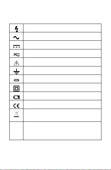
Safety Symbols
High voltage warning
AC (Alternating current)
DC (Direct current)
AC or DC
Warning
Ground
Fuse
double insulation/reinforced insulation protection
Low battery voltage
Product complies with all relevant European laws
The additional product label shows that do not discard this
electrical/electronic product into household garbage.
CAT. II
Class II measurements are suitable for testing and measuring
circuits directly connected to power points (sockets and
similarities) of low voltage power installations.

7
CAT. III
Class III measurement is suitable for testing and measuring
circuits connected to the distribution part of low voltage power
supply devices in buildings.
CAT. IV
Class IV measurements are suitable for testing and measuring
circuits connected to the power supply of low voltage power
installations in buildings.
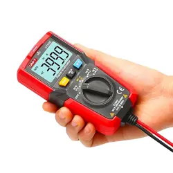
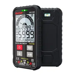
Overview
This meter is an intelligent true effective value
multimeter. Intelligent identification and manual
function are integrated, which can measure AC
and DC voltage, AC and DC current, resistance,
capacitance, continuity, diode, NCV, etc.;It is the
best choice for professional electrician, engineer,
electronic enthusiast or family use.
8
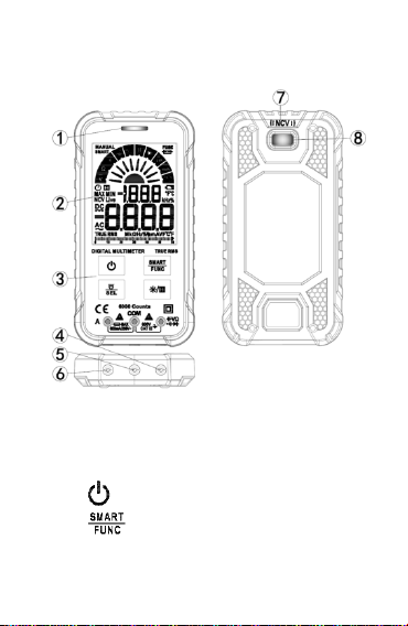
Meter panel
① indicator light
② Display
③ Keys
:Power key
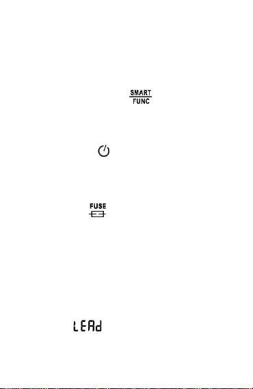
:Function select key。After the meter
is powered on, it defaults to smart function.

9
Press this key once to switch to manual
function, Press this key again to switch to
other functions. Press this key for more
than 2 seconds to restore smart function
:Function selection / flashlight key.
When a position has multiple functions,
press this key to switch; press this key for
more than 2 seconds to turn on or off the
flashlight
:Backlight / data hold key. Press this
key to turn on or off the data holding
function; press this key for more than 2
seconds to turn on or off the backlight
④ Measuring input terminals except current
⑤ COM input terminals
⑥ Current input terminals
⑦ NCV sensor
⑧ Flashlight
10
Auto power off
No operation within 15 minutes, the meter will
auto power off.
Press and hold the " " key and turn on
the power, the auto power off function will be
cancelled.
When the " " symbol is displayed, it
means that the auto power off function is on
Fuse burn out prompt
When the " " symbol is displayed, it
indicates that the fuse is burnt out. Please
replace the fuse
The probe Wrong prompt
When the current measurement function is used,
if the probe is not inserted into the current input
terminal, " " will be displayed.

11
Measurement operation
WARNNING
1) Voltage higher than 600V cannot be
measured; otherwise the meter may be
damaged.
2) Pay special attention to safety when
measuring high voltage to avoid electric
shock or personal injury.
3) Before use, use the meter to test the
known voltage and confirm that the
meter is in good condition.
SMART measurement
It can measure DC voltage, AC voltage,
resistance, continuity. The meter can measure
automatically without user selection function.
This measurement function is default when
power on.

12
1) Press " " key to turn on the power, and the
meter displays " " to enter the smart
measurement function.
2) Insert the red probe into the " " input
terminal and the black probe into the "COM"
input terminal.
3) Connect the probe with voltage source or
resistor in parallel for measurement, and the
meter will automatically recognize the
currently measured signal.
4) When measuring AC voltage, the frequency
will be displayed at the same time.
5) When measuring the resistance, when the
resistance is less than about 50Ω, the buzzer
will sound and the indicator light will be on.
6) Read the results on the display.
Note
:
Minimum measurable voltage: AC0.5V
;
DC0.8V
13
DC/AC mV measurement
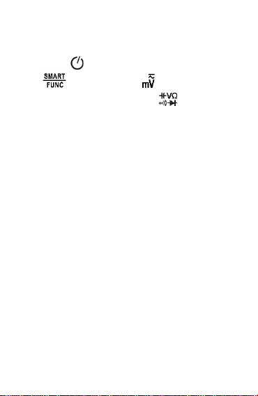
1) Press " " key to turn on the power, press "
" key to Switch to " " function.
2) Insert the red probe into the " " input
terminal and the black probe into the "COM"
input terminal.
3) Connect the probe with voltage source or both
ends of load in parallel for measurement.
4) When measuring AC voltage, the frequency
will be displayed at the same time.
5) Read the results on the display.
Note:
When the probe is not connected with the
measuring circuit, the meter display reading
may not be zero, which is normal and will not
affect the normal measurement.
14
Frequency/Duty measurement
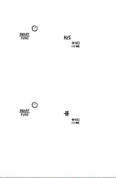
1) Press " " key to turn on the power, press "
" key to Switch to " " function.
2) Insert the red probe into the " " input
terminal and the black probe into the "COM"
input terminal.
3) Connect the probe with voltage source or both
ends of load in parallel for measurement.
4) Read the results on the display.
Capacitance measurement
1) Press " " key to turn on the power, press "
" key to Switch to " " function.
2) Insert the red probe into the " " input
terminal and the black probe into the "COM"
input terminal.
3) Connect the probe with both ends of capacitor
in parallel for measurement.
15
4) Read the results on the display.
WARNNING
When measuring capacitance, please
disconnect the power supply and discharge
capacitors, otherwise the instrument may be
damaged and may suffer electric shock.
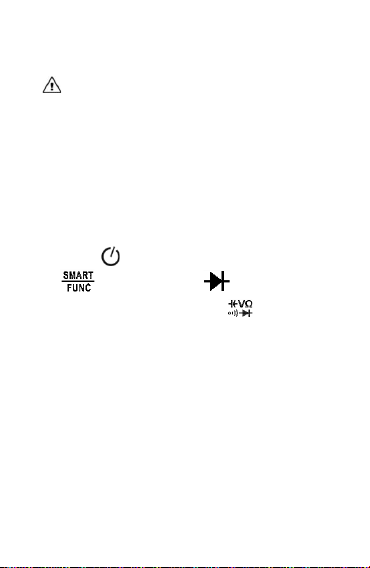
Diode test
1) Press " " key to turn on the power, press "
" key to Switch to " " function.
2) Insert the red probe into the " " input
terminal and the black probe into the "COM"
input terminal.
3) Connect the red probe to diode anode and
connect the black probe to diode cathode.
4) Read the results on the display.
Note 1:The meter shows is approximation of
diode forward voltage drop. The forward
16
voltage drop of the diode is generally in the
range of 0.3V to 0.8V.
Note 2:If the probe has reverse connection or
the probe is open, the meter will show “OL”.
DC/AC current measurement
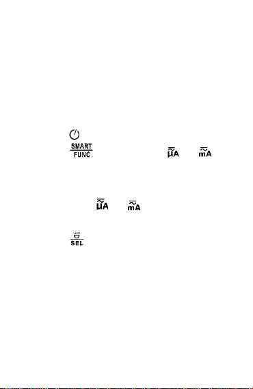
1) Press " " key to turn on the power.
2) Press " " key to Switch to " " or " "
function; or directly insert the red probe into
"A" Current input terminal and automatically
switch to the “ " or " " function.
3) The black probe into the "COM" input terminal.
4) Press " " key to switch to AC or DC current
5) Disconnect the power supply, connect the
meter in series to the circuit under test, and
then turn on the power supply.
6) When measuring AC current, the frequency is
displayed at the same time.
17
7) Read the results on the display
WARNNING
1) Pay special attention to safety when
measuring high voltage to avoid electric
shock or personal injury.
2) Before use, use the meter to test the
known voltage or current and confirm
that the meter is in good condition.
Caution
To avoid damaging meter or equipment, and
ensure that the measured current does not
exceed the rated maximum current of 600mA;
And use the correct input terminal.
NCV Detection
1) Press " " key to turn on the power, press "
" key to Switch to " " function. The
meter shows “NCV”.

18
2) Detection with the meter of NCV sensing area。
3) When the meter senses weak AC signal, the
green indicator light will be on, and the buzzer
will beep slowly, displaying "--- L".
4) When the meter senses strong AC signal, the
red indicator light will be on, and the buzzer
will beep fast, displaying "--- H".
WARNNING
When using the NCV function, please remove
the probe, otherwise the detection accuracy
will be affected.
NCV function is affected by many factors,
even if there is no alarm prompt, there may
still be high voltage
Live test
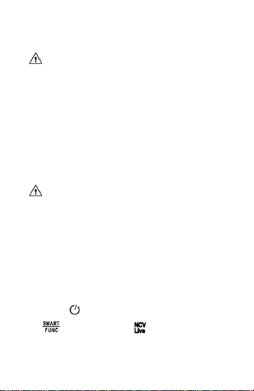
1) Press " " key to turn on the power, press "
" key to Switch to " " function. Then

19
press " " key to switch to live function, the
meter shows “Live”.
2) Insert the red probe into the " " input
terminal and remove the black probe from the
"COM" input terminal.
3) When the meter detected weak AC signal, the
green indicator light will be on, and the buzzer
will beep slowly, displaying "--- L".
4) When the meter detected strong AC signal,
the red indicator light will be on, and the
buzzer will beep fast, displaying "--- H". In
general, what is detected is the live at this time
WARNNING
Please remove the black probe; otherwise the
detection accuracy will be affected.
General technical
Environmental conditions:

20
CAT. III 600V;
Pollution:2
Altitude < 2000m。
Working temperature and humidity:
0~40°C(<80% RH,<10°C non-condensing)
Storage temperature and humidity:
-10~60°C(<70% RH, without batteries)。
Temperature coefficient:
0.1Accuracy /°C(<18°C or >28°C)。
Maximum voltage allowed between input
terminals:600V
Current protection:F600mA/250V fuse
Sampling: approx. 3 times / second.
Display: maximum 6000 count.
Over range indication: display "OL".
Low battery: Display “ ”.
Polarity indication: display "-" sign.
Power:2 x 3V CR2032 batteries.
21
Accuracy
Accuracy is applicable within one year after
calibration
Reference conditions: ambient temperature 18°C
to 28°C, relative humidity no more than 80%
Accuracy: ± (% reading + word)
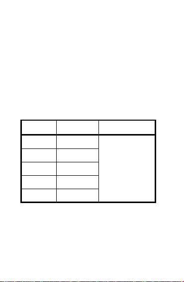
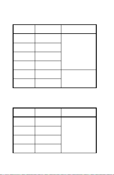
DC voltage
Range
Resolution
Accuracy
60mV
0.01mV
±(0.5% +3)
600mV
0.1mV
6V
0.001V
60V
0.01V
600V
0.1V
Input impedance:10MΩ
Maximum voltage:600V
22
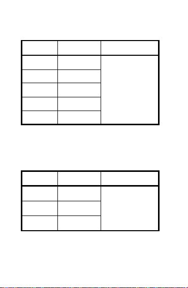
AC voltage
Range
Resolution
Accuracy
60mV
0.01mV
±(1.0%+3)
600mV
0.1mV
6V
0.001V
60V
0.01V
600V
0.1V
Input impedance:10MΩ;Maximum voltage:600V
Frequency Response:40Hz ~ 1kHz;True RMS
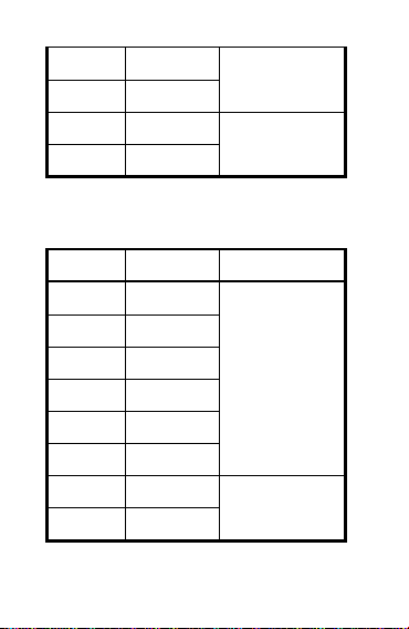
DC current
Range
Resolution
Accuracy
6000A
1A
±(1.2%+5)
60mA
0.01mA
600mA
0.1mA
Overload protection:F600mA/250V Fuse;
Maximum current:600mA
23
AC current
Range
Resolution
Accuracy
6000A
1A
±(1.5%+5)
60mA
0.01mA
600mA
0.1mA
Overload protection:F600mA/250V Fuse;
Maximum current:600mA
Frequency Response:40Hz ~ 1kHz;True RMS
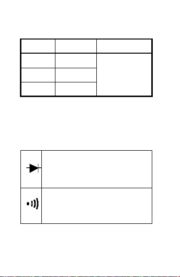
Diode & Continuity
Display diode forward voltage
Open Voltage: Approx. 2.0V
Overload protection:250V
<Approx.50,the buzzer sound
Open Voltage: Approx. 1.0V
Overload protection:250V
24
Resistance
Range
Resolution
Accuracy
600Ω
0.1Ω
±(1.0%+5)
6kΩ
0.001kΩ
60kΩ
0.01kΩ
600kΩ
0.1kΩ
6MΩ
0.001MΩ
±(1.5%+3)
60MΩ
0.01MΩ
Overload protection:250V
Capacitance
Range
Resolution
Accuracy
6nF
0.001nF
±(4.0%+5)
60nF
0.01nF
600nF
0.1nF
6F
0.001F
25
60F
0.01F
600F
0.1F
6mF
0.001mF
±(5.0%+5)
60mF
0.01mF
Overload protection:250V
Frequency/Duty
Range
Resolution
Accuracy
10Hz
0.001Hz
±(1.0%+5)
100Hz
0.01Hz
1000Hz
0.1Hz
10kHz
0.001kHz
100kHz
0.01kHz
1000kHz
0.1kHz
10MHz
0.001MHz
±(3.0%+5)
1~99%
0.1%
Hz/% Position:

26
1) Range:10Hz ~ 10MHz
2) Voltage response:0.5~10V AC
3) Overload protection:250V
ACV Position:
1) Range:10Hz ~ 2 kHz
2) Voltage response:≥ 0.5V AC
3) Overload protection:250V
A or mA Position:
1) Range:10Hz ~ 2 kHz
2) Current response:≥ 2mA
3) Overload protection:F600mA/250V fuse;
Maintain
Clean
If there is dust or humidity on the input terminal,
wrong measurement may occur. Clean the
instrument as follows:

27
1) Turn off the meter power and remove the test
probe。
2) Wipe the case with a damp cloth or mild
detergent. Do not use abrasives or solvents.
Wipe the contacts in each input jack with a
clean cotton swab soaked in alcohol.
WARNNING
Please keep the inside of the meter clean and
dry at all times to prevent electric shock or
damage to the instrument
Replace battery or fuse
Replace battery
1) Turn off the meter power and remove the test
probe。
2) Using a screwdriver, remove the screws that
secure the battery cover and remove the
battery cover.

28
3) Remove the old battery and replace it with a
new battery of the same specification. Please
pay attention to the polarity of the battery.
4) Replace the battery cover in its original
position, and fix and lock the battery cover
with screws.
WARNNING
In order to avoid electric shock or personal
injury caused by wrong reading, please
replace the battery immediately when the
battery power is low.
Do not discharge the battery by shorting it or
reversing its polarity.
In order to ensure the safe operation and
maintenance of the meter, please take out the
battery when it is not used for a long time, so
as to prevent the battery leakage from

29
damaging the meter.
Replace fuse
1) Turn off the meter power and remove the test
probe。
2) Use a screwdriver to unscrew the screws that
fix the back cover and remove the back cover.
3) Remove the burned fuse tube, replace it with a
new one of the same specification, and make
sure that the fuse tube is installed in the fuse
clip and clamped tightly.
4) Install the back cover and lock it with
screws.
WARNNING
To prevent possible electric shock, personal
injury or damage to the meter, use fuses of
the same specification or specified
specification.