GLXD4R+
Wireless Receiver
Online user guide for GLXD4R+ wireless system. Includes setup instructions, specifications, and more.
Version: 0.1 (2022-K)

Shure Incorporated
2/39
Table of Contents
GLXD4R+ Wireless Receiver 3
System Overview 3
Features 3
Receiver 3
Receiver Screen 5
Set Up the Receiver 6
Transmitters 7
Transmitter Status LED 8
Wearing the Bodypack 8
Wearing the Headworn Microphone 9
Correct Microphone Placement 9
Install Transmitter Batteries 9
Batteries and Charging 10
Receiver Charging Bay 10
Charging from an AC Power Source 11
Charging Status LEDs 11
Charging Times and Transmitter Runtimes 11
Important Tips for Care and Storage of Shure Recharge
able Batteries 12
Tips to Improve Wireless System Performance 12
Additional Tips 13
Rack-Mounting Instructions 13
Remote Antenna Placement 14
System Set Up 15
Manually Linking Receivers and Transmitters 15
Linking Two Transmitters to a Receiver 15
Identifying Linked Transmitters and Receivers with Re
mote ID 15
Multiple Receiver Systems 16
Receiver Band Modes 16
Gain Adjustment 17
Locking and Unlocking the Controls 17
Locking the Receiver Controls 17
Locking the Transmitter Controls 17
Receiver Display Brightness 17
Firmware 18
Resetting Components 18
Resetting the Receiver 18
Resetting the Transmitter 18
Troubleshooting 18
Accessories 20
Specifications 21
Diagrams 26
Frequency Tables 26
IMPORTANT SAFETY INSTRUCTIONS 33
WARNING 35
Note: 35
Information to the user 35
Certifications 36
Shure Incorporated
3/39
•
•
•
•
•
•
•
•
•
•
GLXD4R+
Wireless Receiver
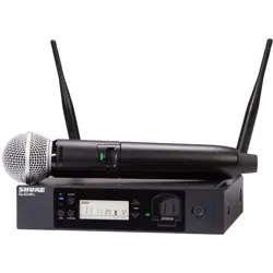
System Overview
GLX-D+ wireless systems combine automatic frequency management technology with a rack mountable metal receiver,
rechargeable lithiumion batteries, worldrenowned microphones, and unparalleled design and construction. GLXD+ Frequen
cy Managers (available separately) connect multiple GLXD4R+ receiver systems for increased channel count and improved RF
reliability, consolidating RF to one pair of antennas. New antenna accessories help improve reception by letting you mount an
tennas closer to transmitters, with directional reception for improved performance. Available in a variety of bodypack and hand
held configurations, GLX-D+ sets the standard for ease of operation and digital audio clarity.
Features
Exceptional digital audio clarity
Operates in 2.4 GHz and 5.8 GHz spectrum
Optional GLX-D+ Frequency Manager allows operation of up to 16 systems
Antenna accessories for remote mounting and improved reception
Half-rack size and metal chassis
Rechargeable batteries deliver cost efficiency
Adjustable transmitter gain to optimize audio signal
Automatically moves away from interference without audio interruption
RF back-channel for remote control of transmitter functions
Automatic transmitter power-off to conserve battery life when transmitter is not in use
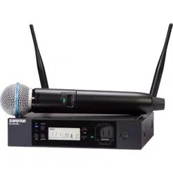
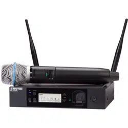
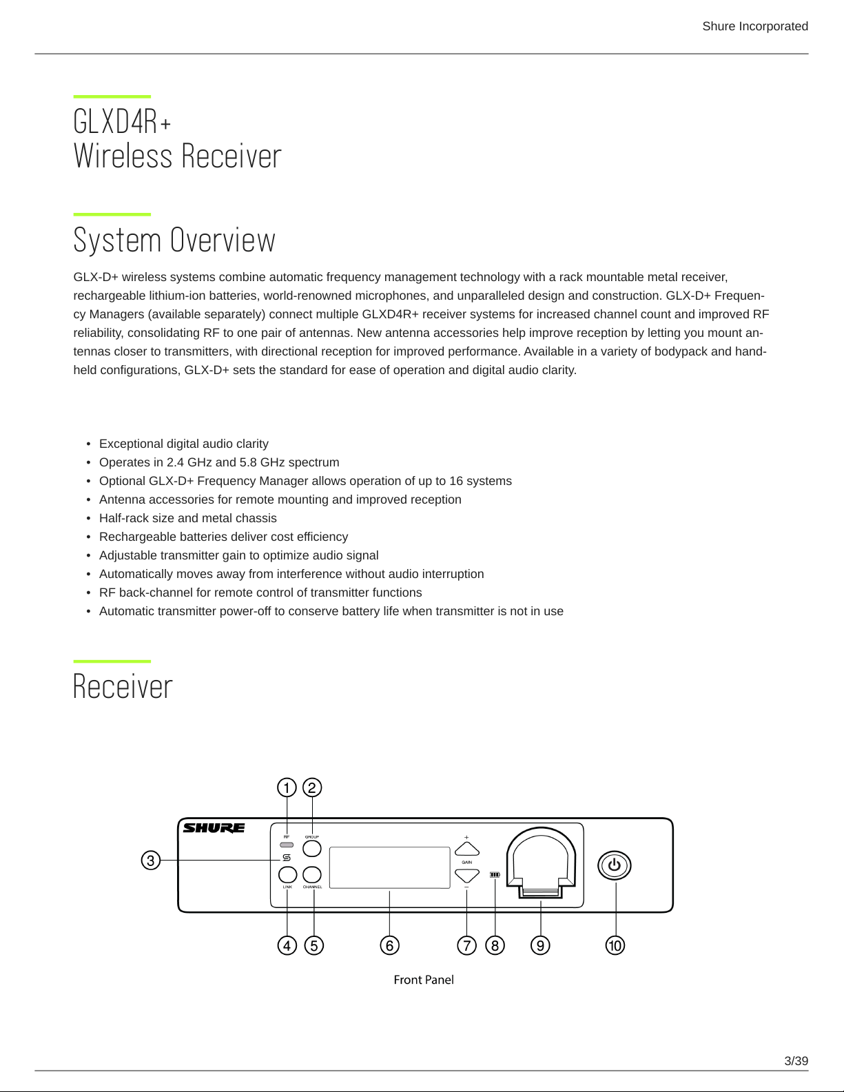
Receiver
Shure Incorporated
4/39
◦
◦
◦
◦
◦
◦
① RF status LED
ON = Linked transmitter is on
Flashing = Searching for transmitter
OFF = Linked transmitter off or transmitter unlinked
② Group button
Press and hold for two seconds to enable manual group edit.
③ Data sync LED
ON = Data sync is on (receiver connected to GLX-D+ frequency manager)
Flashing = Searching for frequencies
OFF = Data sync is off (receiver not connected to GLX-D+ frequency manager)
④ Link button
Press to manually link receiver to a transmitter or to activate the remote ID function.
⑤ Channel button
Press to start a channel scan.
⑥ Display
Shows receiver and transmitter status.
⑦ Gain buttons
Press to increase or decrease transmitter gain in 1 dB increments.
⑧ Battery charging indicator
Shure Incorporated
5/39
◦
◦
◦
◦
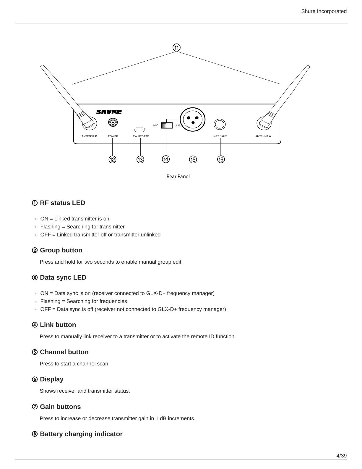
Illuminates when battery is in charging bay:
Red = Battery charging
Green Flashing = Battery charge at 90%
Green = Battery charged
Amber Flashing = Charging error, replace battery
⑨ Battery charging bay
Charges transmitter battery.
⑩ Power button
Powers the unit on and off.
⑪ Antenna
Two antennas per receiver. Antennas pick up the signal from the transmitter.
⑫ Power supply port
Connect the supplied 15 V DC external power supply.
⑬ USB-C port
Connect to computer to download firmware updates.
⑭ Mic/Line switch
Sets XLR output level to microphone or line level.
⑮ XLR audio output
Supplies microphone-level or line-level audio output.
⑯ Inst/Aux output
TRS ¼" (6.35mm) audio output. Connect to mixers, recorders, and amplifiers.
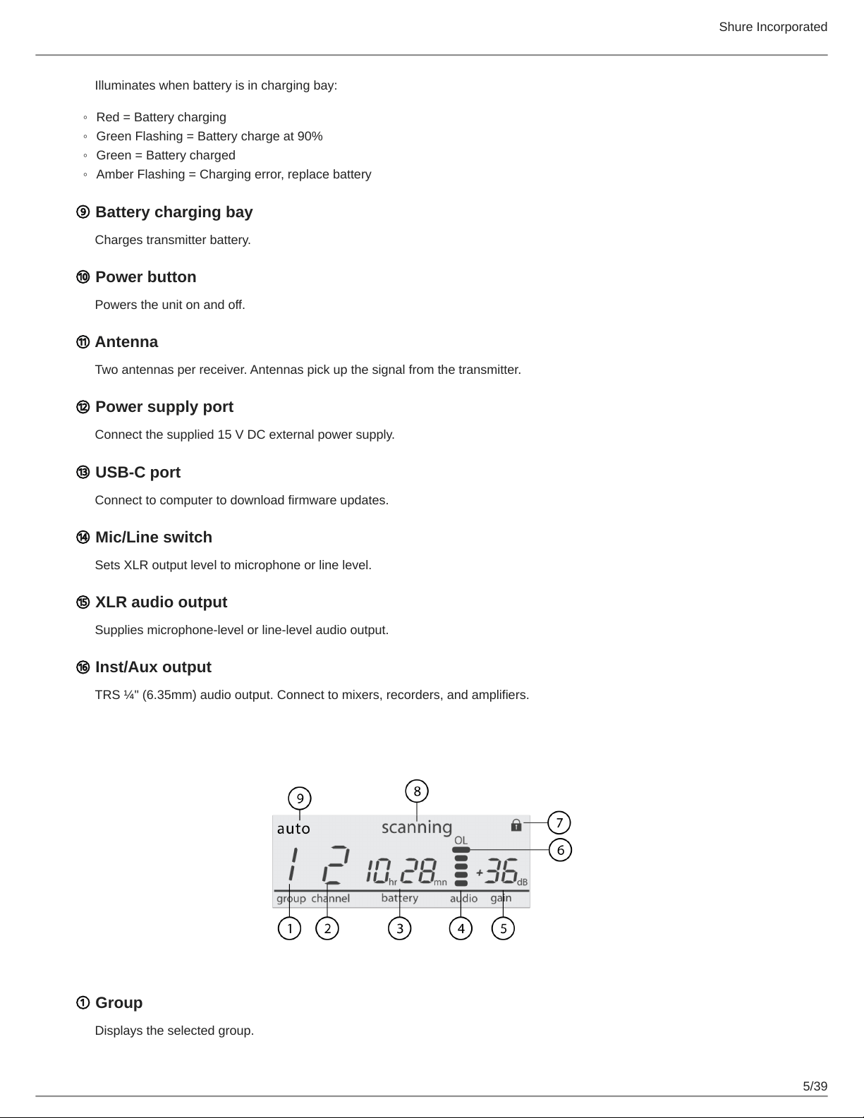
Receiver Screen
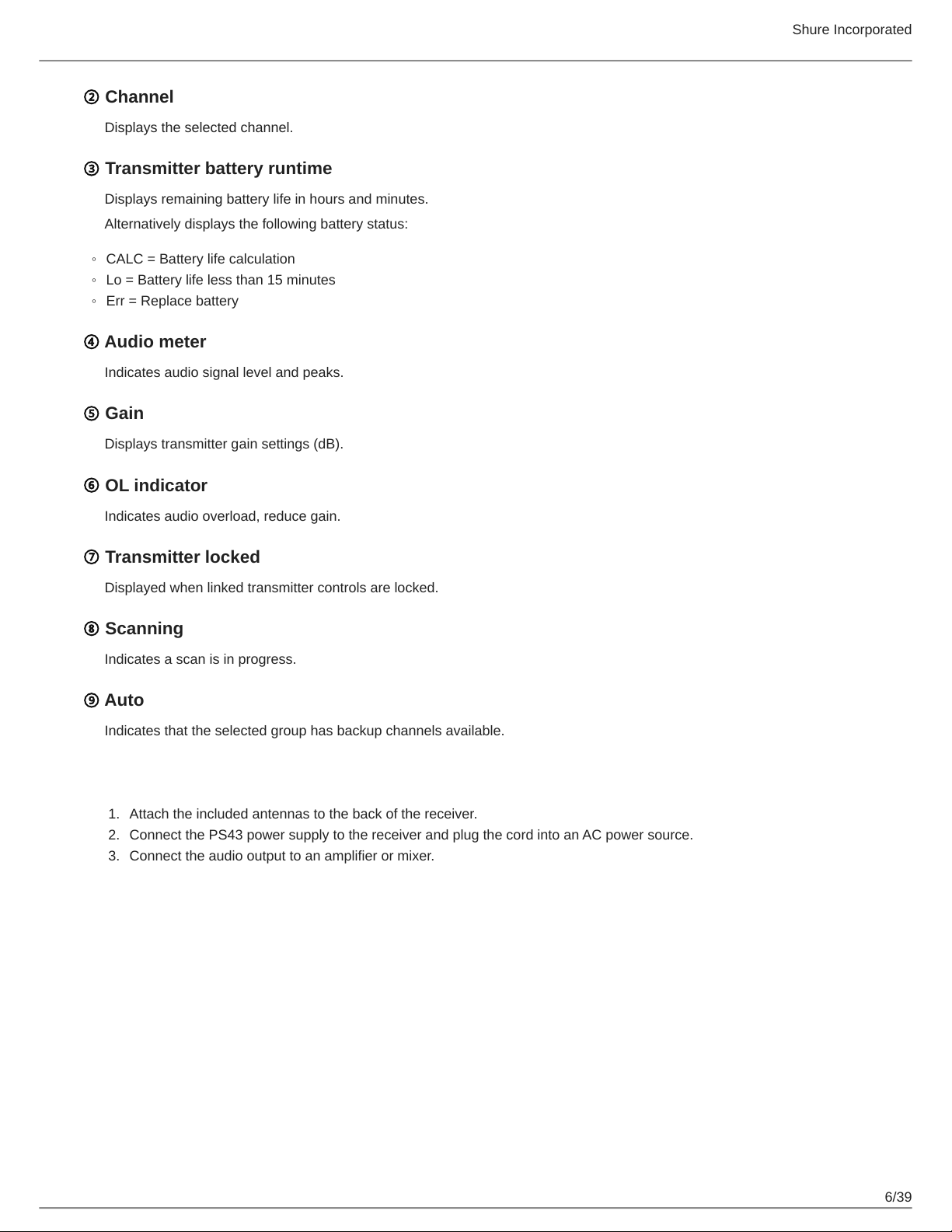
① Group
Displays the selected group.
Shure Incorporated
6/39
◦
◦
◦
1.
2.
3.
② Channel
Displays the selected channel.
③ Transmitter battery runtime
Displays remaining battery life in hours and minutes.
Alternatively displays the following battery status:
CALC = Battery life calculation
Lo = Battery life less than 15 minutes
Err = Replace battery
④ Audio meter
Indicates audio signal level and peaks.
⑤ Gain
Displays transmitter gain settings (dB).
⑥ OL indicator
Indicates audio overload, reduce gain.
⑦ Transmitter locked
Displayed when linked transmitter controls are locked.
⑧ Scanning
Indicates a scan is in progress.
⑨ Auto
Indicates that the selected group has backup channels available.
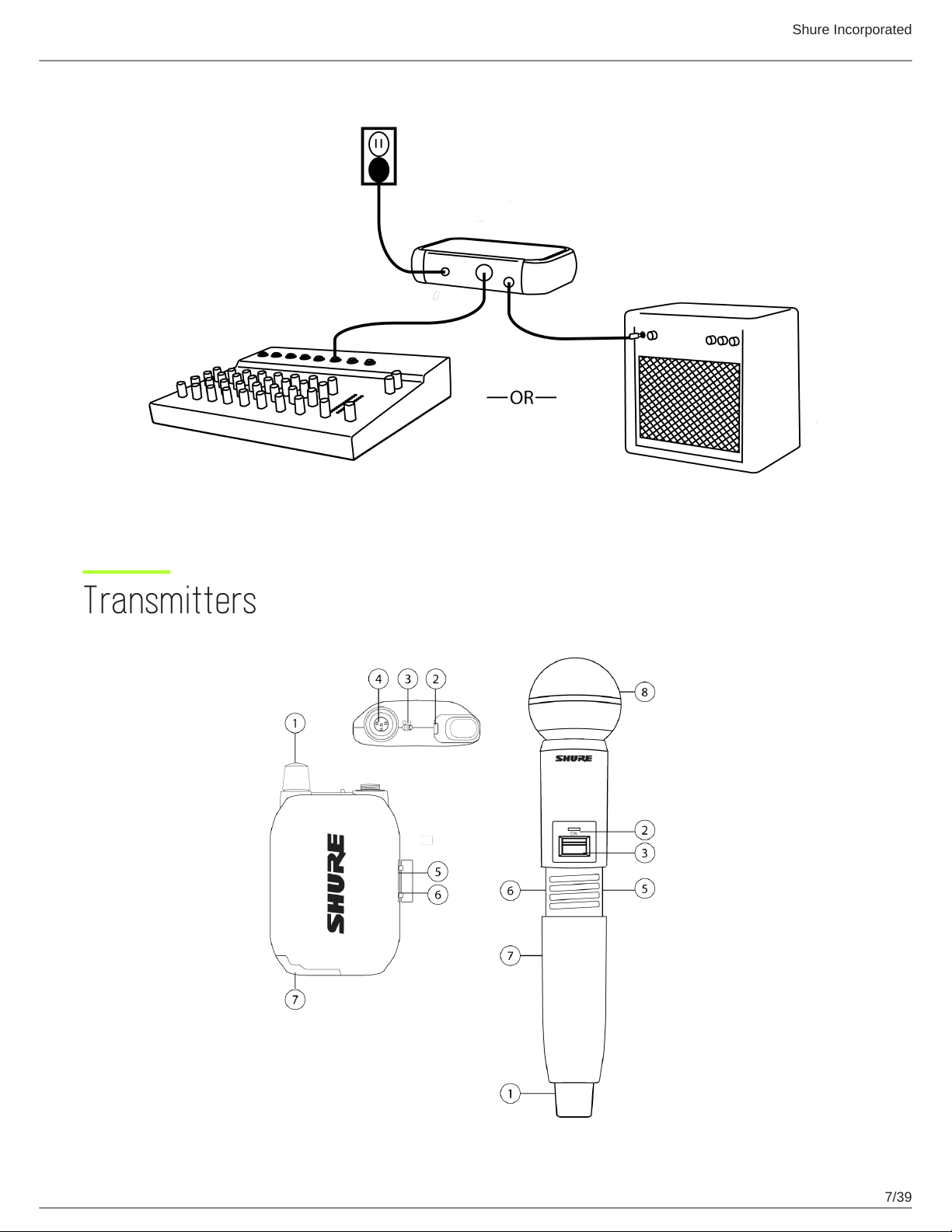
Set Up the Receiver
Attach the included antennas to the back of the receiver.
Connect the PS43 power supply to the receiver and plug the cord into an AC power source.
Connect the audio output to an amplifier or mixer.
Shure Incorporated
7/39
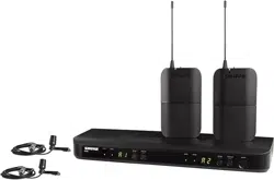
Transmitters
Shure Incorporated
8/39
◦
◦
① Antenna
Carries wireless signal.
② Status LED
LED color and state indicate transmitter status.
③ Power switch
Turns the transmitter on/off.
④ TA4M input port
Connects to a 4-Pin mini connector (TA4F) microphone or instrument cable.
⑤ USB-C charging port
Connect to USB battery charger.
⑥ Link button
Press and hold within 5 seconds of power-on to manually link with receiver.
Press momentarily to activate remote ID function.
⑦ Battery compartment
Holds 1 Shure rechargeable battery.
⑧ Microphone cartridge
GLXD2+ transmitter models are available with the following cartridge types: SM58, Beta 58, Beta 87A.
Transmitter Status LED
LED is green during normal operation.
LED color or flashing indicates a change in transmitter status as shown in the following table:
Color State Description
Green
Flashing (slow) Transmitter attempting relink with receiver
Flashing (fast) Unlinked transmitter searching for receiver
Flashes 3 times Indicates locked transmitter when power switch is pressed
Red
On Battery life < 1 hour
Flashing Battery life < 30 minutes
Red/Green Flashing Remote ID active
Amber Flashing Battery error; remove and insert again, or replace battery
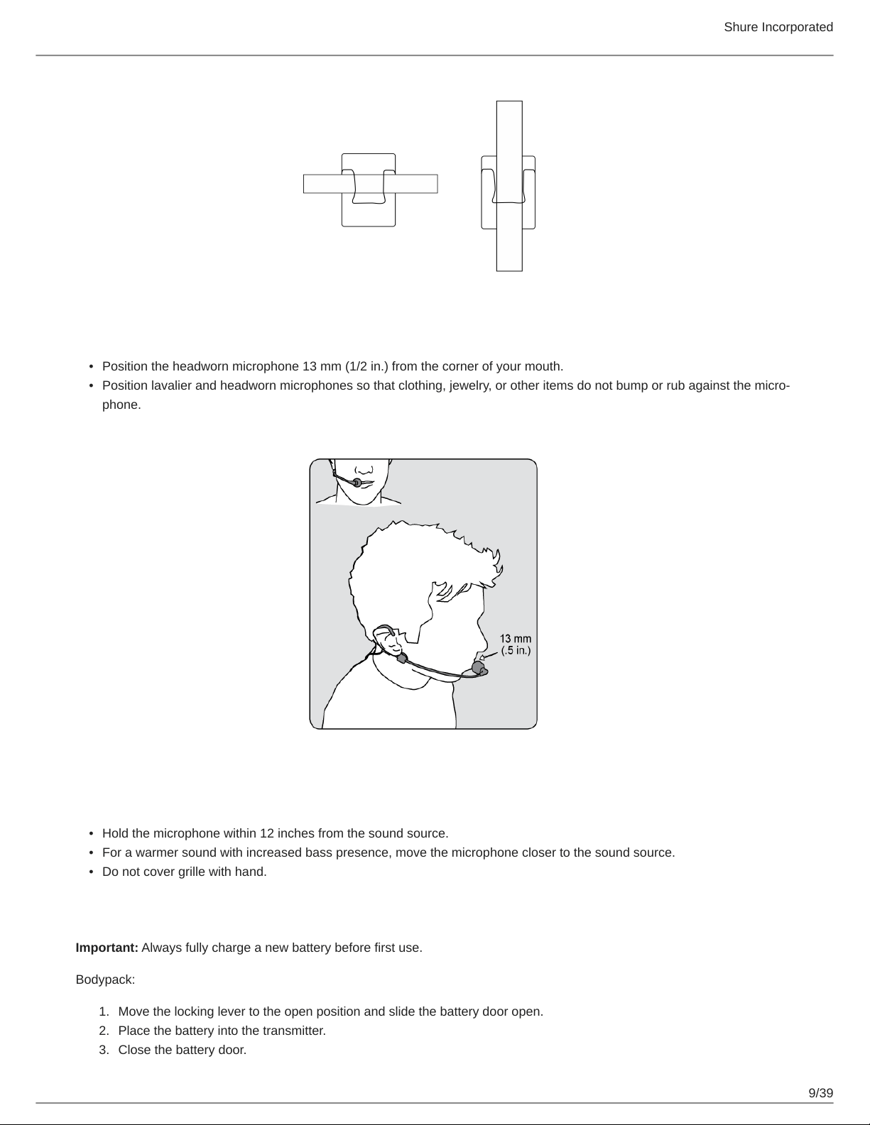
Wearing the Bodypack
Clip the bodypack to a belt or slide a guitar strap through the bodypack clip as shown.
For best results, the belt should be pressed against the base of the clip.
Shure Incorporated
9/39
•
•
•
•
•
1.
2.
3.
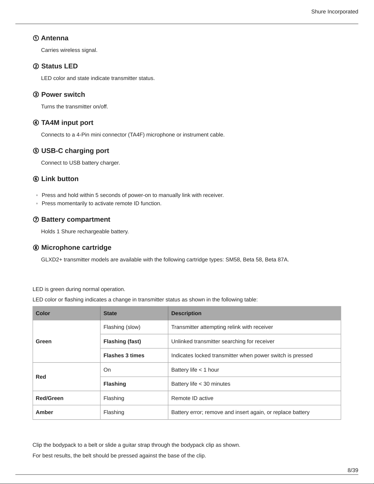
Wearing the Headworn Microphone
Position the headworn microphone 13 mm (1/2 in.) from the corner of your mouth.
Position lavalier and headworn microphones so that clothing, jewelry, or other items do not bump or rub against the micro
phone.
Correct Microphone Placement
Hold the microphone within 12 inches from the sound source.
For a warmer sound with increased bass presence, move the microphone closer to the sound source.
Do not cover grille with hand.
Install Transmitter Batteries
Important: Always fully charge a new battery before first use.
Bodypack:
Move the locking lever to the open position and slide the battery door open.
Place the battery into the transmitter.
Close the battery door.
Shure Incorporated
10/39
1.
2.
3.
1.
2.
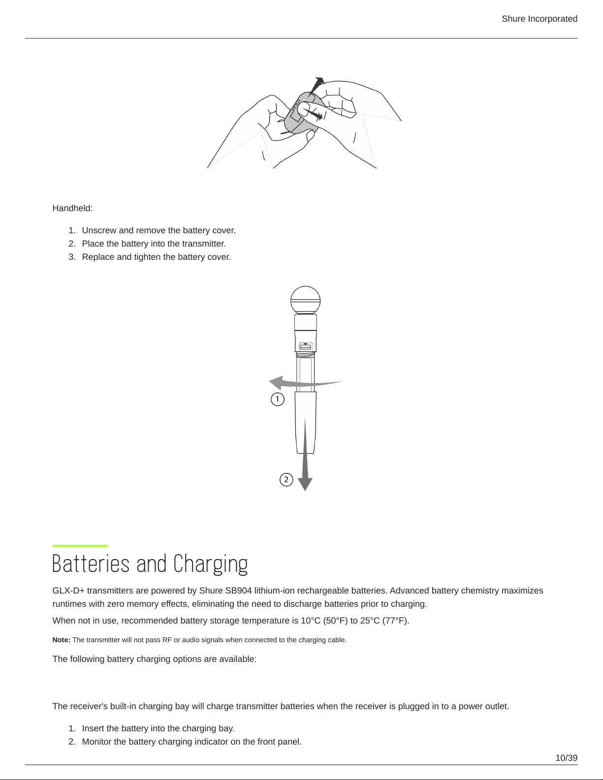
Handheld:
Unscrew and remove the battery cover.
Place the battery into the transmitter.
Replace and tighten the battery cover.
Batteries and Charging
GLX-D+ transmitters are powered by Shure SB904 lithium-ion rechargeable batteries. Advanced battery chemistry maximizes
runtimes with zero memory effects, eliminating the need to discharge batteries prior to charging.
When not in use, recommended battery storage temperature is 10°C (50°F) to 25°C (77°F).
Note: The transmitter will not pass RF or audio signals when connected to the charging cable.
The following battery charging options are available:
Receiver Charging Bay
The receiver's built-in charging bay will charge transmitter batteries when the receiver is plugged in to a power outlet.
Insert the battery into the charging bay.
Monitor the battery charging indicator on the front panel.
Shure Incorporated
11/39
1.
2.
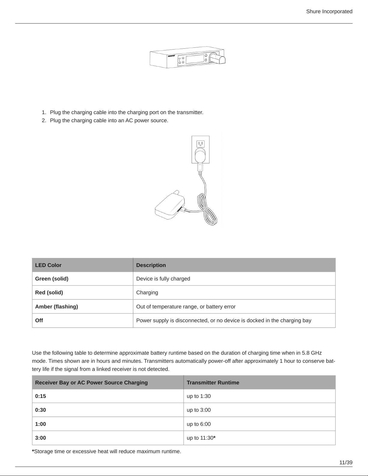
Charging from an AC Power Source
Plug the charging cable into the charging port on the transmitter.
Plug the charging cable into an AC power source.
Charging Status LEDs
LED Color Description
Green (solid) Device is fully charged
Red (solid) Charging
Amber (flashing) Out of temperature range, or battery error
Off Power supply is disconnected, or no device is docked in the charging bay
Charging Times and Transmitter Runtimes
Use the following table to determine approximate battery runtime based on the duration of charging time when in 5.8 GHz
mode. Times shown are in hours and minutes. Transmitters automatically poweroff after approximately 1 hour to conserve bat
tery life if the signal from a linked receiver is not detected.
Receiver Bay or AC Power Source Charging Transmitter Runtime
0:15 up to 1:30
0:30 up to 3:00
1:00 up to 6:00
3:00 up to 11:30*
*Storage time or excessive heat will reduce maximum runtime.
Shure Incorporated
12/39
•
•
•
1.
◦
◦
2.
◦
◦
◦
Note: If receiver is powered off and remains plugged in, battery will continue charging.
Important Tips for Care and Storage of Shure Rechargeable Batteries
Proper care and storage of Shure batteries results in reliable performance and ensures a long lifetime.
Always store batteries and transmitters at room temperature
Ideally, batteries should be charged to approximately 40% of capacity for long-term storage
During storage, check batteries every 6 months and recharge to 40% of capacity as needed
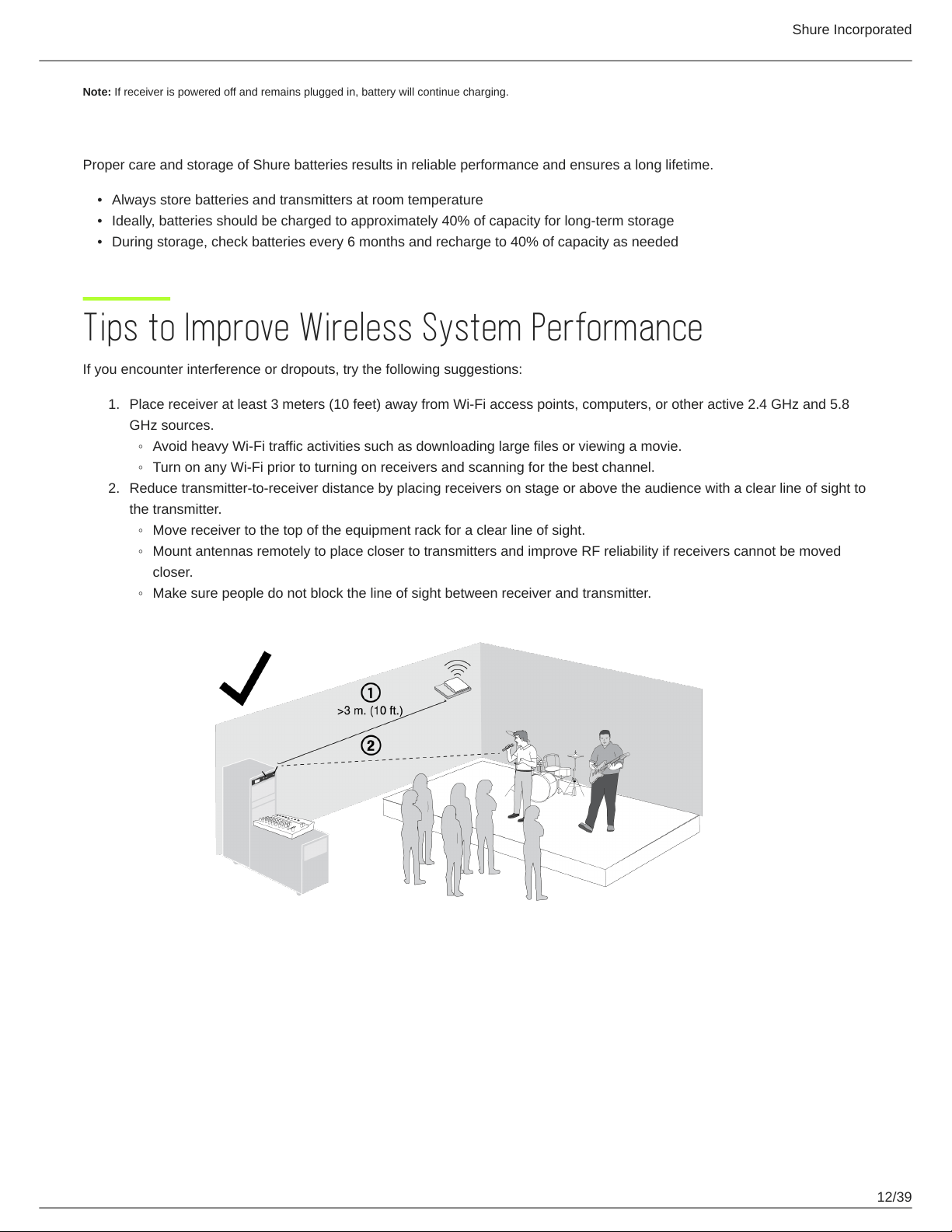
Tips to Improve Wireless System Performance
If you encounter interference or dropouts, try the following suggestions:
Place receiver at least 3 meters (10 feet) away from Wi-Fi access points, computers, or other active 2.4 GHz and 5.8
GHz sources.
Avoid heavy Wi-Fi traffic activities such as downloading large files or viewing a movie.
Turn on any Wi-Fi prior to turning on receivers and scanning for the best channel.
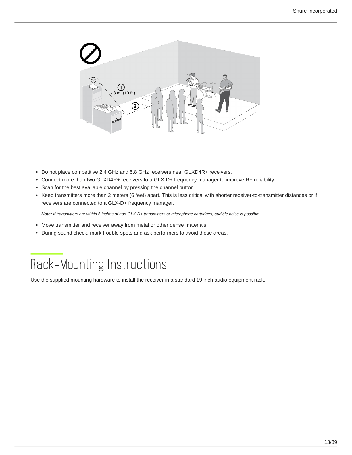
Reduce transmitter-to-receiver distance by placing receivers on stage or above the audience with a clear line of sight to
the transmitter.
Move receiver to the top of the equipment rack for a clear line of sight.
Mount antennas remotely to place closer to transmitters and improve RF reliability if receivers cannot be moved
closer.
Make sure people do not block the line of sight between receiver and transmitter.
Shure Incorporated
13/39
•
•
•
•
•
•
Additional Tips
Do not place competitive 2.4 GHz and 5.8 GHz receivers near GLXD4R+ receivers.
Connect more than two GLXD4R+ receivers to a GLX-D+ frequency manager to improve RF reliability.
Scan for the best available channel by pressing the channel button.
Keep transmitters more than 2 meters (6 feet) apart. This is less critical with shorter receiver-to-transmitter distances or if
receivers are connected to a GLX-D+ frequency manager.
Note: If transmitters are within 6 inches of non-GLX-D+ transmitters or microphone cartridges, audible noise is possible.
Move transmitter and receiver away from metal or other dense materials.
During sound check, mark trouble spots and ask performers to avoid those areas.
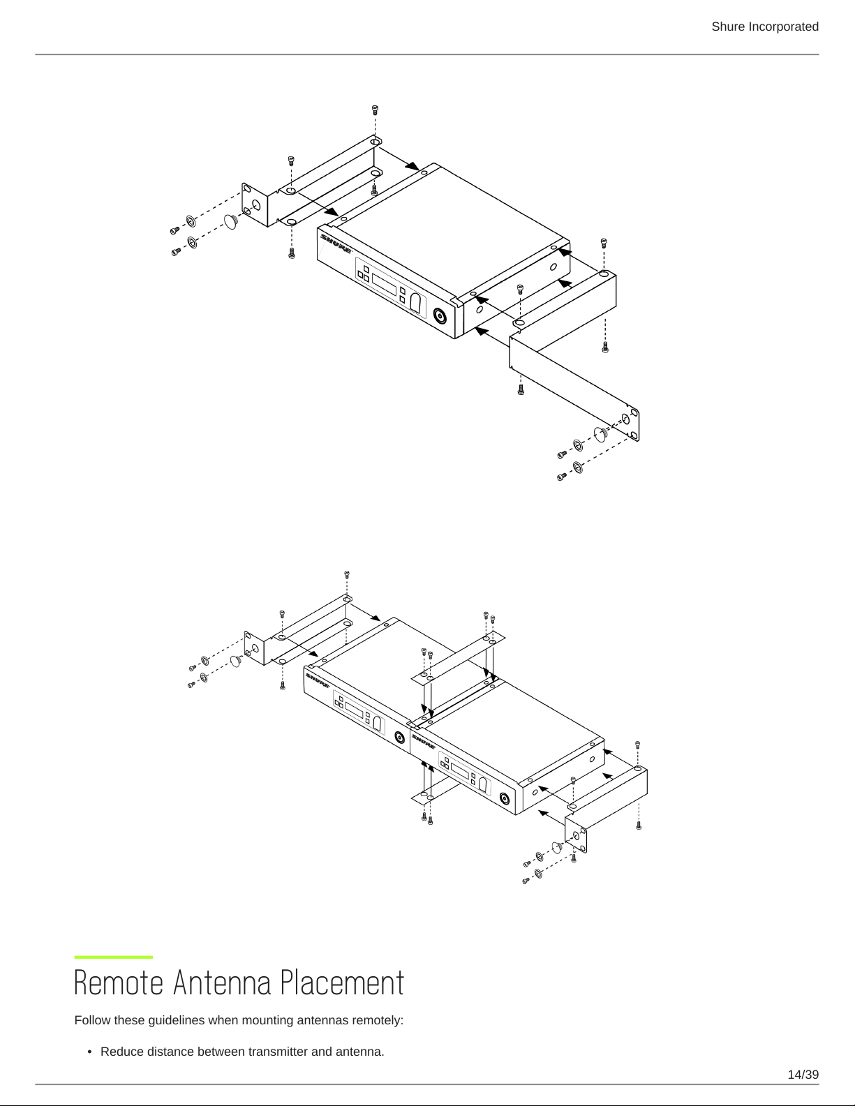
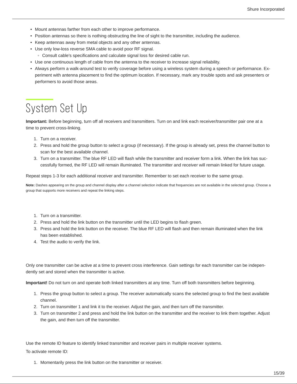
Rack-Mounting Instructions
Use the supplied mounting hardware to install the receiver in a standard 19 inch audio equipment rack.
Shure Incorporated
14/39
•
Remote Antenna Placement
Follow these guidelines when mounting antennas remotely:
Reduce distance between transmitter and antenna.
Shure Incorporated
15/39
•
•
•
•
◦
•
•
1.
2.
3.
1.
2.
3.
4.
1.
2.
3.
1.
Mount antennas farther from each other to improve performance.
Position antennas so there is nothing obstructing the line of sight to the transmitter, including the audience.
Keep antennas away from metal objects and any other antennas.
Use only low-loss reverse SMA cable to avoid poor RF signal.
Consult cable's specifications and calculate signal loss for desired cable run.
Use one continuous length of cable from the antenna to the receiver to increase signal reliability.
Always perform a walkaround test to verify coverage before using a wireless system during a speech or performance. Ex
periment with antenna placement to find the optimum location. If necessary, mark any trouble spots and ask presenters or
performers to avoid those areas.
System Set Up
Important: Before beginning, turn off all receivers and transmitters. Turn on and link each receiver/transmitter pair one at a
time to prevent cross-linking.
Turn on a receiver.
Press and hold the group button to select a group (if necessary). If the group is already set, press the channel button to
scan for the best available channel.
Turn on a transmitter. The blue RF LED will flash while the transmitter and receiver form a link. When the link has suc
cessfully formed, the RF LED will remain illuminated. The transmitter and receiver will remain linked for future usage.
Repeat steps 1-3 for each additional receiver and transmitter. Remember to set each receiver to the same group.
Note: Dashes appearing on the group and channel display after a channel selection indicate that frequencies are not available in the selected group. Choose a
group that supports more receivers and repeat the linking steps.
Manually Linking Receivers and Transmitters
Turn on a transmitter.
Press and hold the link button on the transmitter until the LED begins to flash green.
Press and hold the link button on the receiver. The blue RF LED will flash and then remain illuminated when the link
has been established.
Test the audio to verify the link.
Linking Two Transmitters to a Receiver
Only one transmitter can be active at a time to prevent cross interference. Gain settings for each transmitter can be indepen
dently set and stored when the transmitter is active.
Important! Do not turn on and operate both linked transmitters at any time. Turn off both transmitters before beginning.
Press the group button to select a group. The receiver automatically scans the selected group to find the best available
channel.
Turn on transmitter 1 and link it to the receiver. Adjust the gain, and then turn off the transmitter.
Turn on transmitter 2 and press and hold the link button on the transmitter and the receiver to link them together. Adjust
the gain, and then turn off the transmitter.
Identifying Linked Transmitters and Receivers with Remote ID
Use the remote ID feature to identify linked transmitter and receiver pairs in multiple receiver systems.
To activate remote ID:
Momentarily press the link button on the transmitter or receiver.
Shure Incorporated
16/39
2.
3.
•
•
The screen of the linked receiver will blink and display ID, while the status LED on the linked transmitter will flash red/
green.
To exit remote ID mode, momentarily press the link button or allow the function to timeout.
Multiple Receiver Systems
To run more than two receivers at the same time, the GLX-D+ frequency manager is recommended to improve RF reliability
(only compatible with GLXD4R+).
However, you can run multiple receivers without the frequency manager. Select the group by determining the total number of
receivers in your system. All receivers in the system must be set to the same group.
2.4 GHz and 5.8 GHz bands:
Group Number of Receivers Description
1 2 - 5 typical Default setting
2 2 - 5 typical Best multi-channel group if you experience interference
3 1 Best single-channel group if you experience interference
A*
Up to 11 typical, 16 maxi
mum
Default setting
B* Best multi-channel group if you experience interference
2.4 GHz bands only:
Group Number of Receivers Description
1 2 - 4 typical Default setting
2 2 - 4 typical Best multi-channel group if you experience interference
3 2 - 4 typical, 8 maximum
Only use Group 3 in controlled WiFi environments because there are no back
up frequencies to avoid interference
4 1 Best single-channel group if you experience interference
A*
Up to 9 typical, 11 maxi
mum
Default setting
B* Best multi-channel group if you experience interference
*Groups A and B are only for systems with a GLXD4R+ and GLXD+ frequency manager.
See Tips to Improve Wireless System Performance for additional information. See the GLXD+FM user guide for information
about receiver groups when connected to the GLX-D+ frequency manager.
Receiver Band Modes
There are 3 band modes available for GLXD+ receivers. The band mode options are:
2.4 GHz-only mode
5.8 GHz-only mode
Shure Incorporated
17/39
•
1.
2.
•
•
•
Best band mode – 2.4 and 5.8 GHz (default)
To change the band mode:
Press and hold the channel button while powering on the receiver. Continue to hold the channel button for approximate
ly 5 seconds until the band selection menu opens.
Press the up/down gain button to select a band mode. The screen will flash momentarily and scan for the best channel
to use.
Note: Linked receivers and transmitters must be able to operate in the same band. Transmitters that don’t support the selected band mode will unlink from the
receiver.
Gain Adjustment
Momentarily press the gain buttons on the receiver to adjust the gain of a linked transmitter in 1 dB increments. For faster gain
adjustments, press and hold the gain buttons.
Tip: Monitor the audio and observe the receiver audio meter level while adjusting the gain to prevent signal overload.
Locking and Unlocking the Controls
The controls of the receiver and transmitter can be locked to prevent unauthorized setting changes or poweroff. The lock sta
tus is not changed by power cycles.
Locking the Receiver Controls
Simultaneously press and hold the group and channel buttons until LK appears on the screen. Repeat to unlock.
LK is displayed if a locked control is pressed
UN is displayed momentarily to confirm the unlock command
Locking the Transmitter Controls
To lock directly from the transmitter:
Start with the transmitter off, then press and hold the link button while turning on the transmitter. Release the link button when
the transmitter powers on to prevent an accidental factory reset. The lock icon appears on the receiver screen when locked.
Repeat sequence to unlock.
To lock from the receiver front panel:
Simultaneously press and hold the group and link buttons for approximately 2 seconds until the flashing lock icon appears on
the receiver screen. Repeat sequence to unlock.
Note: The transmitter status LED will flash if a locked switch is set to the off position.
Receiver Display Brightness
To adjust the receiver display brightness, press and hold the group button and any gain button simultaneously. Use the gain
buttons to set the brightness of the display to low, medium, or high.
Low = Br 1
Shure Incorporated
18/39
•
•
•
•
•
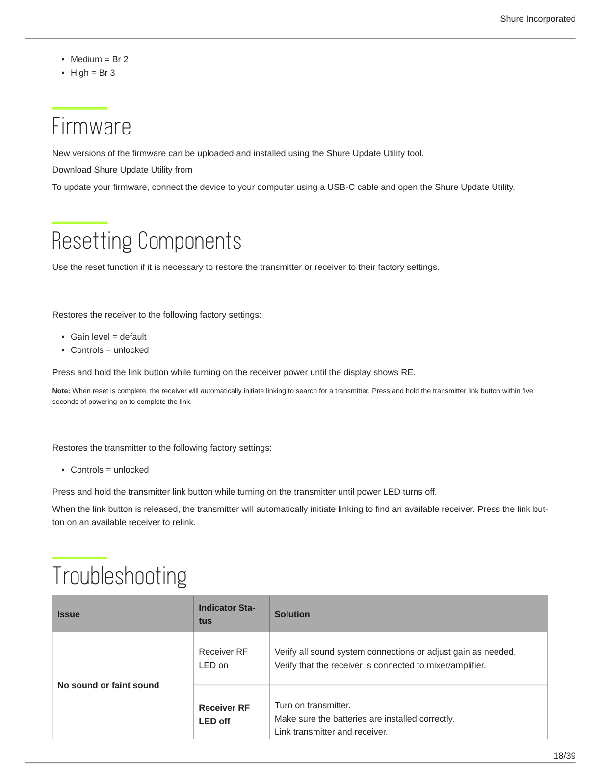
Medium = Br 2
High = Br 3
Firmware
New versions of the firmware can be uploaded and installed using the Shure Update Utility tool.
Download Shure Update Utility from shure.com
To update your firmware, connect the device to your computer using a USB-C cable and open the Shure Update Utility.
Resetting Components
Use the reset function if it is necessary to restore the transmitter or receiver to their factory settings.
Resetting the Receiver
Restores the receiver to the following factory settings:
Gain level = default
Controls = unlocked
Press and hold the link button while turning on the receiver power until the display shows RE.
Note: When reset is complete, the receiver will automatically initiate linking to search for a transmitter. Press and hold the transmitter link button within five
seconds of powering-on to complete the link.
Resetting the Transmitter
Restores the transmitter to the following factory settings:
Controls = unlocked
Press and hold the transmitter link button while turning on the transmitter until power LED turns off.
When the link button is released, the transmitter will automatically initiate linking to find an available receiver. Press the link but
ton on an available receiver to relink.
Troubleshooting
Issue
Indicator Sta
tus
Solution
No sound or faint sound
Receiver RF
LED on
Verify all sound system connections or adjust gain as needed.
Verify that the receiver is connected to mixer/amplifier.
Receiver RF
LED off
Turn on transmitter.
Make sure the batteries are installed correctly.
Link transmitter and receiver.
Shure Incorporated
19/39
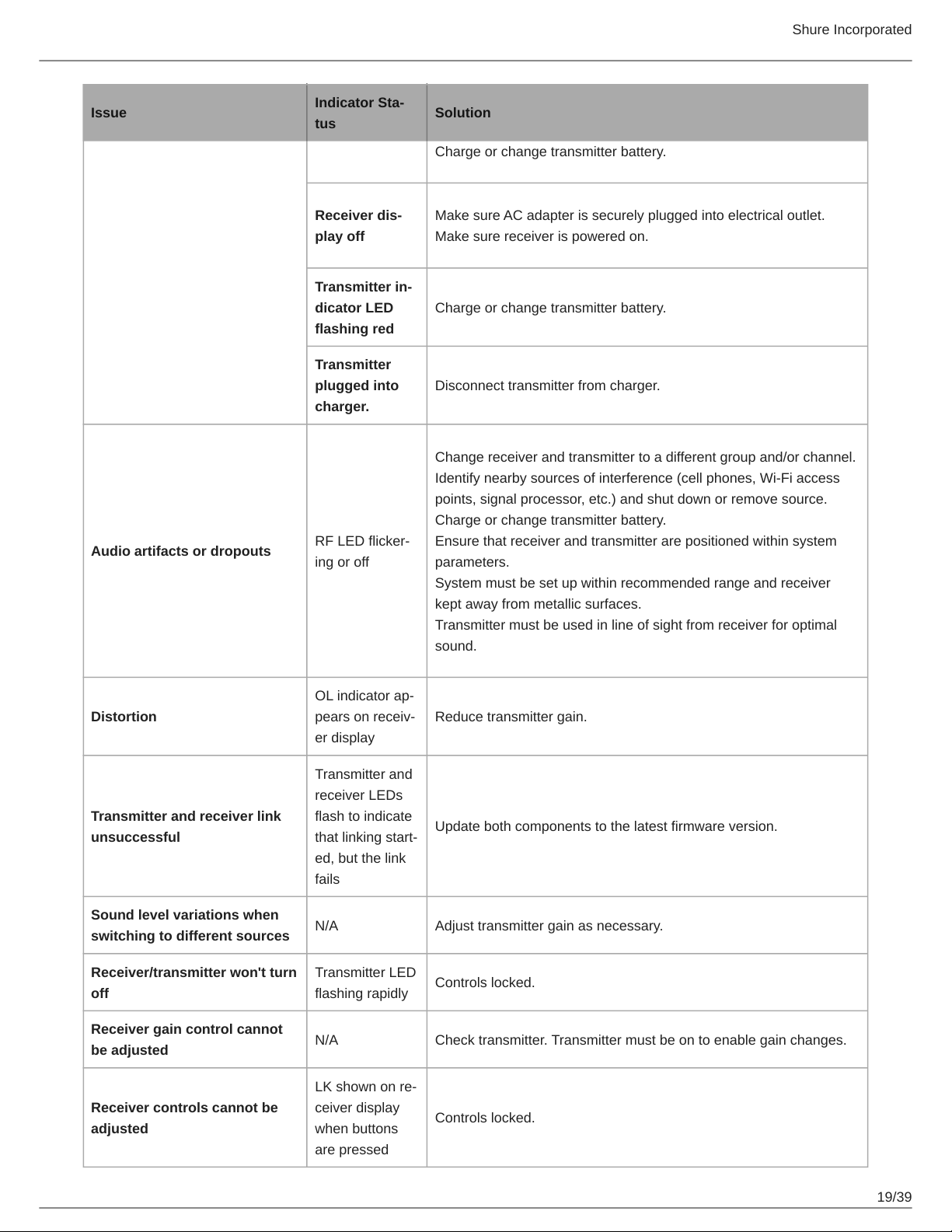
Issue
Indicator Sta
tus
Solution
Charge or change transmitter battery.
Receiver dis
play off
Make sure AC adapter is securely plugged into electrical outlet.
Make sure receiver is powered on.
Transmitter in
dicator LED
flashing red
Charge or change transmitter battery.
Transmitter
plugged into
charger.
Disconnect transmitter from charger.
Audio artifacts or dropouts
RF LED flicker
ing or off
Change receiver and transmitter to a different group and/or channel.
Identify nearby sources of interference (cell phones, Wi-Fi access
points, signal processor, etc.) and shut down or remove source.
Charge or change transmitter battery.
Ensure that receiver and transmitter are positioned within system
parameters.
System must be set up within recommended range and receiver
kept away from metallic surfaces.
Transmitter must be used in line of sight from receiver for optimal
sound.
Distortion
OL indicator ap
pears on receiv
er display
Reduce transmitter gain.
Transmitter and receiver link
unsuccessful
Transmitter and
receiver LEDs
flash to indicate
that linking start
ed, but the link
fails
Update both components to the latest firmware version.
Sound level variations when
switching to different sources
N/A Adjust transmitter gain as necessary.
Receiver/transmitter won't turn
off
Transmitter LED
flashing rapidly
Controls locked.
Receiver gain control cannot
be adjusted
N/A Check transmitter. Transmitter must be on to enable gain changes.
Receiver controls cannot be
adjusted
LK shown on re
ceiver display
when buttons
are pressed
Controls locked.
Shure Incorporated
20/39
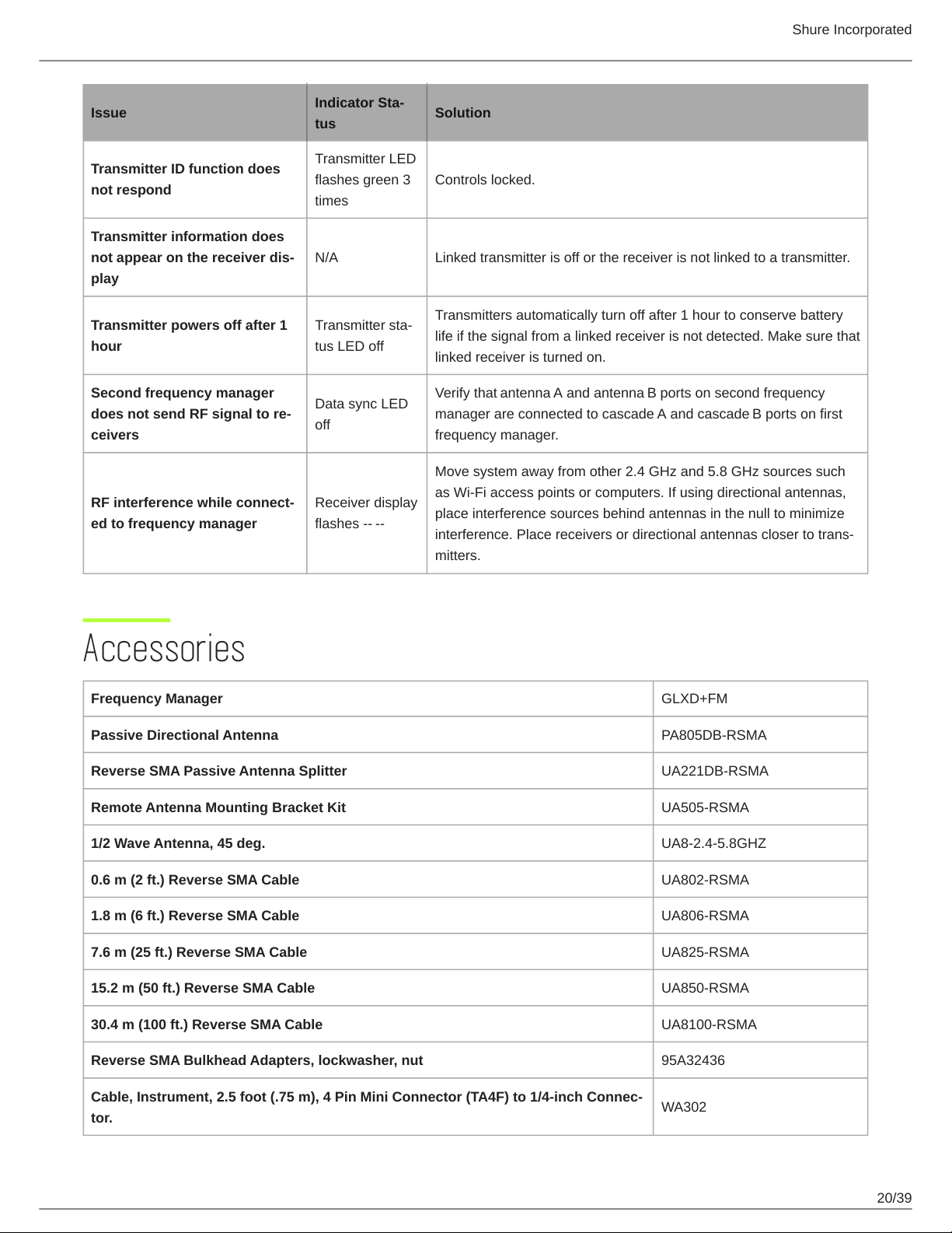
Issue
Indicator Sta
tus
Solution
Transmitter ID function does
not respond
Transmitter LED
flashes green 3
times
Controls locked.
Transmitter information does
not appear on the receiver dis
play
N/A Linked transmitter is off or the receiver is not linked to a transmitter.
Transmitter powers off after 1
hour
Transmitter sta
tus LED off
Transmitters automatically turn off after 1 hour to conserve battery
life if the signal from a linked receiver is not detected. Make sure that
linked receiver is turned on.
Second frequency manager
does not send RF signal to re
ceivers
Data sync LED
off
Verify that antenna A and antenna B ports on second frequency
manager are connected to cascade A and cascade B ports on first
frequency manager.
RF interference while connect
ed to frequency manager
Receiver display
flashes
Move system away from other 2.4 GHz and 5.8 GHz sources such
as Wi-Fi access points or computers. If using directional antennas,
place interference sources behind antennas in the null to minimize
interference. Place receivers or directional antennas closer to trans
mitters.
Accessories
Frequency Manager GLXD+FM
Passive Directional Antenna PA805DB-RSMA
Reverse SMA Passive Antenna Splitter UA221DB-RSMA
Remote Antenna Mounting Bracket Kit UA505-RSMA
1/2 Wave Antenna, 45 deg. UA8-2.4-5.8GHZ
0.6 m (2 ft.) Reverse SMA Cable UA802-RSMA
1.8 m (6 ft.) Reverse SMA Cable UA806-RSMA
7.6 m (25 ft.) Reverse SMA Cable UA825-RSMA
15.2 m (50 ft.) Reverse SMA Cable UA850-RSMA
30.4 m (100 ft.) Reverse SMA Cable UA8100-RSMA
Reverse SMA Bulkhead Adapters, lockwasher, nut 95A32436
Cable, Instrument, 2.5 foot (.75 m), 4 Pin Mini Connector (TA4F) to 1/4inch Connec
tor.
WA302
Shure Incorporated
21/39
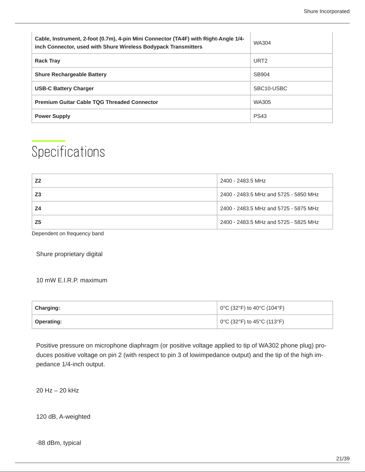
Cable, Instrument, 2-foot (0.7m), 4-pin Mini Connector (TA4F) with Right-Angle 1/4-
inch Connector, used with Shure Wireless Bodypack Transmitters
WA304
Rack Tray URT2
Shure Rechargeable Battery SB904
USB-C Battery Charger SBC10-USBC
Premium Guitar Cable TQG Threaded Connector WA305
Power Supply PS43
Specifications
Tuning Bandwidth
Z2 2400 - 2483.5 MHz
Z3 2400 - 2483.5 MHz and 5725 - 5850 MHz
Z4 2400 - 2483.5 MHz and 5725 - 5875 MHz
Z5 2400 - 2483.5 MHz and 5725 - 5825 MHz
Dependent on frequency band
Transmit Mode
Shure proprietary digital
RF Output Power
10 mW E.I.R.P. maximum
Ambient Temperature Range
Charging: 0°C (32°F) to 40°C (104°F)
Operating: 0°C (32°F) to 45°C (113°F)
Polarity
Positive pressure on microphone diaphragm (or positive voltage applied to tip of WA302 phone plug) pro
duces positive voltage on pin 2 (with respect to pin 3 of lowimpedance output) and the tip of the high im
pedance 1/4-inch output.
Audio Frequency Response
20 Hz – 20 kHz
Dynamic Range
120 dB, A-weighted
RF Sensitivity
-88 dBm, typical
Shure Incorporated
22/39
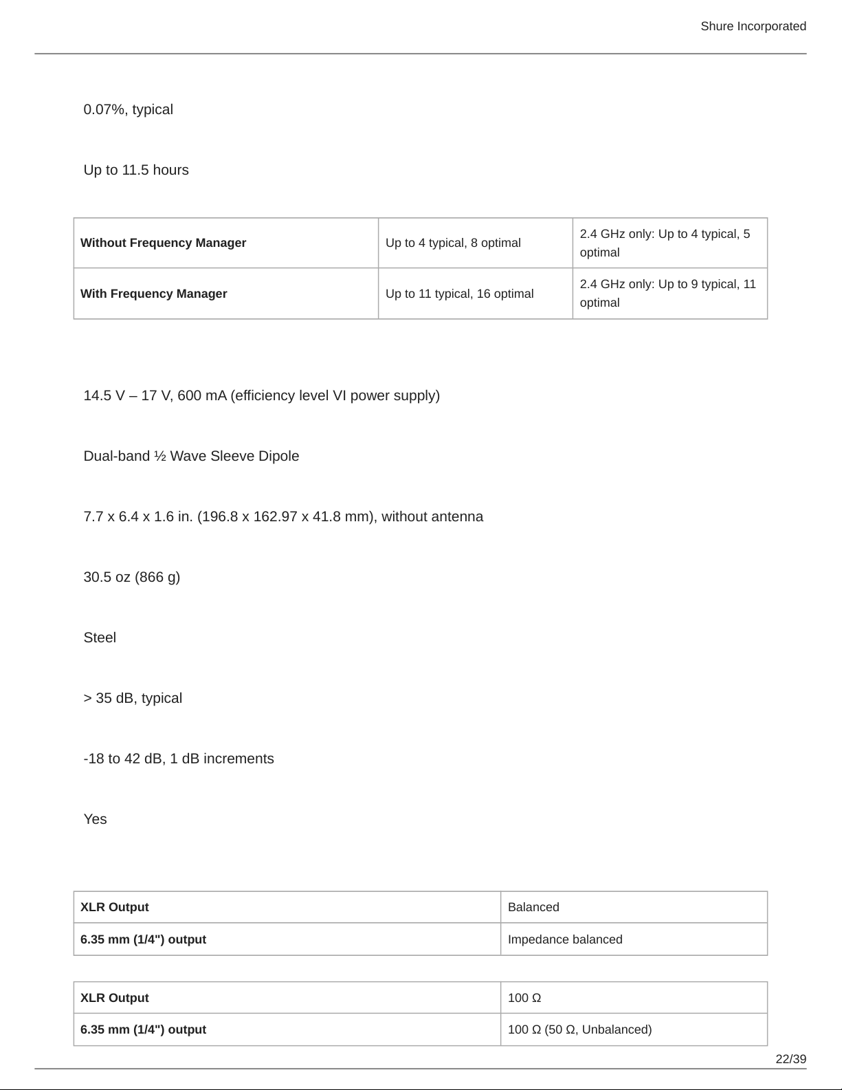
Total Harmonic Distortion
0.07%, typical
Battery Life
Up to 11.5 hours
Channel Count
Without Frequency Manager Up to 4 typical, 8 optimal
2.4 GHz only: Up to 4 typical, 5
optimal
With Frequency Manager Up to 11 typical, 16 optimal
2.4 GHz only: Up to 9 typical, 11
optimal
GLXD4R+
Power Requirements
14.5 V – 17 V, 600 mA (efficiency level VI power supply)
Antenna Type
Dual-band ½ Wave Sleeve Dipole
Dimensions
7.7 x 6.4 x 1.6 in. (196.8 x 162.97 x 41.8 mm), without antenna
Weight
30.5 oz (866 g)
Housing
Steel
Spurious Rejection
> 35 dB, typical
Gain Adjustment Range
-18 to 42 dB, 1 dB increments
Phantom Power Protection
Yes
AUDIO OUTPUT:
Configuration
XLR Output Balanced
6.35 mm (1/4") output Impedance balanced
Impedance
XLR Output 100 Ω
6.35 mm (1/4") output 100 Ω (50 Ω, Unbalanced)
Shure Incorporated
23/39
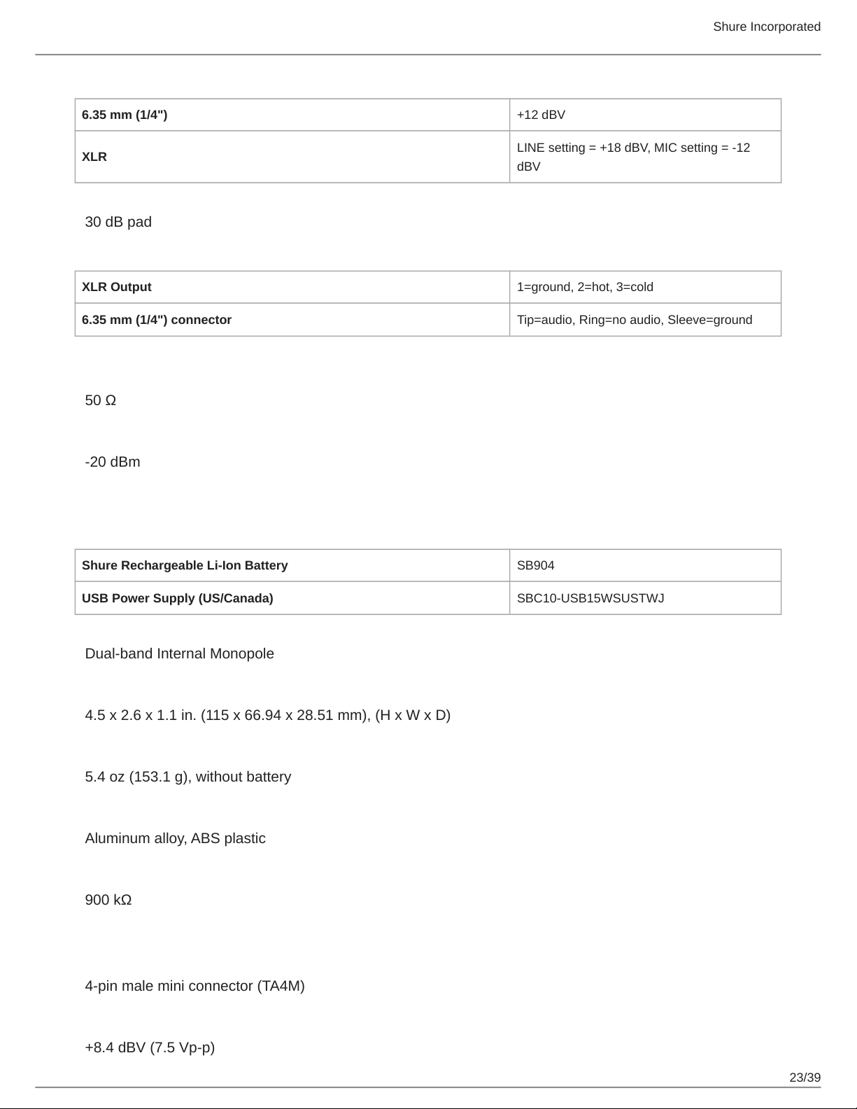
Full Scale Output
6.35 mm (1/4") +12 dBV
XLR
LINE setting = +18 dBV, MIC setting = -12
dBV
Mic/Line Switch
30 dB pad
Pin Assignments
XLR Output 1=ground, 2=hot, 3=cold
6.35 mm (1/4") connector Tip=audio, Ring=no audio, Sleeve=ground
RECEIVER ANTENNA INPUT:
Impedance
50 Ω
Maximum Input Level
-20 dBm
GLXD1+
Power Requirements
Shure Rechargeable Li-Ion Battery SB904
USB Power Supply (US/Canada) SBC10-USB15WSUSTWJ
Antenna Type
Dual-band Internal Monopole
Dimensions
4.5 x 2.6 x 1.1 in. (115 x 66.94 x 28.51 mm), (H x W x D)
Weight
5.4 oz (153.1 g), without battery
Housing
Aluminum alloy, ABS plastic
Input Impedance
900 kΩ
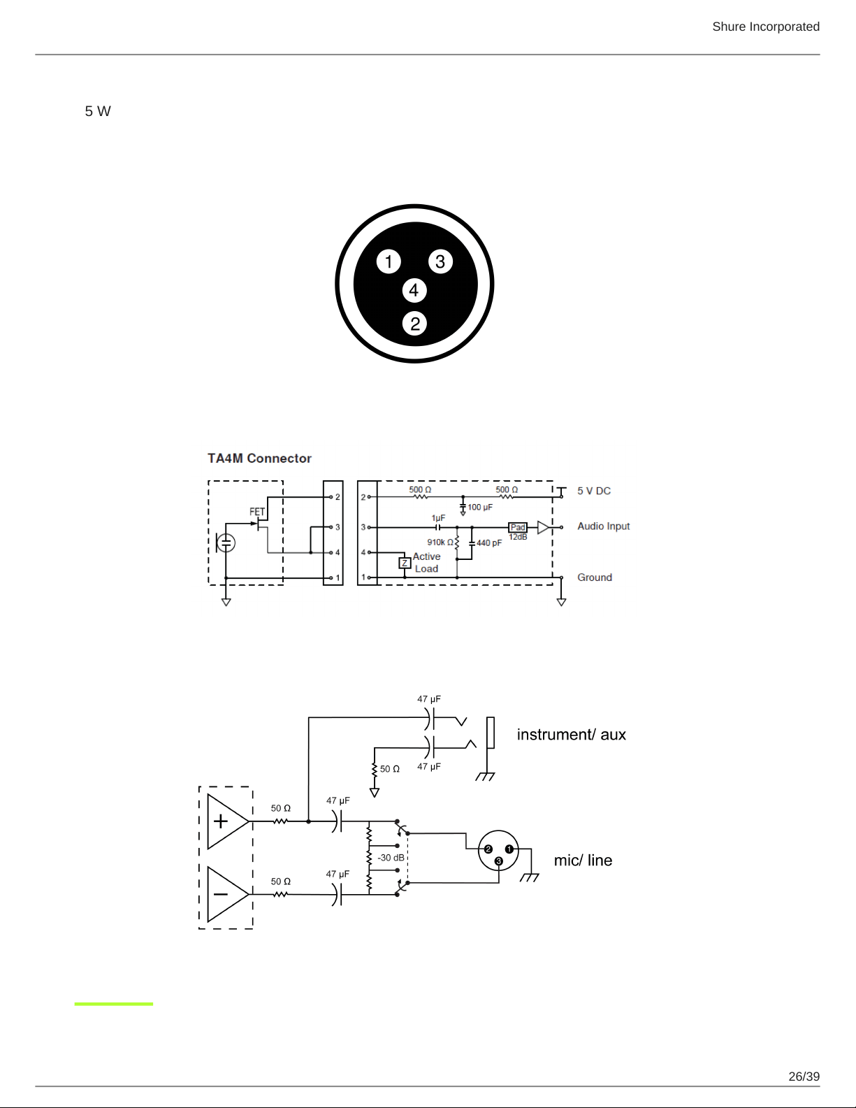
TX INPUT:
Connector
4-pin male mini connector (TA4M)
Maximum Input Level
+8.4 dBV (7.5 Vp-p)
Shure Incorporated
24/39
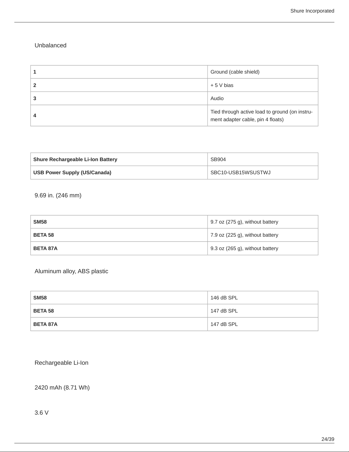
Configuration
Unbalanced
Pin Assignments
1 Ground (cable shield)
2 + 5 V bias
3 Audio
4
Tied through active load to ground (on instru
ment adapter cable, pin 4 floats)
GLXD2+
Power Requirements
Shure Rechargeable Li-Ion Battery SB904
USB Power Supply (US/Canada) SBC10-USB15WSUSTWJ
Dimensions
9.69 in. (246 mm)
Weight
SM58 9.7 oz (275 g), without battery
BETA 58 7.9 oz (225 g), without battery
BETA 87A 9.3 oz (265 g), without battery
Housing
Aluminum alloy, ABS plastic
Maximum Input Level
SM58 146 dB SPL
BETA 58 147 dB SPL
BETA 87A 147 dB SPL
SB904
Battery Type
Rechargeable Li-Ion
Nominal Capacity
2420 mAh (8.71 Wh)
Nominal Voltage
3.6 V
Shure Incorporated
25/39
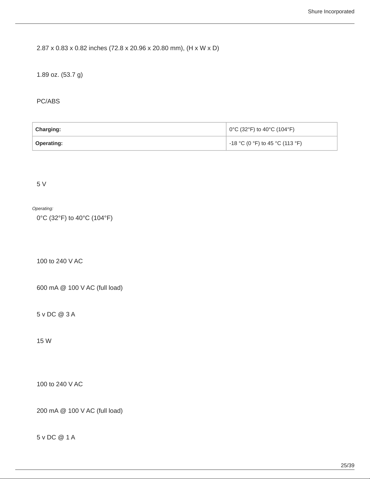
Dimensions
2.87 x 0.83 x 0.82 inches (72.8 x 20.96 x 20.80 mm), (H x W x D)
Weight
1.89 oz. (53.7 g)
Housing
PC/ABS
Ambient Temperature Range
Charging: 0°C (32°F) to 40°C (104°F)
Operating: 18 °C (0 °F) to 45 °C (113 °F)
SBC10-904
DC Input Voltage
5 V
Ambient Temperature Range
Operating:
0°C (32°F) to 40°C (104°F)
SBC10-USB15W Power Supply
Input Voltage Range
100 to 240 V AC
Maximum Input Power
600 mA @ 100 V AC (full load)
Output Voltage
5 v DC @ 3 A
Maximum Output Power
15 W
SBC10-USB Power Supply
Input Voltage Range
100 to 240 V AC
Maximum Input Power
200 mA @ 100 V AC (full load)
Output Voltage
5 v DC @ 1 A
Shure Incorporated
26/39
Maximum Output Power
5 W
Diagrams
Shure Incorporated
27/39
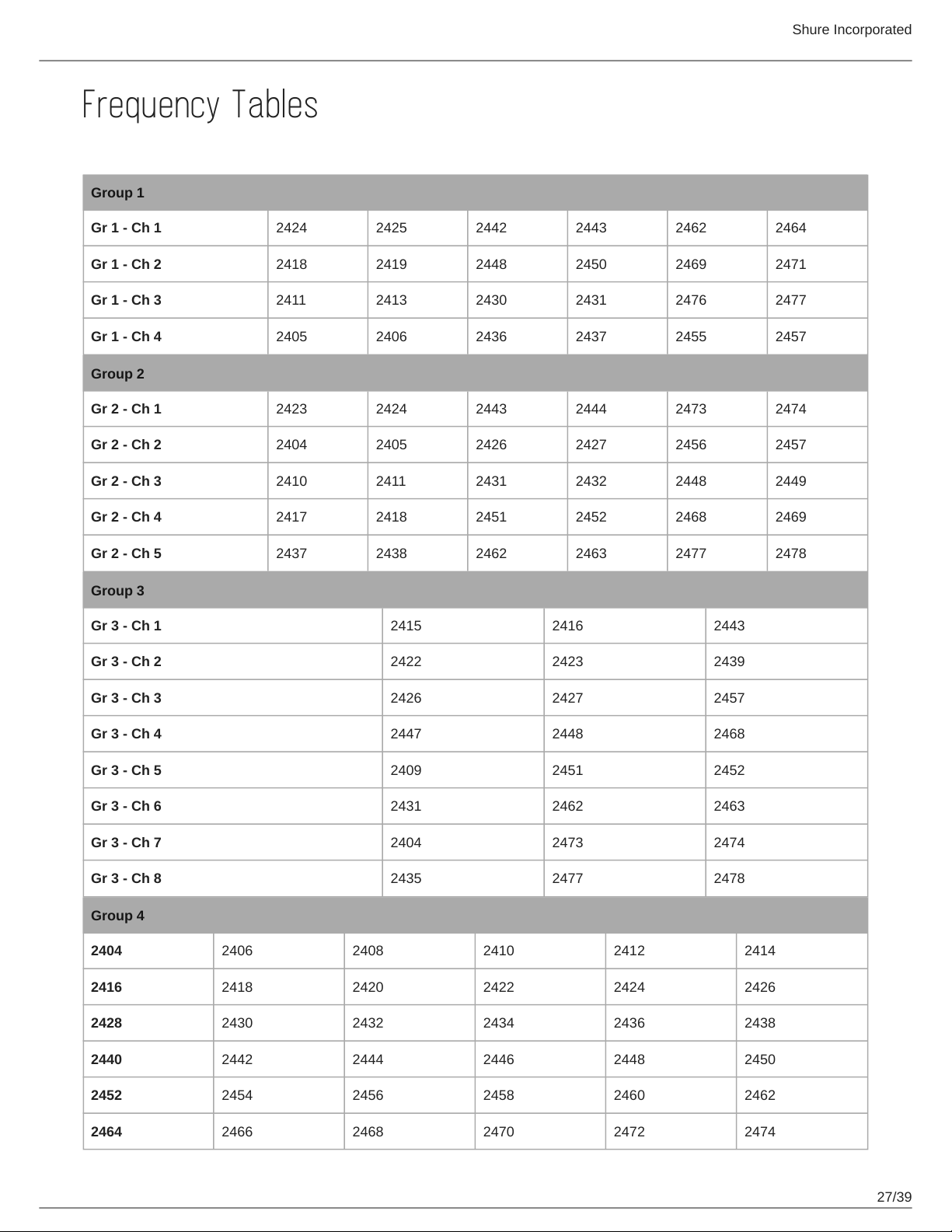
Frequency Tables
Z2 (2.4 GHz only)
Group 1
Gr 1 - Ch 1 2424 2425 2442 2443 2462 2464
Gr 1 - Ch 2 2418 2419 2448 2450 2469 2471
Gr 1 - Ch 3 2411 2413 2430 2431 2476 2477
Gr 1 - Ch 4 2405 2406 2436 2437 2455 2457
Group 2
Gr 2 - Ch 1 2423 2424 2443 2444 2473 2474
Gr 2 - Ch 2 2404 2405 2426 2427 2456 2457
Gr 2 - Ch 3 2410 2411 2431 2432 2448 2449
Gr 2 - Ch 4 2417 2418 2451 2452 2468 2469
Gr 2 - Ch 5 2437 2438 2462 2463 2477 2478
Group 3
Gr 3 - Ch 1 2415 2416 2443
Gr 3 - Ch 2 2422 2423 2439
Gr 3 - Ch 3 2426 2427 2457
Gr 3 - Ch 4 2447 2448 2468
Gr 3 - Ch 5 2409 2451 2452
Gr 3 - Ch 6 2431 2462 2463
Gr 3 - Ch 7 2404 2473 2474
Gr 3 - Ch 8 2435 2477 2478
Group 4
2404 2406 2408 2410 2412 2414
2416 2418 2420 2422 2424 2426
2428 2430 2432 2434 2436 2438
2440 2442 2444 2446 2448 2450
2452 2454 2456 2458 2460 2462
2464 2466 2468 2470 2472 2474
Shure Incorporated
28/39
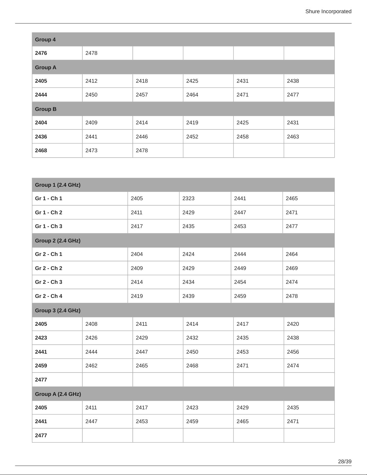
Group 4
2476 2478
Group A
2405 2412 2418 2425 2431 2438
2444 2450 2457 2464 2471 2477
Group B
2404 2409 2414 2419 2425 2431
2436 2441 2446 2452 2458 2463
2468 2473 2478
Z3
Group 1 (2.4 GHz)
Gr 1 - Ch 1 2405 2323 2441 2465
Gr 1 - Ch 2 2411 2429 2447 2471
Gr 1 - Ch 3 2417 2435 2453 2477
Group 2 (2.4 GHz)
Gr 2 - Ch 1 2404 2424 2444 2464
Gr 2 - Ch 2 2409 2429 2449 2469
Gr 2 - Ch 3 2414 2434 2454 2474
Gr 2 - Ch 4 2419 2439 2459 2478
Group 3 (2.4 GHz)
2405 2408 2411 2414 2417 2420
2423 2426 2429 2432 2435 2438
2441 2444 2447 2450 2453 2456
2459 2462 2465 2468 2471 2474
2477
Group A (2.4 GHz)
2405 2411 2417 2423 2429 2435
2441 2447 2453 2459 2465 2471
2477
Shure Incorporated
29/39
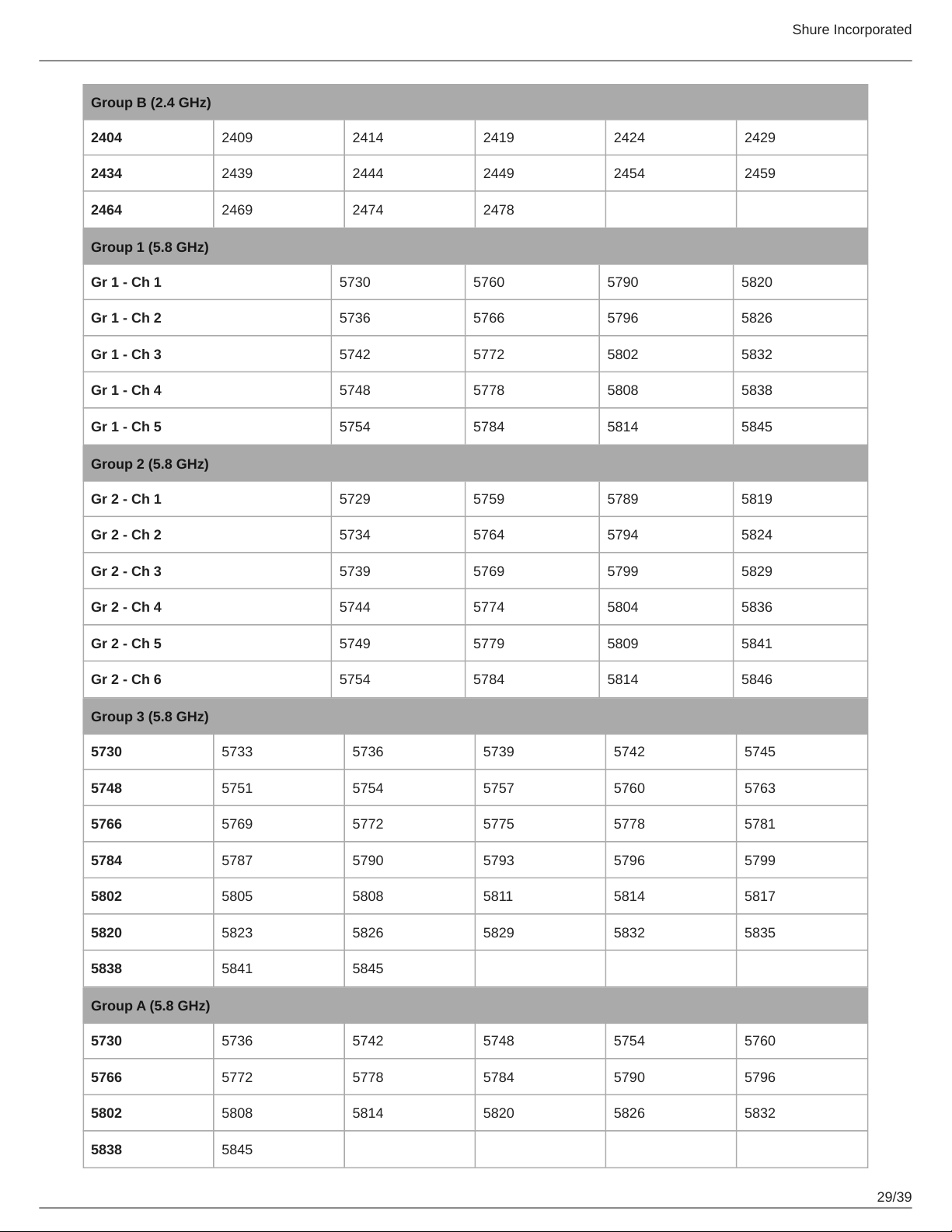
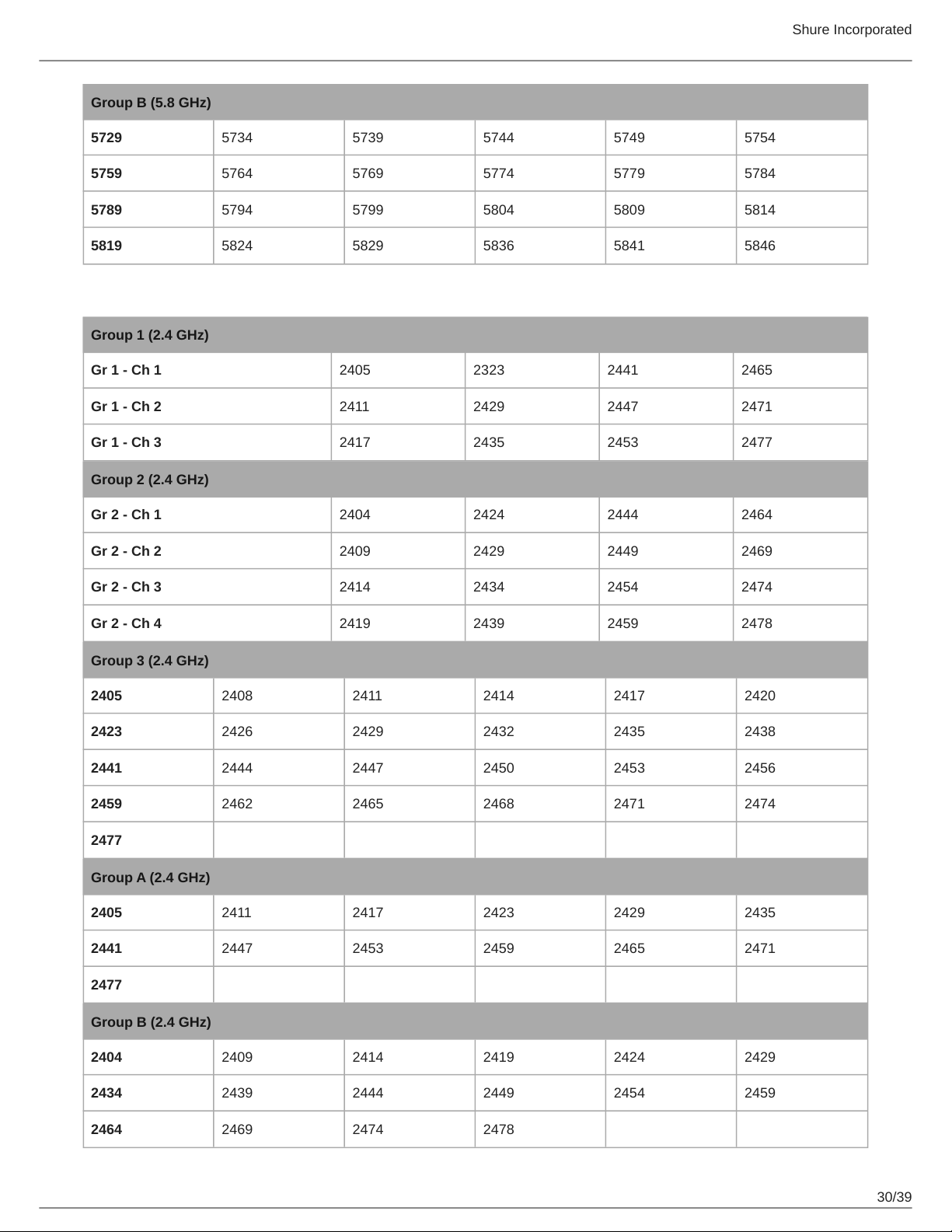
Group B (2.4 GHz)
2404 2409 2414 2419 2424 2429
2434 2439 2444 2449 2454 2459
2464 2469 2474 2478
Group 1 (5.8 GHz)
Gr 1 - Ch 1 5730 5760 5790 5820
Gr 1 - Ch 2 5736 5766 5796 5826
Gr 1 - Ch 3 5742 5772 5802 5832
Gr 1 - Ch 4 5748 5778 5808 5838
Gr 1 - Ch 5 5754 5784 5814 5845
Group 2 (5.8 GHz)
Gr 2 - Ch 1 5729 5759 5789 5819
Gr 2 - Ch 2 5734 5764 5794 5824
Gr 2 - Ch 3 5739 5769 5799 5829
Gr 2 - Ch 4 5744 5774 5804 5836
Gr 2 - Ch 5 5749 5779 5809 5841
Gr 2 - Ch 6 5754 5784 5814 5846
Group 3 (5.8 GHz)
5730 5733 5736 5739 5742 5745
5748 5751 5754 5757 5760 5763
5766 5769 5772 5775 5778 5781
5784 5787 5790 5793 5796 5799
5802 5805 5808 5811 5814 5817
5820 5823 5826 5829 5832 5835
5838 5841 5845
Group A (5.8 GHz)
5730 5736 5742 5748 5754 5760
5766 5772 5778 5784 5790 5796
5802 5808 5814 5820 5826 5832
5838 5845
Shure Incorporated
30/39
Group B (5.8 GHz)
5729 5734 5739 5744 5749 5754
5759 5764 5769 5774 5779 5784
5789 5794 5799 5804 5809 5814
5819 5824 5829 5836 5841 5846
Z4
Group 1 (2.4 GHz)
Gr 1 - Ch 1 2405 2323 2441 2465
Gr 1 - Ch 2 2411 2429 2447 2471
Gr 1 - Ch 3 2417 2435 2453 2477
Group 2 (2.4 GHz)
Gr 2 - Ch 1 2404 2424 2444 2464
Gr 2 - Ch 2 2409 2429 2449 2469
Gr 2 - Ch 3 2414 2434 2454 2474
Gr 2 - Ch 4 2419 2439 2459 2478
Group 3 (2.4 GHz)
2405 2408 2411 2414 2417 2420
2423 2426 2429 2432 2435 2438
2441 2444 2447 2450 2453 2456
2459 2462 2465 2468 2471 2474
2477
Group A (2.4 GHz)
2405 2411 2417 2423 2429 2435
2441 2447 2453 2459 2465 2471
2477
Group B (2.4 GHz)
2404 2409 2414 2419 2424 2429
2434 2439 2444 2449 2454 2459
2464 2469 2474 2478
Shure Incorporated
31/39
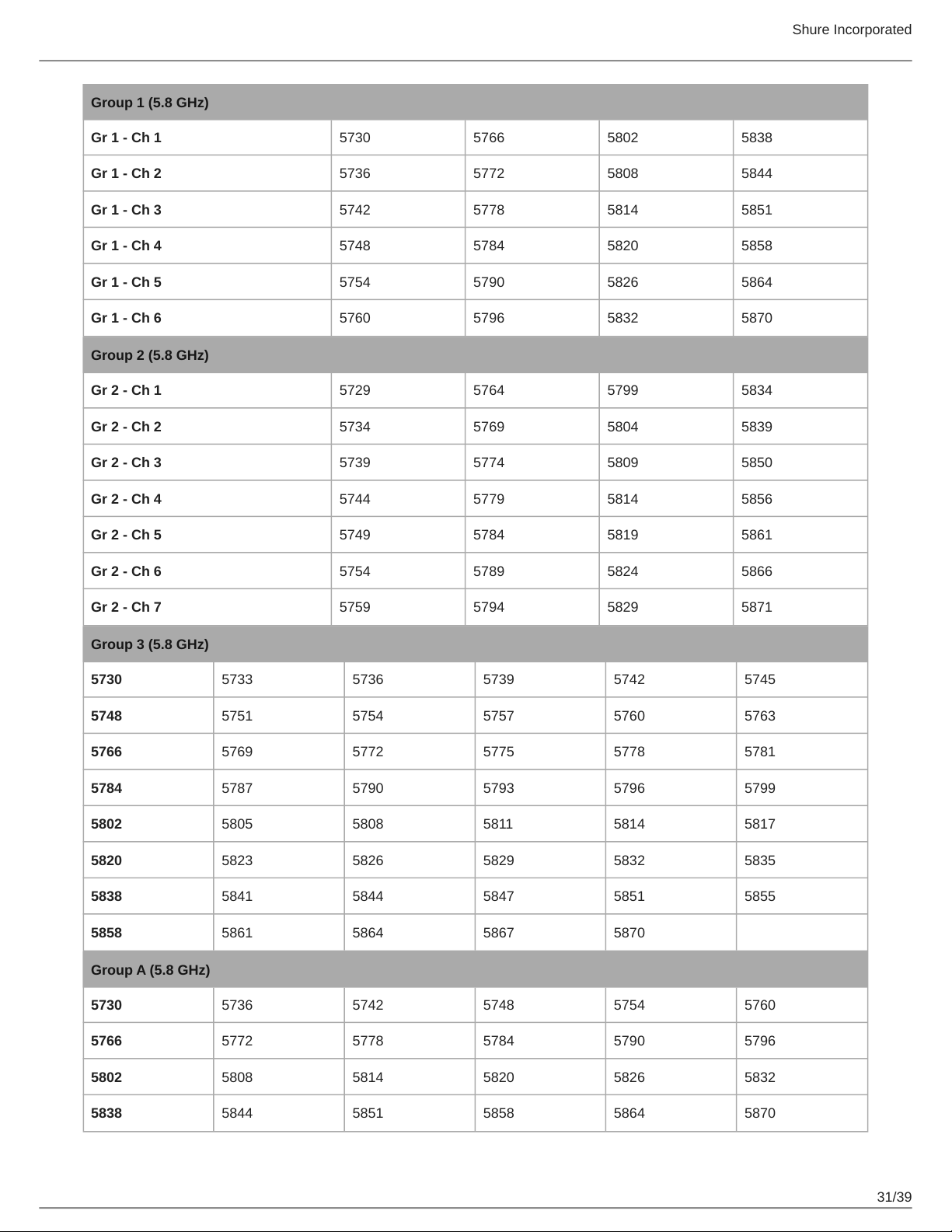
Group 1 (5.8 GHz)
Gr 1 - Ch 1 5730 5766 5802 5838
Gr 1 - Ch 2 5736 5772 5808 5844
Gr 1 - Ch 3 5742 5778 5814 5851
Gr 1 - Ch 4 5748 5784 5820 5858
Gr 1 - Ch 5 5754 5790 5826 5864
Gr 1 - Ch 6 5760 5796 5832 5870
Group 2 (5.8 GHz)
Gr 2 - Ch 1 5729 5764 5799 5834
Gr 2 - Ch 2 5734 5769 5804 5839
Gr 2 - Ch 3 5739 5774 5809 5850
Gr 2 - Ch 4 5744 5779 5814 5856
Gr 2 - Ch 5 5749 5784 5819 5861
Gr 2 - Ch 6 5754 5789 5824 5866
Gr 2 - Ch 7 5759 5794 5829 5871
Group 3 (5.8 GHz)
5730 5733 5736 5739 5742 5745
5748 5751 5754 5757 5760 5763
5766 5769 5772 5775 5778 5781
5784 5787 5790 5793 5796 5799
5802 5805 5808 5811 5814 5817
5820 5823 5826 5829 5832 5835
5838 5841 5844 5847 5851 5855
5858 5861 5864 5867 5870
Group A (5.8 GHz)
5730 5736 5742 5748 5754 5760
5766 5772 5778 5784 5790 5796
5802 5808 5814 5820 5826 5832
5838 5844 5851 5858 5864 5870
Shure Incorporated
32/39
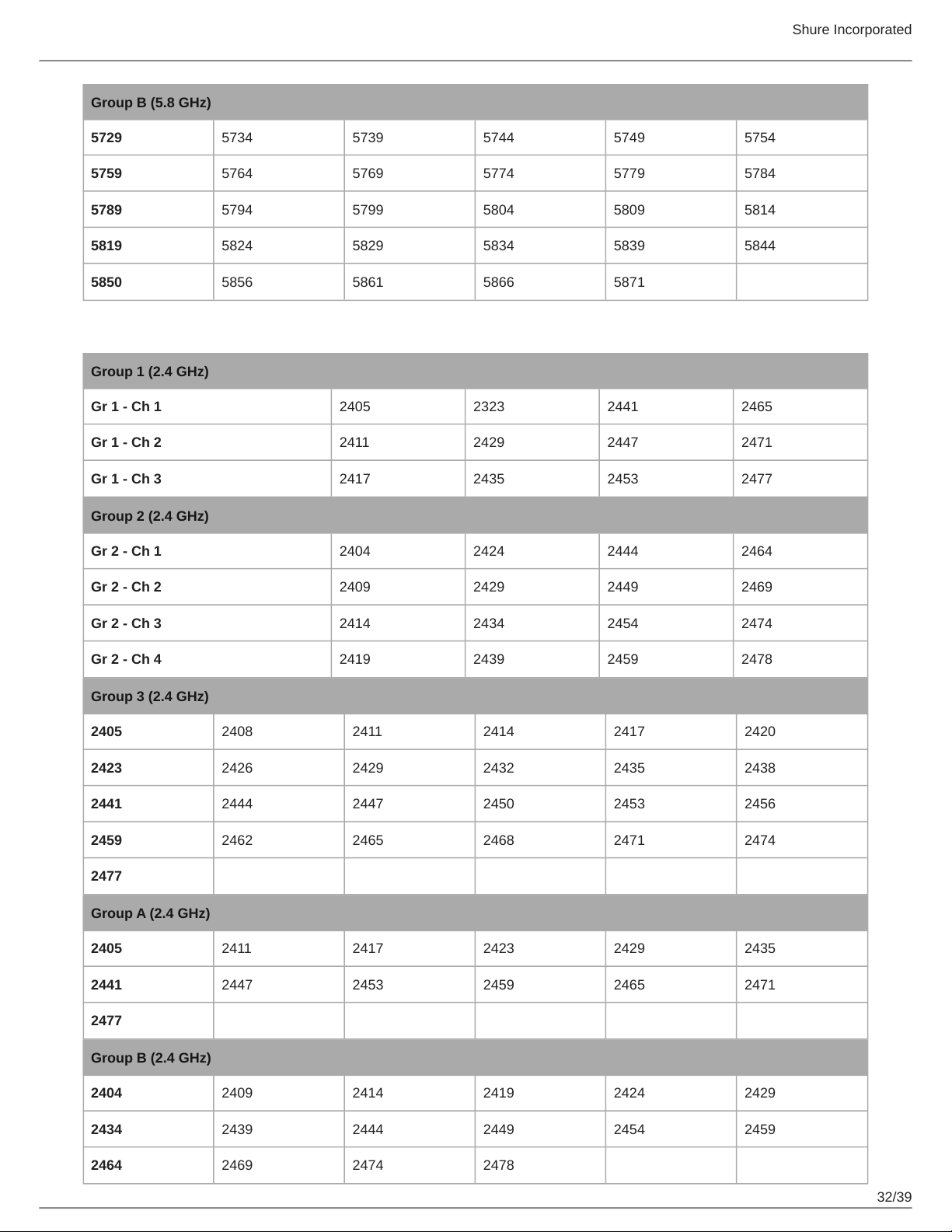
Group B (5.8 GHz)
5729 5734 5739 5744 5749 5754
5759 5764 5769 5774 5779 5784
5789 5794 5799 5804 5809 5814
5819 5824 5829 5834 5839 5844
5850 5856 5861 5866 5871
Z5
Group 1 (2.4 GHz)
Gr 1 - Ch 1 2405 2323 2441 2465
Gr 1 - Ch 2 2411 2429 2447 2471
Gr 1 - Ch 3 2417 2435 2453 2477
Group 2 (2.4 GHz)
Gr 2 - Ch 1 2404 2424 2444 2464
Gr 2 - Ch 2 2409 2429 2449 2469
Gr 2 - Ch 3 2414 2434 2454 2474
Gr 2 - Ch 4 2419 2439 2459 2478
Group 3 (2.4 GHz)
2405 2408 2411 2414 2417 2420
2423 2426 2429 2432 2435 2438
2441 2444 2447 2450 2453 2456
2459 2462 2465 2468 2471 2474
2477
Group A (2.4 GHz)
2405 2411 2417 2423 2429 2435
2441 2447 2453 2459 2465 2471
2477
Group B (2.4 GHz)
2404 2409 2414 2419 2424 2429
2434 2439 2444 2449 2454 2459
2464 2469 2474 2478
Shure Incorporated
33/39
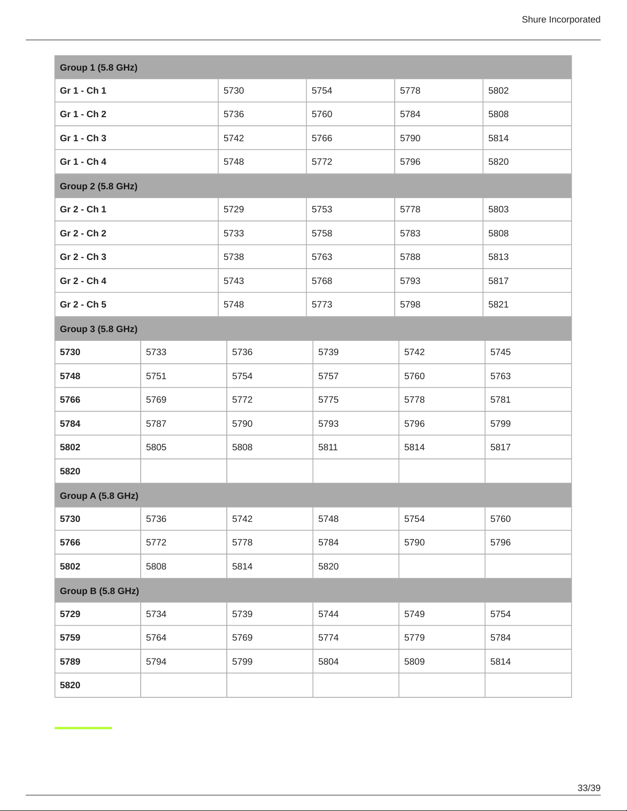
Group 1 (5.8 GHz)
Gr 1 - Ch 1 5730 5754 5778 5802
Gr 1 - Ch 2 5736 5760 5784 5808
Gr 1 - Ch 3 5742 5766 5790 5814
Gr 1 - Ch 4 5748 5772 5796 5820
Group 2 (5.8 GHz)
Gr 2 - Ch 1 5729 5753 5778 5803
Gr 2 - Ch 2 5733 5758 5783 5808
Gr 2 - Ch 3 5738 5763 5788 5813
Gr 2 - Ch 4 5743 5768 5793 5817
Gr 2 - Ch 5 5748 5773 5798 5821
Group 3 (5.8 GHz)
5730 5733 5736 5739 5742 5745
5748 5751 5754 5757 5760 5763
5766 5769 5772 5775 5778 5781
5784 5787 5790 5793 5796 5799
5802 5805 5808 5811 5814 5817
5820
Group A (5.8 GHz)
5730 5736 5742 5748 5754 5760
5766 5772 5778 5784 5790 5796
5802 5808 5814 5820
Group B (5.8 GHz)
5729 5734 5739 5744 5749 5754
5759 5764 5769 5774 5779 5784
5789 5794 5799 5804 5809 5814
5820
Shure Incorporated
34/39
1.
2.
3.
4.
5.
6.
7.
8.
9.
10.
11.
12.
13.
14.
15.
16.
17.
18.
19.
20.
21.
IMPORTANT SAFETY INSTRUCTIONS
READ these instructions.
KEEP these instructions.
HEED all warnings.
FOLLOW all instructions.
DO NOT use this apparatus near water.
CLEAN ONLY with dry cloth.
DO NOT block any ventilation openings. Allow sufficient distances for adequate ventilation and install in accordance
with the manufacturer’s instructions.
DO NOT install near any heat sources such as open flames, radiators, heat registers, stoves, or other apparatus (in
cluding amplifiers) that produce heat. Do not place any open flame sources on the product.
DO NOT defeat the safety purpose of the polarized or grounding type plug. A polarized plug has two blades with one
wider than the other. A grounding type plug has two blades and a third grounding prong. The wider blade or the third
prong are provided for your safety. If the provided plug does not fit into your outlet, consult an electrician for replace
ment of the obsolete outlet.
PROTECT the power cord from being walked on or pinched, particularly at plugs, convenience receptacles, and the
point where they exit from the apparatus.
ONLY USE attachments/accessories specified by the manufacturer.
USE only with a cart, stand, tripod, bracket, or table specified by the manufacturer, or sold with the apparatus. When a
cart is used, use caution when moving the cart/apparatus combination to avoid injury from tip-over.
UNPLUG this apparatus during lightning storms or when unused for long periods of time.
REFER all servicing to qualified service personnel. Servicing is required when the apparatus has been damaged in any
way, such as power supply cord or plug is damaged, liquid has been spilled or objects have fallen into the apparatus,
the apparatus has been exposed to rain or moisture, does not operate normally, or has been dropped.
DO NOT expose the apparatus to dripping and splashing. DO NOT put objects filled with liquids, such as vases, on the
apparatus.
The MAINS plug or an appliance coupler shall remain readily operable.
The airborne noise of the Apparatus does not exceed 70dB (A).
Apparatus with CLASS I construction shall be connected to a MAINS socket outlet with a protective earthing connec
tion.
To reduce the risk of fire or electric shock, do not expose this apparatus to rain or moisture.
Do not attempt to modify this product. Doing so could result in personal injury and/or product failure.
Operate this product within its specified operating temperature range.
This symbol indicates that dangerous voltage constituting a risk of electric shock is present within this unit.
This symbol indicates that there are important operating and maintenance instructions in the literature accom
panying this unit.
In the European Union and the United Kingdom, this label indicates that the batteries in this product should be collected sepa
rately and not be disposed of with household waste. Substances in batteries can have a potential negative impact on health
Shure Incorporated
35/39
•
•
•
•
•
•
•
•
•
•
•
•
•
•
•
•
•
•
•
•
and environment and you have a role in recycling waste batteries thus contributing to the protection, preservation, and im
provement of the quality of the environment. You should contact your local authority or retailer for details of the collection and
recycling schemes available.
Please consider the environment, electric products and packaging are part of regional recycling schemes and do not belong to
regular household waste.
WARNING
Battery packs may explode or release toxic materials. Risk of fire or burns. Do not open, crush, modify, disassemble, heat
above 140°F (60°C), or incinerate.
Follow instructions from manufacturer
Only use Shure charger to recharge Shure rechargeable batteries
WARNING: Danger of explosion if battery incorrectly replaced. Replace only with same or equivalent type.
Never put batteries in mouth. If swallowed, contact your physician or local poison control center
Do not short circuit; may cause burns or catch fire
Do not charge or use battery packs other than Shure rechargeable batteries
Dispose of battery packs properly. Check with local vendor for proper disposal of used battery packs.
Batteries (battery pack or batteries installed) shall not be exposed to excessive heat such as sunshine, fire or the like
Do not immerse the battery in liquid such as water, beverages, or other fluids.
Do not attach or insert battery with polarity reversed.
Keep away from small children.
Do not use abnormal batteries.
Pack the battery securely for transport.
Note:
This equipment is intended to be used in professional audio applications.
EMC conformance is based on the use of supplied and recommended cable types. The use of other cable types may de
grade EMC performance.
Use this battery charger only with the Shure charging modules and battery packs for which it is designed. Use with other
than the specified modules and battery packs may increase the risk of fire or explosion.
Changes or modifications not expressly approved by Shure Incorporated could void your authority to operate this equip
ment.
Information to the user
This equipment has been tested and found to comply with the limits for a Class B digital device, pursuant to part 15 of the FCC
Rules. This equipment generates, uses, and can radiate radio frequency energy and, if not installed and used in accordance
with the manufacturer's instruction manual, may cause interference with radio and television reception.
Notice: The FCC regulations provide that changes or modifications not expressly approved by Shure Incorporated could void
your authority to operate this equipment.
These limits are designed to provide reasonable protection against harmful interference in a residential installation. This equip
ment generates, uses, and can radiate radio frequency energy and, if not installed and used in accordance with the instruc
tions, may cause harmful interference to radio communications. However, there is no guarantee that interference will not occur
in a particular installation. If this equipment does cause harmful interference to radio or television reception, which can be de
termined by turning the equipment off and on, the user is encouraged to try to correct the interference by one or more of the
following measures:
Reorient or relocate the receiving antenna.
Increase the separation between the equipment and the receiver.
Shure Incorporated
36/39
•
•
1.
2.
1.
2.
1.
2.
Connect the equipment to an outlet on a circuit different from that to which the receiver is connected.
Consult the dealer or an experienced radio/TV technician for help.
This device complies with part 15 of the FCC Rules. Operation is subject to the following two conditions:
This device may not cause harmful interference.
This device must accept any interference received, including interference that may cause undesired operation.
Certified under FCC Part 15.
Shure has determined that this product is a Class B harmonized product. The following sections provide country-specific EMC/
EMI or product safety information.
Certifications
FCC ID: DD4GLXD4RZ3, DD4GLXD1Z3, DD4GLXD2Z3 IC: 616A-GLXD4RZ3, 616A-GLXD1Z3, 616A-GLXD2Z3
CAN ICES-003 (B)/NMB-003(B)
Changes or modifications not expressly approved by the manufacturer could void the user’s authority to operate the
equipment.
The antenna(s) must be installed such that a minimum separation distance of 20 cm is maintained between the radiator (anten
na) and all persons at all times.
La ou les antennes doivent être installées de telle façon qu'une distance de séparation minimum de 20 cm soit maintenue en
tre le radiateur (antenne) et toute personne à tout moment.
This equipment complies with FCC radiation exposure limits set forth for an uncontrolled environment. This equipment should
be installed and operated with minimum distance 20 cm between the radiator & your body.
This product meets the applicable Innovation, Science and Economic Development Canada technical specifications. Certified
by ISED in Canada under RSS-247 and RSS-GEN.
This device contains licenceexempt transmitter(s)/receiver(s) that comply with Innovation, Science and Economic Develop
ment Canada’s licenceexempt RSS(s). Operation is subject to the following two conditions:
This device may not cause interference.
This device must accept any interference, including interference that may cause undesired operation of the device.
L’émetteur/récepteur exempt de licence contenu dans le présent appareil est conforme aux CNR d’Innovation, Sciences et
Développement économique Canada applicables aux appareils radio exempts de licence. L’exploitation est autorisée aux deux
conditions suivantes :
L’appareil ne doit pas produire de brouillage;
L’appareil doit accepter tout brouillage radioélectrique subi, même si le brouillage est susceptible d’en compromettre le
fonctionnement.
This equipment complies with FCC and ISED radiation exposure limits set forth for an uncontrolled environment. End user
must follow the specific operating instructions for satisfying RF exposure compliance. This transmitter must not be co-located
or operating in conjunction with any other antenna or transmitter.
Cet équipement est conforme aux limites d’exposition aux rayonnements ISED établies pour un environnement non contrôlé.
L’utilisateur final doit suivre les instructions spécifiques pour satisfaire les normes. Cet émetteur ne doit pas être coimplanté ou
fonctionner en conjonction avec toute autre antenne ou transmetteur.
La operación de este equipo está sujeta a las siguientes dos condiciones: (1) es posible que este equipo o dispositivo no
cause interferencia perjudicial y (2) este equipo o dispositivo debe aceptar cualquier interferencia, incluyendo la que pueda
causar su operación no deseada.
Shure Incorporated
37/39
1.
2.
3.
1.
2.
3.
Este equipamento não tem direito à proteção contra interferência prejudicial e não pode causar interferência em sistemas dev
idamente autorizados. Para maiores informações, consulte o site da ANATEL – http://www.anatel.gov.br.
해당 무선설비는 전파혼신 가능성이 있으므로 인명안전과 관련된 서비스는 할 수 없음
取得審驗證明之低功率射頻器材,非經核准,公司、商號或使用者均不得擅自變更頻率、加大功率或變更原設計之特性及
功能。低功率射頻器材之使用不得影響飛航安全及干擾合法通信;經發現有干擾現象時,應立即停用,並改善至無干擾時
方得繼續使用。前述合法通信,指依電信管理法規定作業之無線電通信。低功率射頻器材須忍受合法通信或工業、科學及
醫療用電波輻射性電機設備之干擾。
應避免影響附近雷達系統之操作。
高增益指向性天線只得應用於固定式點對點系統。
เครื่องโทรคมนาคมและอุปกรณ์นี้มีความสอดคล้องตามมาตรฐานหรือข้อกำหนดทางเทคนิคของ กสทช.
Paraguay Distributor: Microsystems S.R.L., Senador Long 664 c/Dr. Lilio, Asunción, Paraguay
Connection and use of this communications equipment is permitted by the Nigerian Communications Commission.
運用に際しての注意
この機器の使用周波数帯では、電子レンジ等の産業・科学・医療用機器のほか工場の製造ライン等で使用されている移動体識別用の
構内無線局(免許を要する無線局)及び特定小電力無線局(免許を要しない無線局)並びにアマチュア無線局(免許を要する無
線局)が運用されています。
この機器を使用する前に、近くで移動体識別用の構内無線局及び特定小電力無線局並びにアマ チュア無線局が運用さ
れていないことを確認して下さい。
万一、この機器から移動体識別用の構内無線局に対して有害な電波干渉の事例が発生した場合には、 速やかに使用周波
数を変更するか又は電波の発射を停止した上、下記連絡先にご連絡頂き、混 信回避のための処置等(例えば、パーティ
ションの設置など)についてご相談して下さい。
その他、この機器から移動体識別用の特定小電力無線局あるいはアマチュア無線局に対して有害な電波干渉の事例が発生
した場合など何かお困りのことが起きたときは、保証書に記載の販売代 理店または購入店へお問い合わせください。代
理店および販売店情報は Shure 日本語ウェブサイト http://www.shure.co.jp でもご覧いただけます。
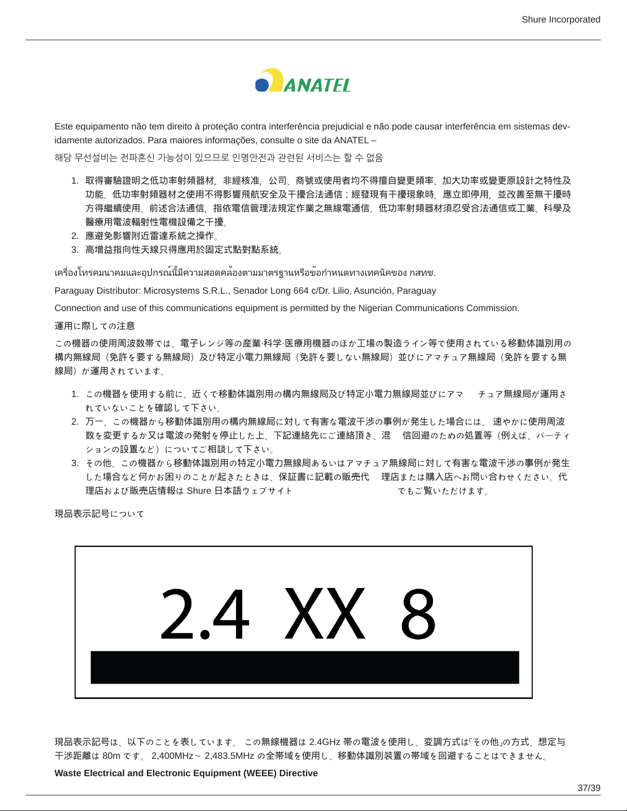
現品表示記号について
現品表示記号は、以下のことを表しています。 この無線機器は 2.4GHz 帯の電波を使用し、変調方式は「その他」の方式、想定与
干渉距離は 80m です。 2,400MHz~ 2,483.5MHz の全帯域を使用し、移動体識別装置の帯域を回避することはできません。
Waste Electrical and Electronic Equipment (WEEE) Directive
Shure Incorporated
38/39
In the European Union and the United Kingdom, this label indicates that this product should not be disposed of with household
waste. It should be deposited at an appropriate facility to enable recovery and recycling.
Registration, Evaluation, Authorization of Chemicals (REACH) Directive
REACH (Registration, Evaluation, Authorization of Chemicals) is the European Union (EU) and the United Kingdom (UK)
chemical substances regulatory framework. Information on substances of very high concern contained in Shure products in a
concentration above 0.1% weight over weight (w/w) is available upon request.
CE Notice:
Hereby, Shure Incorporated declares that this product with CE Marking has been determined to be in compliance with Euro
pean Union requirements. The full text of the EU declaration of conformity is available at the following site: https://
www.shure.com/en-EU/support/declarations-of-conformity.
Authorized European Importer / Representative:
Shure Europe GmbH
Department: Global Compliance
Jakob-Dieffenbacher-Str. 12
75031 Eppingen, Germany
Phone: +49-7262-92 49 0
Fax: +49-7262-92 49 11 4
Email: [email protected]
UKCA Notice:
Hereby, Shure Incorporated declares that this product with UKCA Marking has been determined to be in compliance with UK
CA requirements. The full text of the UK declaration of conformity is available at the following site: https://www.shure.com/en-
GB/support/declarations-of-conformity.
Authorized UK Importer / Representative:
Shure UK Limited
Unit 2, The IO Centre, Lea Road,
Waltham Abbey, Essex, EN9 1 AS, UK
(一)本产品符合“微功率短距离无线电发射设备目录和技术要求”的具体条款和使用场景;
(二)不得擅自改变使用场景或使用条件、扩大发射频率范围、加大发射功率(包括额外加装射频功率放大器),不得擅自更改
发射天线;
(三)不得对其他合法的无线电台(站)产生有害干扰,也不得提出免受有害干扰保护;
(四)应当承受辐射射频能量的工业、科学及医疗(ISM)应用设备的干扰或其他合法的无线电台(站)干扰;
(五)如对其他合法的无线电台(站)产生有害干扰时,应立即停止使用,并采取措施消除干扰后方可继续使用;
(六)在航空器内和依据法律法规、国家有关规定、标准划设的射电天文台、气象雷达站、卫星地球站(含测控、测距、接收、
导航站)等军民用无线电台(站)、机场等的电磁环境保护区域内使用微功率设备,应当遵守电磁环境保护及相关行业主管部门
的规定。
Shure Incorporated
39/39