Loading ...
Loading ...
Loading ...

25
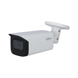
Device components Figure 9-6
Table 9-3 Device components
No. Name No. Name
1 Lens 5 Mounting bracket
2 Front panel 6 Self-tapping screw
3 Fixing screw 7 Expansion bolt
4 Bracket adjusting screw 8 Mounting surface
Fix the mounting bracket ⑤ on the mounting surface ⑧. Step 1
1) Mark the bracket mounting hole positions on the mounting surface ⑧, drill four holes
on the marked positions, insert four expansion bolts ⑦ into the mounting holes and
then tighten.
2) Align the four screw holes on the bottom of the mounting bracket ⑤ with the
expansion bolts, insert four self-tapping screws ⑥ and then tighten.
Fix the device on the mounting bracket ⑤. Step 2
Align the mounting hole positions on the bottom of device casing with the mounting holes
positions on the mounting bracket ⑤, and then install the device on the mounting bracket
with fixing screw ③.
Adjust camera monitoring angle. Step 3
Use a wrench to loosen the adjusting screw ④, adjust camera to the location which needs
to be monitored, and then use wrench to tighten bracket adjusting screw ④ to fix the
device.
Connect the cable to the back panel of the device. Step 4
After device installation and cable connection, you can view monitoring image through
storage device such as XVR.
Loading ...
Loading ...
Loading ...