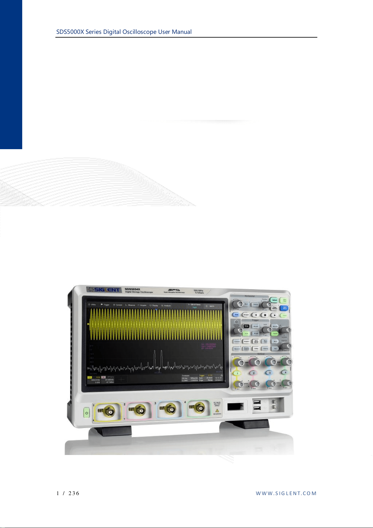
SDS5000X Series Digital Oscilloscope User Manual
1 / 236 W W W . S I G L E N T . C O M
SDS5000X Series
Digital Oscilloscope
User Manual
UM0105X-E01A

SDS5000X Series Digital Oscilloscope User Manual
2 / 236 W W W . S I G L E N T . C O M
Contents
CONTENTS ............................................................................................................................................................................ 2
1 INTRODUCTION ................................................................................................................................................... 6
2 GENERAL SAFETY SUMMARY ....................................................................................................................... 7
2.1 SAFETY TERMS AND SYMBOLS ........................................................................................................................... 7
2.2 WORKING ENVIRONMENT................................................................................................................................... 8
2.3 COOLING REQUIREMENTS................................................................................................................................... 9
2.4 AC POWER ........................................................................................................................................................ 10
2.5 POWER AND GROUND CONNECTIONS ................................................................................................................ 11
2.6 CALIBRATION .................................................................................................................................................... 12
2.7 CLEANING ......................................................................................................................................................... 12
2.8 ABNORMAL CONDITIONS .................................................................................................................................. 12
3 FIRST STEPS......................................................................................................................................................... 14
3.1 DELIVERY CHECKLIST ...................................................................................................................................... 14
3.2 QUALITY ASSURANCE ...................................................................................................................................... 14
3.3 MAINTENANCE AGREEMENT ............................................................................................................................ 15
4 DOCUMENT CONVENTIONS .......................................................................................................................... 16
5 GETTING STARTED .......................................................................................................................................... 17
5.1 POWER ON ......................................................................................................................................................... 17
5.2 SHUT DOWN ...................................................................................................................................................... 17
5.3 SYSTEM STATUS ............................................................................................................................................... 18
5.4 INSTALL OPTIONS ............................................................................................................................................. 18
6 PROBE .................................................................................................................................................................... 19
7 QUICK START...................................................................................................................................................... 21
7.1 FRONT PANEL OVERVIEW................................................................................................................................. 21
7.2 REAR PANEL OVERVIEW .................................................................................................................................. 22
7.3 CONNECTING TO EXTERNAL DEVICES/SYSTEMS.............................................................................................. 24
7.3.1 Power Supply........................................................................................................................................... 24
7.3.2 LAN .......................................................................................................................................................... 24
7.3.3 USB Peripherals...................................................................................................................................... 24
7.3.4 External Monitor ..................................................................................................................................... 24
7.3.5 Auxiliary Output ...................................................................................................................................... 25
7.3.6 SAG1021 Waveform Generator ............................................................................................................. 25
7.3.7 Probes ...................................................................................................................................................... 25
7.3.8 Logic Probe ............................................................................................................................................. 26
8 TOUCH SCREEN DISPLAY .............................................................................................................................. 27
8.1 OVERVIEW ........................................................................................................................................................ 27
8.2 MENU BAR ........................................................................................................................................................ 28
8.3 GRID AREA ....................................................................................................................................................... 29
8.4 CHANNEL DESCRIPTOR BOX............................................................................................................................. 30
8.5 TIMEBASE AND TRIGGER DESCRIPTOR BOXES ................................................................................................. 32
8.6 DIALOG BOX ..................................................................................................................................................... 35
8.7 TOUCH GESTURES............................................................................................................................................. 37
8.8 MOUSE AND KEYBOARD OPERATION ............................................................................................................... 39
8.9 CHOOSING THE LANGUAGE .............................................................................................................................. 39
9 FRONT PANEL ..................................................................................................................................................... 40
9.1 OVERVIEW ........................................................................................................................................................ 40
9.2 VERTICAL CONTROL ......................................................................................................................................... 41
9.3 HORIZONTAL CONTROL .................................................................................................................................... 42
9.4 TRIGGER CONTROL ........................................................................................................................................... 43
9.5 RUN/STOP BUTTON .......................................................................................................................................... 43
9.6 AUTOSETUP BUTTON ....................................................................................................................................... 44
9.7 DECODE/DIGITAL/MATH/REF CONTROL.......................................................................................................... 44
9.8 NAVIGATE CONTROL ........................................................................................................................................ 45
9.9 CURSORS CONTROL .......................................................................................................................................... 46

SDS5000X Series Digital Oscilloscope User Manual
3 / 236 W W W . S I G L E N T . C O M
9.10 UNIVERSAL KNOB............................................................................................................................................. 46
9.11 OTHER BUTTONS .............................................................................................................................................. 47
10 MULTIPLE APPROACHES TO RECALL FUNCTIONS ....................................................................... 48
10.1 MENU BAR ........................................................................................................................................................ 48
10.2 DESCRIPTOR BOX.............................................................................................................................................. 49
10.3 SHORTCUT BUTTON ON THE FRONT PANEL ...................................................................................................... 49
11 QUICKLY CAPTURE THE SIGNAL .......................................................................................................... 50
12 VERTICAL SETUP .......................................................................................................................................... 51
12.1 TURN ON/OFF A CHANNEL ................................................................................................................................ 51
12.2 CHANNEL SETUP ............................................................................................................................................... 51
13 DIGITAL CHANNELS .................................................................................................................................... 57
13.1 OVERVIEW ........................................................................................................................................................ 57
13.2 ENABLE/DISABLE THE DIGITAL CHANNELS ..................................................................................................... 59
13.3 DIGITAL CHANNEL SETUP ................................................................................................................................ 60
14 HORIZONTAL AND ACQUISITION SETUP............................................................................................ 64
14.1 TIMEBASE SETUP .............................................................................................................................................. 64
14.2 ACQUISITION SETUP ......................................................................................................................................... 65
14.2.1 Overview .................................................................................................................................................. 65
14.2.2 Acquisition ............................................................................................................................................... 67
14.2.3 Roll Mode ................................................................................................................................................ 71
14.2.4 Sequence .................................................................................................................................................. 71
14.3 HISTORY............................................................................................................................................................ 75
14.4 ZOOM ................................................................................................................................................................ 78
15 TRIGGER ........................................................................................................................................................... 80
15.1 OVERVIEW ........................................................................................................................................................ 80
15.2 TRIGGER SETUP ................................................................................................................................................ 81
15.3 TRIGGER LEVEL ................................................................................................................................................ 83
15.4 TRIGGER MODE ................................................................................................................................................ 84
15.5 TRIGGER TYPE .................................................................................................................................................. 85
15.5.1 Overview .................................................................................................................................................. 85
15.5.2 Edge Trigger............................................................................................................................................ 86
15.5.3 Slope Trigger ........................................................................................................................................... 86
15.5.4 Pulse Trigger ........................................................................................................................................... 89
15.5.5 Video Trigger .......................................................................................................................................... 90
15.5.6 Window Trigger ...................................................................................................................................... 95
15.5.7 Interval Trigger ....................................................................................................................................... 97
15.5.8 Dropout Trigger ...................................................................................................................................... 97
15.5.9 Runt Trigger ............................................................................................................................................ 99
15.5.10 Pattern Trigger...................................................................................................................................... 100
15.5.11 Qualified Trigger .................................................................................................................................. 101
15.6 TRIGGER SOURCE............................................................................................................................................ 103
15.7 HOLDOFF......................................................................................................................................................... 104
15.8 TRIGGER COUPLING ........................................................................................................................................ 106
15.9 NOISE REJECT ................................................................................................................................................. 106
16 SERIAL TRIGGER AND DECODE ........................................................................................................... 108
16.1 OVERVIEW ...................................................................................................................................................... 108
16.2 I2C TRIGGER AND SERIAL DECODE ............................................................................................................... 110
16.2.1 I2C Signal Settings ................................................................................................................................ 110
16.2.2 I2C Trigger ............................................................................................................................................ 111
16.2.3 I2C Serial Decode ................................................................................................................................. 116
16.3 SPI TRIGGER AND SERIAL DECODE ................................................................................................................ 119
16.3.1 SPI Signal Settings ................................................................................................................................ 119
16.3.2 SPI Trigger ............................................................................................................................................ 121
16.3.3 SPI Serial Decode ................................................................................................................................. 121
16.4 UART TRIGGER AND SERIAL DECODE .......................................................................................................... 122
16.4.1 UART Signal Settings............................................................................................................................ 122
16.4.2 UART Trigger ........................................................................................................................................ 123
16.4.3 UART Serial Decode ............................................................................................................................. 124
16.5 CAN TRIGGER AND SERIAL DECODE ............................................................................................................. 125

SDS5000X Series Digital Oscilloscope User Manual
4 / 236 W W W . S I G L E N T . C O M
16.5.1 CAN Signal Settings .............................................................................................................................. 125
16.5.2 CAN Trigger .......................................................................................................................................... 126
16.5.3 CAN Serial Decode ............................................................................................................................... 126
16.6 LIN TRIGGER AND SERIAL DECODE ............................................................................................................... 128
16.6.1 LIN Signal Settings................................................................................................................................ 128
16.6.2 LIN Trigger............................................................................................................................................ 129
16.6.3 LIN Serial Decode ................................................................................................................................. 129
17 CURSORS......................................................................................................................................................... 131
17.1 OVERVIEW ...................................................................................................................................................... 131
17.2 SELECT AND MOVE CURSORS......................................................................................................................... 136
18 MEASUREMENT ........................................................................................................................................... 139
18.1 OVERVIEW ...................................................................................................................................................... 139
18.2 SET PARAMETERS ........................................................................................................................................... 141
18.3 TYPE OF MEASUREMENT ................................................................................................................................ 144
18.3.1 Vertical Measurement ........................................................................................................................... 144
18.3.2 Horizontal Measurement ...................................................................................................................... 146
18.3.3 Delay Measurement .............................................................................................................................. 147
18.4 MEASUREMENT STATISTICS ........................................................................................................................... 149
18.5 ALL MEASUREMENT ....................................................................................................................................... 150
18.6 GATE ............................................................................................................................................................... 150
19 MATH ............................................................................................................................................................... 152
19.1 OVERVIEW ...................................................................................................................................................... 152
19.2 ADDITION/SUBTRACTION/MULTIPLICATION/DIVISION .................................................................................. 154
19.3 DIFFERENTIAL ................................................................................................................................................. 154
19.4 INTEGRAL ........................................................................................................................................................ 156
19.5 SQUARE ROOT................................................................................................................................................. 158
19.6 FFT ................................................................................................................................................................. 159
20 REFERENCE ................................................................................................................................................... 166
21 SEARCH ........................................................................................................................................................... 168
22 NAVIGATE ...................................................................................................................................................... 171
23 PASS/FAIL ....................................................................................................................................................... 178
23.1 OVERVIEW ...................................................................................................................................................... 178
23.2 MASK SETUP ................................................................................................................................................... 180
23.2.1 Create Mask........................................................................................................................................... 181
23.2.2 Mask Editor ........................................................................................................................................... 182
23.3 PASS/FAIL RULE ............................................................................................................................................. 184
23.4 OPERATION ..................................................................................................................................................... 185
24 DISPLAY .......................................................................................................................................................... 186
25 ARBITRARY WAVEFORM GENERATOR............................................................................................. 193
25.1 OVERVIEW ...................................................................................................................................................... 193
25.2 OUTPUT ........................................................................................................................................................... 195
25.3 WAVE TYPE .................................................................................................................................................... 195
25.4 OTHER SETTING .............................................................................................................................................. 197
25.5 SYSTEM ........................................................................................................................................................... 199
26 SAVE/RECALL ............................................................................................................................................... 201
26.1 SAVE TYPE ...................................................................................................................................................... 201
26.2 INTERNAL SAVE AND RECALL ........................................................................................................................ 204
26.3 EXTERNAL SAVE AND RECALL ....................................................................................................................... 206
26.3.1
File manager ......................................................................................................................................... 206
26.3.2 External Save and Recall Instance....................................................................................................... 208
27 SYSTEM SETTING ........................................................................................................................................ 212
27.1 SYSTEM STATUS ............................................................................................................................................. 212
27.2 SOUND............................................................................................................................................................. 212
27.3 UPGRADE SOFTWARE ..................................................................................................................................... 213
27.4 LANGUAGE ...................................................................................................................................................... 215
27.5 SCREEN SAVER ............................................................................................................................................... 215

SDS5000X Series Digital Oscilloscope User Manual
5 / 236 W W W . S I G L E N T . C O M
27.6 I/O SETTING .................................................................................................................................................... 216
27.6.1 LAN ........................................................................................................................................................ 216
27.6.2 Clock Source.......................................................................................................................................... 217
27.7 DATE/TIME ..................................................................................................................................................... 217
27.8 INSTALL OPTIONS ........................................................................................................................................... 218
27.9 REFERENCE POSITION SETTING ...................................................................................................................... 220
27.10 PERFORM SELF TEST .................................................................................................................................. 223
27.11 DO SELF CAL .............................................................................................................................................. 226
27.12 POWER ON LINE .......................................................................................................................................... 227
27.13 DEBUG ........................................................................................................................................................ 227
28 REMOTE CONTROL .................................................................................................................................... 228
28.1 WEB BROWER ................................................................................................................................................. 228
28.2 OTHER CONNECTIVITY ................................................................................................................................... 230
29 TROUBLESHOOTING ................................................................................................................................. 231
30 CONTACT SIGLENT .................................................................................................................................... 234

SDS5000X Series Digital Oscilloscope User Manual
6 / 236 W W W . S I G L E N T . C O M
1 Introduction
This user manual includes important safety and installation information related
to the SDS5000X series oscilloscopes and includes simple tutorials for basic
operation of the oscilloscope.
SDS5000X Series Digital Oscilloscope User Manual
7 / 236 W W W . S I G L E N T . C O M
2 General Safety Summary
This chapter contains information and warnings that must be followed to keep
the instrument operating under the appropriate safety conditions. In addition to
the safety precautions specified in this section, you must also follow
recognized safety procedures.
2.1 Safety Terms and Symbols
When the following symbols or terms appear on the front or rear panel of the
instrument or in this manual, they indicate special care in terms of safety.
This symbol is used where caution is required. Refer to the
accompanying information or documents in order to protect against
personal injury or damage to the instrument.
This symbol warns of a potential risk of shock hazard.
This symbol is used to denote the measurement ground connection.
This symbol is used to denote a safety ground connection.
This symbol shows that the switch is an On/Standby switch. When it
is pressed, the scope’s state switches between Operation and
Standby. This switch does not disconnect the device's power supply.
To completely power off the scope, the power cord must be
unplugged from the AC socket after the oscilloscope is in the
standby state.
This symbol is used to represent alternating current, or "AC".
CAUTION
The "CAUTION" symbol indicates a potential hazard. It calls
attention to a procedure, practice or condition which may be
dangerous if not followed. Do not proceed until its conditions are fully
understood and met.
WARNING
The "WARNING" symbol indicates a potential hazard. It calls
attention to a procedure, practice or condition which, if not followed,
could possibly cause bodily injury or death. If a WARNING is
indicated, do not proceed until the safety conditions are fully
understood and met.
SDS5000X Series Digital Oscilloscope User Manual
8 / 236 W W W . S I G L E N T . C O M
2.2 Working Environment
This instrument is intended for indoor use and should be operated in a clean,
dry environment with an ambient temperature range of 0 °C - 50 °C.
Note: Direct sunlight, radiators, and other heat sources should be taken into
account when assessing the ambient temperature.
WARNING: Do not operate the oscilloscope in an explosive
atmosphere or wet and damp conditions.
The design of the instrument has been verified to conform to EN 61010-1
safety standard per the following limits:
Installation (overvoltage) Category: II (Mains Supply Connector) & I
(Measuring Terminals)
Degree of Pollution: II
Degree of Protection: I
Note:
Installation (Overvoltage) Category II refers to the local distribution level,
which is applicable to equipment connected to the mains supply (AC power
source).
Installation (Overvoltage) Category I refers to signal level, which is applicable
SDS5000X Series Digital Oscilloscope User Manual
9 / 236 W W W . S I G L E N T . C O M
to equipment measuring terminals that are connected to source circuits in
which measures are taken to limit transient voltages to an appropriately low
level.
Degree of Pollution II refers to a working environment which is dry and non-
conductive pollution occurs. Occasional temporary conductivity caused by
condensation is expected.
Degree of Protection I refers to grounded equipment, in which protection
against electric shock is achieved by basic insulation and by means of a
connection to the protective ground conductor in the building wiring.
CAUTION: Protect the display touch screen of the scope from
excessive impact.
CAUTION: Do not exceed the maximum specified front panel terminal
(CH1, CH2, CH3, CH4, EXT) voltage levels. Refer to Specifications for
more details.
CAUTION: Do not connect or disconnect probes or test leads while
they are connected to a voltage source.
2.3 Cooling Requirements
This instrument relies on the forced air cooling with internal fans and
ventilation openings. Care must be taken to avoid restricting the airflow
around the apertures (fan holes) at each side of the scope. To ensure
adequate ventilation it is required to leave a 15 cm (6 inch) minimum gap
SDS5000X Series Digital Oscilloscope User Manual
10 / 2 3 6 W W W. S I G L E N T. C O M
around the sides of the instrument.
CAUTION: Do not block the ventilation holes located on both sides of
the scope.
CAUTION: Do not allow any foreign matter to enter the scope through
the ventilation holes, etc.
2.4 AC Power
The instrument operates with a single-phase, 100 to 240 Vrms (+/-10%) AC
power at 50/60 Hz (+/-5%), or single-phase 100 - 120 Vrms (+/-10%) AC
power at 400 Hz (+/-5%).
No manual voltage selection is required because the instrument automatically
adapts to line voltage.
Depending on the type and number of options and accessories (probes, PC
port plug-in, etc.), the instrument can consume up to 100 W of power.
Note: The instrument automatically adapts to the AC line input within the
following ranges:
Voltage Range:
90 - 264 Vrms
90 - 132 Vrms
Frequency Range:
47 - 63 Hz
380 - 420 Hz
SDS5000X Series Digital Oscilloscope User Manual
11 / 2 3 6 W W W. S I G L E N T . C O M
2.5 Power and ground connections
The instrument includes a grounded cord set containing a molded three-
terminal polarized plug and a standard IEC320 (Type C13) connector for
making line voltage and safety ground connection. The AC inlet ground
terminal is connected directly to the frame of the instrument. For adequate
protection against electrical shock hazard, the power cord plug must be
inserted into a mating AC outlet containing a safety ground contact. Use only
the power cord specified for this instrument and certified for the country of
use.
Warning: Electrical Shock Hazard!
Any interruption of the protective conductor inside or outside of the
scope, or disconnection of the safety ground terminal creates a
hazardous situation.
Intentional interruption is prohibited.
The position of the oscilloscope should allow easy access to the socket. To
make the oscilloscope completely power off, unplug the instrument power
cord from AC socket.
The power cord should be unplugged from the AC outlet if the scope is not to
be used for an extended period of time.
CAUTION: The outer shells of the front panel terminals (CH1, CH2,
CH3, CH4, EXT) are connected to the instrument’s chassis and
therefore to the safety ground.
SDS5000X Series Digital Oscilloscope User Manual
12 / 2 3 6 W W W. S I G L E N T. C O M
2.6 Calibration
The recommended calibration interval is one year. Calibration should be only
performed by qualified personnel.
2.7 Cleaning
Clean only the exterior of the instrument, using a damp, soft cloth. Do not use
chemicals or abrasive elements. Under no circumstances allow moisture to
penetrate the instrument. To avoid electrical shock, unplug the power cord
from the AC outlet before cleaning.
Warning: Electrical Shock Hazard!
No operator serviceable parts inside. Do not remove covers.
Refer servicing to qualified personnel
2.8 Abnormal Conditions
Only operate the instrument for the purposes specified by the manufacturer.
Do not operate the scope if there is any visible sign of damage or has been
subjected to severe transport stresses.
If you suspect the scope’s protection has been impaired, disconnect the
power cord and secure the instrument against any unintended operation.
Proper use of the instrument depends on careful reading of all instruction and
labels.

SDS5000X Series Digital Oscilloscope User Manual
13 / 2 3 6 W W W. S I G L E N T. C O M
Warning: Any use of the scope in a manner not specified by the
manufacturer may impair the instrument’s safety protection. This
instrument should not be directly connected to human subjects or used
for patient monitoring.

SDS5000X Series Digital Oscilloscope User Manual
14 / 2 3 6 W W W. S I G L E N T. C O M
3 First steps
3.1 Delivery Checklist
First, verify that all items listed on the packing list have been delivered. If you
note any omissions or damage, please contact your nearest SIGLENT
customer service center or distributor as soon as possible. If you fail to
contact us immediately in case of omission or damage, we will not be
responsible for replacement.
3.2 Quality Assurance
The oscilloscope has a 3-year warranty (1-year warranty for probe
attachments) from the date of shipment, during normal use and operation.
SIGLENT can repair or replace any product that is returned to the authorized
service center during the warranty period. We must first examine the product
to make sure that the defect is caused by the process or material, not by
abuse, negligence, accident, abnormal conditions or operation.
SIGLENT shall not be responsible for any defect, damage, or failure caused by
any of the following:
a) Attempted repairs or installations by personnel other than SIGLENT.
b) Connection to incompatible devices/incorrect connection.
c) For any damage or malfunction caused by the use of non-SIGLENT
supplies. Furthermore, SIGLENT shall not be obligated to service a
product that has been modified. Spare, replacement parts, and
repairs have a 90-day warranty.

SDS5000X Series Digital Oscilloscope User Manual
15 / 2 3 6 W W W. S I G L E N T. C O M
The oscilloscope's firmware has been thoroughly tested and is presumed to
be functional. Nevertheless, it is supplied without warranty of any kind
covering detailed performance. Products not made by SIGLENT are covered
solely by the warranty of the original equipment manufacturer.
3.3 Maintenance Agreement
We provide various services on the basis of maintenance agreements. We
offer extended warranties as well as installation, training, enhancement and
on-site maintenance and other services through specialized supplementary
support agreements. For details, please consult your local SIGLENT customer
service center or distributor.
SDS5000X Series Digital Oscilloscope User Manual
16 / 2 36 W W W. S I G L E N T . C O M
4 Document Conventions
For convenience, text surrounded by a box border is used to represent the
button of the front panel. For example, Print represents the "Print" button on
the front panel. Italicsized text with shading is used to represent the touchable
or clickable menu/button/region on the touch screen. For example, DISPLAY
represents the "DISPLAY" menu on the screen:
For the operations that contain multiple steps, the description is in the form of
"Step 1 > Step 2 > ...". As an example, follow each step in the sequence to
enter the upgrade interface:
Utility>System Setting>Upgrade
Press the Utility button on the front panel as step 1, click the System Setting
option on the screen as step 2, and click the Update option on the screen as
step 3 to enter the upgrade interface.

SDS5000X Series Digital Oscilloscope User Manual
17 / 2 3 6 W W W. S I G L E N T. C O M
5 Getting Started
5.1 Power on
SDS5000X provides two ways for power on, which are:
Power on Line
When the “Power on Line” option is enabled, once the oscilloscope is
connected to the AC power supply through the power cord, the oscilloscope
boots automatically. This is useful in automated or remote applications where
physical access to the instrument is difficult/impossible.
Steps for enabling the "Power on Line" function:
Utility>Power On Line
Power on by Manual
When the "Power on Line" option is disabled, the power button on the front
panel is the only control for the power state of the oscilloscope.
5.2 Shut down
Long press the power button for two seconds to turn off the oscilloscope.
Note:
The Power button does not disconnect the oscilloscope from the AC power

SDS5000X Series Digital Oscilloscope User Manual
18 / 2 3 6 W W W. S I G L E N T. C O M
supply. The only way to fully power down the instrument is to unplug the AC
power cord from the outlet. The power cord should be unplugged from the AC
outlet if the scope is not to be used for an extended period of time.
5.3 System Status
Follow the steps below to examine the software and hardware versions of the
oscilloscope.
Utility>System Setting>System Status
See the section "System Status" for details.
5.4 Install Options
A license is necessary to unlock a software option. See the section "Install
Option" for details.

SDS5000X Series Digital Oscilloscope User Manual
19 / 2 3 6 W W W. S I G L E N T. C O M
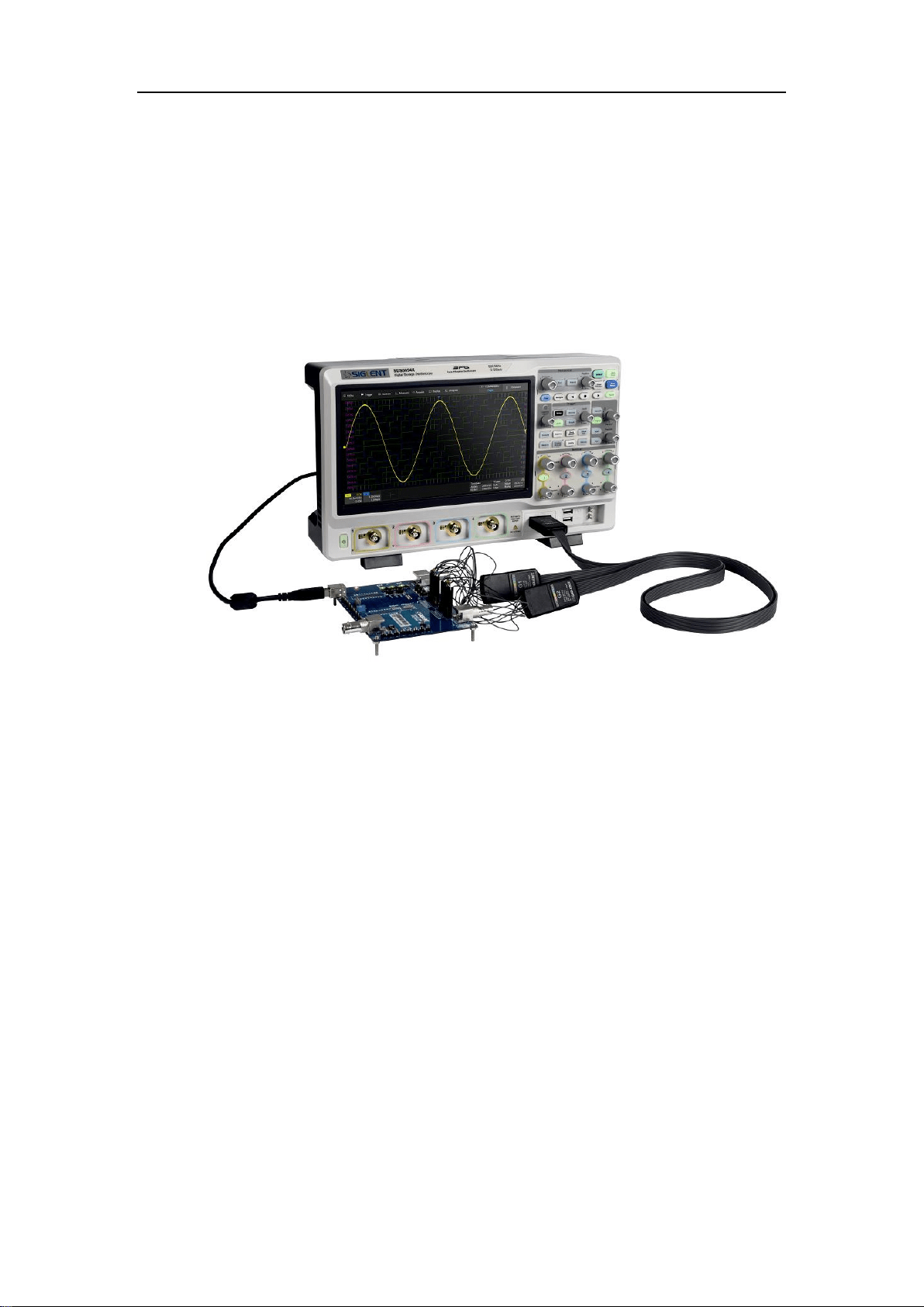
6 Probe
The SDS5000X series oscilloscope package includes passive probes as
standard accessories. Please visit the website at
www.siglent.com for
technical data and ordering information.
Probe Compensation
When a probe is used for the first time, you should compensate it to match the
input channel of the oscilloscope. Non-compensated or poorly compensated
probe may increase measurement inaccuracy or error. The probe
compensation procedures are as follows:
1. Connect the coaxial cable interface (BNC connector) of passive probe
to any channel of the oscilloscope.
2. Connect the probe to the “Compensation Signal Output Terminal”
(Cal) on the front of the oscilloscope. Connect the ground alligator clip
of the probe to the “Ground Terminal” under the compensation signal
output terminal.
3. Press the Auto Setup button.
4. Check the waveform displayed and compare it with the following.

SDS5000X Series Digital Oscilloscope User Manual
20 / 2 3 6 W W W. S I G L E N T. C O M
Under
Compensated
Perfectly
Compensated
Over
Compensated
5. Use a non-metallic driver to adjust the low-frequency compensation
adjustment hole on the probe until the waveform displayed is as the
“Perfectly compensated” in the figure above.
SDS5000X Series Digital Oscilloscope User Manual
21 / 2 3 6 W W W. S I G L E N T. C O M
7 Quick Start
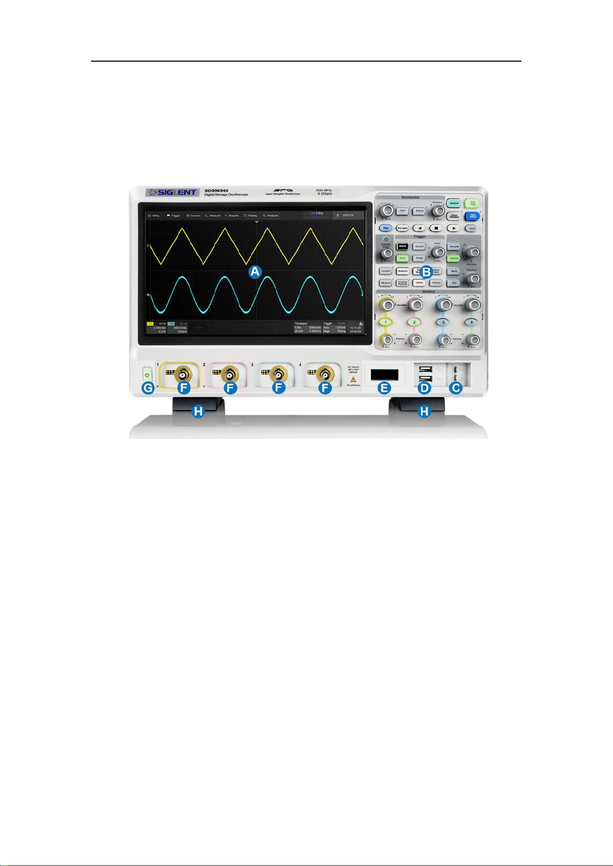
7.1 Front Panel Overview
A. Touch Screen Display: The display and major functions area. See
"Touch Screen Display" chapter for more details.
B. Front Panel: Includes knobs and buttons. See "Front Panel" chapter
for more details.
C. Probe Compensation/ Ground Terminal: Supplies a 0-3 V 1 kHz
square wave for compensating the probes.
D. USB Host Ports: Connect the USB host ports to USB storage
devices for data transfer, or USB mouse / keyboard for control.
E. Digital Input Connector: Receives digital signals from the SPL2016
digital probe.
F. Analog Input Connectors
SDS5000X Series Digital Oscilloscope User Manual
22 / 2 3 6 W W W. S I G L E N T. C O M
G. Power Switch
H. Supporting Legs: Adjust the supporting legs properly to use them as
stands to tilt the oscilloscope for stable positioning of the oscilloscope.
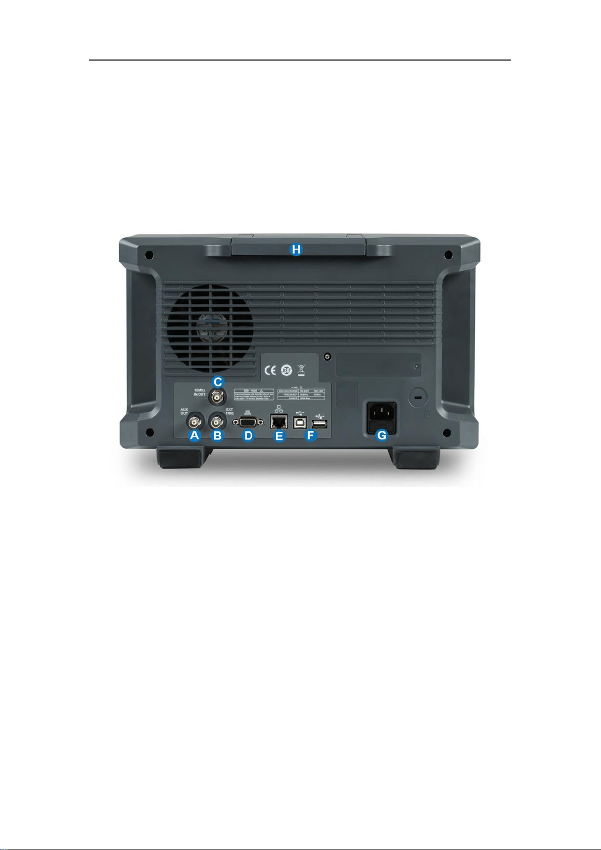
7.2 Rear Panel Overview
A. Auxiliary Out: Outputs the trigger indicator. When Pass / Fail is
enabled, outputs the pass / fail signal.
B. Ext Trigger Input
C. 10 MHz Clock Input/Output: Receives or outputs 10 MHz reference
clock for synchronization between the oscilloscope and other
instruments.
D. VGA Video Output: Connect the port to an external monitor. The
resolution is 1024 * 600.
E. LAN Port: Connect the port to the network for remote control.

SDS5000X Series Digital Oscilloscope User Manual
23 / 2 3 6 W W W. S I G L E N T. C O M
F. USB Ports: One USB device to connect with a PC for remote control
and one USB host to connect with a USB storage device or USB
mouse / keyboard.
G. AC Power Input
H. Handle

SDS5000X Series Digital Oscilloscope User Manual
24 / 2 3 6 W W W. S I G L E N T. C O M
7.3 Connecting to External Devices/Systems
7.3.1 Power Supply
The standard power supply for the instrument is 100~240 V, 50/60 Hz or
100~120 V, 400 Hz. Please use the power cord provided with the instrument
to connect it to AC power.
7.3.2 LAN
Connect the LAN port to the network with a network cable with RJ45 head for
remote control.
Follow the steps below to set LAN connection:
Utility
>
System Setting
>
I/O
>
LAN Config
7.3.3 USB Peripherals
Connect a USB storage device (FAT32 format) to one of the USB host ports
for data transfer, or connect USB mouse / keyboard to one of the USB host
ports for controlling the instrument.
7.3.4 External Monitor
Use a D-Sub cable to connect the VGA port to an external monitor. The video
signal from the VGA port has a 1024 * 600 resolution.

SDS5000X Series Digital Oscilloscope User Manual
25 / 2 3 6 W W W. S I G L E N T. C O M
7.3.5 Auxiliary Output
When Pass / Fail is enabled, the port outputs the pass / fail signal, otherwise it
outputs the trigger indicator.
See the chapter "Pass/Fail " for more details.
7.3.6 SAG1021 Waveform Generator
Activate the SDS-5000X-FG option and connect the SAG1021 USB function /
arbitrary waveform generator module to any USB host pot on the oscillosc ope.
The oscilloscope can now control the USB module to output specified
waveforms.
Press the WaveGen button on the front panel or touch the screen Utility
>
AWG Menu to set the waveform.
7.3.7 Probes
The SDS5000X series oscilloscope supports active probe and passive
probes. The specifications and documents of the probe can be obtained at
www.siglent.com.
SDS5000X Series Digital Oscilloscope User Manual
26 / 2 3 6 W W W. S I G L E N T. C O M
7.3.8 Logic Probe
To connect the logic probe: Insert the probe, with the correct side facing up,
until you hear a “click”.
To remove the logic probe: Depress the buttons on each side of the probe,
then pull out it.
SDS5000X Series Digital Oscilloscope User Manual
27 / 2 3 6 W W W. S I G L E N T. C O M
8 Touch Screen Display
8.1 Overview
The entire SDS5000X display is a capacitive touch screen. Use your fingers to
touch, drag, pinch, spread, or draw a selection box. Many controls that display
information also work as “buttons” to access other functions. If you using any
mouse, you can click anywhere – that you can touch - to activate a control; in
fact, you can alternate between clicking and touching the control, whichever is
convenient.
A. Menu Bar
B. Grid Area
C. Trigger Level Indicator
D. Cursors
E. Channel Descriptor box descriptor boxes

SDS5000X Series Digital Oscilloscope User Manual
28 / 2 3 6 W W W. S I G L E N T. C O M
F. Trigger Delay Indicator
G. Timebase and Trigger descriptor box
H. Dialog Box
Trigger Level Line (Vertical) and Trigger Delay Indicator (Horizontal) show
the trigger position of the waveform.
Cursors show where measurement points have been set. Move the cursors
to quickly reposition the measurement point.
Channel Descriptor boxes include analog channels (C1 ~ C4), digital
channels (D), math (M) and reference (Ref). They are located under the grid
area, showing the parameters of the corresponding traces. Touching the
boxes creates a dialog box.
Timebase and Trigger Descriptor boxes show the parameters of the
timebase and trigger respectively. Touching the boxes creates a dialog box for
the selected item.
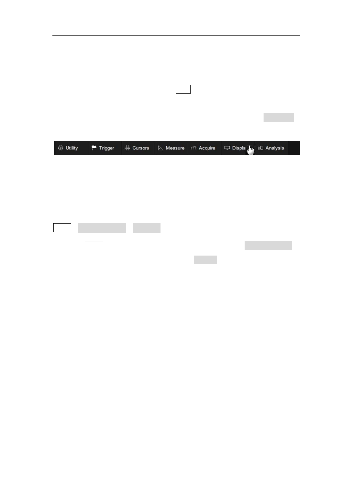
8.2 Menu Bar
Menu bar with drop-down menus lets you access set-up dialogs and other
functions. All functionality can be accessed through the menu bar. It is not
necessary for common operations. You can enter most menus by using the
front panel or parameter description labels instead of the menu bar. However,
the following operations can only be accessed through the menu bar:
SDS5000X Series Digital Oscilloscope User Manual
29 / 2 3 6 W W W. S I G L E N T. C O M
Utility>Help
Acquire>Sequence
Acquire>XY Mode
Analysis>Pass/Fail
8.3 Grid Area
The grid area displays the waveform traces. Traces can be moved by
dragging, and re-scaled by pinch and spread. The area is divided into 8
(vertical) * 10 (horizontal) grids. The best display effect can be obtained by
adjusting the waveform intensity and graticule. Follow the steps below to set
these parameters:
Display
>
Intensity,
Display
>
Graticule
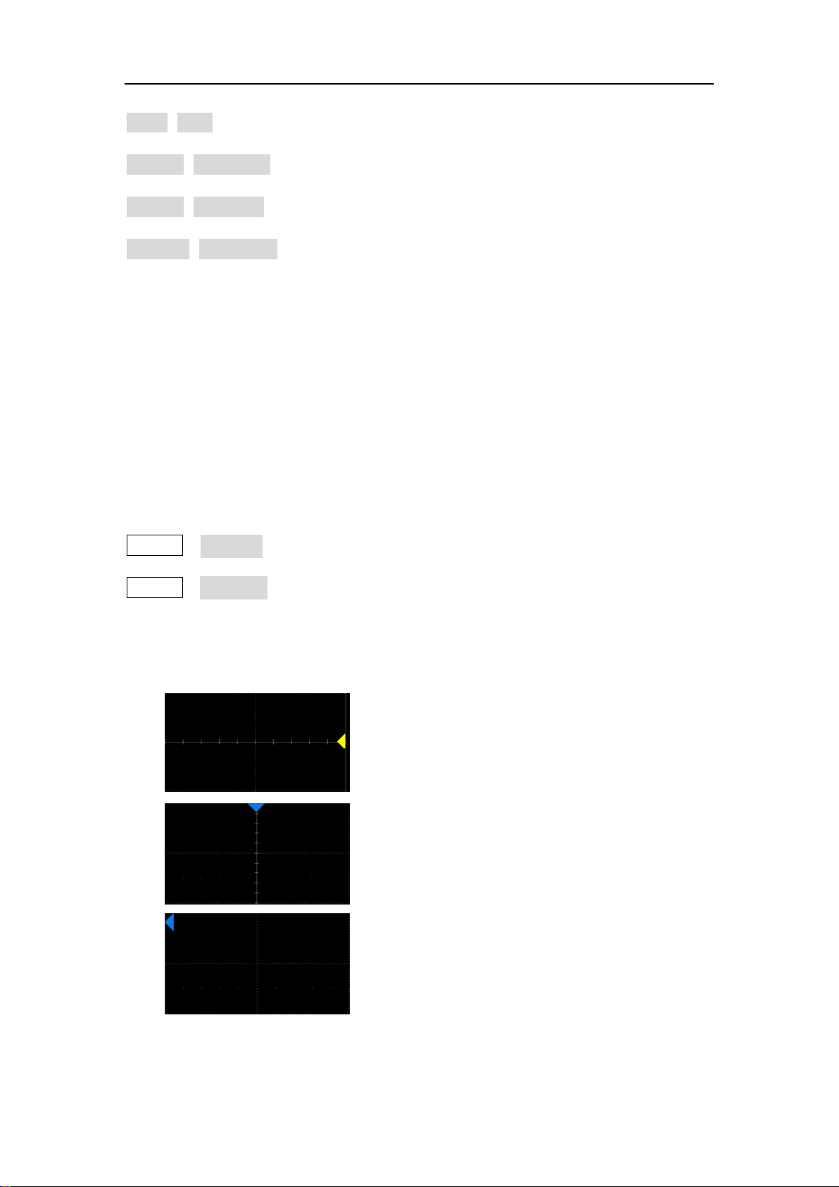
There are multiple indicators on the grid:
Trigger Level Indicator shows the level
where the waveform triggers on the vertical
axis.
Trigger Delay Indicator locates where the
waveform triggers on the horizontal axis...
When the trigger position is outside the
screen, the direction of the triangle changes
to point outside the screen.
SDS5000X Series Digital Oscilloscope User Manual
30 / 2 3 6 W W W. S I G L E N T. C O M
Channel Offset Indicator with a channel
number shows the offset position of the
corresponding channel.
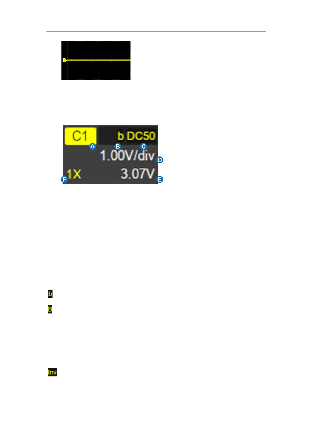
8.4 Channel Descriptor Box
A. Channel Index
B. Bandwidth Limit
indicator
C. Coupling and Input
Impedance
D. Vertical Scale
E. Vertical Offset
F. Probe Attenuation
Factor
Bandwidth Limit Indicators:
The SDS5000X has two available bandwidth limits: 20 and 200 MHz. They are
indicated by the following icons:
:20 MHz bandwidth limit
:200 MHz bandwidth limit
None: Full bandwidth
Invert Indicator -- shows that the current channel is inverted:
: Invert has been turned on
None: Invert has been turned off

SDS5000X Series Digital Oscilloscope User Manual
31 / 2 3 6 W W W. S I G L E N T. C O M
Coupling and Input Impedance:
:DC coupling, 1MΩ impedance
:DC coupling, 50Ω impedance
:AC coupling, 1MΩ impedance
:AC coupling, 50Ω impedance
:Ground
Vertical Scale: The scale of each grid in the vertical direction. For example,
when the vertical scale is 1.00 V/div, the full scale of the oscilloscope is 1.00
V/div * 8 div = 8 V.
Vertical Offset: The offset of the channel in the vertical direction. When the
vertical offset is 0, the channel offset indicator is located in the middle of the
vertical axis.
Probe Attenuation Factor: Set the probe attenuation factor to match the
actual attenuation of the probe. The oscilloscope automatically calculates the
vertical scale according to the probe attenuation factor. For example, the
vertical scale of the oscilloscope is 100 mV/div with 1X attenuation, and 1
V/div if the attenuation factor is changed to 10X. When inserting a standard
10X passive probe with probe sense terminal, the oscilloscope will
automatically set the factor to 10X.
:1:1 attenuation, suitable for direct coaxial cable connection or passive
probes with 1X attenuation
SDS5000X Series Digital Oscilloscope User Manual
32 / 2 3 6 W W W. S I G L E N T. C O M
:10:1 attenuation, suitable for general passive probes or active probes
with 10X attenuation
:100:1 attenuation, suitable for some high-voltage probes
:Custom attenuation factor
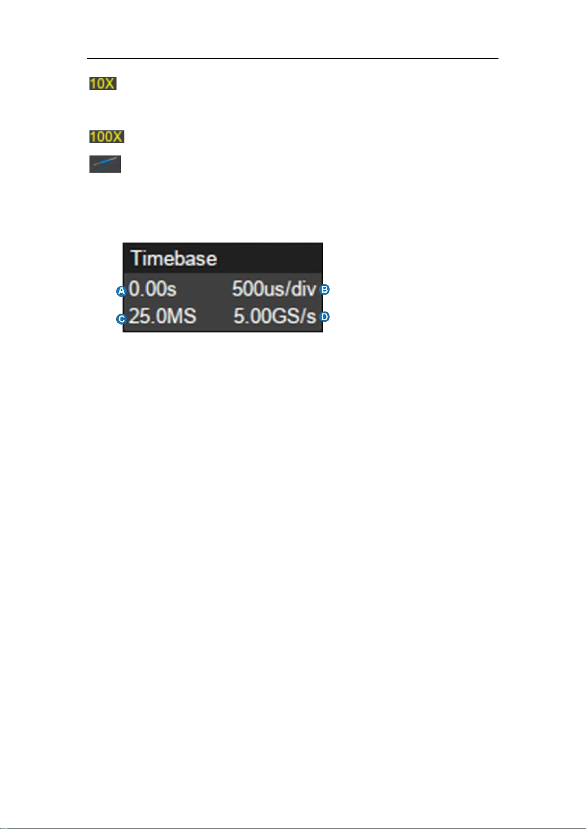
8.5 Timebase and Trigger Descriptor Boxes
A. Trigger delay
B. Horizontal scale
(
timebase
)
C. # Samples
D. Sample Rate
Trigger delay: The time offset of trigger position. When trigger delay is 0, the
trigger delay indicator is in the center of the horizontal axis of the grid area.
Horizontal scale: Timebase, the time of each grid in the horizontal direction.
For example, if the scale is 500 us/div, the time of each grid is 500 us, and the
full screen time range of the oscilloscope is 500 us/div*10 div = 5 ms.
# Samples: The number of sample points on the current screen.
Sample Rate: The current sample rate.
SDS5000X Series Digital Oscilloscope User Manual
33 / 2 3 6 W W W. S I G L E N T. C O M
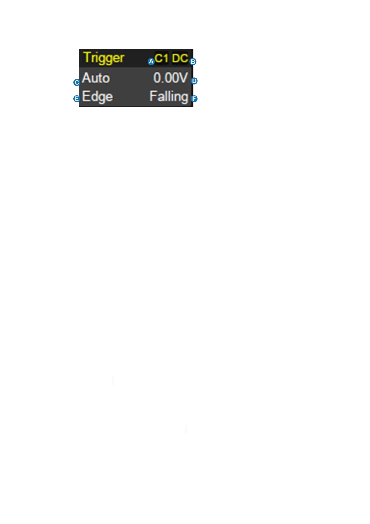
A. Trigger source
B. Trigger coupling
C. Trigger mode
D. Trigger level
E. Trigger type
F. Trigger slope
Trigger source
C1~C4: Analog channels
EXT: External trigger channel
EXT/5: 5x attenuation of external trigger channel
AC Line: AC mains supply
D0~D15: Digital channels
Trigger coupling: Coupling mode of the current trigger source. It is only valid
when the trigger source is C1~C4, EXT or EXT/5.
DC:All the signal’s frequency components are coupled to the trigger
circuit for high frequency bursts or where the use of AC coupling would
shift the effective trigger level.
AC:The signal is capacitively coupled. DC levels are rejected. See the
datasheet for details of the cut-off frequency.
HFR: Signals are DC coupled to the trigger circuit, and a low-pass filter
network attenuates high frequencies (used for triggering on low
frequencies). See the datasheet for details of the cut-off frequency.
LFR:The signal is coupled through a capacitive high-pass filter network,
DC is rejected and low frequencies are attenuated. For stable triggering

SDS5000X Series Digital Oscilloscope User Manual
34 / 2 3 6 W W W. S I G L E N T. C O M
on medium to high frequency signals. See the datasheet for details of
the cut-off frequency.
Trigger mode
Auto: The oscilloscope will sweep without a set trigger. An internal timer
triggers the sweep after a preset timeout period so that the display
refreshes continuously. This is helpful when first analyzing unknown
signals. Otherwise, Auto functions the same as Normal when a trigger
condition is found.
Normal: Sweeps only if the input signal meets the trigger condition.
Otherwise it continues to display the last acquired waveform.
Stop: Stops the acquisition and displays the last acquired waveform.
Trigger level: The source voltage level or levels that mark the threshold for the
trigger to fire. Trigger levels specified in Volts normally remain unchanged when
the vertical gain or offset is modified.
Trigger type: See the chapter "Trigger" for details.
SDS5000X Series Digital Oscilloscope User Manual
35 / 2 3 6 W W W. S I G L E N T. C O M
8.6 Dialog Box
Dialog box on the right side of the screen is the main area for setting the
parameters of the selected function.
A. Title bar. Touching the
bar can hide the dialog
box, and touching again
can open the dialog box.
B. Parameter setting area.
C. Scroll bar. When
parameters are more
than the displayed range,
the blue scroll bar will be
displayed. By sliding the
dialog area up and down,
or rolling the mouse
wheel, it can scroll to the
area not displayed.
To Set Parameters
The SDS5000X provides a couple of different ways to input/select parameters:
Switch: Sets parameters with two states, such
as to enable or disable a function. Touch the
switch region to change from one state to the
other.
SDS5000X Series Digital Oscilloscope User Manual
36 / 2 3 6 W W W. S I G L E N T. C O M
List: Sets parameters with
more than two options,
such as coupling mode of
channels. Touch the
parameter region, and
then select the expected
option from the pop-up
list.
Virtual Keypad: Sets parameters with
numerical value. Touch the parameter region,
and the parameter can be adjusted by the
universal knob on the front panel; touch the
region again, then the virtual keypad appears:
Let’s use the operation of setting the “deskew” of a channel as an example: If
the expected value is 65 ns, input “65” on the virtual keypad, and then choose
the unit n to complete the operation. On the virtual keypad, touching the
button Max, Min, and Default quickly sets the parameter to its maximum,
SDS5000X Series Digital Oscilloscope User Manual
37 / 2 3 6 W W W. S I G L E N T. C O M
minimum and default values.
Hide Dialog Box
When the dialog box is opened, the grid area will be compressed horizontally
to display the complete waveform. After setting the parameters, in order to
achieve the best waveform display effect, you can touch the title bar in the
upper right corner to hide the dialog box. Touching it again can open the
dialog box.
Turn on the Dialog box
Turn off the Dialog box
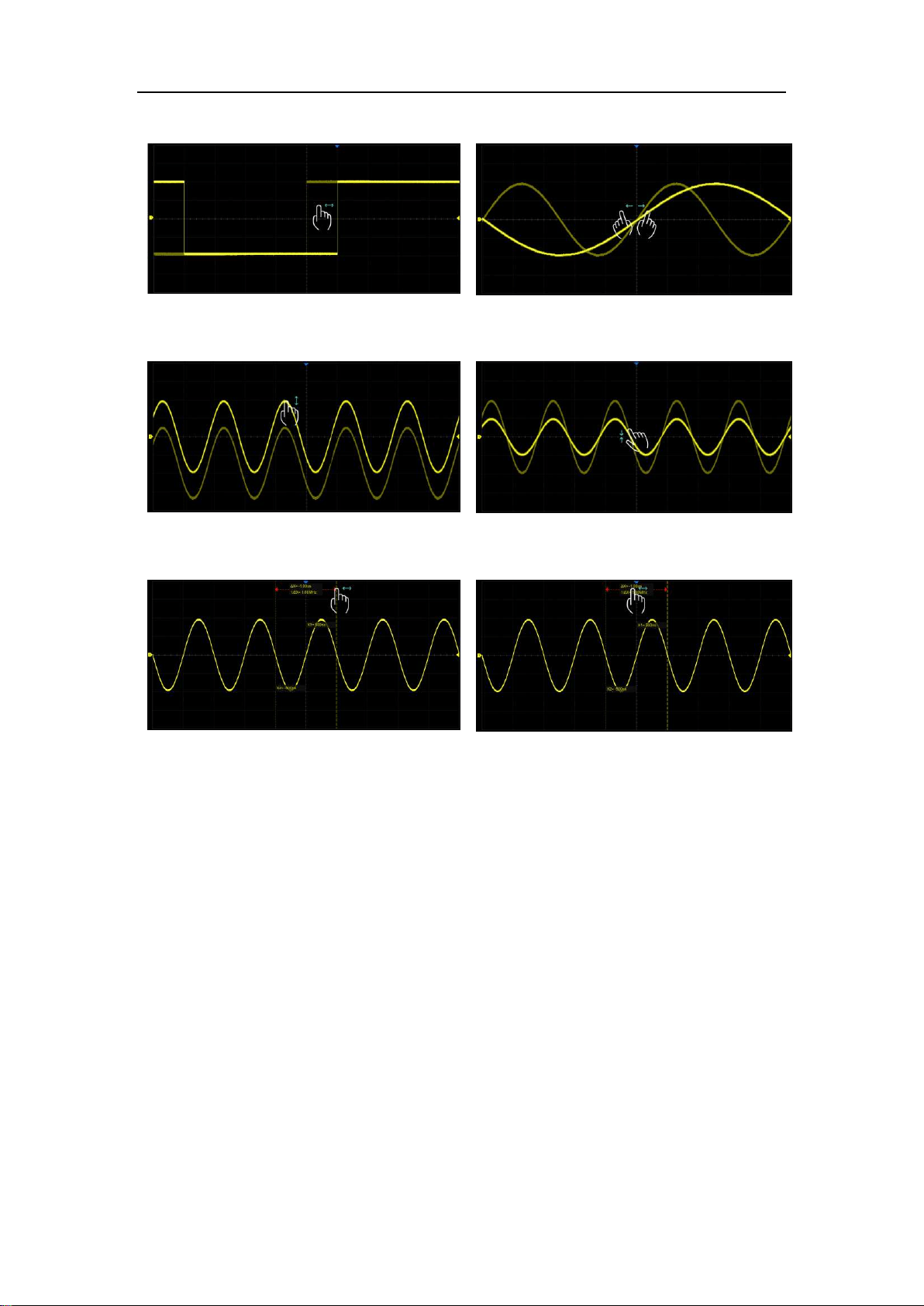
8.7 Touch Gestures
Waveforms, cursors and trigger level can be adjusted by touch gestures in the
grid area.
SDS5000X Series Digital Oscilloscope User Manual
38 / 2 3 6 W W W. S I G L E N T. C O M
Drag the waveform left and right to move it
on the horizontal axis
Pinch and spread the waveform
horizontally to re-scale the timebase
Drag the waveform up and down to move it
on the vertical axis
Pinch and spread the waveform vertically to
re-scale the vertical gain
Touch and drag the cursor to move it
Touch and drag the cursor information
region to move the pair of cursors
simultaneously

SDS5000X Series Digital Oscilloscope User Manual
39 / 2 3 6 W W W. S I G L E N T. C O M
8.8 Mouse and Keyboard Operation
The SDS5000X user interface features mouse control as well as the touch
screen. . If the oscilloscope is connected to a USB mouse, you can click on
the object with the mouse instead of touching the object. Similarly, if a USB
keyboard is connected, you can use the keyboard to input characters instead
of using the virtual keyboard.
8.9 Choosing the Language
Follow Utility
>
System Setting
>
Language to choose the language. See the
section "Language " for details.
SDS5000X Series Digital Oscilloscope User Manual
40 / 2 3 6 W W W. S I G L E N T. C O M
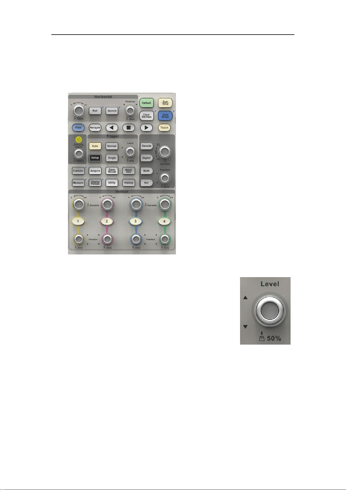
9 Front Panel
9.1 Overview
The front panel is designed to
operate the basic functions
without having to open the
software menu. Most of the
front panel controls duplicate
functionality available through
the touch screen display but
the operation is more quickly
achieved.
All the knobs on the front panel are multi-
function. They can be pushed as well as
rotated. . Pushing a knob quickly recalls a
specific function, which is indicated by the
silkscreen near to the knob.
SDS5000X Series Digital Oscilloscope User Manual
41 / 2 3 6 W W W. S I G L E N T. C O M
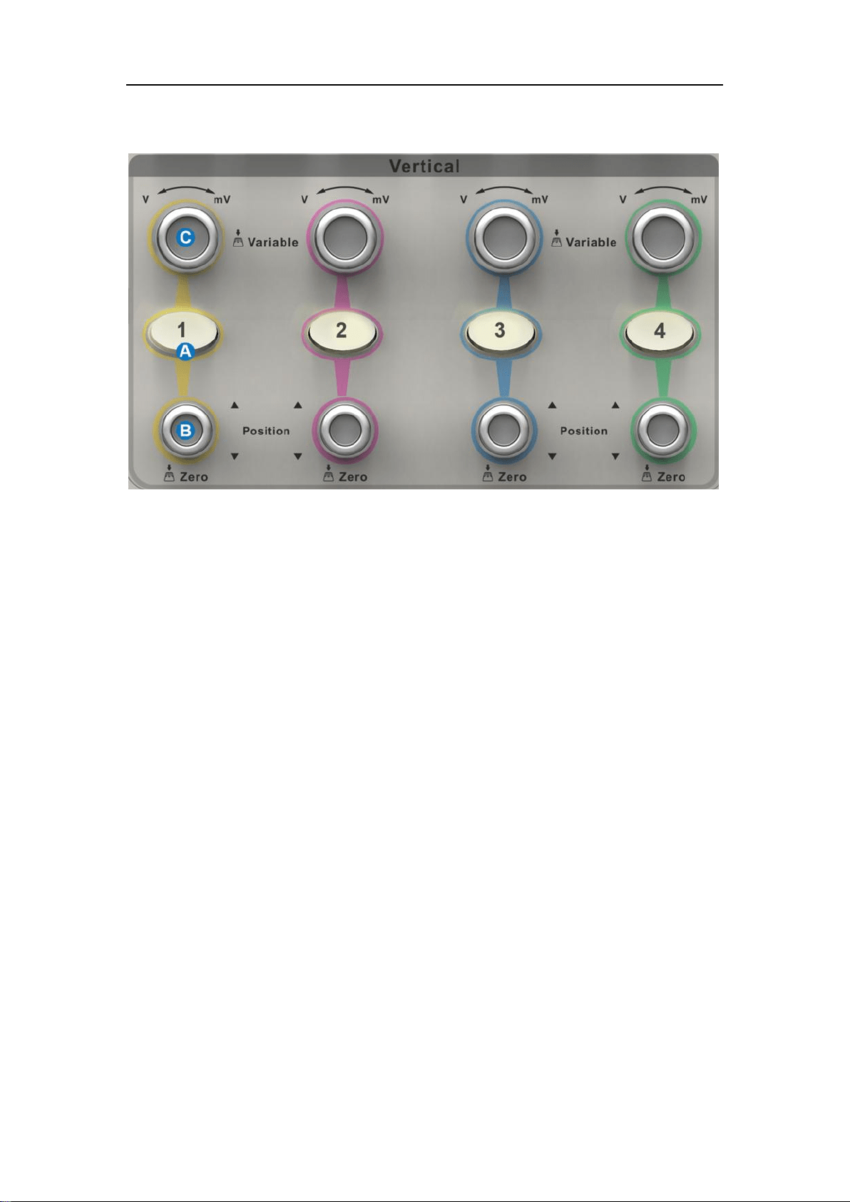
9.2 Vertical Control
A. When a channel is disabled, push channel button to turn it on. When
the channel is turned on and activated, push the button to disable it.
B. Rotate the knob to adjust the DC offset or vertical position of the
channel. Push to set the offset to zero
C. Rotate the knob to adjust vertical scale (volts/div); push to switch to
alternate between coarse and fine adjustments.
SDS5000X Series Digital Oscilloscope User Manual
42 / 2 3 6 W W W. S I G L E N T. C O M
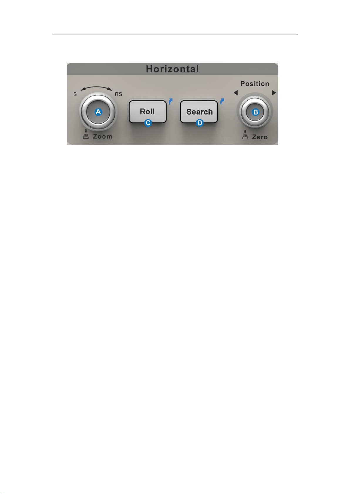
9.3 Horizontal Control
A. Rotate to adjust horizontal scale (time/div); push to enable Zoom;
push again to exit Zoom mode.
B. Rotate to adjust trigger delay; push to set trigger delay to zero.
C. Push to enable horizontal Roll; push again to exit Roll mode. At
timebase settings larger than 50 ms/div, it is recommended to set the
oscilloscope to Roll mode so that the waveform is displayed in real
time.
D. Push to enable Search; push again to close Search.
SDS5000X Series Digital Oscilloscope User Manual
43 / 2 3 6 W W W. S I G L E N T. C O M
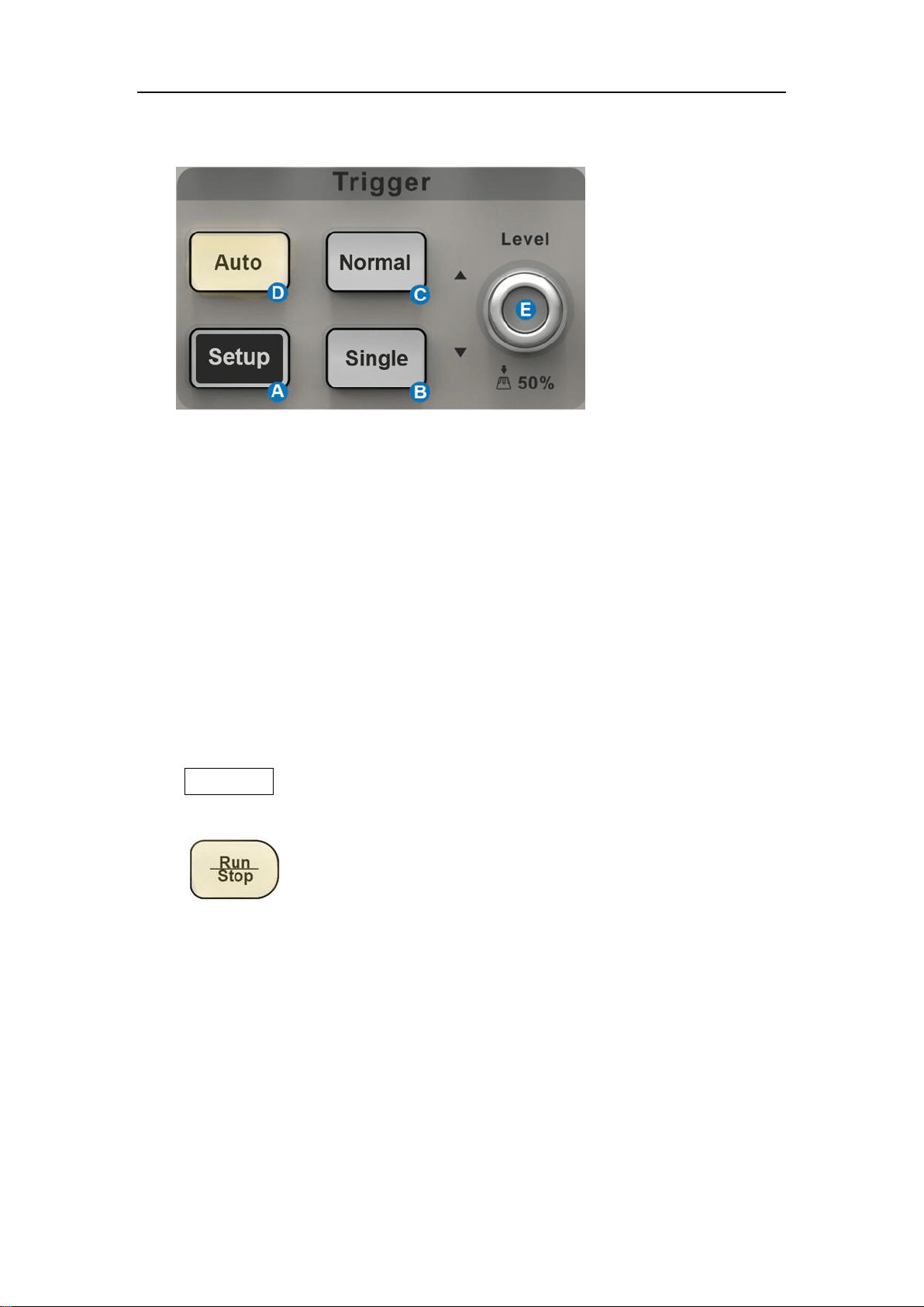
9.4 Trigger Control
A. Opens trigger setup dialog box
B. Single mode: Triggers once when all conditions are met
C. Normal mode: Triggers repeatedly when all conditions are met
D. Auto mode: Triggers after preset period if no valid trigger occurs
E. Trigger level adjustment: Push to set the level to 50% of the
waveform
9.5 Run/Stop Button
Press the button to switch the acquisition state between
Run and Stop. When the state is Run, and the button is
illuminated in yellow; when the state is Stop, the button
is illuminated in red.
SDS5000X Series Digital Oscilloscope User Manual
44 / 2 3 6 W W W. S I G L E N T. C O M
9.6 AutoSetup Button
The oscilloscope will automatically set the vertical
scale, horizontal scale and trigger level according to
the input signal to get optimum waveform display. You
can also perform an AutoSetup operation following the
steps Trigger ->Auto Setup.
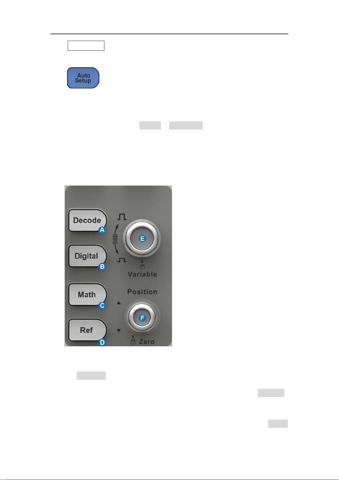
9.7 Decode/Digital/Math/Ref Control
A. Press the button to turn on serial bus decode function and open the
DECODE dialog box. Press again to turn off the decode function.
B. Press the button to turn on the digital channel and open the DIGITAL
dialog box. Press again to turn off the digital channels.
C. Press the button to turn on the math function and open the MATH
SDS5000X Series Digital Oscilloscope User Manual
45 / 2 3 6 W W W. S I G L E N T. C O M
dialog box. Press again to turn off math function.
D. Press the button to turn on the reference function and open
REFERENCE dialog box. Press again to turn off the reference
function.
E. Rotate the knob to adjust the vertical scale (Volt/div) of Math or Ref. It
can also be used to change the selected digital channel.
F. Rotate the knob to adjust the vertical offset of Math or Ref, press
down the knob to quickly reset the vertical offset to zero. It can also
be used to adjust the position of selected digital channel on the
screen.
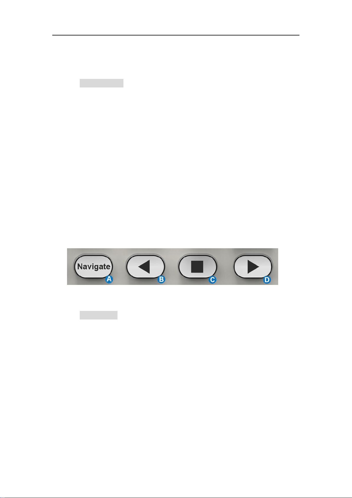
9.8 Navigate Control
A. Press the button to turn on navigate function and open the
NAVIGATE dialog box. Press again to turn off navigate.
B. Play backward
C. Pause
D. Play forward
SDS5000X Series Digital Oscilloscope User Manual
46 / 2 3 6 W W W. S I G L E N T. C O M
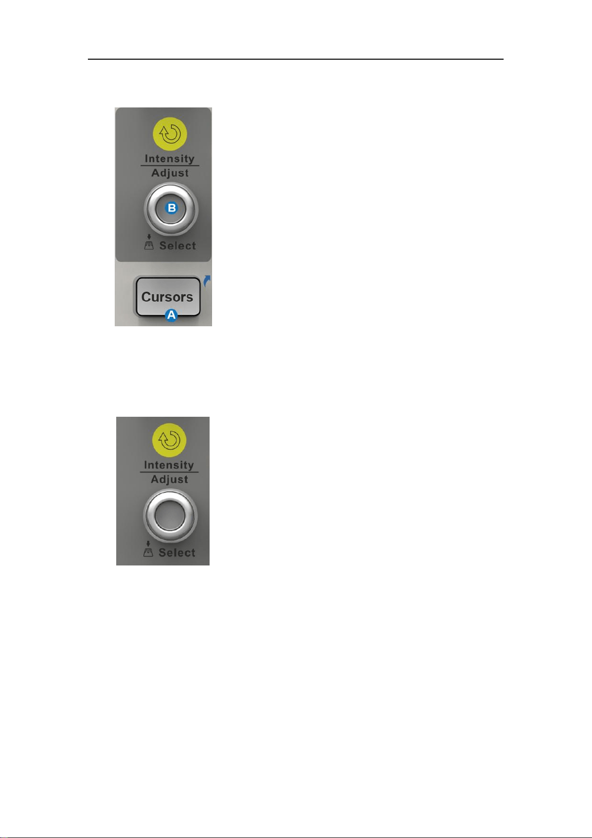
9.9 Cursors Control
A. Push the button to open the cursors setup
dialog box
B. Rotate the knob to move selected cursor;
push to select different cursor
9.10 Universal Knob
When the parameter setting area is highlighted, you
can use the Universal Knob to adjust or set the
parameter. Press the knob to select an option from
the list.
SDS5000X Series Digital Oscilloscope User Manual
47 / 2 3 6 W W W. S I G L E N T. C O M
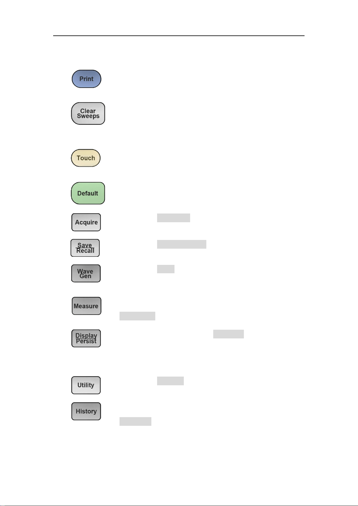
9.11 Other Buttons
Performs a screenshot save to an external storage
device. The supported format includes .bmp\.jpg\.png.
Clears the data or display in multiple sweeps, including
display persistence, measurement statistics, average
sweeps and Pass/Fail statistics.
Enables/Disables the touch screen. The LED on the
button lights to indicate that the touch screen is working.
Resets the oscilloscope to the default configuration.
Recalls the ACQUIRE dialog box.
Recalls the SAVE/RECALL dialog box.
Recalls the AWG dialog box. The LED on the button
lights to indicate the output of the AWG is enabled.
Enables/Disables measurements and recalls the
MEASURE dialog box.
Press the button to recall the DISPLAY dialog box. The
second press turn on Persist, and lights the button.
Press the button again to turn off Persist.
Recalls the UTILITY dialog box.
Enables/Disables measurement and recalls the
HISTORY dialog box.
SDS5000X Series Digital Oscilloscope User Manual
48 / 2 3 6 W W W. S I G L E N T. C O M
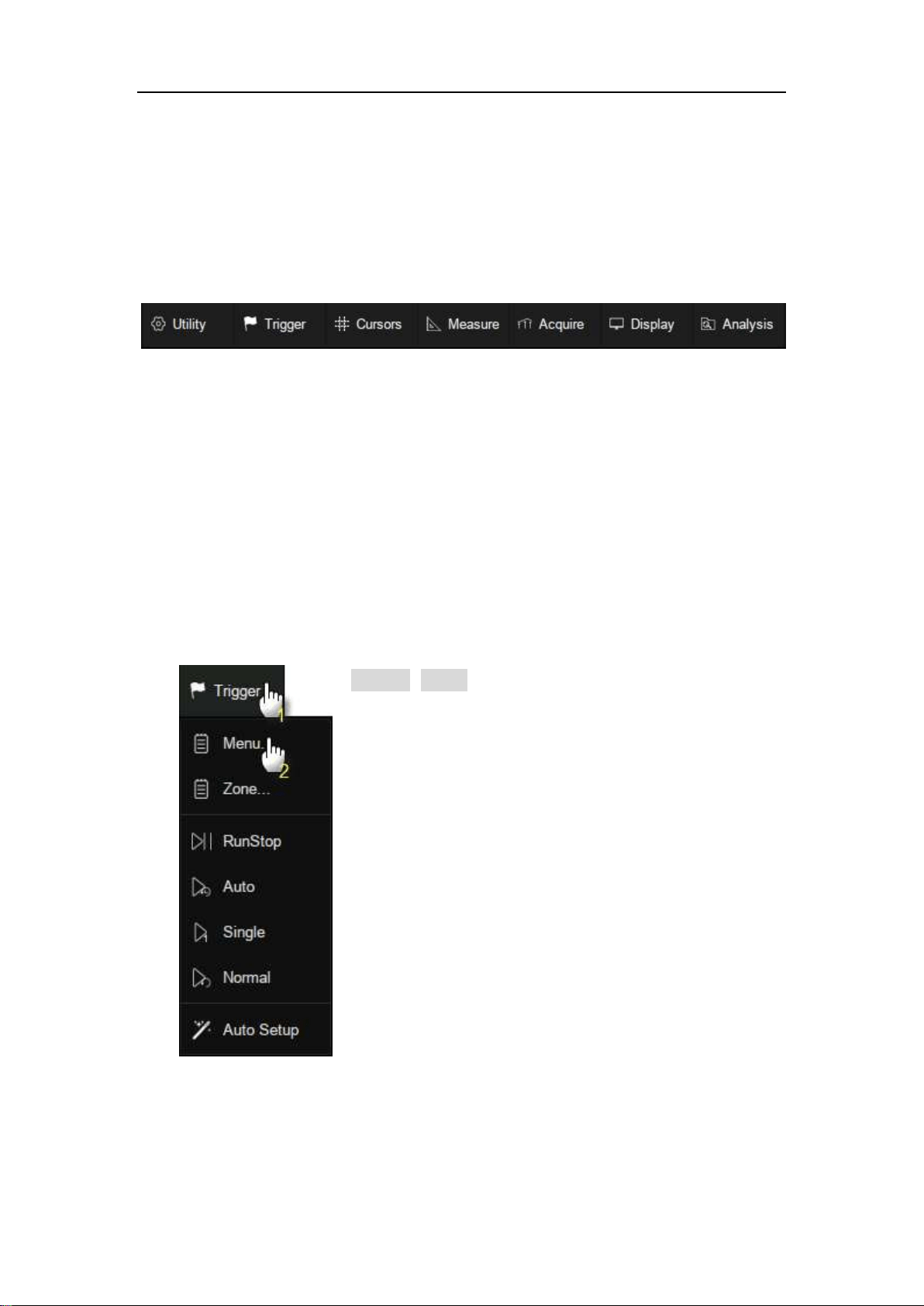
10 Multiple Approaches to Recall Functions
The oscilloscope can recall functions through different approaches.
10.1 Menu Bar
If you are familiar with common current computer programs, you may first
choose to access a function by the drop-down menu from the menu bar at the
top of the display.
For example, to open the trigger setup dialog box, you can follow the steps
below:
Trigger>Menu
The operations can be completed either by touch
or by mouse clicks.
SDS5000X Series Digital Oscilloscope User Manual
49 / 2 3 6 W W W. S I G L E N T. C O M
10.2 Descriptor Box
For setup of channels, math, ref, timebase and trigger, there are dialog boxes
at the bottom of the display. For the introduction of the descriptor box, see
sections "Channel Descriptor Box" and "Timebase and Trigger Descriptor
Box".
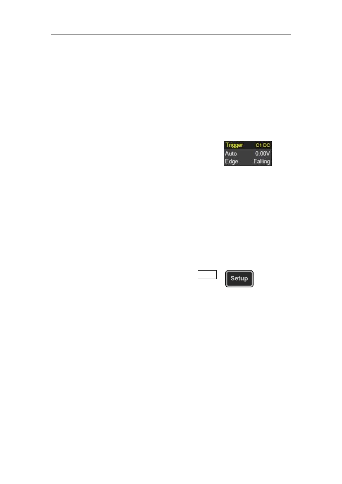
For the example above, touch the trigger descriptor
box and the trigger setup dialog box will be activated.
10.3 Shortcut Button on the Front panel
Most of the functions of the oscilloscope can be recalled directly by the
shortcut buttons on the front panel. See the chapter "Front Panel" for details.
To open the trigger setup dialog box, press the Setup
button in the trigger control area on the front panel.
SDS5000X Series Digital Oscilloscope User Manual
50 / 2 3 6 W W W. S I G L E N T. C O M
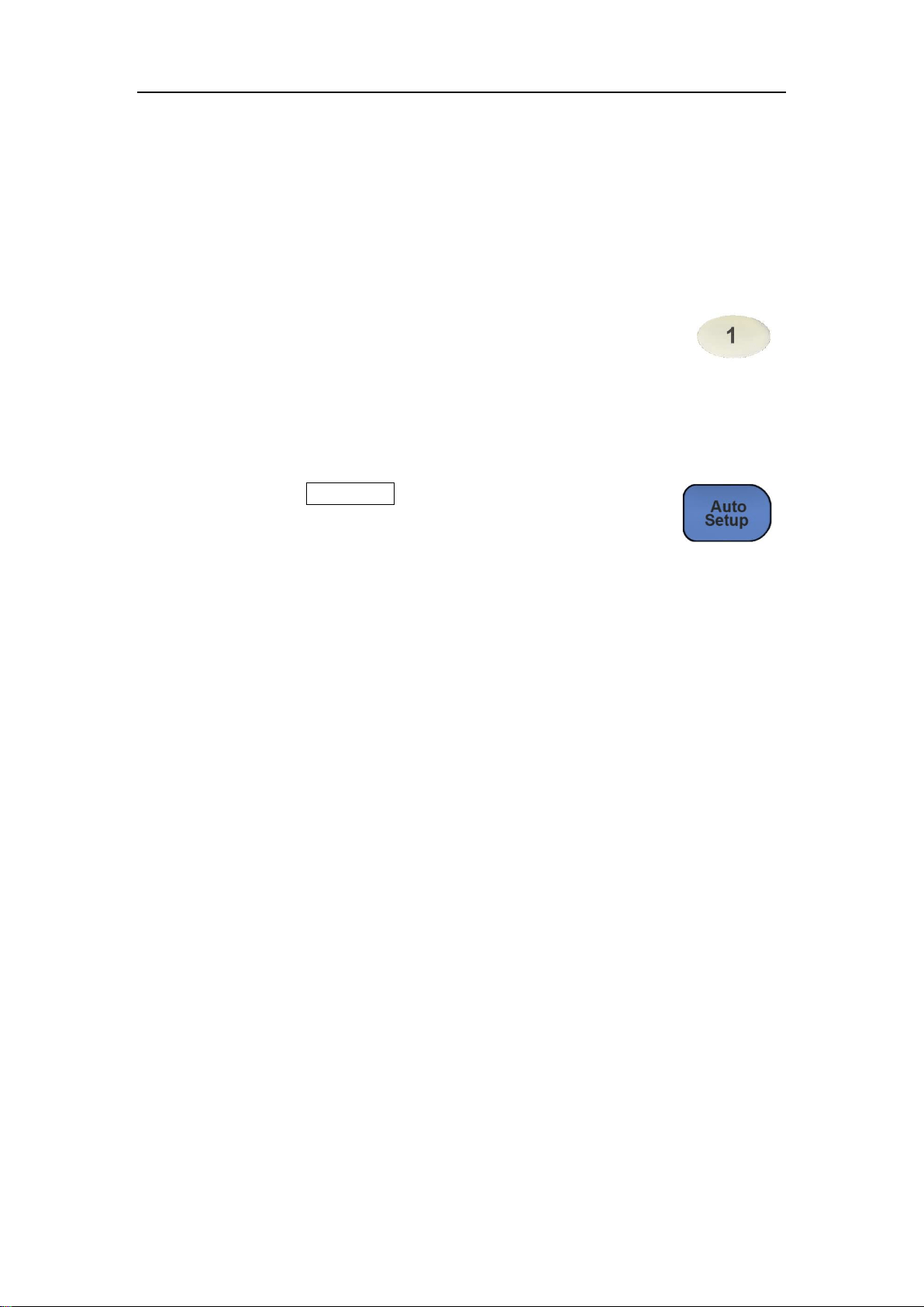
11 Quickly Capture the Signal
This is an example about how to acquire a signal quickly. In this example we
assume the signal is connected to channel 1 and channel 1 is turned off.
First, press channel 1 button to turn on channel 1. The LED
on the button lights, and the descriptor box of channel 1 is
displayed at the bottom of the screen.
Second, press the AutoSetup button. The oscilloscope will
automatically adjust the vertical scale, horizontal scale and
trigger level according to the input signal to get optimum
waveform display.
AutoSetup will not work on all signal types, especially time-varying bursts or
slow signals (< 100 Hz). If AutoSetup cannot achieve desired settings, you can
manually adjust the vertical, horizontal, and trigger systems. See the chapters
"Vertical Setup", "Horizontal and Acquisition Setup" and "Trigger" for details.
SDS5000X Series Digital Oscilloscope User Manual
51 / 2 3 6 W W W. S I G L E N T. C O M
12 Vertical Setup
12.1 Turn on/off a Channel
From the Front Panel
Push the channel button(1-4)to turn on the corresponding channel. Its
channel descriptor box and dialog box will appear on the display. Push the
same button again to disable the channel.
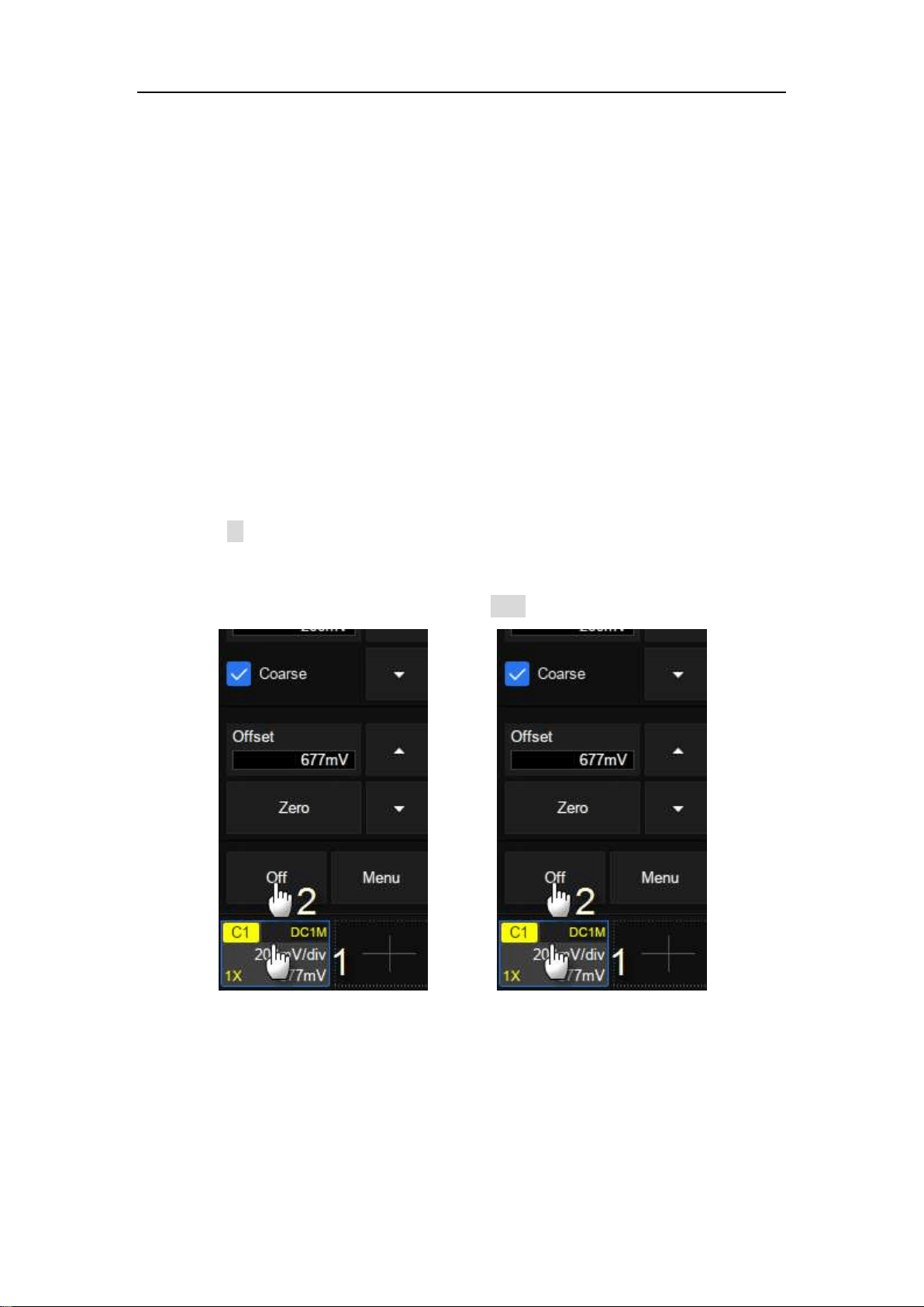
From the Touch Screen
Touch the + button and then select the expected channel to turn it on, and its
channel descriptor box and dialog box will appear on the display. Touch the
channel descriptor box and then touch the Off button to disable it.
Turn on C1
Turn off C1
12.2 Channel Setup
Touch the channel descriptor box, a quick dialog will pop up. Vertical scale and
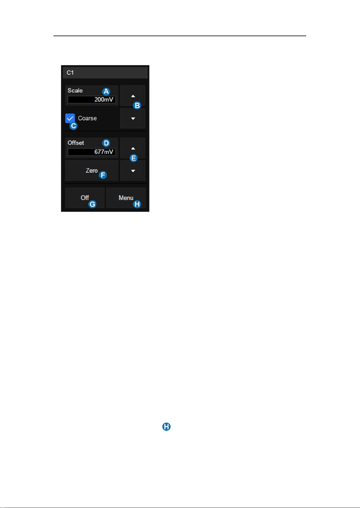
SDS5000X Series Digital Oscilloscope User Manual
52 / 2 3 6 W W W. S I G L E N T. C O M
offset can also be set from this dialog box.
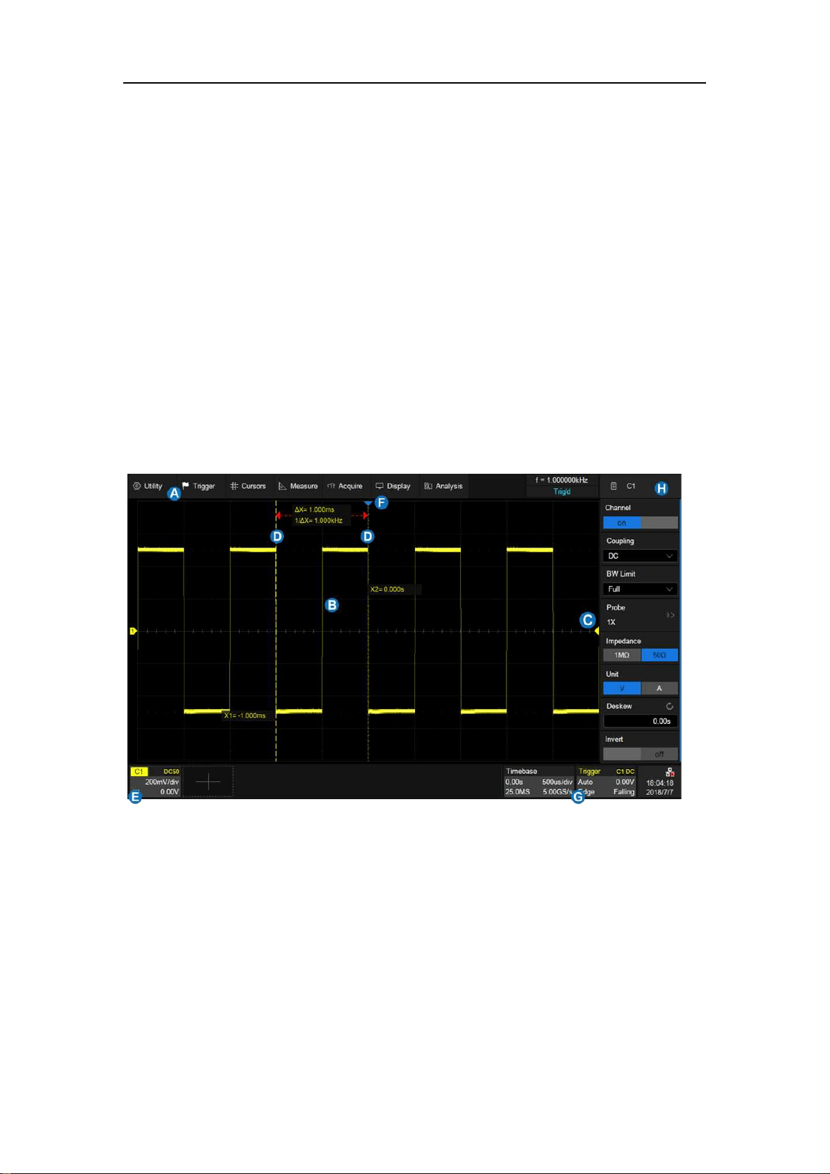
A. Touch the region to set the vertical
scale with universal knob or virtual
keypad
B. ▲ to increase the vertical scale and
▼ to decrease
C. Check to coarsely adjust the vertical
scale and uncheck to enable fine
adjustment
D. Touch the region to set the offset with
universal knob or virtual keypad
E. ▲ to increase the offset and ▼ to
decrease
F. Set the offset to zero
G. Disable the channel
H. Open the dialog box on the right side
The vertical scale can be adjusted in coarse or fine mode. Fine mode can
reach the full-scale display as close as possible, which can get the best
measurement accuracy in the vertical direction. The oscilloscope
automatically switches to fine mode when the vertical scale is controlled by
touch gesture.
Activating a channel or touching in the quick dialog of the channel recalls
the channel dialog box, displaying more parameters:
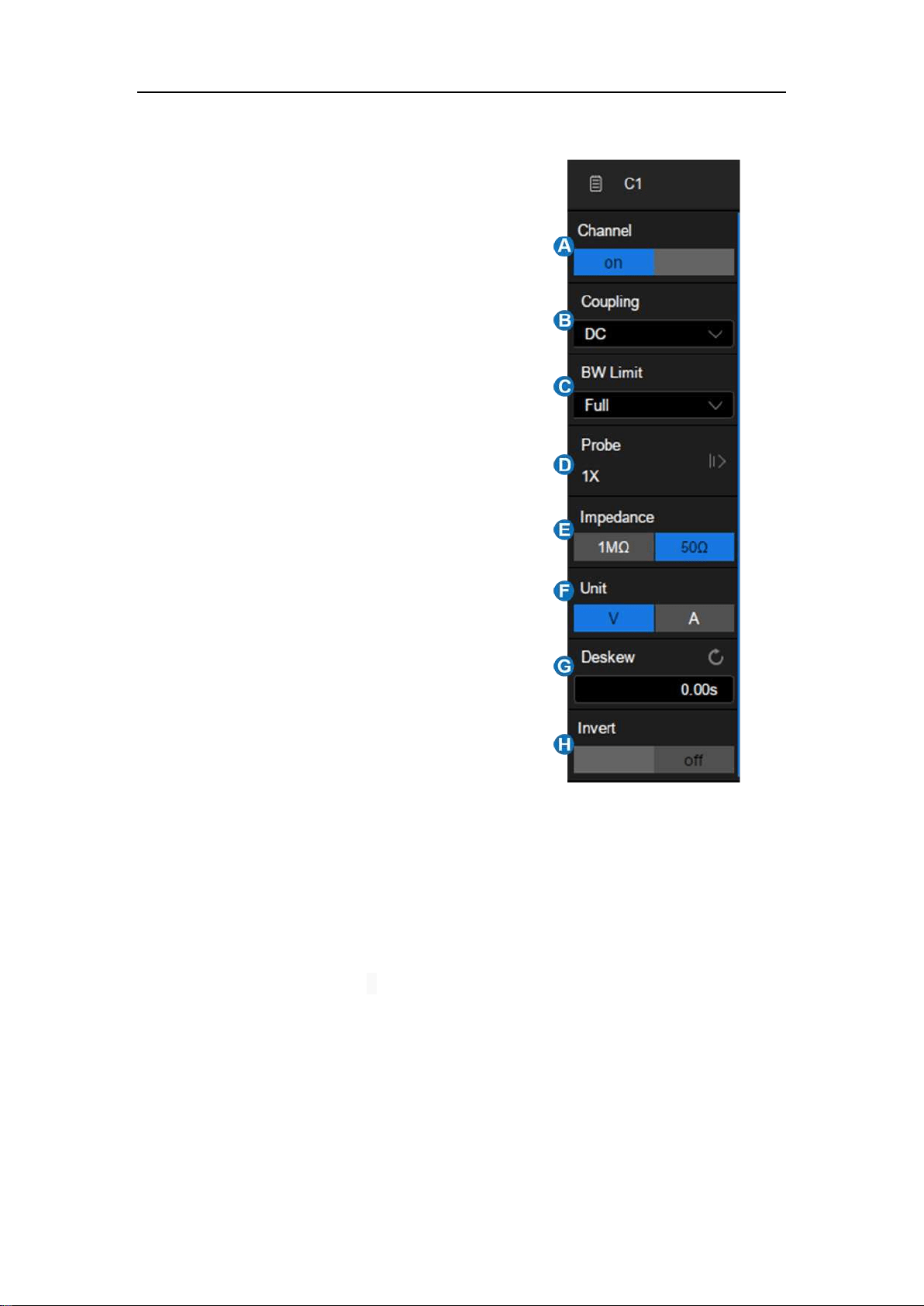
SDS5000X Series Digital Oscilloscope User Manual
53 / 2 3 6 W W W. S I G L E N T. C O M
A. Turn channel on/off
B. Coupling (DC, AC or GND)
C. Bandwidth limit (Full, 200 MHz or 20
MHz)
D. Probe attenuation (1X, 10X, 100X or
custom)
E. Impedance
F. Units for the channel
G. Deskew
H. Enable/disable invert
Coupling
DC: All of the input signal frequency components are passed to the display.
AC: The signal is capacitively coupled. DC signal components are rejected.
See the datasheet for details of the cut-off frequency. AC coupling is
suitable for observing AC signals with DC offset, such as power ripple.
GND: The channel is grounded by an internal switch. GND coupling is used
to observe the zero offset error of the analog channels, or determine the
source of noise in the waveform (from signal or from oscilloscope itself)

SDS5000X Series Digital Oscilloscope User Manual
54 / 2 3 6 W W W. S I G L E N T. C O M
Bandwidth Limit
Full bandwidth can pass through signals with high frequency components, but
it also means that noise with high frequency components can pass through.
When the frequency component of the interested signal is very low, better
signal-to-noise ratios (SNR) can be obtained by turning on a bandwidth limit.
The SDS5000X provides two bandwidth limit options: 20 MHz and 200 MHz.
Probe Attenuation
The SDS5000X provides 1X, 10X, 100X and custom probe attenuation factor
options. The custom value is between 10
-6
~10
6
. The oscilloscope will
automatically convert the vertical scale according to the current probe
attenuation factor. For example, the vertical scale of the oscilloscope under 1X
attenuation is 100 mV/div, and the vertical scale will be automatically set to
1V/div if the probe attenuation is changed to 10X. If a standard probe with
readout terminal is connected, the oscilloscope will automatically set the probe
attenuation to match the probe.
Impedance
1 MΩ: When a passive probe with high impedance is connected, the
impedance must be set to 1 MΩ, otherwise the signal will not be detected.
50 Ω: It is suitable for high frequency signals transmitted through 50 Ω
coaxial cables and can minimize the amplitude distortion caused by
impedance mismatching.
Unit
SDS5000X Series Digital Oscilloscope User Manual
55 / 2 3 6 W W W. S I G L E N T. C O M
Voltage unit "V" or current unit "A”. When using the current probe, the unit
should be set to "A".
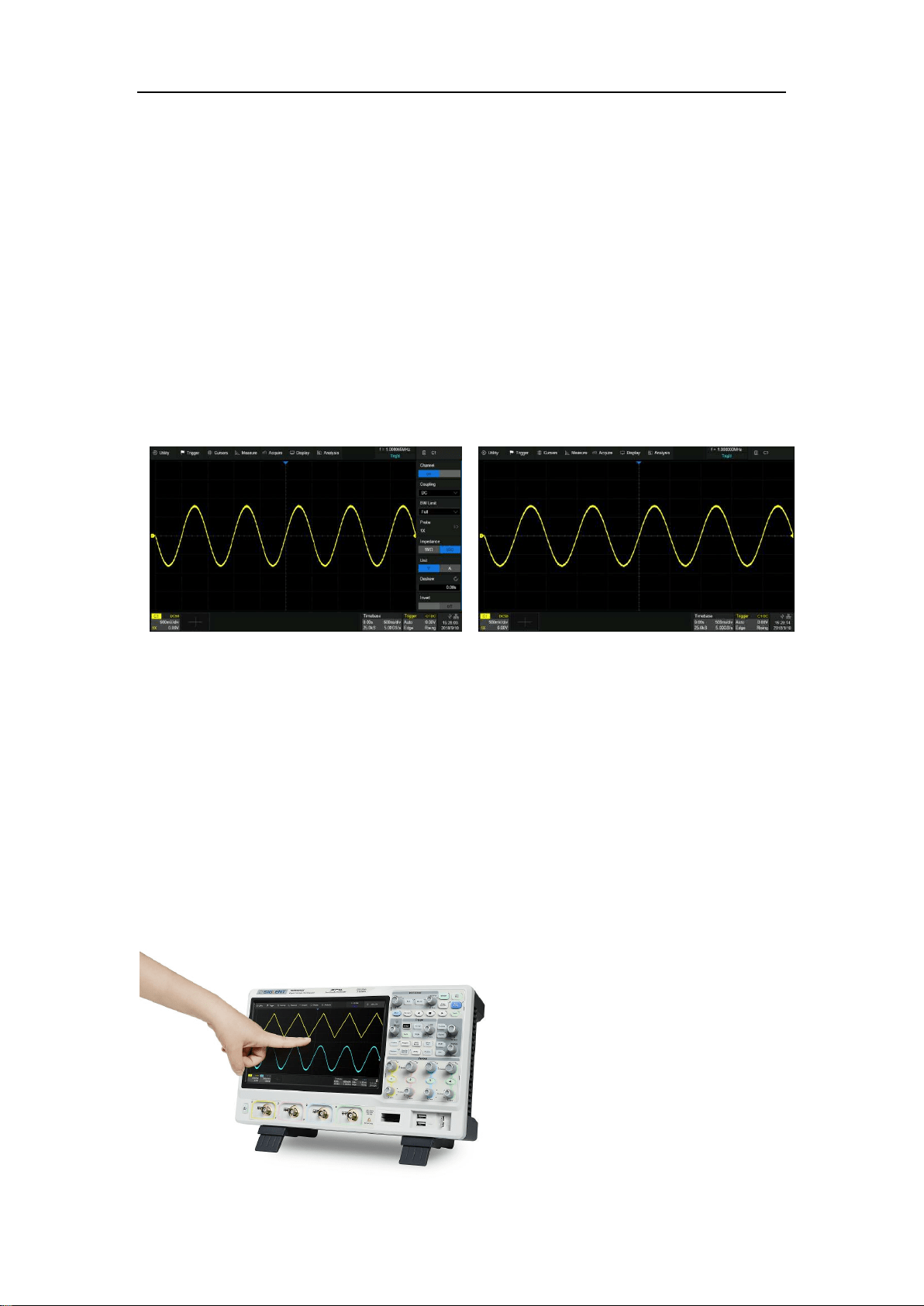
Deskew
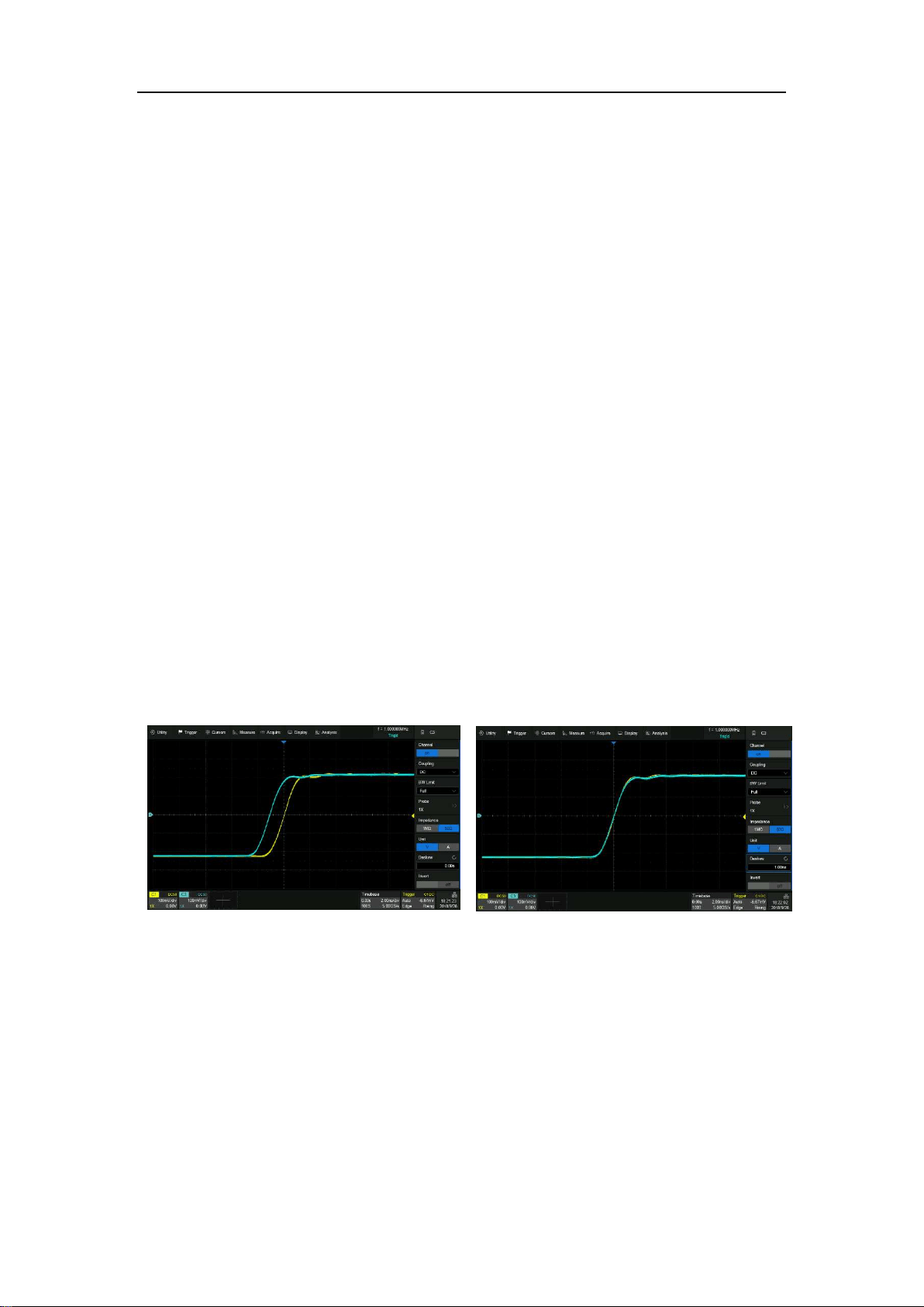
Due to the skew between channels, cables or probes, the delay of signals
passing through different measurement paths may be inconsistent. For
example, two coaxial cables with a 1 inch difference in length could introduce
a skew of more than 100 ps. In some scenarios (e.g. measuring the
setup/hold time between clock and data), it may be necessary to compensate
the skew between channels
.
The method of compensation: Probe the same signal simultaneously using
two channels (including the cables or probes that you intend to use for
measurements) and adjust the deskew parameter of one channel until the
waveforms of the two channels observed on the screen coincide horizontally.
Before deskew
After deskew
Note: When the channel with deskew compensation is the trigger source, the
trigger delay indicator does not change as the deskew value changes.
Invert
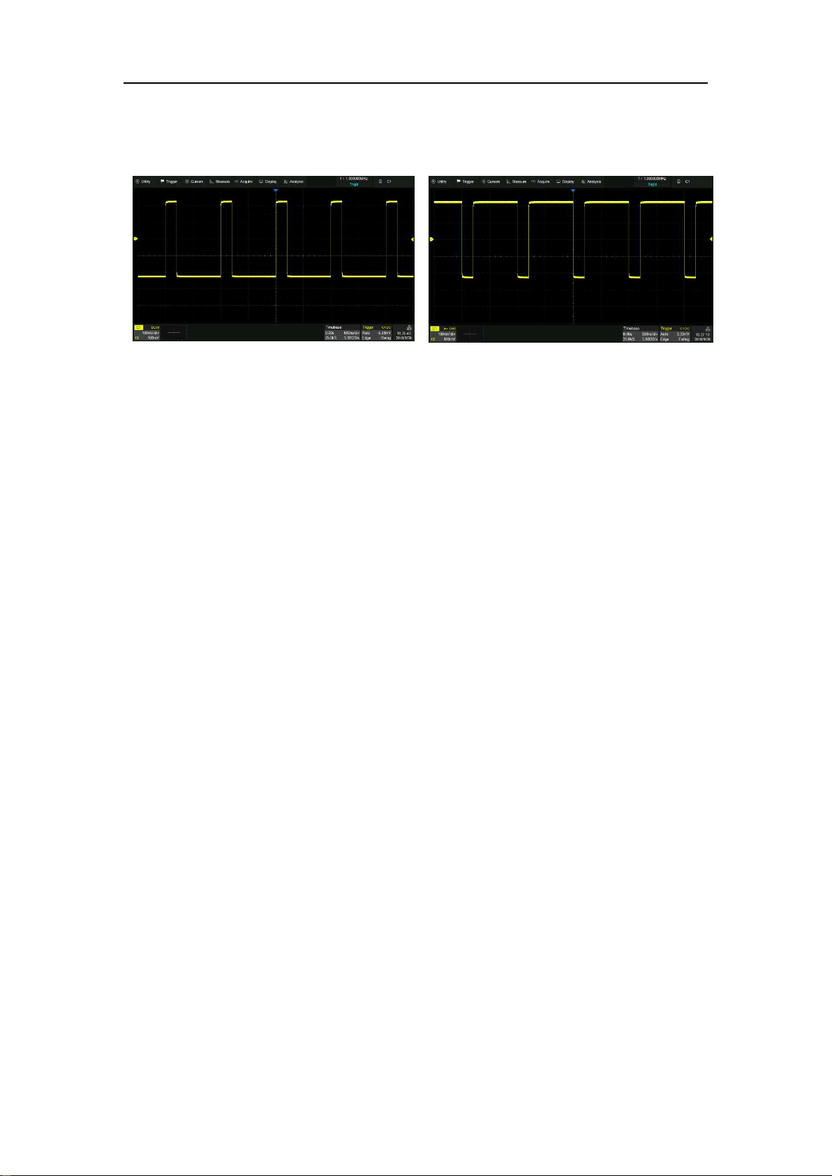
SDS5000X Series Digital Oscilloscope User Manual
56 / 2 3 6 W W W. S I G L E N T. C O M
When invert is enabled, the waveform is 180 degrees opposite to the earth
potential.
Before invert
After invert
SDS5000X Series Digital Oscilloscope User Manual
57 / 2 3 6 W W W. S I G L E N T. C O M
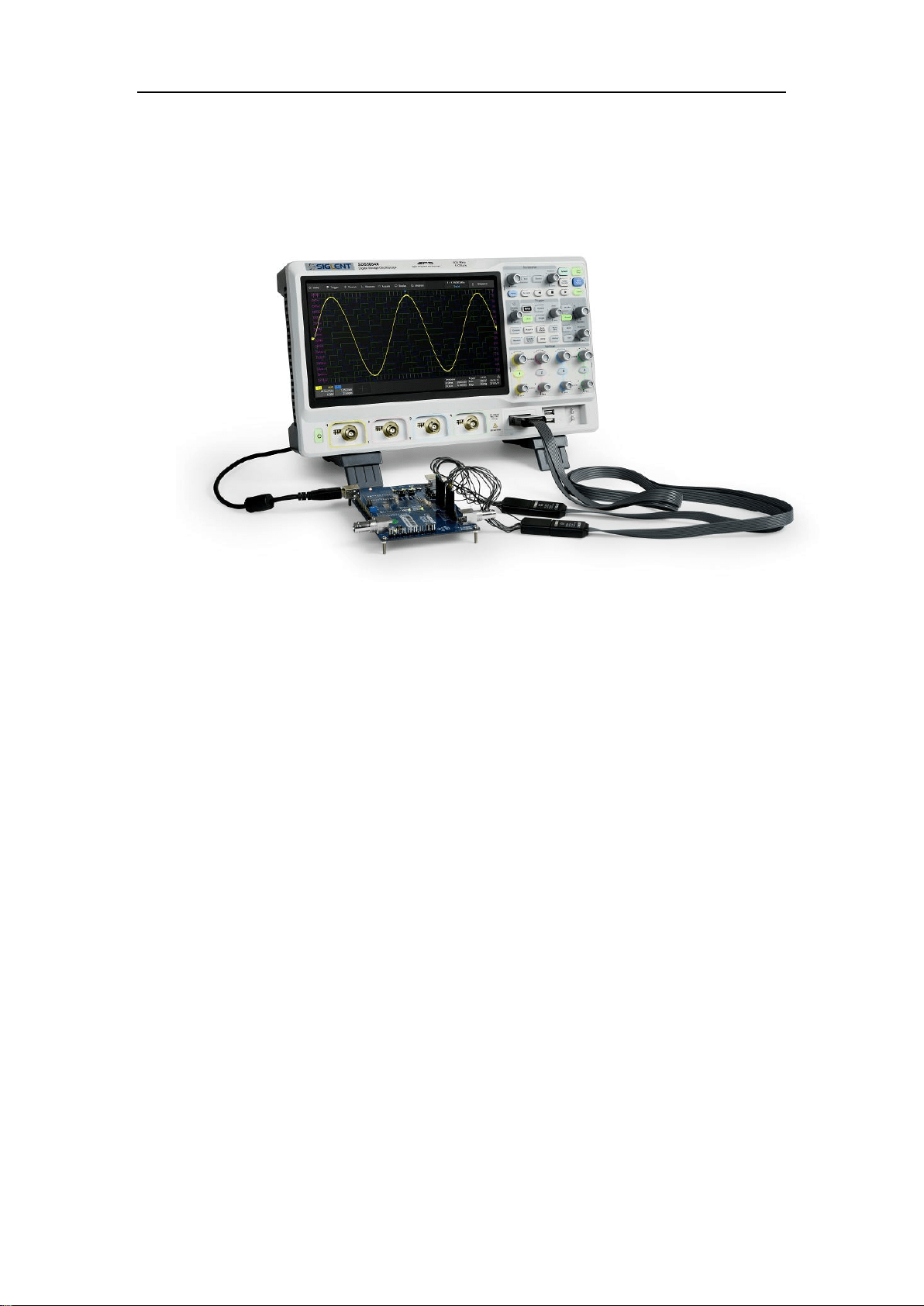
13 Digital Channels
13.1 Overview
SPL2016 Probe
The SPL2016 is a logic probe designed to monitor up to 16 digital signals at
once. The 16 digital channels are separated into two groups and each group
has its own threshold, making it possible to simultaneously view data from
different logic families.
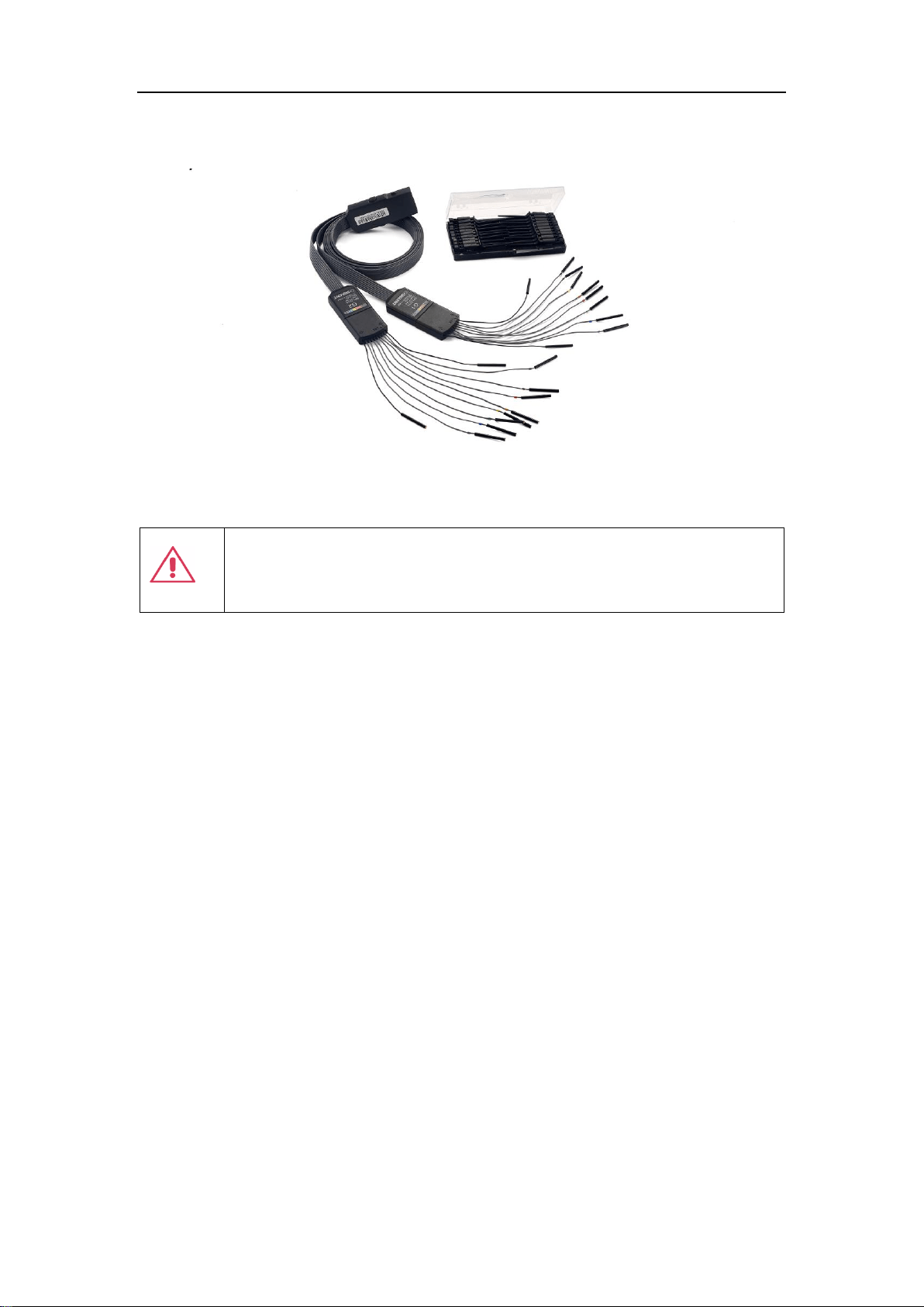
SDS5000X Series Digital Oscilloscope User Manual
58 / 2 3 6 W W W. S I G L E N T. C O M
Note: To avoid personal injury or damage to the logic probe and any
associated equipment, the following safety precautions should be noted.
The equipment shall be used only for the purposes specified by the
manufacturer. The SPL2016 probe is used only for SIGLENT's special series
of oscilloscopes. Protection mechanisms can be compromised if the way the
devices connected by the SPL2016 are not used for their intended purpose.
Connect and disconnect correctly. Excessive bending can damage the cable.
Do not use equipment in humid or explosive environment.
Only used indoors. The SPL2016 is designed to be used indoors and should
only be operated in a clean, dry environment.
Do not use the equipment when you suspect a problem. Do not use the
SPL2016 if any parts are damaged. Maintenance work shall be performed by
maintenance personnel with appropriate qualifications.
Keep product surface clean and dry.
SDS5000X Series Digital Oscilloscope User Manual
59 / 2 3 6 W W W. S I G L E N T. C O M
SDS-5000X-LA16 Option
The software option adds the following functions to the oscilloscope:
Digital channel acquisition and analysis - Acquire and analyze the
signals connected to the digital logic probe, including waveform display,
save, parameter measurement, etc.
Trigger on a digital channel - Trigger with the digital channel as the
trigger source, isolating events of interest.
Decode on a digital channel - Serial protocol decoding of a digital
channel requires the installation of the serial decode option.
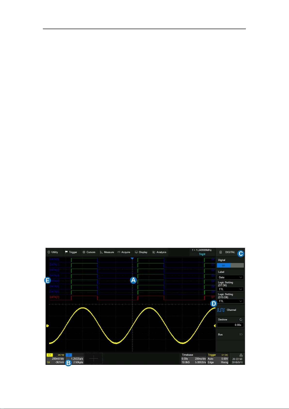
13.2 Enable/Disable the Digital Channels
Turning on or off the digital channels is very similar to analog channels. Digital
data can be stored as waveform files. Horizontal cursors and most of
horizontal measurements also apply to digital waveforms.

SDS5000X Series Digital Oscilloscope User Manual
60 / 2 3 6 W W W. S I G L E N T. C O M
A. Digital channel waveform display, which shares the same grid area
with the analog channels.
B. Digital channel descriptor box
C. Dialog box
D. Digital channel indicators. Up to 16 digital channels are organized in
two groups with different thresholds: D15~D8 and D7~D0. Every
channel can be turned on or off individually.
E. Labels, can be set to data, address or custom characters.
From the Front Panel
Press the Digital button on the front panel to turn on digital channels and
display the waveforms. Press again to turn off.
From the Touch Screen
Click + at the bottom of the display and select the "Digital" to turn on; click
the digital channel descriptor box, and clicking Off on the pop-up menu to turn
off. Refer to the operation in the chapter "Vertical Setup" for details.
13.3 Digital Channel Setup
Touch the digital descriptor box, then the quick menu of digital channel
settings pops up above the descriptor box. In the menu height and position of
digital channels can be set:
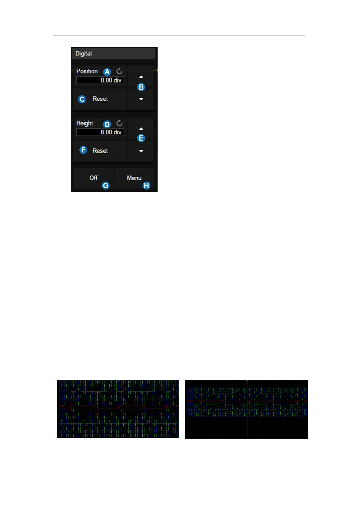
SDS5000X Series Digital Oscilloscope User Manual
61 / 2 3 6 W W W. S I G L E N T. C O M
A. Upper position limit of the digital
channel display area. You can use the
universal knob or virtual keypad to set
it. Decrease the height to provide
more adjustment area.
B. ▲ to increase position and ▼ to
decrease the channel location.
C. Reset the position to default value
D. The range in height of the digital
channels display area. You can use
the universal knob or virtual keypad to
set it. If the display height covers all of
the available divisions, there will not
be room to adjust the position.
E. ▲ to increase and ▼ to decrease the
number of divisions occupied by the
digital channels
F. Reset the height to default value
G. Turn off the digital channels
H. Open digital dialog box on the right side
Height = 8 div, Position = 0 div
Height = 4 div, Position = 1 div
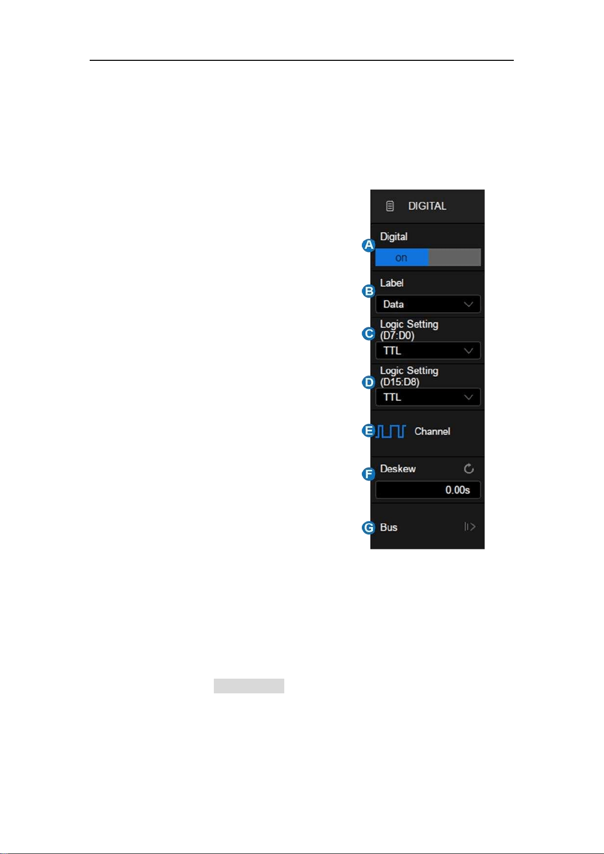
SDS5000X Series Digital Oscilloscope User Manual
62 / 2 3 6 W W W. S I G L E N T. C O M
The quick menu only covers the height range and position of the digital
channels display area. More setting can be found in the dialog box.
A. Turn on/off the digital channels
B. Labels, can be set to data, address or
custom characters.
C. Logic threshold of D7~D0. The
oscilloscope will automatically set the
threshold according to specified logic
family, or user can set the threshold
by manual using the Custom option.
D. Logic threshold of D15~D8
E. Set the channels to be displayed
F. Deskew setting
G. Bus setting
Logic Threshold Setting
The threshold level determines how the input signal is evaluated. The threshold
level can be set in the Logic Setting. The input voltage less than the threshold
is recognized as a '0', and the input voltage greater than the threshold is
recognized as a ‘1’.
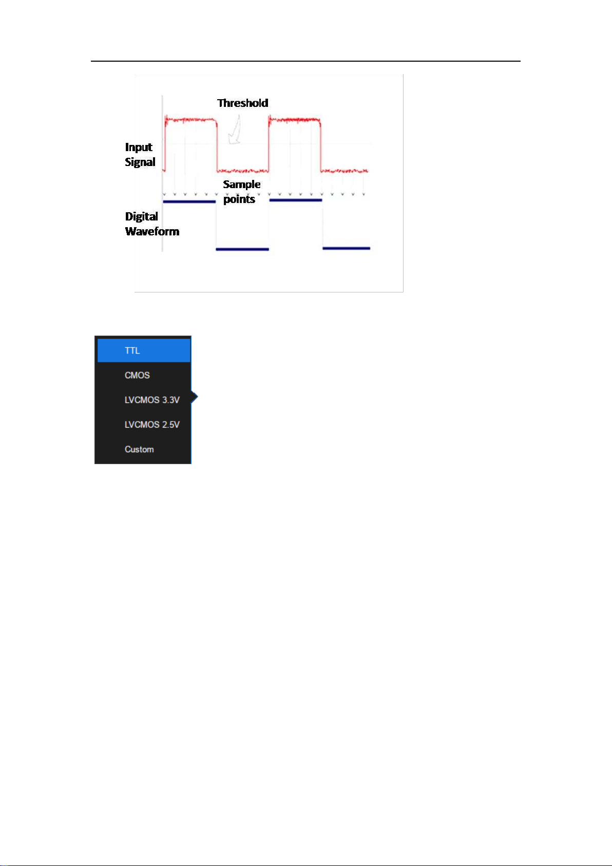
SDS5000X Series Digital Oscilloscope User Manual
63 / 2 3 6 W W W. S I G L E N T. C O M
The configurable logical level includes TTL, CMOS,
LVCMOS 3.3 V, LVCMOS 2.5 V and Custom.
The setting range of custom threshold is -10.0 V to + 10.0
V.
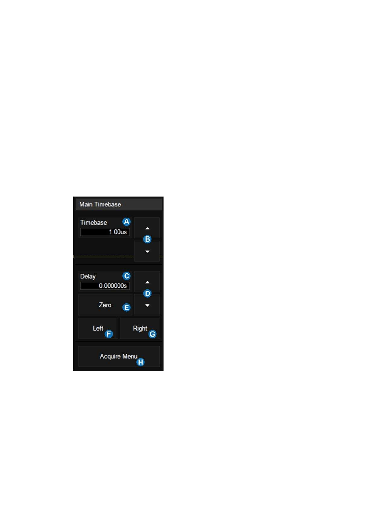
SDS5000X Series Digital Oscilloscope User Manual
64 / 2 3 6 W W W. S I G L E N T. C O M
14 Horizontal and Acquisition Setup
14.1 Timebase Setup
The timebase setup is used to adjust the scale and offset of the X (horizontal)
axis. This setting applies to all analog, digital channels and all math traces
except FFT.
Touch the timebase descriptor box, the quick menu of the timebase settings will
pop up. In the menu timebase (horizontal scale), delay and other parameters
can be set.
A. Set the horizontal scale (timebase) by
the virtual keypad
B. ▲ to increase and ▼ to decrease the
horizontal scale
C. Set the trigger delay by the virtual
keypad
D. ▲ to increase and ▼ to decrease the
trigger delay
E. Set the trigger delay to zero
F. Set the trigger delay to the left part of
the screen
G. Set the trigger delay to the right part of
the screen
H. Open the Acquire dialog box
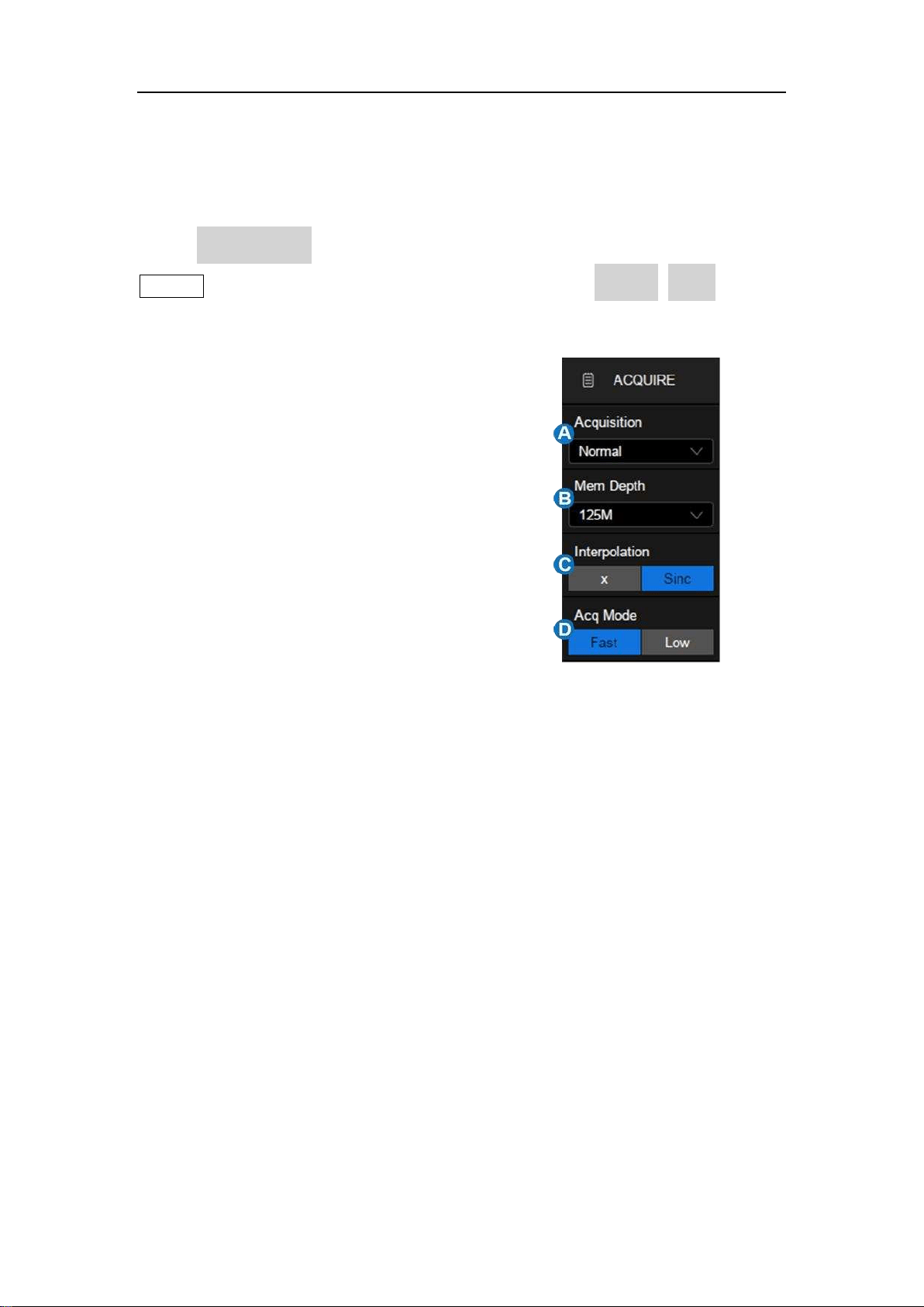
SDS5000X Series Digital Oscilloscope User Manual
65 / 2 3 6 W W W. S I G L E N T. C O M
14.2 Acquisition Setup
14.2.1 Overview
Touch Acquire Menu on the quick menu of the timebase settings, or press the
Acquire button on the front panel, or touch the menu bar Acquire>Menu to recall
the Acquire dialog box on the right side.
A. Select the acquisition mode
(Normal/Peak/Average/Eres)
B. Select the maximum memory depth
C. Select the interpolation mode
D. Select the Acq mode
Acquisition: See the section "Acquisition" for details.
Memory Depth: The maximum memory depth that can be supported.
According to the formula "acquisition time = sample points x sample interval",
setting a larger memory depth can achieve a higher sample rate for a given
timebase, but more samples require more processing time, degrading the
waveform update rate. With 250 Mpts memory depth, SDS5000X can still run
at full sample rate (5 GSa/s) even when set to the 5 ms/div timebase.
Note: The memory depth here is the upper limit of the memory space allocated
by the oscilloscope. The actual sample points is related to the current timebase

SDS5000X Series Digital Oscilloscope User Manual
66 / 2 3 6 W W W. S I G L E N T. C O M
and may be less than memory depth. The actual sample points information can
be obtained in the timebase descriptor box (see the section "Timebase and
Trigger " for details).
The maximum memory depth in single channel mode is 2 times that of the dual
channel mode, as the following table:
Single Channel
Mode
Dual Channel
Mode
250 k
125 k
1.25 M
625 k
2.5 M
1.25 M
12.5 M
6.25 M
25 M
12.5 M
125 M
62.5 M
250 M
125 M
Single channel mode: Only one of C1/C2 is turned on, and only one of C3/C4
is turned on.
Dual channel mode: Both C1/C2 are turned on, or both C3/C4 are turned on.
Interpolation-- At small timebase settings, the number of original points on the
screen may be less than the number display pixels in the grid area, so
interpolation is necessary to display continuous waveform. For example, at 1
ns/div timebase and 5 GSa/s sample rate, the number of original points is 50,
but the grid area includes 1000 horizontal pixels. In this case, the oscilloscope
needs to interpolate the original points by 20.
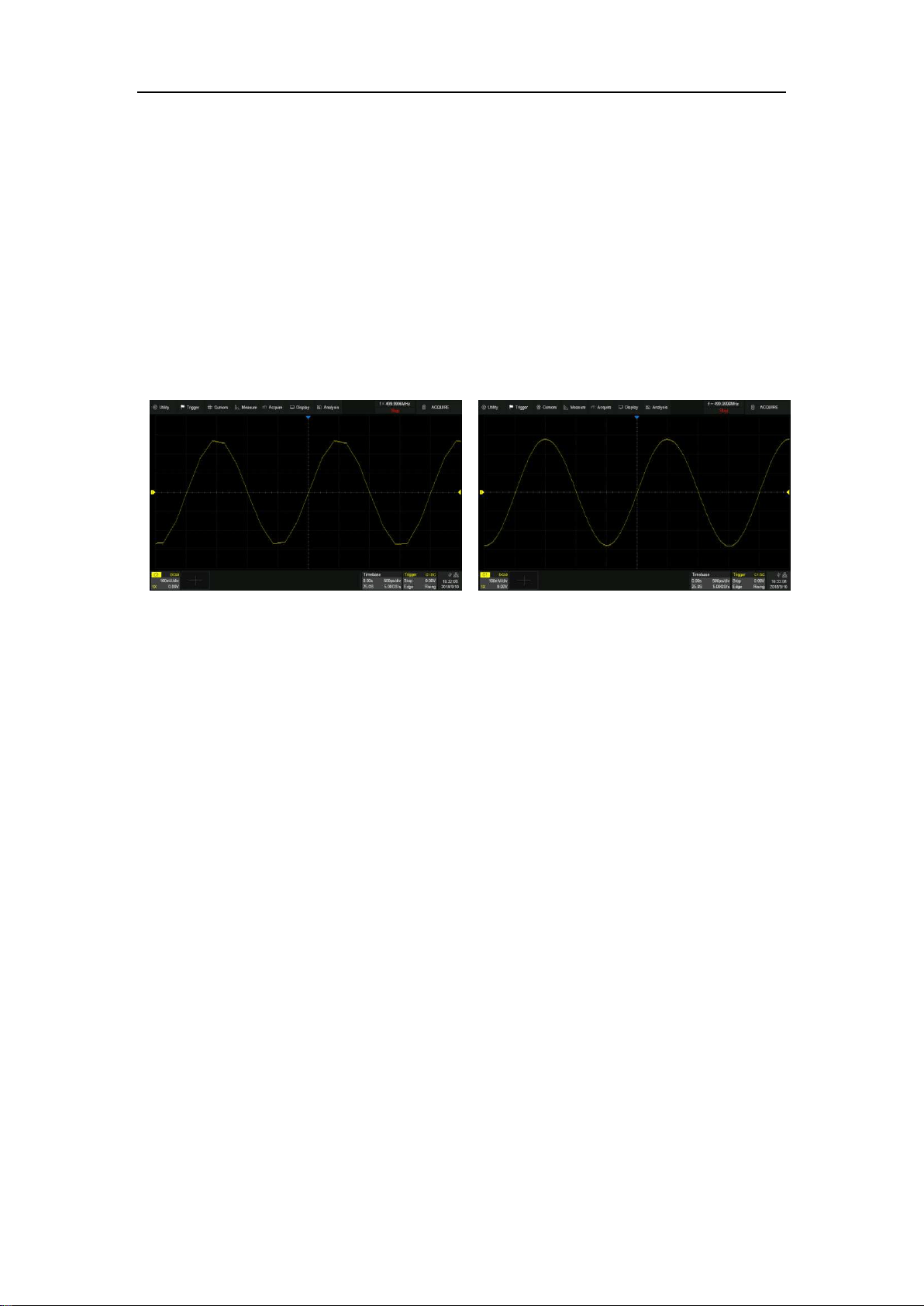
SDS5000X Series Digital Oscilloscope User Manual
67 / 236 W W W. S I G L E N T. C O M
X: Linear interpolation, the simplest way of interpolation, connects two
original points with a straight line.
Sinc: Sin(x)/x interpolation, the original point is interpolated according to
the Nyquist reconstruction formula, which has a good time-domain recovery
effect for sine wave. But for step signals/fast rise times, it will introduce false
overshoot due to the Gibbs phenomenon.
X Interpolation
Sinc Interpolation
Acq mode: "Fast" is the default setting. The SDS5000X provides a very high
waveform update rate in fast mode. "Slow" mode will slow down the waveform
update on purpose.
14.2.2 Acquisition
The acquisition mode is used to determine how to acquire and process the
signal.
Normal: The oscilloscope samples the signal with equal time interval. For most
waveforms, the best display effect can be obtained using this mode.
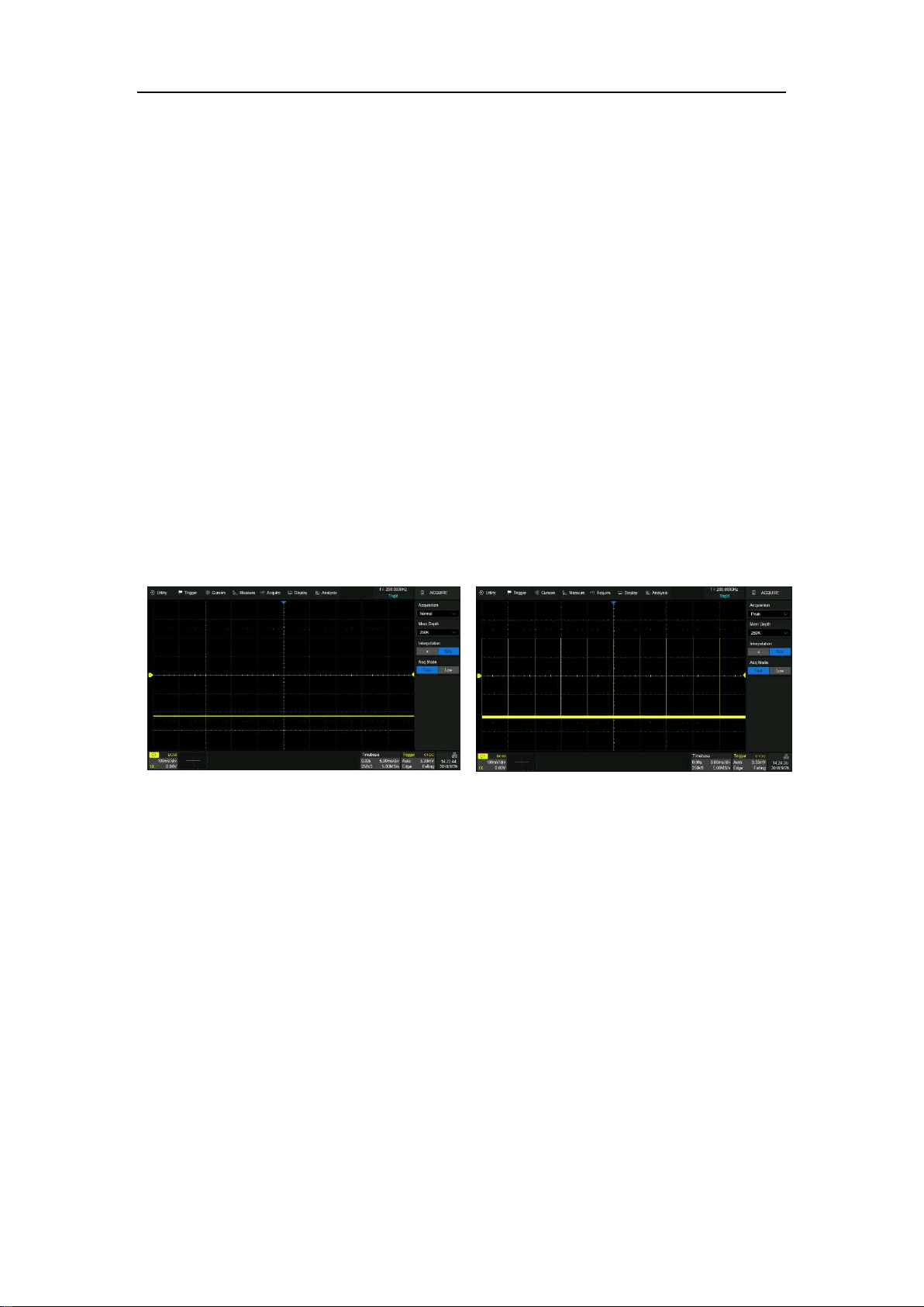
SDS5000X Series Digital Oscilloscope User Manual
68 / 2 3 6 W W W. S I G L E N T. C O M
Peak: Peak detect mode. The oscilloscope acquires the maximum and
minimum values of the signal within the sample interval so the peak (maximum
– minimum) in the interval is obtained. This mode is effective to observe
occasional narrow pulses or spurs with low sample rate, but the noise displayed
is larger. In peak mode, the oscilloscope will display all pulses with a pulse width
longer than 400 ps.
In the following example, a narrow pulse sequence with a pulse width of 3.4 ns
and a period of 200 Hz is sampled at 5 MSa/s sample rate in normal mode and
peak mode. As we can see, because the sample interval (200 ns) is much larger
than the pulse width (3.4 ns), it is difficult to capture the narrow pulses in normal
mode, but peak mode can ensure that each pulse is captured.
Normal mode
Peak mode
Average: The oscilloscope accumulates multiple waveform frames and
calculates the average as the result. If a stable trigger is available, the resulting
average has a random noise component lower than that of a single-shot record.
The more frames that are accumulated, the lower the noise is. For the
SDS5000X, average processing is implemented by hardware engine, so it can
still maintain a high waveform update rate when the acquisition mode is set to
average.
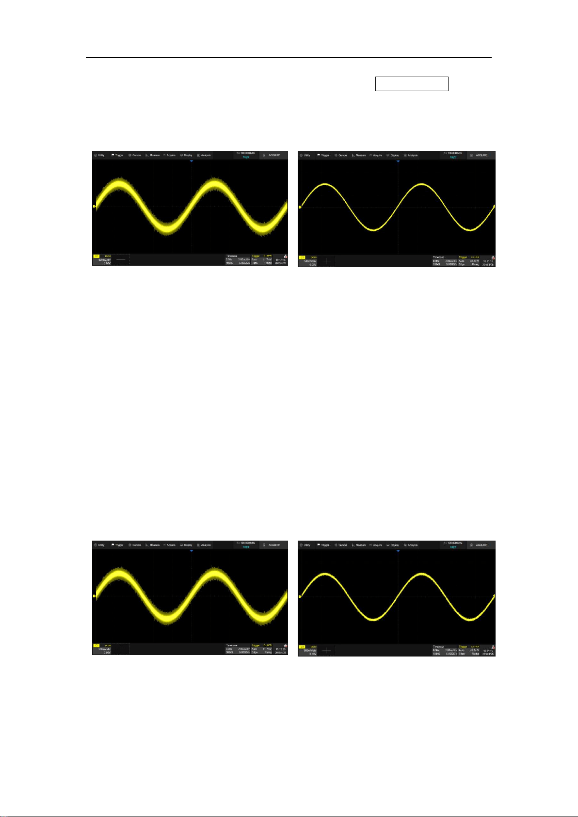
SDS5000X Series Digital Oscilloscope User Manual
69 / 2 3 6 W W W. S I G L E N T. C O M
You can reset the accumulated average by pushing the Clear Sweeps button
on the front panel.
Normal mode
Average mode(32)
Note: Average acquisition is only valid for periodic signals, and it is important
to ensure that the waveform is triggering in a stable way when using average
mode.
Eres: Enhanced resolution mode. The oscilloscope filters the sample, which
rejects noise in the high frequency domain, so the signal-to-noise ratio (SNR)
is improved. As a result, the effective number of bits (ENOB) of the oscilloscope
is enhanced. For the SDS5000X, Eres processing is implemented by the
hardware engine, so it can still maintain a high waveform update rate when the
acquisition mode is average.
Normal mode
Eres mode (3-bit)
Eres acquisition does not require the signal to be periodic, nor does it require
SDS5000X Series Digital Oscilloscope User Manual
70 / 2 3 6 W W W. S I G L E N T. C O M
stable triggering, but due to the digital filtering, the system bandwidth of the
oscilloscope will degrade in Eres mode. The higher the enhanced bits, the lower
the bandwidth. The following table shows the relationship between Eres bits
and bandwidth:
Eres Bits
-3dB bandwidth
0.5
0.25*Sample rate
1
0.115* Sample rate
1.5
0.055* Sample rate
2
0.028* Sample rate
2.5
0.014* Sample rate
3
0.007* Sample rate
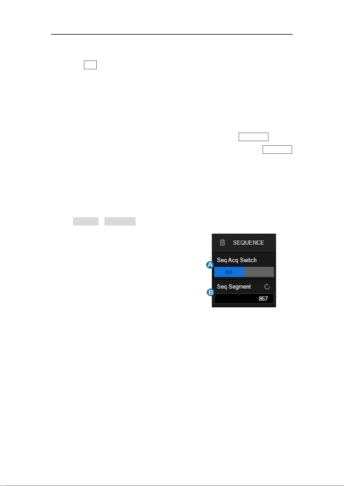
SDS5000X Series Digital Oscilloscope User Manual
71 / 2 3 6 W W W. S I G L E N T. C O M
14.2.3 Roll Mode
Press the Roll button on the front panel to enter roll mode. In this mode, the
waveform moves across the screen from right to left, similar to a strip chart
recorder. The horizontal delay control of the waveform will be disabled when
roll mode is active. It only operates at timebase values of 50 ms/div and above.
If you would like to stop the display in Roll mode, press the Run/Stop button.
To clear the display and restart an acquisition in Roll mode, press the Run/Stop
button again.
14.2.4 Sequence
Touch Acquire > Sequence to recall sequence dialog box.
A. Turn on or off sequence
B. Set the segment
Sequence mode is a fast acquisition mode, which divides the memory depth to
multiple segments (up to 100,000), each of which stores a single shot. In
sequence mode the oscilloscope only acquires and stores data without
processing and displaying, until the specified segments are acquired. As a
result, the dead time between trigger events is minimized, thus greatly
improving the waveform update rate. If sequence mode is enabled, the display
will not update until all of the sequences have been acquired. The SDS5000X
can achieve a minimum 2 us trigger interval in Sequence mode, corresponding
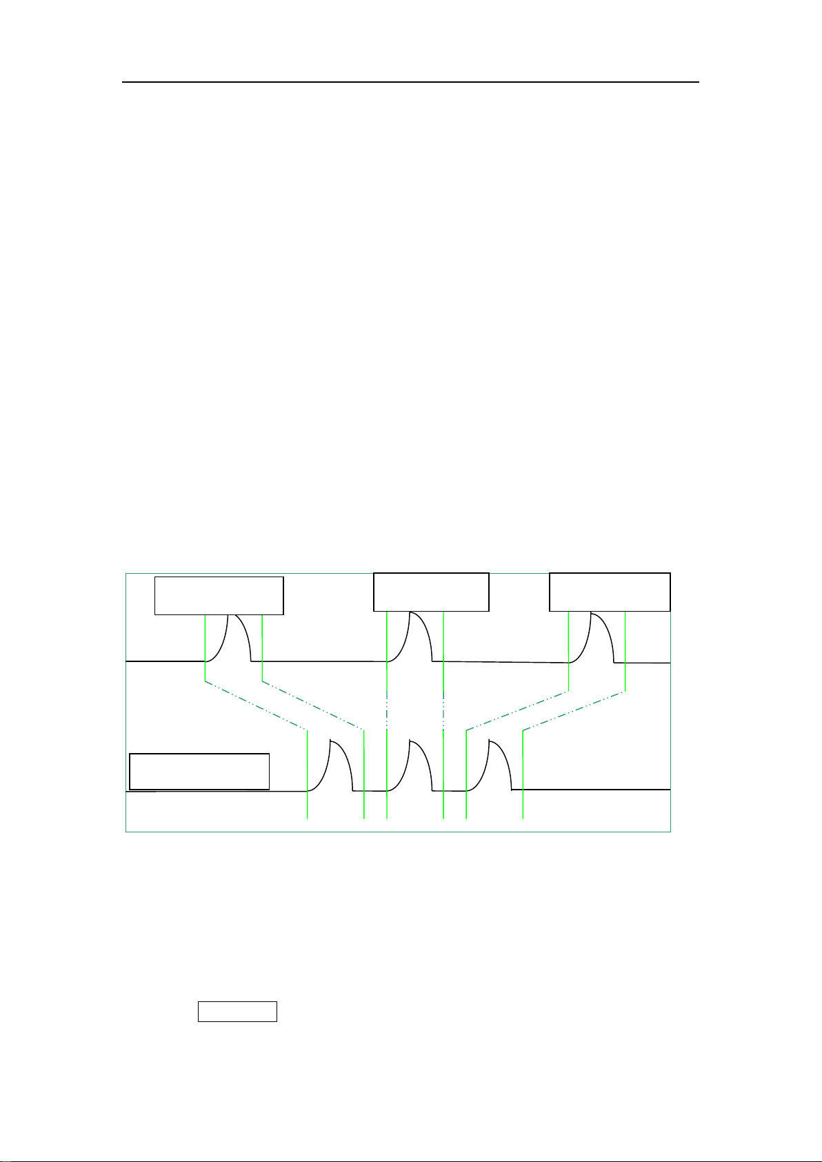
SDS5000X Series Digital Oscilloscope User Manual
72 / 2 3 6 W W W. S I G L E N T. C O M
to a waveform update rate of 500,000 wfm/s.
After the acquisition is finished, the oscilloscope will map all the segments
together to the screen. If you need to view and analyze each frame separately,
history mode will help (see the section "History" for details). History mode
provides timestamp labels for each segment.
In addition to minimizing the dead time, another advantage of Sequence mode
is that it can capture and record rare events over long time periods. The
oscilloscope can capture multiple events that satisfy the trigger conditions,
ignoring the periods of no interest between adjacent events, thus maximizing
the use of waveform memory. You can use the full accuracy of the acquisition
timebase to measure selected segments.
Example:
Input a pulse sequence with a period of 50 ms to C1. Rise time of the pulse is
2 ns, while fall time is 100 ns; pulse width is 108 ns, and amplitude is 1.6 Vpp.
Press the AutoSetup button on the front panel.
Sequence N
Stored Waveform
Sequence N+1
Sequence N-1
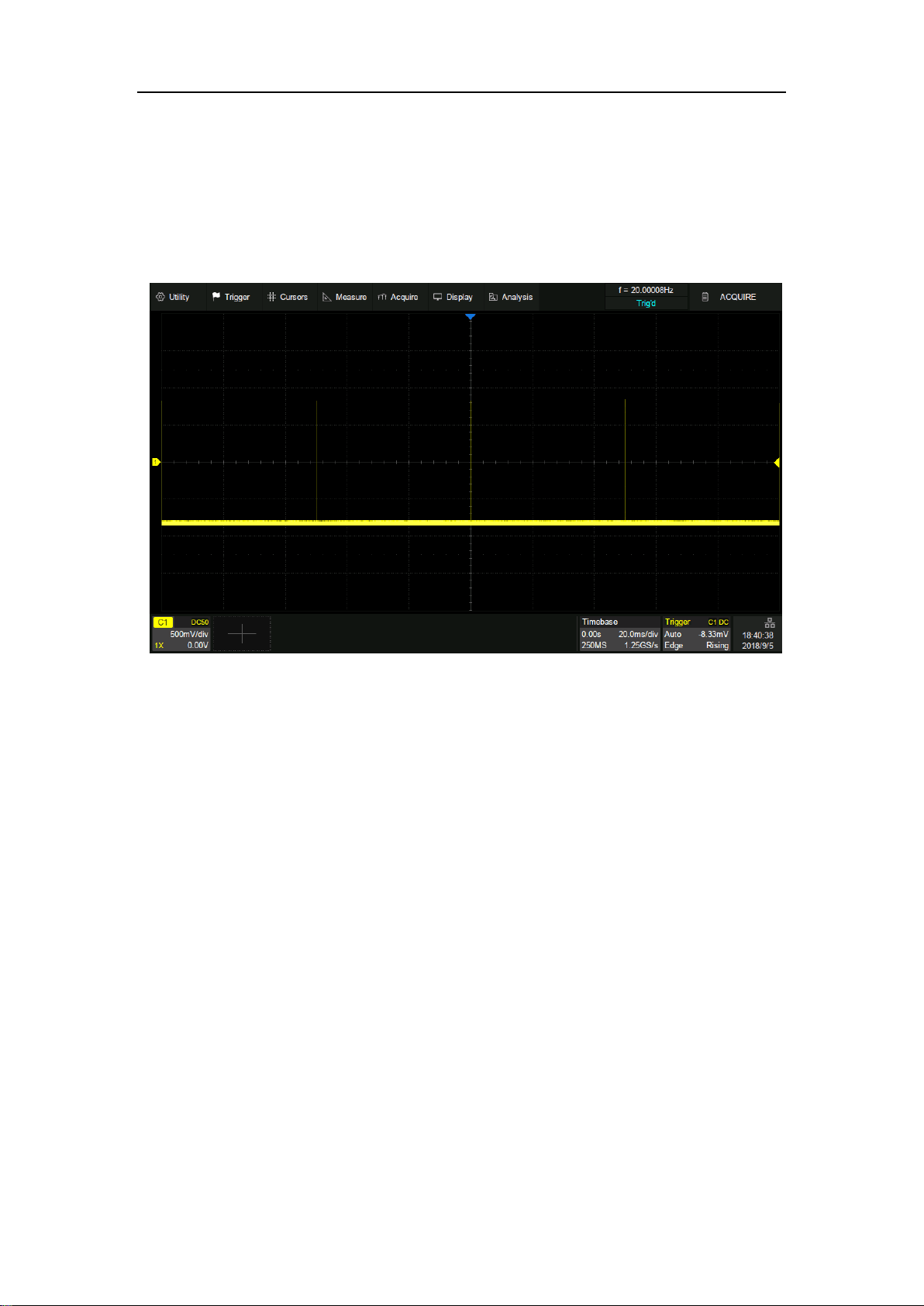
SDS5000X Series Digital Oscilloscope User Manual
73 / 2 3 6 W W W. S I G L E N T. C O M
Set the coupling mode of C1 to DC50Ω, and vertical scale to 500 mv/div, vertical
offset to 0. Set the trigger level to 0.
In normal mode, 5 pulses can be obtained on the screen with the sample rate of
1.25GSa/s at the maximum memory depth.
Set the trigger mode to "Single", the timebase to 50 ns/div. Turn on the
Sequence mode, and set the segments to maximum (53,969 in this example,
up to 100,000 depending on the number of samples at the current time base).
Wait patiently until the acquisition completes, then all the waveforms satisfying
the trigger conditions are displayed onto the screen.
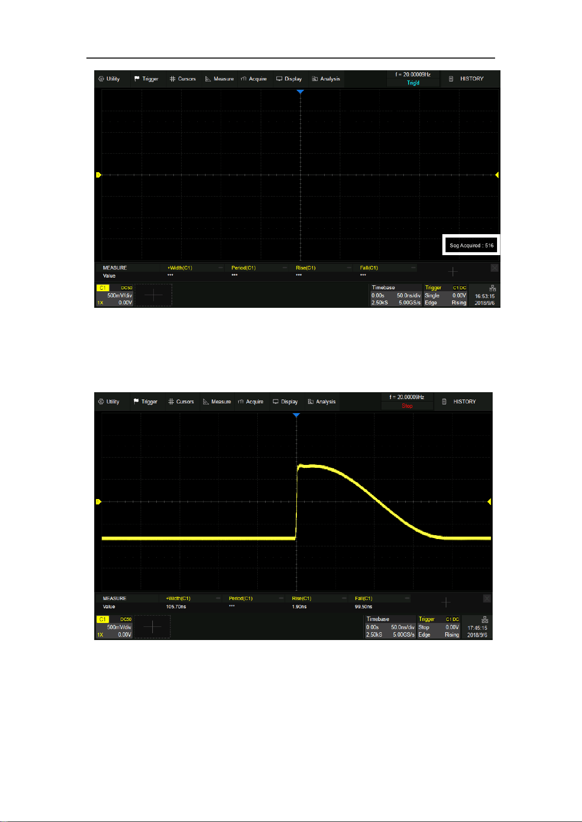
SDS5000X Series Digital Oscilloscope User Manual
74 / 2 3 6 W W W. S I G L E N T. C O M
In Sequence mode, there is no waveform displayed on the screen until the
acquisition is completed. During acquisition, there is a counter on the screen
indicating the number of segments that have been acquired.
In the example, 53969 pulses can be obtained with the sample rate of 5 GSa/s at the
maximum memory depth.
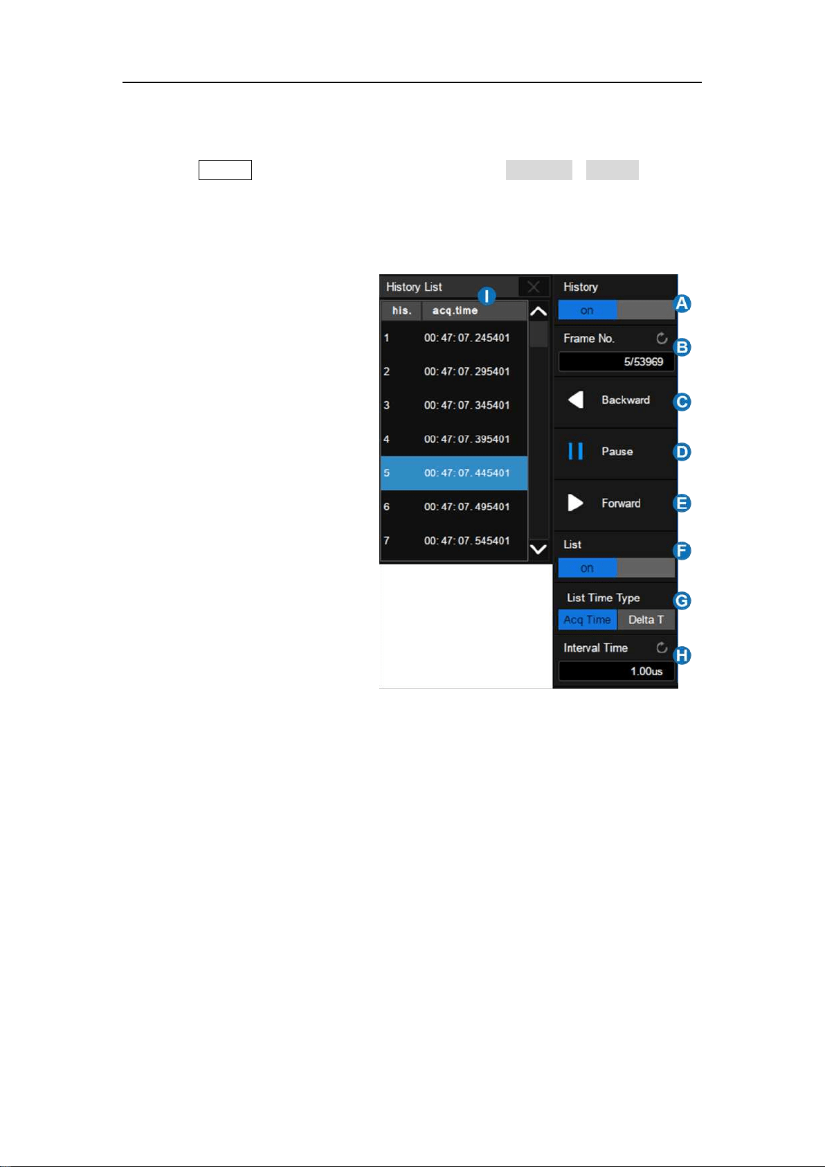
SDS5000X Series Digital Oscilloscope User Manual
75 / 2 3 6 W W W. S I G L E N T. C O M
14.3 History
Press the History button on the front panel or touch Analysis > History to
recall history dialog box.
A. Turn on or off history
mode
B. Specify the frame
index
C. Play backward
automatically
D. Pause
E. Play forward
automatically
F. Turn on or off the list
G. List time type
H. Set the time interval
between two frames
when playing
automatically
I. List, displays the
frame index and time
label for each frame.
The oscilloscope automatically stores acquired frames. It can stores up to
100,000 frames but the number may vary due to the memory depth and
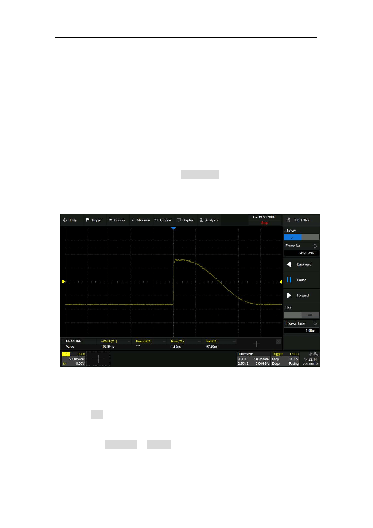
SDS5000X Series Digital Oscilloscope User Manual
76 / 2 3 6 W W W. S I G L E N T. C O M
timebase settings. Turn on history mode, then the stored frames can be recalled
and measured.
Continue with the example in the section above. In Sequence mode, all
waveforms that satisfy the trigger conditions are mapped to the display. If you
need to observe a single frame, you can use history mode.
To enable history mode, touch the Frame No. area twice, then the virtual
numeric keypad pops up. Input the number "5412" to specify the 5412th
segment (frame).
Observing the 5412th frame captured by Sequence in history mode
Touch the List area, turn on the list, in which the time label corresponding to the
5412th waveform is displayed. The time resolution is microseconds. Time label
types includes Acq Time or Delta T, Acq Time corresponds to the absolute time
of the frame, synchronized with the real-time clock of the oscilloscope; Delta T
is the acquisition time interval between adjacent two frames, it is shown as 50
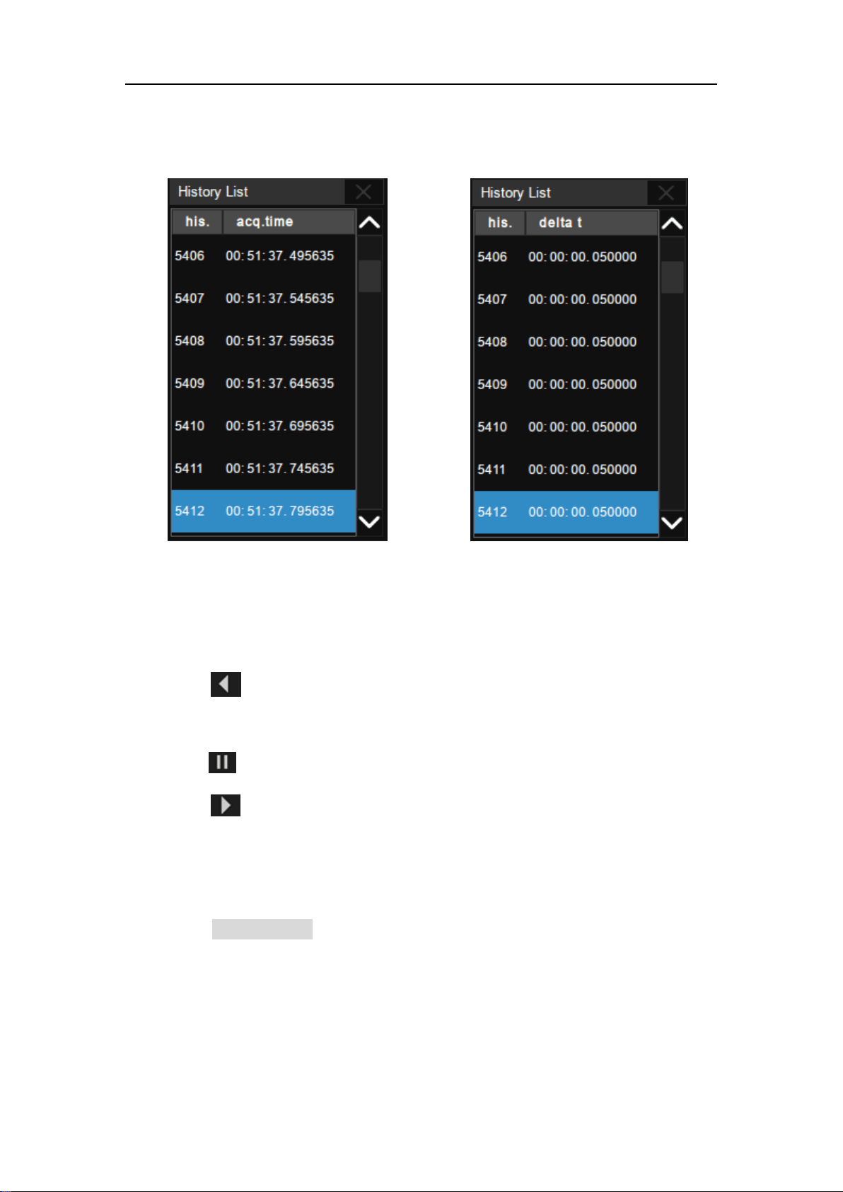
SDS5000X Series Digital Oscilloscope User Manual
77 / 2 3 6 W W W. S I G L E N T. C O M
ms in the following diagram, which is consistent with the period of the actual
waveform.
Acq Time label
Delta T label
In addition to manually specifying a frame, history mode supports auto play:
Press the softkey to replay the waveform from the current frame to the
first.
Press the softkey to stop replay.
Press the softkey to replay the waveform from the current frame to the
last.
Touch the Interval Time area to control the speed of automatic play. In the
process of automatic play, the list will automatically scroll to the current frame.
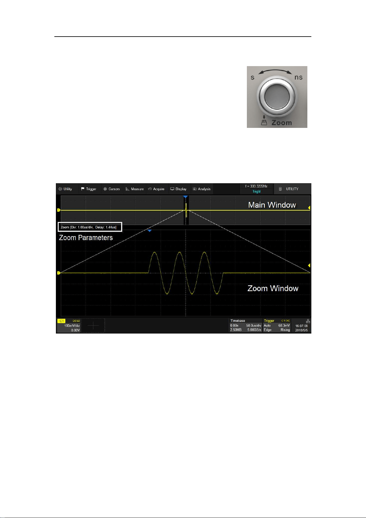
SDS5000X Series Digital Oscilloscope User Manual
78 / 2 3 6 W W W. S I G L E N T. C O M
14.4 Zoom
The SDS5000X supports waveform zoom in the
horizontal direction. Press down the horizontal
knob on the front panel to turn on the zoom
function.
When Zoom function is on, the waveform area is divided into upper and lower
parts. The area of about 1/3 height above is the main waveform window, and
the area of about 2/3 height below is the zoom waveform window.
The area not covered by the gray background in the main waveform area is the
horizontal range to be zoomed in (zoom area). The area can be expanded or
compressed by rotating the horizontal scale knob. Clockwise to compress, and
the timebase of the Zoom window decreases. Counterclockwise to expand, and
the timebase of the Zoom window increases. Rotating the horizontal position
knob to move the area horizontally to the left (or right). The horizontal position
of the zoom area, the horizontal position of the waveform, the horizontal scale
of Zoom window and the horizontal scale of main window can also be controlled
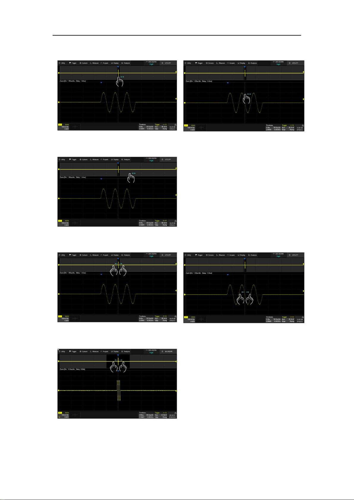
SDS5000X Series Digital Oscilloscope User Manual
79 / 2 3 6 W W W. S I G L E N T. C O M
by different gestures, as follows:
Adjust the horizontal position of the zoom area by dragging left and right in the zoom area
of the main window or waveform in Zoom window
Adjust the horizontal position of the waveform by dragging left and right in the gray area
of the main window
Adjust the horizontal scale of Zoom window by horizontal pinch and spread in the gray
area of the main window or in the Zoom window
Adjust the horizontal scale of main window by pinch and spread in the zoom area of the
main window
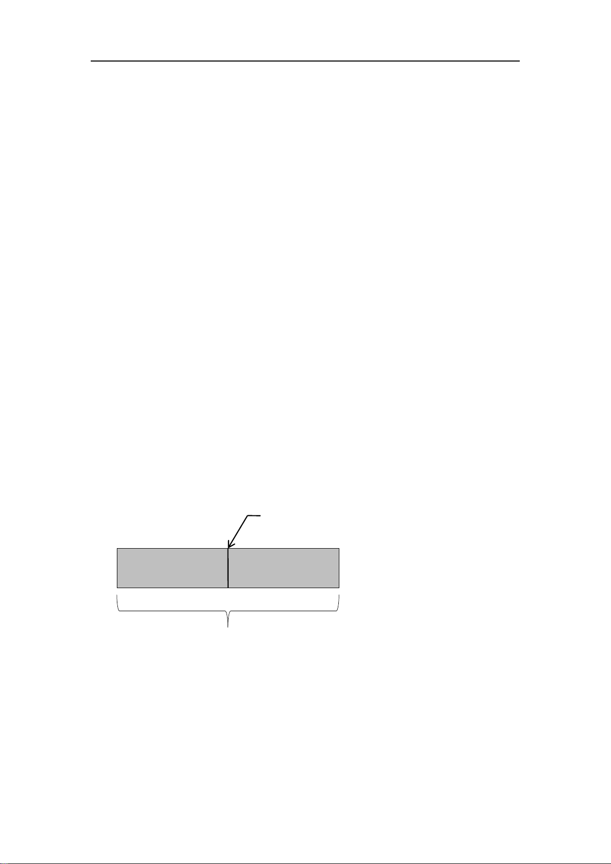
SDS5000X Series Digital Oscilloscope User Manual
80 / 2 3 6 W W W. S I G L E N T. C O M
15 Trigger
15.1 Overview
The oscilloscope only acquires waveforms of interest (i.e. the ones that satisfy
the trigger condition) and aligns all trigger events at the trigger position to form
a stable waveform display. The trigger is one of the most important features of
any oscilloscope, since we can only analyze a signal that we are able to
trigger in a reliable and stable manner.
The trigger position is movable on the display. The following diagram shows the
structure of the acquisition memory. The acquisition memory is divided into pre-
trigger and post-trigger buffers and the boundary between them is the trigger
position. Before the trigger event arrives, the oscilloscope fills the pre-trigger
buffer first, and then continuously updates it in FIFO mode until the trigger event
arrives. After the trigger event, the data fills the post-trigger buffer. When the
post-trigger buffer is full, an acquisition is completed.
Below are the definition of the states in the process of filling the acquisition
memory:
Arm: The pre-trigger buffer is not full, and the oscilloscope does not respond to
any trigger events.
Pre-trigger Buffer
Post-trigger Buffer
Trigger Event
Acquisition Memory
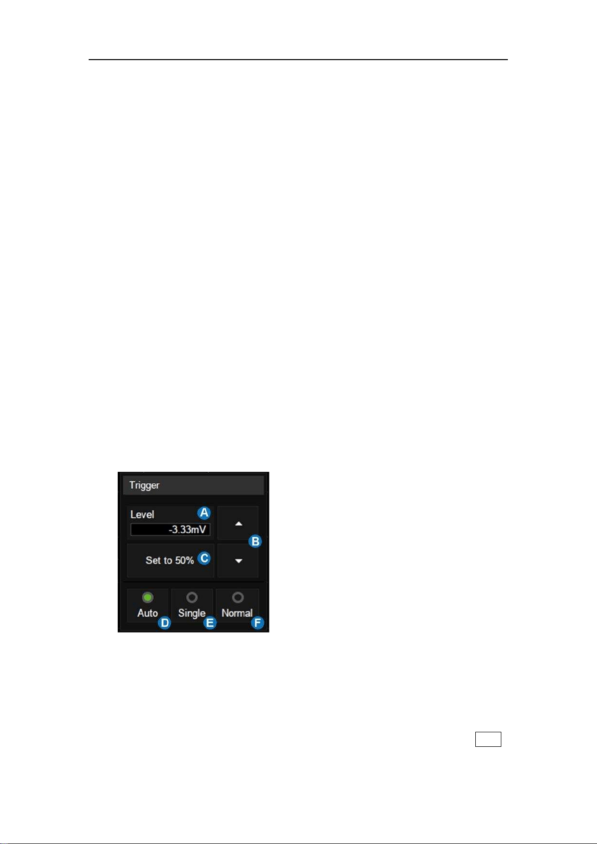
SDS5000X Series Digital Oscilloscope User Manual
81 / 2 3 6 W W W. S I G L E N T. C O M
Ready: The pre-trigger buffer is full, and the oscilloscope is waiting for the
trigger event.
Trig’d: A trigger event is detected and the oscilloscope starts to fill the post-
trigger buffer.
Trigger settings should be based on the features of the input signal. For
example, a sine wave with repeatable period can be triggered on the rising edge;
for capturing hazards in a combinational logic circuit, the pulse trigger can be
set. You need to have some knowledge of the signal-under-test to quickly
capture the desired waveform.
15.2 Trigger Setup
Touch the trigger descriptor box to display the quick menu of trigger settings.
The trigger setup dialog box is displayed on the right side of the screen.
A. Touch the level region and rotate the
Level knob on the front panel to
adjust trigger level; touch the region
again and the virtual keypad will be
available
B. ▲ to increase and ▼ to decrease
the trigger level
C. Set trigger level to the vertical center
of the waveform automatically
D. Set the trigger mode to "Auto", which
is equivalent to pressing the Auto
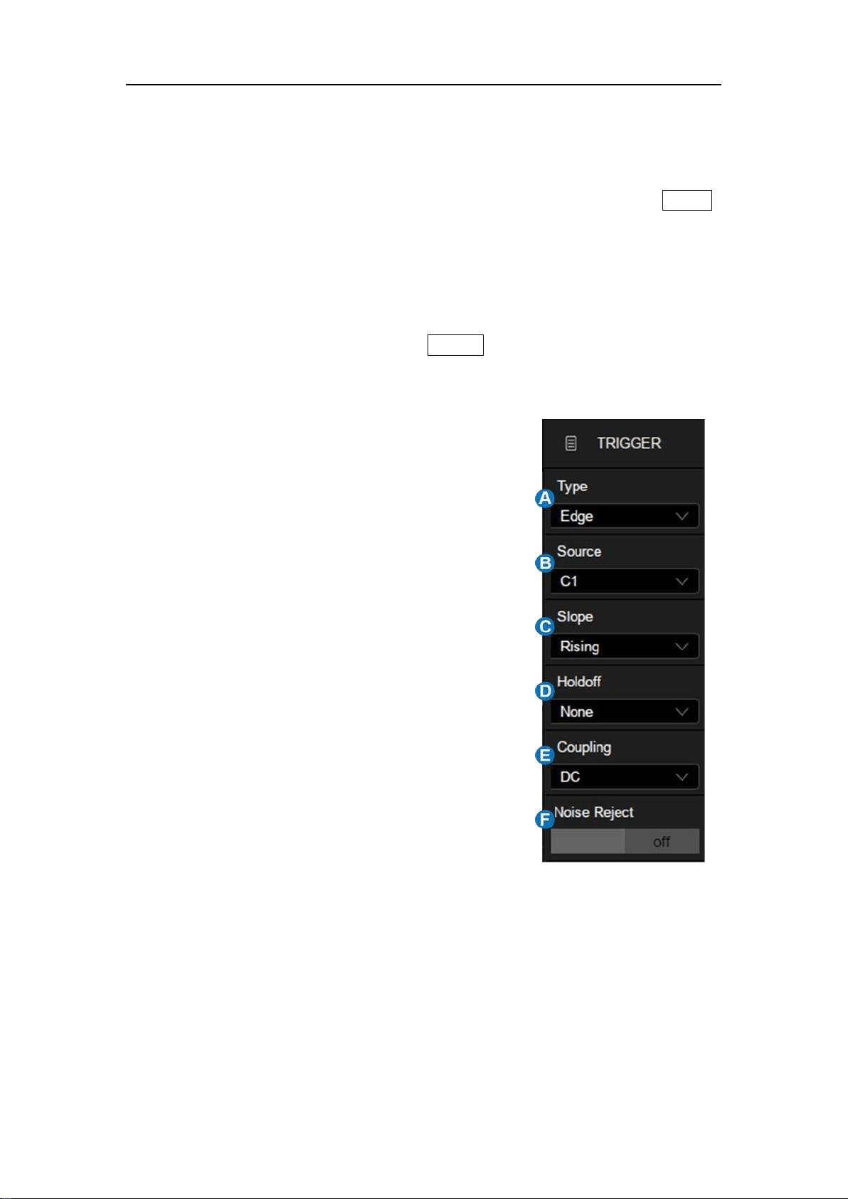
SDS5000X Series Digital Oscilloscope User Manual
82 / 2 3 6 W W W. S I G L E N T. C O M
button on the front panel
E. Set the trigger mode to "Single", which
is equivalent to pressing the Single
button on the front panel
F. Set the trigger mode to "Normal",
which is equivalent to pressing the
Normal button on the front panel
A. Select trigger type
B. Select the trigger source
C. Select the trigger slope (When the
trigger type is "Edge", "Slope" and
other specific types)
D. Set holdoff (None/Time/Events)
E. Set trigger coupling mode (DC/AC/LF
Reject/HF Reject)
F. Enable/disable Noise Rejection.
When Noise Reject is on, the trigger
hysteresis is increased, so the noise
immunity of the trigger circuit is better.
As a compromise, the trigger
sensitivity degrades
Trigger Related Label
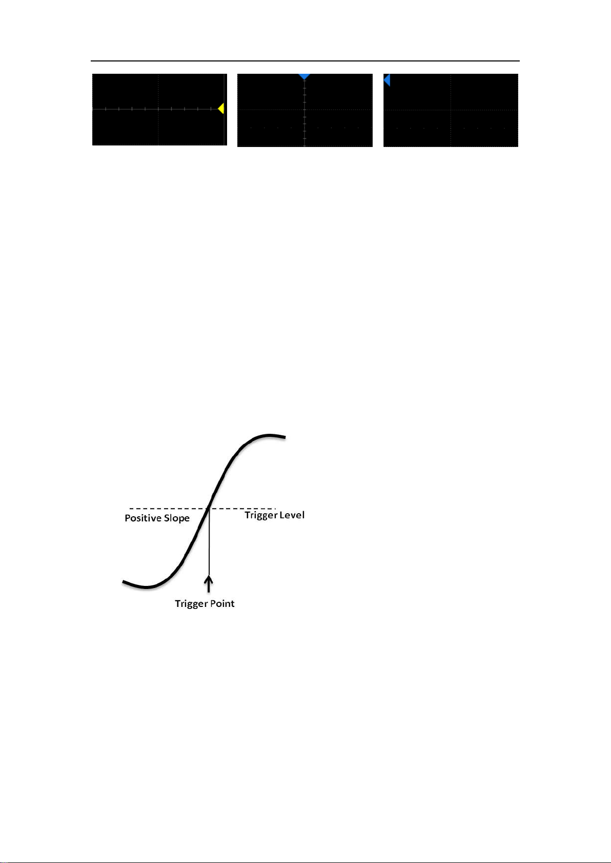
SDS5000X Series Digital Oscilloscope User Manual
83 / 2 3 6 W W W. S I G L E N T. C O M
Trigger level Indicator
Horizontal 0 position
Indicator
Horizontal 0 position(out of
screen) Indicator
15.3 Trigger Level
Both analog and digital triggers must have a correct trigger level value. The
oscilloscope judges whether a waveform satisfies the trigger condition when it
crosses the trigger level. If it does, the crossing time is the trigger position. In
the following figure, the trigger condition is set as rising edge. When the signal
with positive slope crosses the trigger level, the trigger condition is satisfied and
the time point the signal crosses the level is the trigger position.
In some special trigger, the system will automatically set the trigger level, such
as using AC Line as the trigger source.

SDS5000X Series Digital Oscilloscope User Manual
84 / 2 3 6 W W W. S I G L E N T. C O M
15.4 Trigger Mode
The trigger mode determines how the oscilloscope acquires waveforms.
Auto:An internal timer triggers the sweep after a preset timeout period if no
trigger has been found, so that the oscilloscope continuously updates the
display whether a trigger happens or not. Auto mode is suitable for unknown
signals or DC signals.
Note: In Auto mode, if the signal satisfies the trigger conditions but cannot
trigger the oscilloscope stably, it may be that interval between two trigger
events exceeds the timeout period. Try Normal mode in this case.
Normal:Triggers and acquisitions only occur when the trigger conditions are
met. Otherwise, the oscilloscope holds the last waveform on the display and
waits for the next trigger. Normal mode is suitable for acquiring:
Only events specified by the trigger settings
Rare events
Single : Captures and displays a single frame which satisfies the trigger
conditions, and then stops. The following trigger events are ignored until the
Single acquisition is restarted. Single mode is suitable for:
One-shot events or periodic signals, such as power-on\off waveforms
on a power rail
Rare events
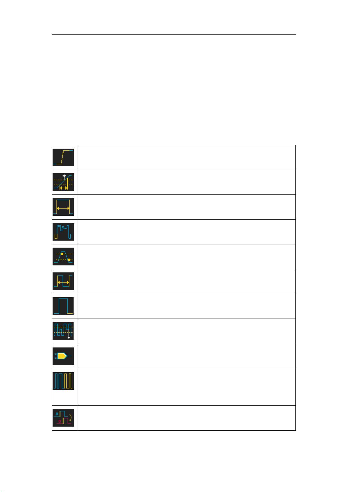
SDS5000X Series Digital Oscilloscope User Manual
85 / 2 3 6 W W W. S I G L E N T. C O M
15.5 Trigger Type
15.5.1 Overview
The trigger modes of the SDS5000X are digital designs. Compared with analog
trigger circuits, digital triggers can not only greatly optimize trigger precision,
trigger jitter, but also support multiple trigger types and complex trigger
conditions.
Edge -- Trigger on rising edge, falling edge or both
Slope -- Trigger when an edge crosses two thresholds which lie inside or
outside a selected time range
Pulse -- Trigger at the end of a pulse when the pulse width lies inside or
outside a selected time range
Video -- TV trigger on falling edge
Window -- Trigger when the signal leaves the widow region.
Interval -- Trigger on second edge when the time between the edges is
inside or outside a selected time range
Dropout -- Trigger when signal disappears for longer than Dropout value.
Runt -- Trigger when a pulse crosses the 1st threshold but not the 2nd
before re-crossing the 1
st
threshold again
Pattern -- Trigger when pattern condition transitions from false to true. All
inputs set to DC coupling
Serial -- Trigger on specified condition in a serial bus. See the chapter
"Noise Reject = On
Serial Trigger and Decode " for details.
Qualified -- Trigger with edge trigger setting only after the qualifying
condition is satisfied

SDS5000X Series Digital Oscilloscope User Manual
86 / 2 3 6 W W W. S I G L E N T. C O M
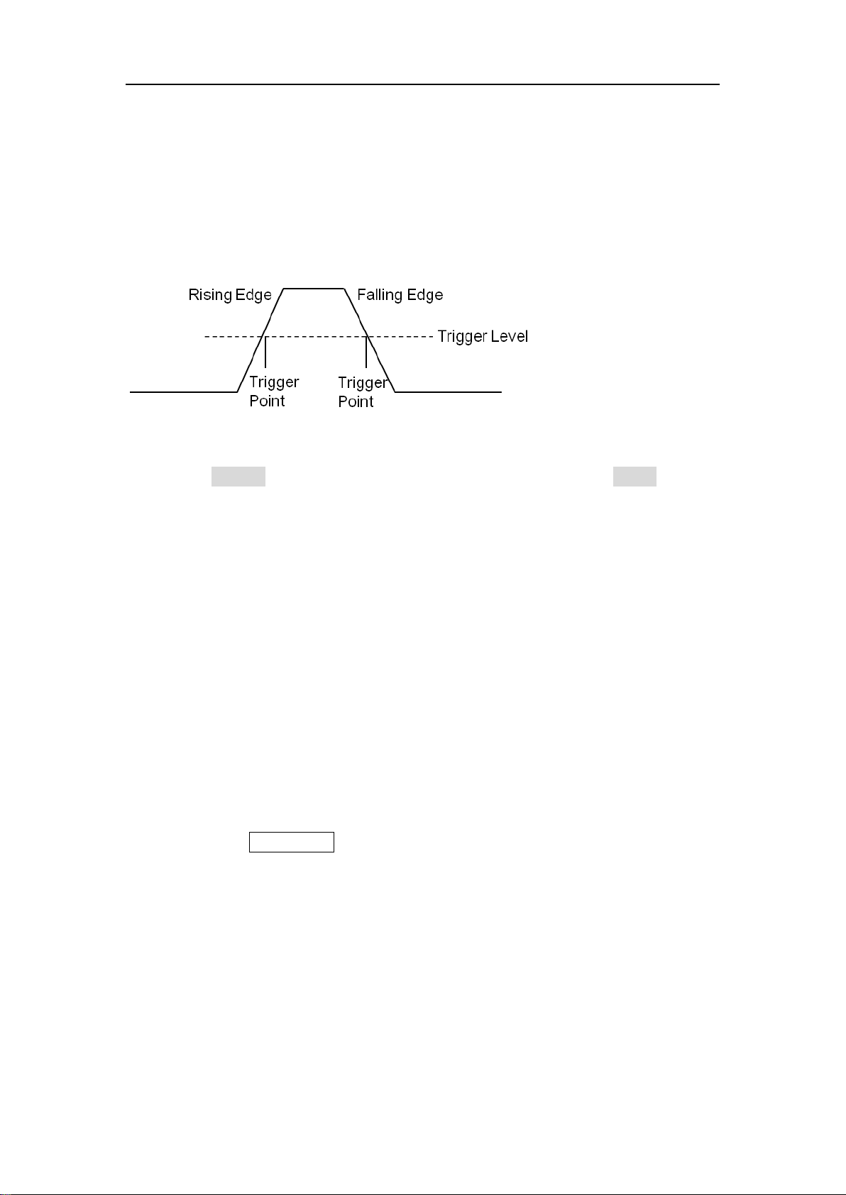
SDS5000X Series Digital Oscilloscope User Manual
87 / 2 3 6 W W W. S I G L E N T. C O M
15.5.2 Edge Trigger
Edge trigger distinguishes the trigger points by seeking the specified edge
(rising, falling, rising & falling) and trigger level. Trigger source and slope can
be set in the trigger dialog box.
Touch the Source area to select trigger source, and touch the Slope area to
select rising, falling or alter.
Rising -- Only trigger on the rising edge
Falling -- Only trigger on the falling edge
Alter -- Trigger on both rising edge and falling edge
Holdoff, coupling and noise reject can be set in edge trigger, see the sections
"Holdoff", "Trigger Coupling" and "Noise Reject" for details.
Note: Press the Auto Setup button, and the oscilloscope will set the trigger type
to Edge.
15.5.3 Slope Trigger
The slope trigger looks for a rising or falling transition from one level to another
level in the specified time range. For example, positive slope time is defined as
the time difference between the two crossing points of trigger level line A and B
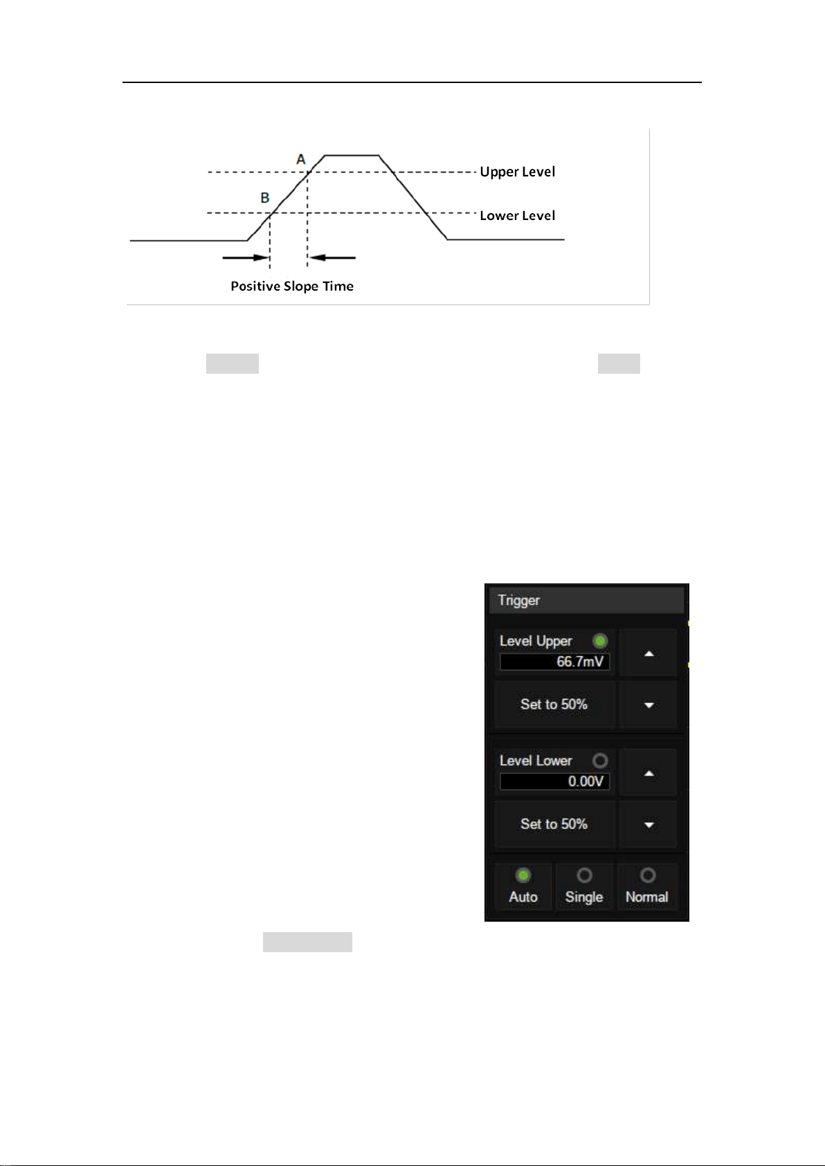
SDS5000X Series Digital Oscilloscope User Manual
88 / 2 3 6 W W W. S I G L E N T. C O M
with the positive edge as shown in the figure below.
Touch the Source area to select trigger source, and touch the Slope area to
select rising or falling.
Rising -- Only trigger on the positive slope
Falling -- Only trigger on the negative slope
Adjust Upper/Lower Level
The slope trigger requires upper and
lower trigger levels. When the trigger
type is slope trigger, touch the trigger
descriptor box, the pop-up quick menu
will show two levels.
The upper/lower level can be set in the
following two ways:
1. Touch the Level Upper area in the quick menu to select the upper level,
and then set the level value by the virtual keypad or the Level knob on
the front panel. To set the lower level is the similar.
2. Use the Level knob on the front panel directly to set the level value.

SDS5000X Series Digital Oscilloscope User Manual
89 / 2 3 6 W W W. S I G L E N T. C O M
Press the knob to switch between upper and lower level, and rotate it
to set the value.
The lower level should always be less than or equal to the upper level. In the
trigger descriptor box, the lower level is displayed.
Set Limit Range
Touch the Limit Range area in the trigger dialog box to select the time condition
and set the corresponding time in the Upper Value/Lower Value area.
Less than a time value(≤)-- Trigger when the positive or negative slope
time of the input signal is lower than the specified time value.
Great than a time value
(≥)-- Trigger when the positive or negative slope
time of the input signal is greater than the specified time value.
Within a range of time value
([--,--])-- Trigger when the positive or negative
slope time of the input signal is greater than the specified lower limit of time and
lower than the specified upper limit of time value.
Outside a range of time value
(--][--)-- Trigger when the positive or negative
slope time of the input signal is greater than the specified upper limit of time
and lower than the specified lower limit of time value.
Coupling and noise reject can be set in slope trigger, see the sections "Coupling”
and “Noise" for details.
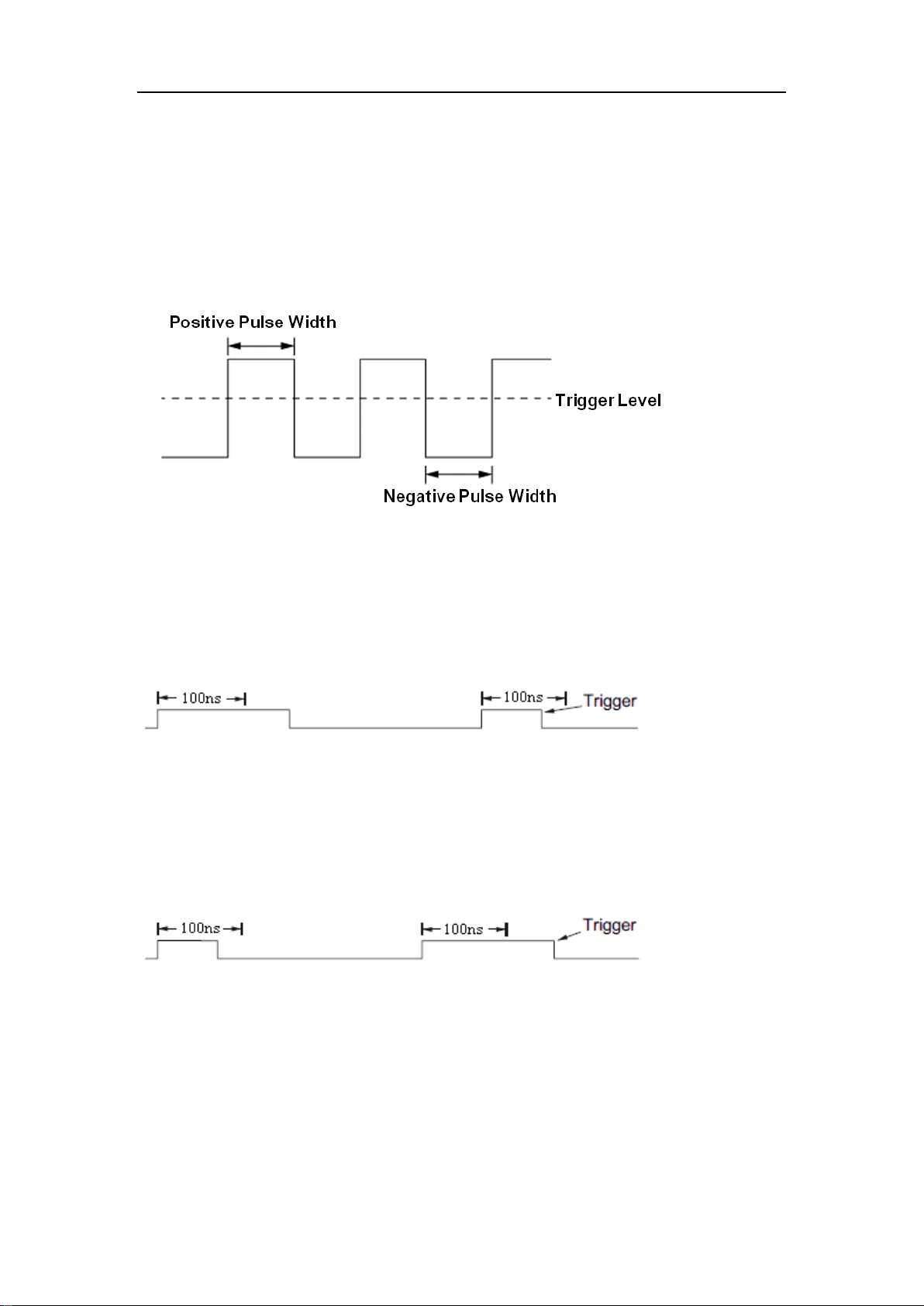
SDS5000X Series Digital Oscilloscope User Manual
90 / 2 3 6 W W W. S I G L E N T. C O M
15.5.4 Pulse Trigger
Trigger on a positive or negative pulse with a specified width. Trigger source,
polarity (positive, negative), limit range and time value can be set in the trigger
dialog box.
Less than a time value
(≤)-- Trigger when the positive or negative pulse
time of the input signal is lower than the specified time value. Below is an
example of trigger condition is set to positive pulse width < 100ns
Great than a time value
(≥)-- Trigger when the positive or negative pulse
time of the input signal is greater than the specified time value. Below is an
example of trigger condition is set to positive pulse width > 100ns
Within a range of time value
([--,--])-- Trigger when the positive or negative
pulse time of the input signal is greater than the specified lower limit of time and
lower than the specified upper limit of the time value. Below is an example of
trigger condition is set to 100 ns<positive pulse width<300 ns.

SDS5000X Series Digital Oscilloscope User Manual
91 / 2 3 6 W W W. S I G L E N T. C O M
Outside a range of time value
(--][--)-- trigger when the positive or negative
pulse time of the input signal is greater than the specified upper limit of time
and lower than the specified lower limit of the time value.
Coupling and noise reject can be set in pulse trigger, see the sections "Coupling”
and “Noise" for details.
15.5.5 Video Trigger
Video trigger can be used to capture the complicated waveforms of most
standard analog video signals. The trigger circuitry detects the vertical and
horizontal interval of the waveform and produces trigger based on the video
trigger settings you have selected. The SDS5000X supports standard video
signal for NTSC (National Television Standards Committee), PAL (Phase
Alternating Line), HDTV (High Definition Television) and a custom video signal
trigger.
Source, standard and synchronization mode can be set in video trigger dialog
box. When the synchronization mode is "Select", line and field can be specified.
Touch the Standard and select the video standard. The SDS5000X supports
the following video standards:
SDS5000X Series Digital Oscilloscope User Manual
92 / 2 3 6 W W W. S I G L E N T. C O M
TV Standard
Scan Type
Sync Pulse
NTSC
Interlaced
Bi-level
PAL
Interlaced
Bi-level
HDTV 720P/50
Progressive
Tri-level
HDTV 720P/60
Progressive
Tri-level
HDTV 1080P/50
Progressive
Tri-level
HDTV 1080P/60
Progressive
Tri-level
HDTV 1080i/50
Interlaced
Tri-level
HDTV 1080i/60
Interlaced
Tri-level
Custom
The table below shows the parameters of the custom video trigger:
Frame Rate
25 Hz, 30 Hz, 50 Hz,60
Hz
Of Lines
300 ~ 2000
Of Fields
1, 2, 4, 8
Interlace
1:1, 2:1, 4:1, 8:1
Trigger Position
Line
Field
(line value)/1(1:1)
1
(line value)/2 (2:1)
1, 2, 3, 4, 5, 6, 7, 8
(line value)/4 (4:1)
1, 2, 3, 4, 5, 6, 7, 8
(line value)/8 (8:1)
1, 2, 3, 4, 5, 6, 7, 8
Line value: The number of lines set in the Of Lines (300 ~ 2000).
In the custom video trigger type, the corresponding "Of Fields" varies with the
selection of the “Interlace” ratio. Therefore, the number of fields selected and
the number of lines corresponding to each field can also be varied. If the "Of
SDS5000X Series Digital Oscilloscope User Manual
93 / 2 3 6 W W W. S I G L E N T. C O M
Lines" is set to 800, the correct relationship between them is as follows:
Of Lines
Interlace
Of Fields
Trigger Line
Trigger Field
800
1:1
1
800
1
800
2:1
1/2/4/8
400
1/1~2/1~4/1~8
800
4:1
1/2/4/8
200
1/1~2/1~4/1~8
800
8:1
1/2/4/8
100
1/1~2/1~4/1~8
Set the video trigger for video signal
Touch Sync for trigger mode selection, video trigger mode has "Any" and
"Select" options. In "Any" mode, the video signal can be triggered on any line
that meets the conditions. In "Select" mode, the signal can be triggered by a
specified field and a specified line.
For progressive scanning signals (e.g. 720p/50, 720p/60, 1080p/50, 1080p/60),
only the specified line can be selected to trigger when the synchronization mode
is “Select”.
For interlaced scanning signals (such as NTSC, PAL, 1080i/50, 1080i/60,
Custom), when the synchronization mode is "Select", the specified line and the
specified field can be selected to trigger.
The following table shows the corresponding relations between line and field
for all video standards (except for Custom)
Standard
Field 1
Field 2
NTSC
1 to 263
1 to 262

SDS5000X Series Digital Oscilloscope User Manual
94 / 2 3 6 W W W. S I G L E N T. C O M
PAL
1 to 313
1 to 312
HDTV 720P/50、720P/60
1 to 750
HDTV 1080P/50、1080P/60
1 to 1125
HDTV 1080i/50、1080i/60
1 to 563
1 to 562
To gain familiarization with the video trigger, try these two examples:
Trigger on specific line of video (NTSC standard)
Use “Custom” to trigger video signals
Trigger on a Specific Line of Video
Video trigger requires that any analog channel can be used as the trigger
source with a synchronization amplitude greater than 1/2 grid. The example
below sets to trigger on Field 1, Line 22 using the NTSC video standard.
1. Press the Setup button on the front panel to open the trigger menu.
2. In the trigger menu, touch Type, select "Video".
3. Touch the Source and select CH1 as the trigger source.
4. Touch the Standard and select the "NTSC".
5. Touch the Sync and select the "Select" to make the Field and Line
optional, then select "1" in the "Field", and set the "Line" to "22" by
using the universal knob or the virtual keypad.
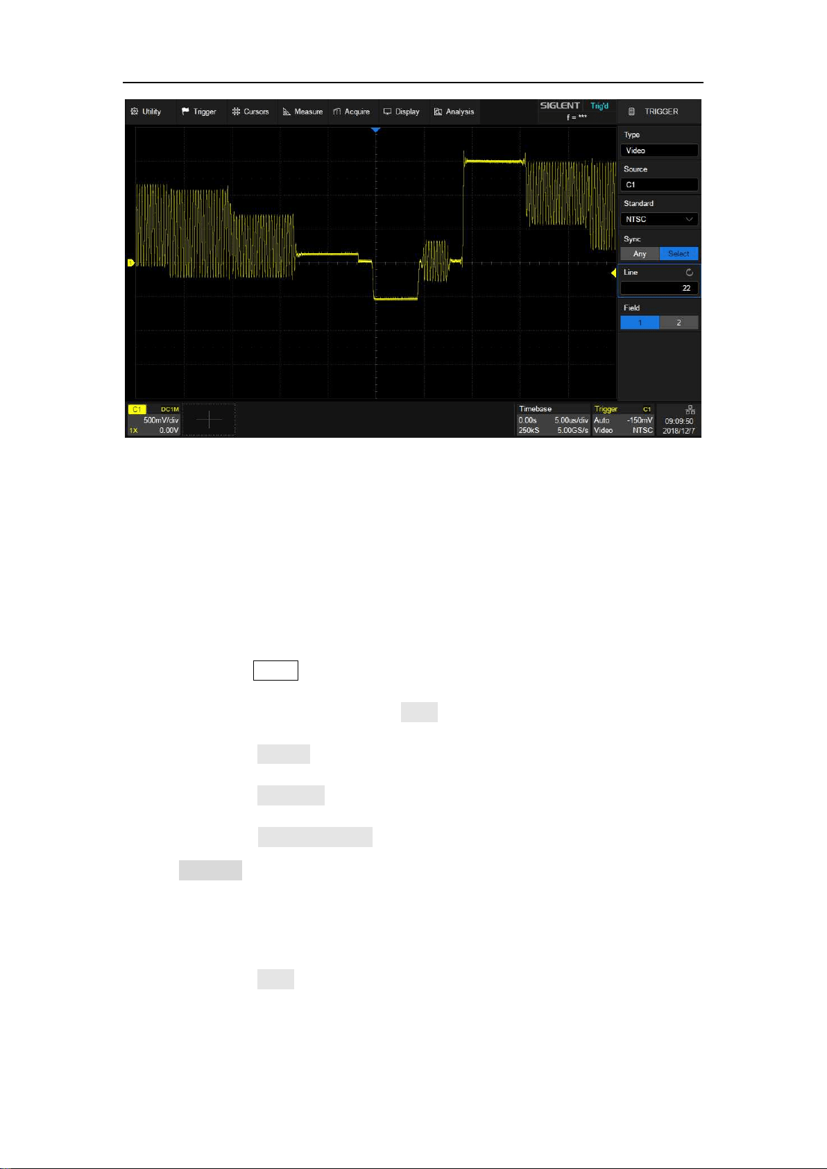
SDS5000X Series Digital Oscilloscope User Manual
95 / 2 3 6 W W W. S I G L E N T. C O M
Trigger on a Specific Line of Video (NTSC)
Use "Custom" to Trigger Video Signals
Custom video trigger supports video signals with frame rates of 25, 30, 50 and
60 Hz respectively, and the specified row is within the range of 300 to 2000.
The following describes how to trigger a "Custom" video signal.
1. Press the Setup button on the front panel to open the trigger menu.
2. In the trigger menu, touch the Type, select the "Video".
3. Touch the Source and select CH1 as the trigger source.
4. Touch the Standard and select the "Custom".
5. Touch the Custom Setting to open the custom setting menu, touch the
Interlace to select the required interlace ratio (assuming that the
interlace ratio is 8:1). Then set the frame rate, select the number of lines
and the number of fields.
6. Touch the Sync to select the synchronization mode for the input signal:
a) Select the "Any" mode, and the signal can be triggered on any line
that meets the trigger condition.
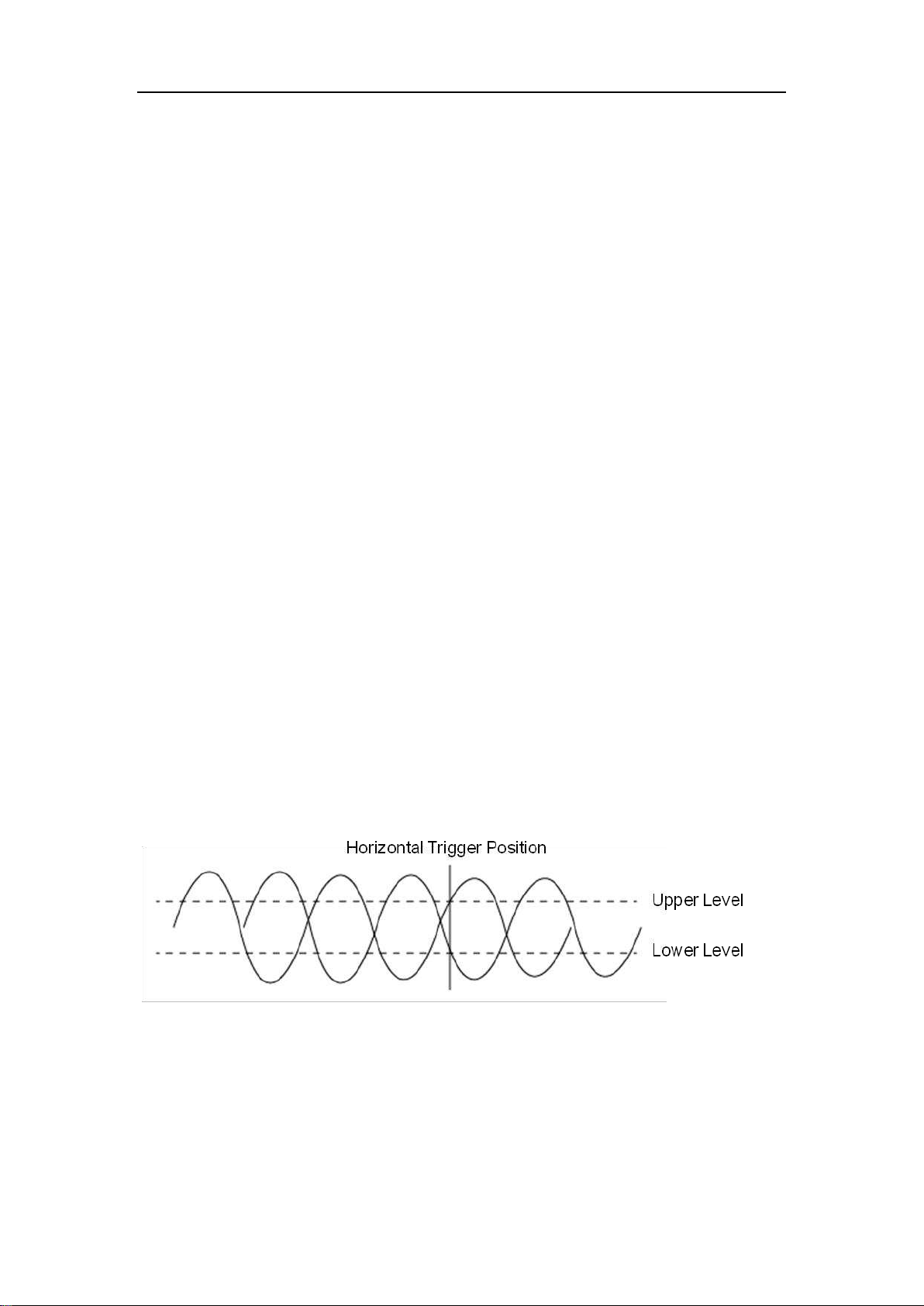
SDS5000X Series Digital Oscilloscope User Manual
96 / 2 3 6 W W W. S I G L E N T. C O M
b) Select the "Select" mode, then set the specified line and the
specified field to trigger the signal. Assuming that the "Field" is set
to 8, you can select any field from 1 to 8, and each field can choose
any line from 1 to 100.
15.5.6 Window Trigger
Window trigger is similar to edge trigger, except that it provides an upper and a
lower trigger level. The instrument triggers when the input signal passes
through the upper level or the lower level.
There are two kinds of window types: Absolute and Relative. They have
different trigger level adjustment methods. Under the Absolute window type, the
lower and the upper trigger levels can be adjusted separately. Relative window
provides adjustment for the Center value to set the window center and a the
Delta value to set the window range. In this mode, the lower and the upper
trigger levels always move together.
If the lower and the upper trigger levels are both within the waveform
amplitude range, the oscilloscope will trigger on both rising and falling
edges.
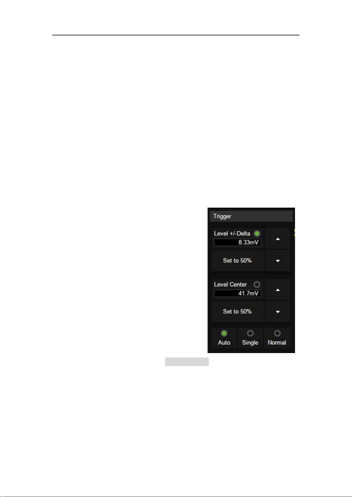
SDS5000X Series Digital Oscilloscope User Manual
97 / 2 3 6 W W W. S I G L E N T. C O M
If the upper trigger level is within the waveform amplitude range while
the lower trigger level is out of the waveform amplitude range, the
oscilloscope will trigger on the rising edge only.
If the lower trigger level is within the waveform amplitude range while
the upper trigger level is out of the waveform amplitude range, the
oscilloscope will trigger on the falling edge only.
To set window trigger via the Absolute window type
Refer to "Adjust Upper/Lower Level" in the section "Slope Trigger".
To set window trigger via the Relative window type
When the window trigger type is set to
"Relative", touch the trigger descriptor
box. The pop-up menu will show two
user defined parameters: "Level +/-
Delta" and "Level Center".
The above two parameters can be set
in the following two ways:
1. Select the parameter in the Level +/-Delta area of the quick menu, then
set the parameter value by the virtual keypad, or the Level knob on the
front panel. To set the center level is the similar.
2. Directly use the Level knob on the front panel. Press the knob to switch
between “Level +/-Delta" and "Center Level", and rotate it to set values.
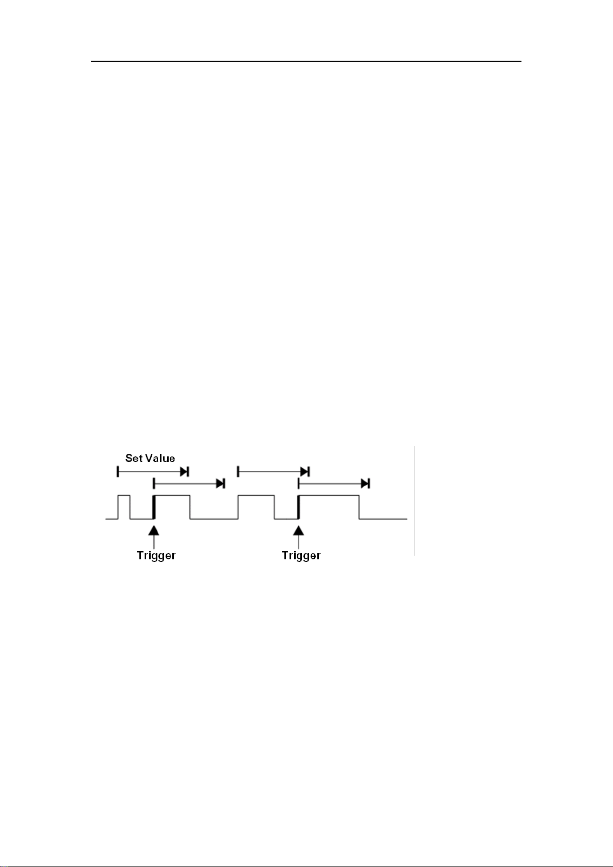
SDS5000X Series Digital Oscilloscope User Manual
98 / 2 3 6 W W W. S I G L E N T. C O M
Note: "Level +/-Delta” represents half of the actual window area. For example,
when the value is 200 mV, it actually represents a range of ± 200 mV, which is
a 400 mV window.
Coupling and noise reject can be set when using the window trigger, see the
sections "Coupling”, “Noise" for details.
15.5.7 Interval Trigger
Trigger when the time difference between the neighboring rising or falling edges
meets the time limit condition.
When the trigger condition is set as an interval between two neighboring rising
edges and it is less than the set time value, the trigger diagram is as follows:
Trigger source, slope (rising, falling), limit range and time value can be set in
the trigger dialog box. Coupling and noise reject can be set in the interval trigger,
see the sections "Coupling” and “Noise" for details
15.5.8 Dropout Trigger
Dropout trigger includes two types: Edge and state.
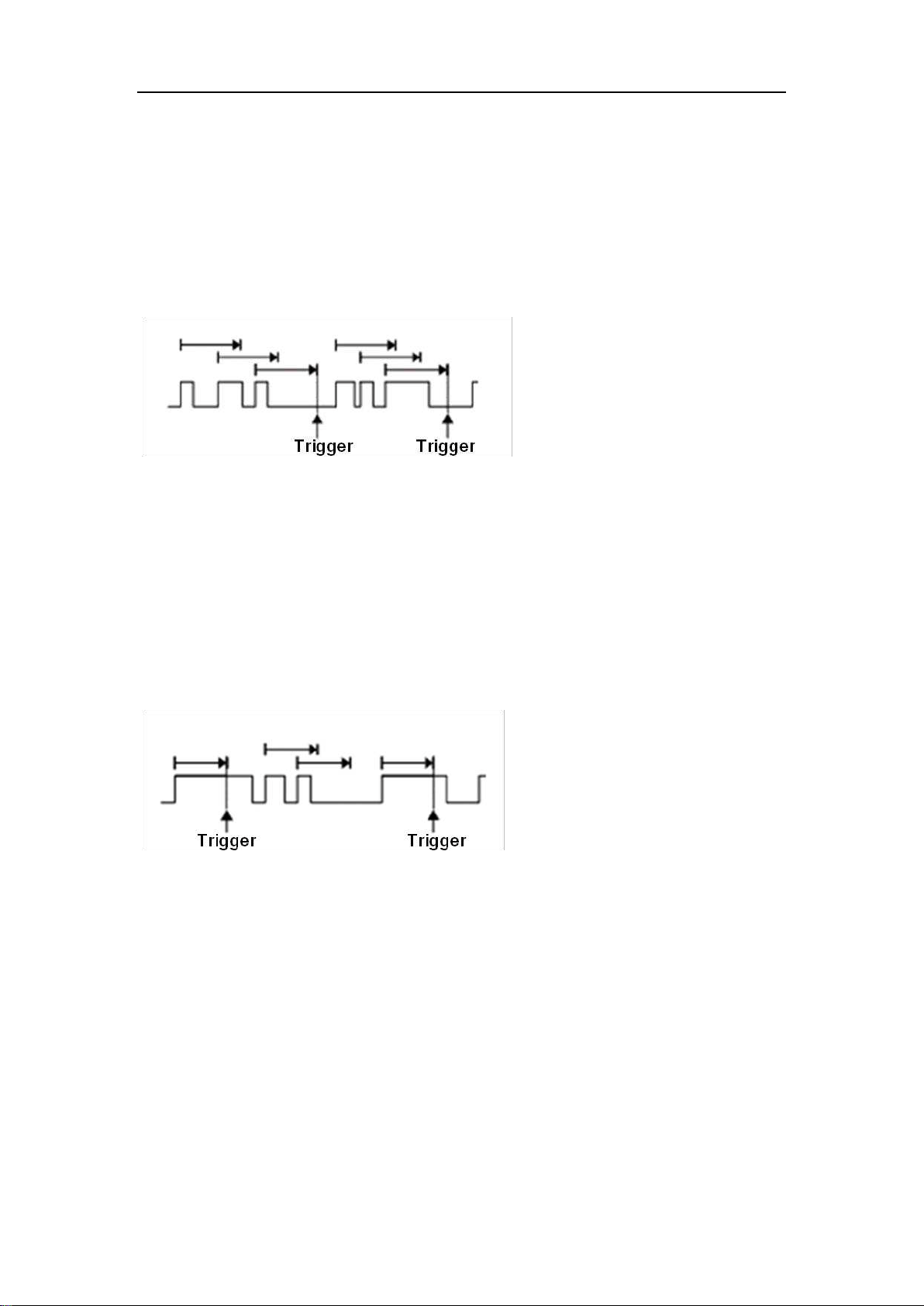
SDS5000X Series Digital Oscilloscope User Manual
99 / 2 3 6 W W W. S I G L E N T. C O M
Edge
Trigger when the time interval (△T) from when the rising edge (or falling edge)
of the input signal passes through the trigger level to when the neighboring
rising edge (or falling edge) passes through the trigger level is greater than the
set time, as shown in the figure below:
State
Trigger when the time interval (△T) from when the rising edge (or falling edge)
of the input signal passes through the trigger level to when the neighboring
falling edge (or rising edge) passes through the trigger level is greater than the
set time, as shown in the figure below:
Trigger source, slope (rising, falling), dropout type and time value can be set in
the trigger dialog box. Coupling and noise reject can be set in dropout trigger,
see the section “Coupling”, “Noise” for details
SDS5000X Series Digital Oscilloscope User Manual
100 / 236 W W W. S I G L E N T. C O M
15.5.9 Runt Trigger
Runt trigger looks for pulses that cross one threshold but not another as shown
in the figure below:
A positive runt pulse across through the low level but not the high level.
A negative runt pulse across through the high level but not the low level.
SDS5000X Series Digital Oscilloscope User Manual
101 / 236 W W W. S I G L E N T. C O M
15.5.10 Pattern Trigger
The Pattern trigger identifies a trigger condition by looking for a specified pattern.
The SDS5000X provides 4 patterns: logical AND, OR, NAND and NOR
combination of the channels. Each channel can set to "Low", "High" or "Don't
Care". If all channels are set to "Don’t Care", the oscilloscope will not trigger.
Logic (AND, OR, NAND, NOR), source, limit range and time value can be set
in the trigger dialog box. When the logic is "OR" or "NAND", the setting of time
limit is invalid.
Source Setting
Touch the Source Setting area to recall the following dialog box and set up for
each channel separately. Each channel can be set to "Low", "High" or "Don't
Care". The threshold can be determined by setting the Level Value.
When digital channels are turned on, the logic state of the digital channel can
also be set in the source setting dialog box.
SDS5000X Series Digital Oscilloscope User Manual
102 / 236 W W W. S I G L E N T. C O M
Logical setting of analog channel
Logical setting of digital channel
Limit Range
When the logic is "AND" or "NOR", the time limit condition is available. This
setting is particularly useful to filter the hazard signals of combinational logic.
When the logic is "OR" or "NAND", the time limit setting is not supported.
15.5.11 Qualified Trigger
Qualified trigger is an edge trigger after a user defined qualified condition is
satisfied. So a qualified trigger has two sources; one is the source of the edge
trigger, the other is the qualified source.
The qualified types include “State”, “State with Delay”, “Edge” and “Edge with
Delay”. When the type is “State”, the oscilloscope triggers on the first edge
when the qualified source is in the specified state (High or Low). When the
type is “State with Delay”, a time limit condition is also available.
SDS5000X Series Digital Oscilloscope User Manual
103 / 236 W W W. S I G L E N T. C O M
Qualified
Source
Edge
Trigger
Source
Trigger
Position
Qualified State = High
Edge = Rising
When the type is “Edge”, the oscilloscope triggers at the first edge after the
specified edge (Rising or Falling) of the qualified source; when the type is “Edge
with Delay”, time limit condition is available.
Qualified
Source
Edge
Trigger
Source
Trigger
Position
Qualified Edge = Rising
Edge = Rising
Touch the Qualified Setting region to set the qualified source and threshold;
Touch the Edge Setting region to set the edge trigger source, threshold and
slope.

SDS5000X Series Digital Oscilloscope User Manual
104 / 236 W W W. S I G L E N T. C O M
15.6 Trigger Source
The trigger sources supported by each trigger type are different. See the table
below for details:
Trigger Type
C1~C4
EXT, EXT/5
AC Line
D0~D15
Edge
√
√
√
√
Slope
√
×
×
×
Pulse
√
×
×
√
Video
√
×
×
×
Window
√
×
×
×
Interval
√
×
×
√
Dropout
√
×
×
√
Runt
√
×
×
×
Pattern
√
×
×
√
Serial
√
×
×
√
Qualified
√
×
×
√
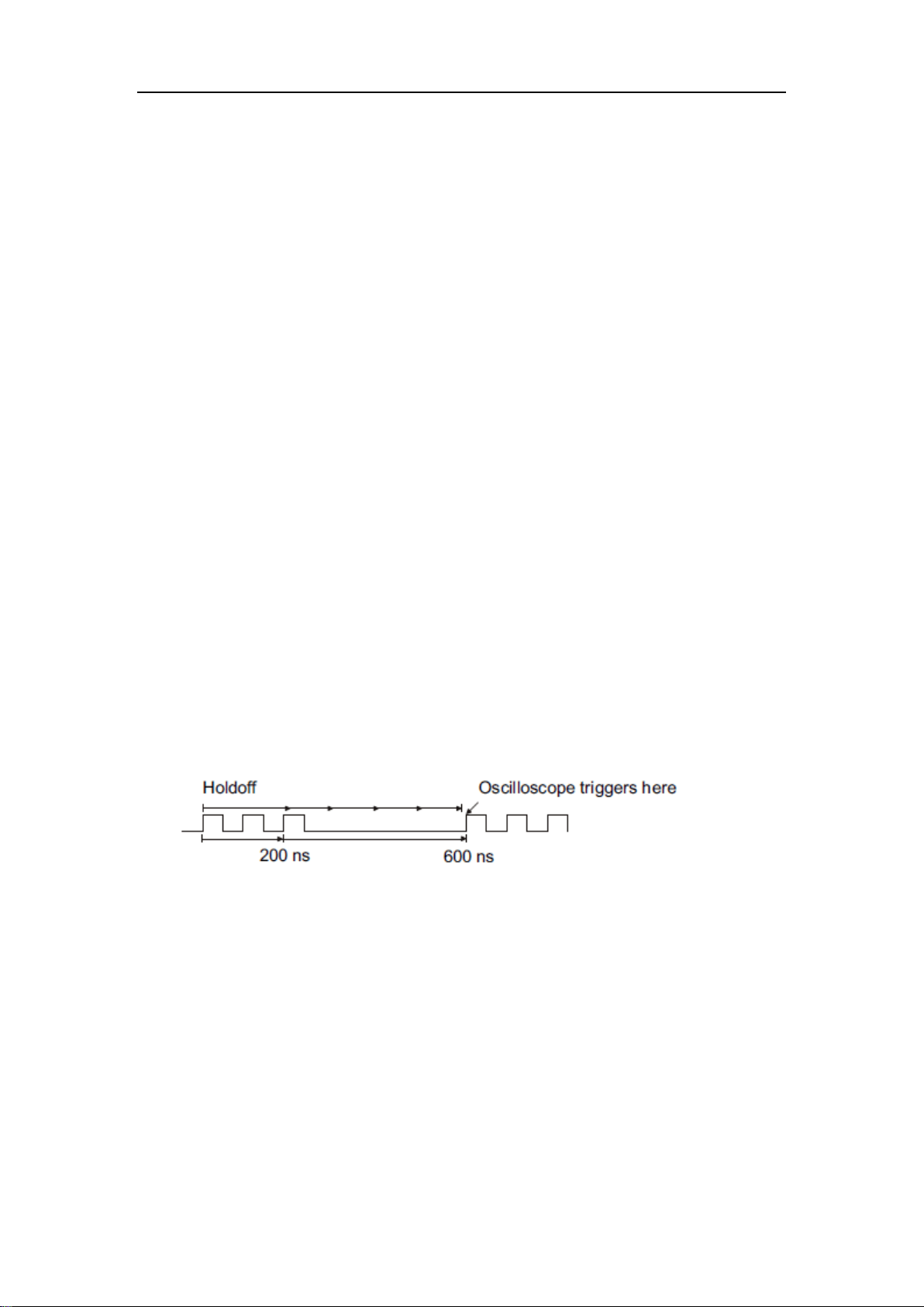
SDS5000X Series Digital Oscilloscope User Manual
105 / 236 W W W. S I G L E N T. C O M
15.7 Holdoff
Holdoff is an additional condition for triggers and can be used to stabilize the
triggering of complex waveforms (such as a pulse series). It can be set to a time
or number of events.
Holdoff by Time
Holdoff time is the amount of time that the oscilloscope waits before re-arming
the trigger circuitry. The oscilloscope will not trigger until the holdoff time expires.
Use the holdoff to trigger on repetitive waveforms that have multiple edges (or
other events) between waveform repetitions. You can also use holdoff to trigger
on the first edge of a burst when you know the minimum time between bursts.
For example, to achieve a stable trigger on the repetitive pulses shown in the
figure below, set the holdoff time (t) to 200ns<t<600ns.
Holdoff by Event
Holdoff event is the amount of events that the oscilloscope counts before re-
arming the trigger circuitry. The oscilloscope will not trigger until the counter
tracking holdoff events reaches the set value. In the following figure, the holdoff
event is set to 3, and the signal is triggered on the fourth edge.
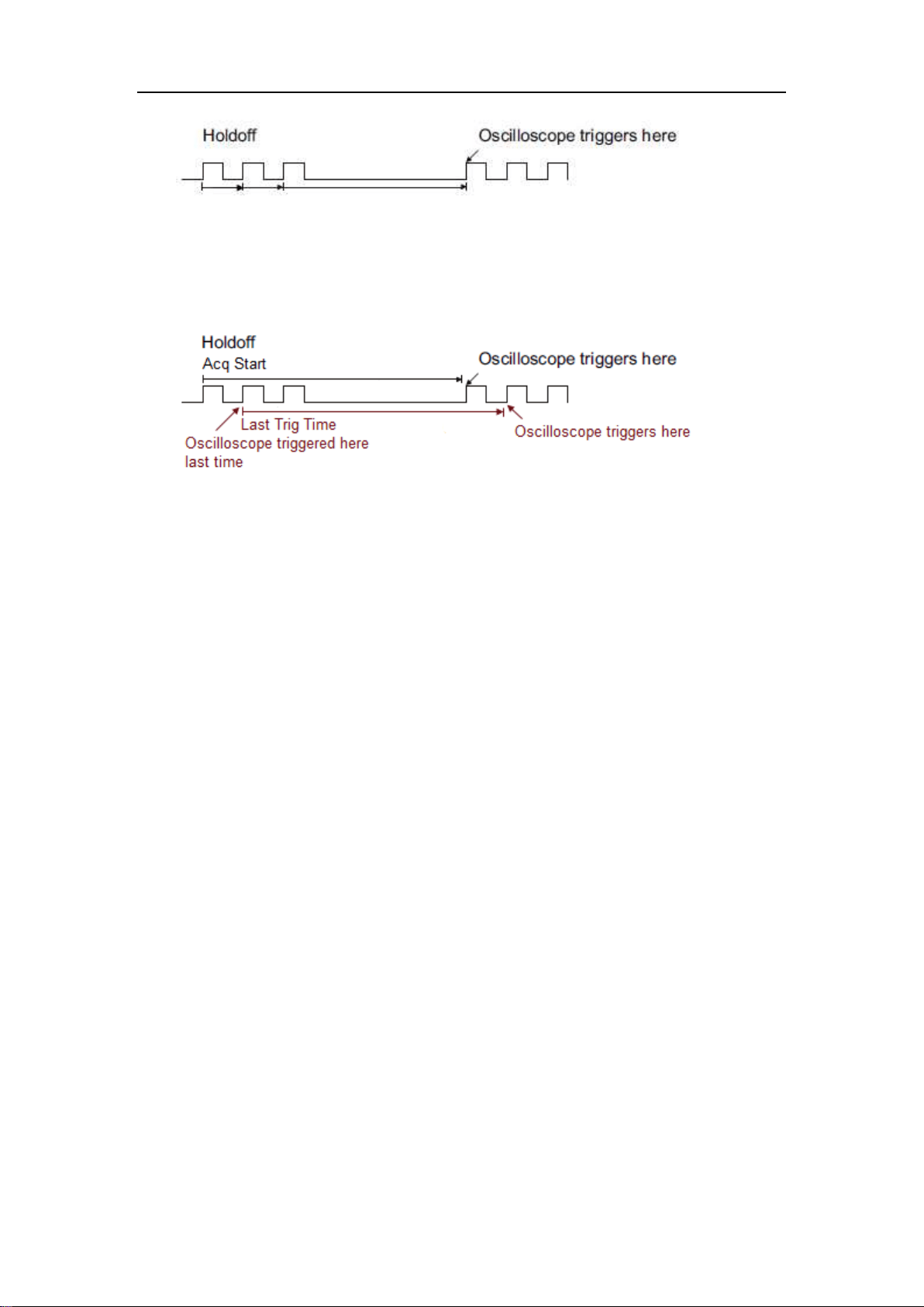
SDS5000X Series Digital Oscilloscope User Manual
106 / 236 W W W. S I G L E N T. C O M
Parameter Start Holdoff On defines the initial position of holdoff.
Acq Start -- The initial position of holdoff is the first time point satisfying the
trigger condition. In the example above, each holdoff starts from the first rising
edge of the pulse sequence.
Last Trig Time -- The initial position of holdoff is the time of the last trigger. In
the example above, the last trigger position is at the second rising edge of the
pulse sequence and the second holdoff starts from that point.

SDS5000X Series Digital Oscilloscope User Manual
107 / 236 W W W. S I G L E N T. C O M
15.8 Trigger Coupling
The coupling setting of trigger is only valid when the trigger source is C1~C4,
EXT or EXT/5.
DC: All of the signal’s frequency components are coupled to the trigger
circuit for high frequency bursts or where the use of AC coupling would shift
the effective trigger level.
AC: The signal is capacitively coupled. DC levels are rejected. See the
datasheet for details of the cut-off frequency.
HFR: Signals are DC coupled to the trigger circuit and a low-pass filter
network attenuates high frequencies (used for triggering on low
frequencies). See the datasheet for details of the cut-off frequency.
LFR: The signal is coupled through a capacitive high-pass filter network,
DC is rejected and low frequencies are attenuated. For stable triggering on
medium to high frequency signals. See the datasheet for details of the cut-
off frequency.
15.9 Noise Reject
Noise Reject adds additional hysteresis to the trigger circuitry. By increasing
the trigger hysteresis, the noise immunity becomes better but the trigger
sensitivity degrades.
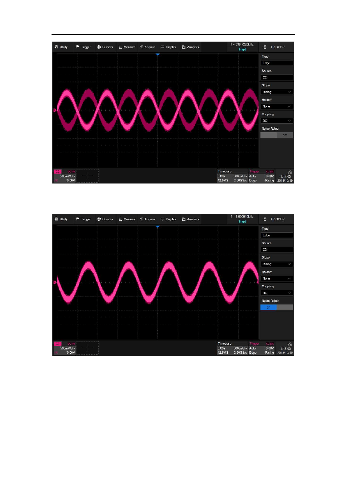
SDS5000X Series Digital Oscilloscope User Manual
108 / 236 W W W. S I G L E N T. C O M
Noise Reject = Off
Noise Reject = On
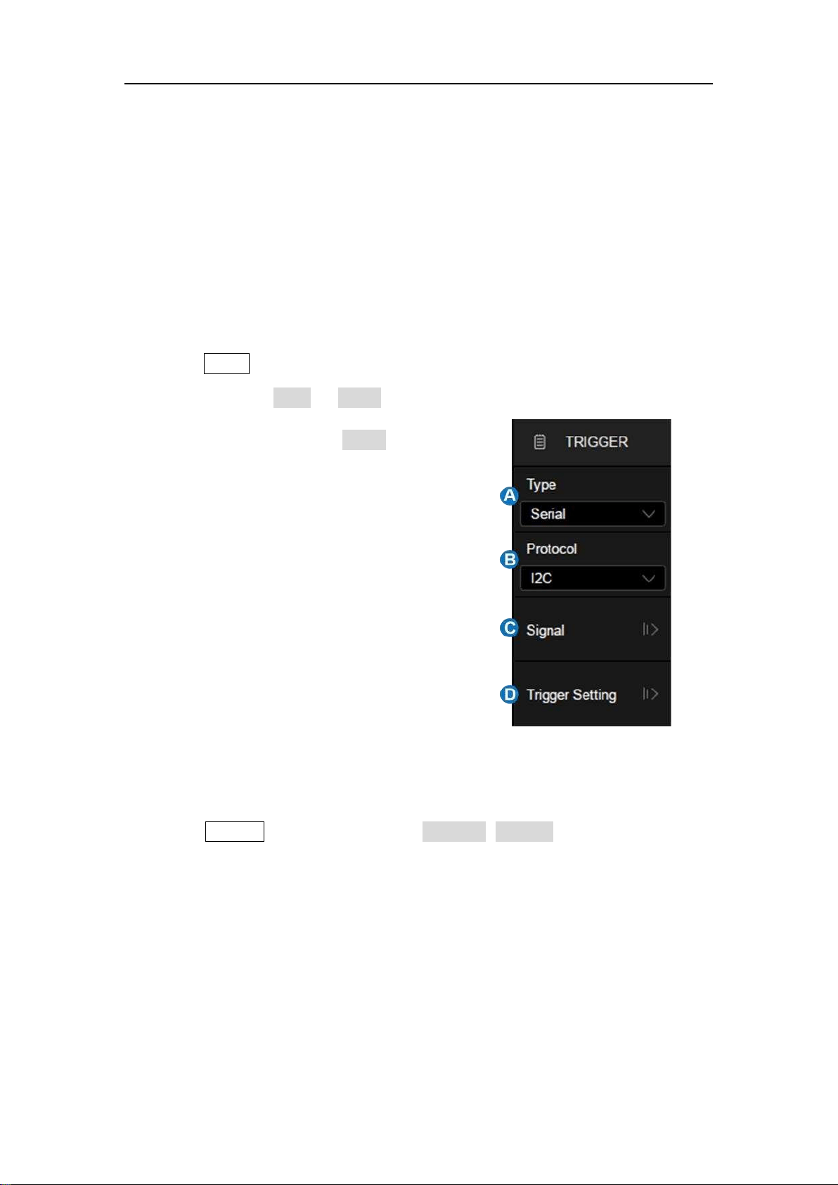
SDS5000X Series Digital Oscilloscope User Manual
109 / 236 W W W. S I G L E N T. C O M
16 Serial Trigger and Decode
16.1 Overview
The SDS5000X supports serial bus trigger and decode on the following serial
bus protocols: I2C, SPI, UART, CAN, and LIN.
Press the Setup button on the front panel or touch the trigger descriptor box,
and then select the Type as Serial in the trigger dialog box to set serial trigger:
A. Select the type as Serial
B. Select the serial bus protocol
C. Set the signal, including the mapping
relation between channels and bus
signals, and the thresholds
D. Trigger setting
Press the Decode button or touch the Analysis>Decode to turn on the serial
decode dialog box:
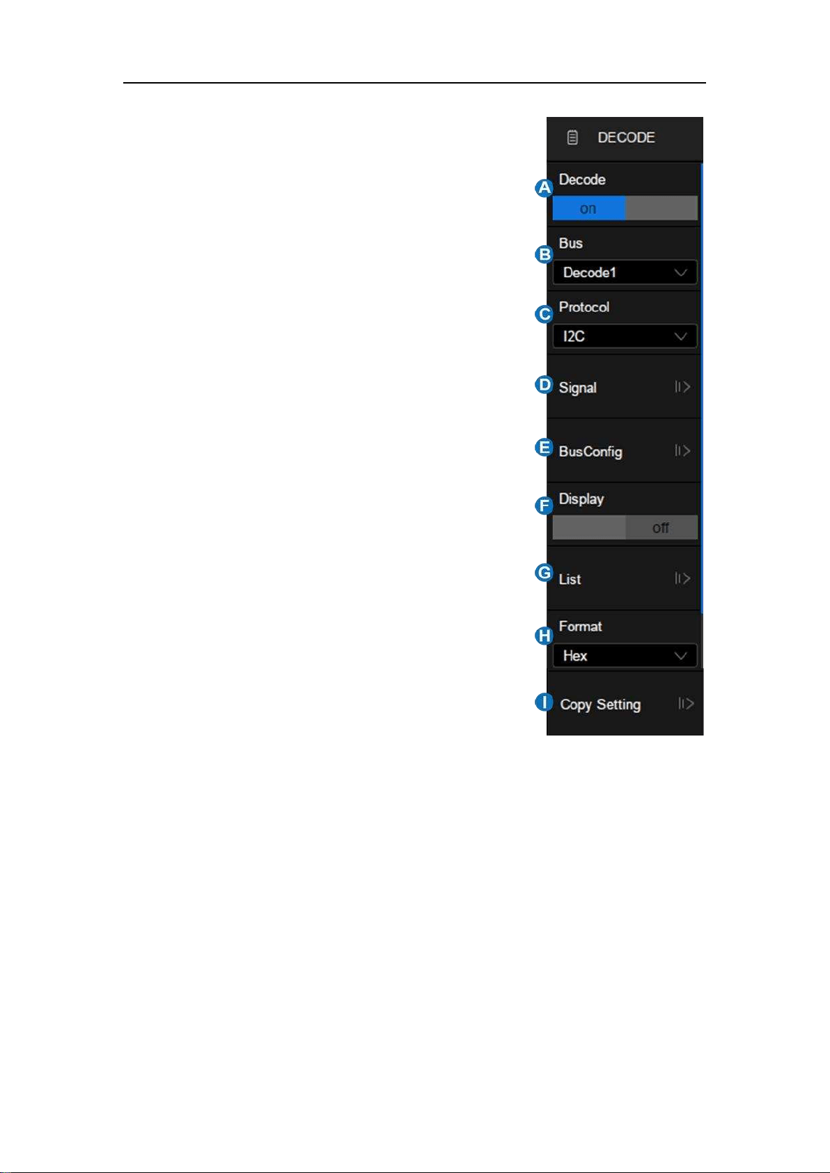
SDS5000X Series Digital Oscilloscope User Manual
11 0 / 2 3 6 W W W. S I G L E N T. C O M
A. Turn on/off serial decode function
B. Select the bus to set, Decode1 and
Decode2
C. Select the serial bus protocol
D. Touch to set the signal, including the
mapping relation between channels and
bus signals, and the thresholds. This is
similar with the signal setting of serial
trigger.
E. Configure the bus
F. Display the bus or not
G. Set the list of decode result
H. Set the display format of the decode results
(Hex, Decimal, Binary or ASCII)
I. Synchronize the settings between serial
trigger and decode
Below are detailed descriptions of trigger and decode steps for each protocol.
I2C Trigger and Serial Decode
SPI Trigger and Serial Decode
UART Trigger and Serial Decode
CAN Trigger and Serial Decode
LIN Trigger and Serial Decode
错误!未找到引用源。
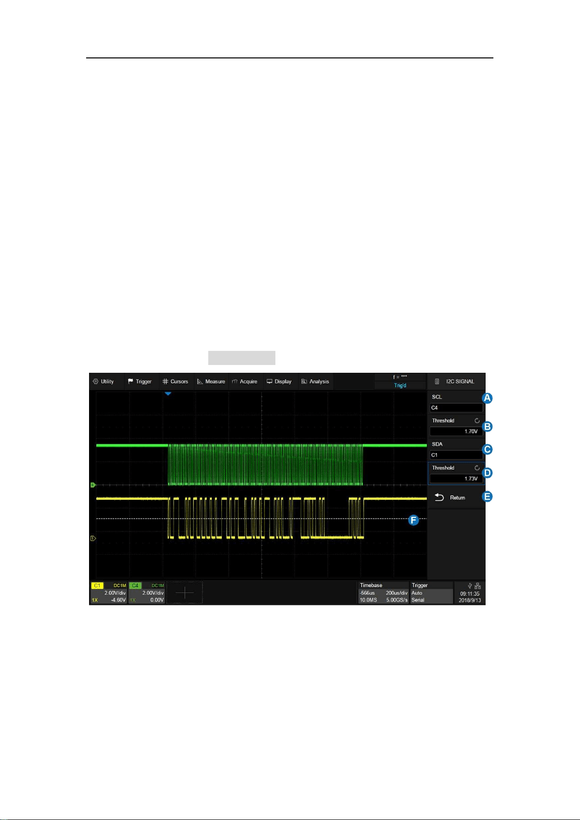
SDS5000X Series Digital Oscilloscope User Manual
111 / 2 3 6 W W W. S I G L E N T. C O M
16.2 I2C Trigger and Serial Decode
This section covers triggering and decoding I2C signals. Please read the
following for more details: "I2C Signal Settings", "I2C Trigger" and "I2C Serial
Decode".
16.2.1 I2C Signal Settings
Connect the serial data signal (SDA) and serial clock signal (SCL) to the
oscilloscope, set the mapping relation between channels and signals and then
set the threshold level of each signal. The signal settings of decode and trigger
are independent. If you want to synchronize the settings between decode and
trigger, please perform Copy Setting in the decode dialog box.
A. Set the source of SCL. In the example above, SCL is connected to C4.
B. Set the threshold level of SCL. It is 1.7 V for the LVTTL signal in this
example.
C. Set the source of SDA. In the example above, SDA is connected to C1.
D. Set the threshold level of the SDA channel.
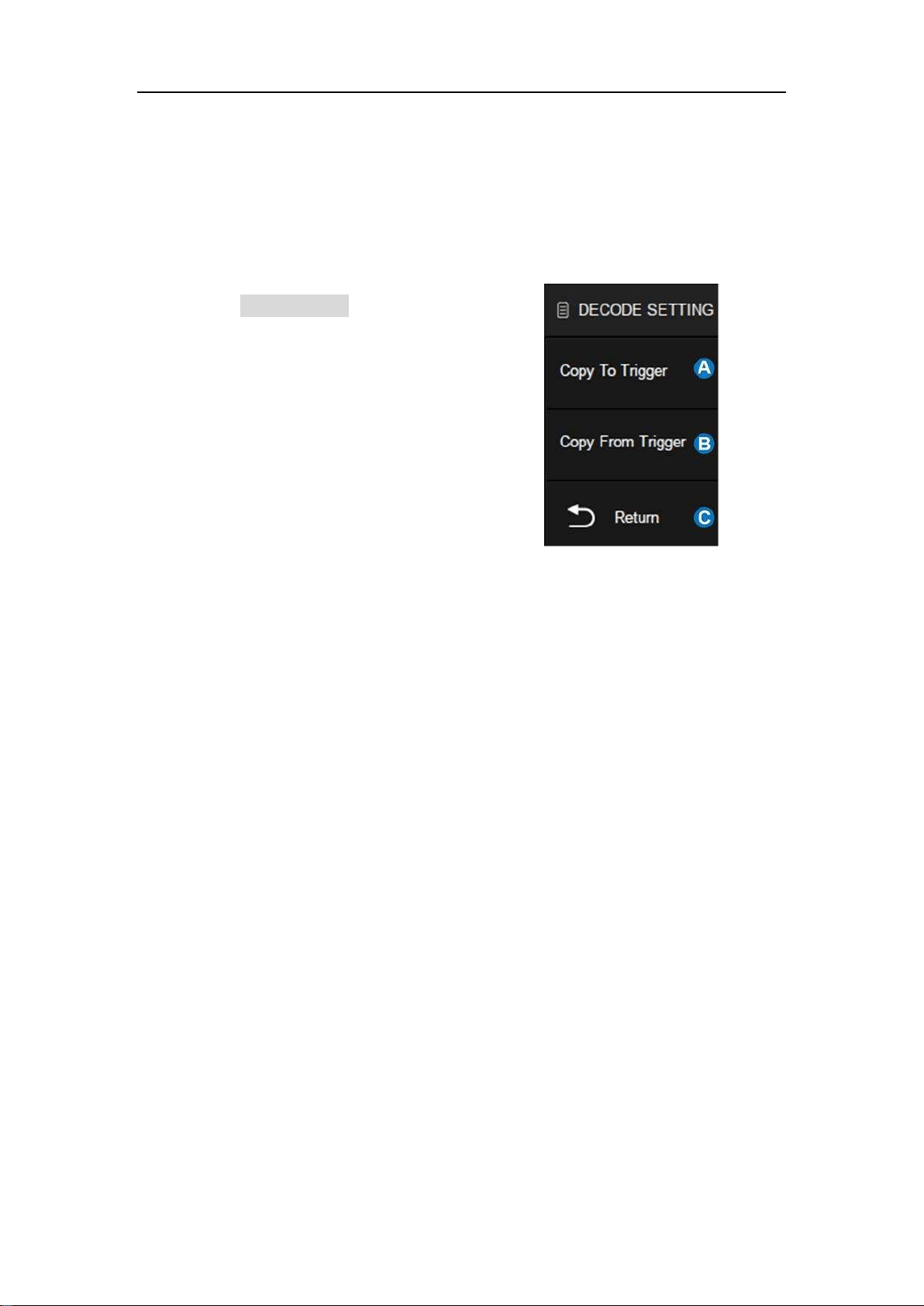
SDS5000X Series Digital Oscilloscope User Manual
11 2 / 2 3 6 W W W. S I G L E N T. C O M
E. Return to previous menu.
F. Threshold level line. It only appears when adjusting the threshold level.
Copy Setting
Touch the Copy Setting in the decode dialog
box to synchronize the settings between
trigger and decode.
A. Copy the decode settings to trigger
B. Copy the trigger settings to decode
C. Return to previous menu.
Note: The synchronization is not automatic. If the settings at one place change,
a copy operation is necessary to re-synchronize.
16.2.2 I2C Trigger
When the protocol is set to I2C, the following trigger conditions can be set: Start,
Stop, Restart, No Ack, EEPROM, or an R/W frame with specific device address
and data value.
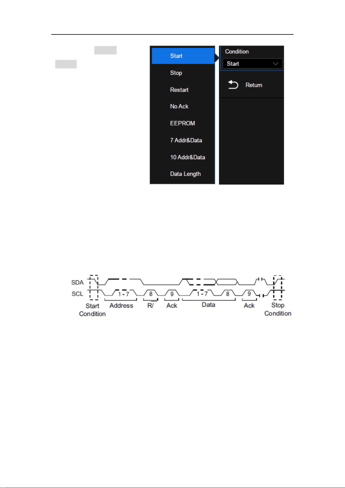
SDS5000X Series Digital Oscilloscope User Manual
11 3 / 2 3 6 W W W. S I G L E N T. C O M
Touch Trigger
Setting in the I2C
trigger dialog box to
select the trigger
condition:
Start — The oscilloscope will be triggered when the SDA line transitions from
high to low while the SCL is high.
Stop — The oscilloscope will be triggered when the SDA line transitions from
low to high while the SCL is high.
Restart— The oscilloscope will be triggered when another “Start” occurs before
a “Stop".
No Ack— The oscilloscope will be triggered when the SDA line is high during
any SCL’s ACK bit.
SDS5000X Series Digital Oscilloscope User Manual
11 4 / 2 3 6 W W W. S I G L E N T. C O M
EEPROM — The trigger searches for EEPROM
control byte value 1010xxx on the SDA bus. And
there is a Read bit and an ACK bit behind
EEPROM. Set the data value and compare type
according to Data1 and Limit Range. If EEPROM’s
data is greater than (less than, equal to) Data1, the
oscilloscope will be triggered at the edge of ACK
bit behind Data byte. It’s unnecessary that the
Data byte musts follow the EEPROM.
7 Address&Data — the oscilloscope will be triggered on read or write frame in
7-bit address mode.
Frame (Start: 7-bit address: R/W: Ack) — Data1 and Data2 are set to “0xXX”.
If all bits match, then trigger on the Ack bit followed by the R/W bit.
Frame (Start: 7-bit address: R/W: Ack: Data: Ack: Data2) — If all bits match,
then trigger on the Ack bit followed by the Data2.
SDS5000X Series Digital Oscilloscope User Manual
11 5 / 236 W W W. S I G L E N T. C O M
10 Address&Data — If all bits match, then trigger on the Ack bit followed by
the Data.
Frame (Start: Address 1st byte: R/W: Ack: Address 2nd byte: Ack: Data)
SDS5000X Series Digital Oscilloscope User Manual
11 6 / 2 3 6 W W W. S I G L E N T. C O M
If you set the trigger condition to 7 address&data or
10 address&data:
Address can be selected in the hexadecimal
range of 0x00 to 0x7F (7-bit) or 0x3FF (10-bit). If
the address is selected as "0xXX (7-bit address)"
or "0xXXX (10-bit address)", the address is
ignored. It will always trigger on the Ack bit
followed by the address.
Data1 and Data2 can be selected in the
hexadecimal range of 0x00 to 0xFF. If the data is
selected as "0xXX", the data is ignored. It will
always trigger on the Ack bit followed by the
address.
R/W Bit can be specified as Write, Read or Don't
Care.
Data Length — The data length range is 1 to 12 bytes. When the SDA data
length is equal to the value of Date Length and address length is the same as
set value, the oscilloscope will be triggered.
Touch the Address Length to select "7-bits" or "10-bits" to match the
address of the input signal.
Touch the Data Length and turn the universal knob or by virtual keypad to
set the data length to match the data length of input signal.
SDS5000X Series Digital Oscilloscope User Manual
11 7 / 2 3 6 W W W. S I G L E N T. C O M
16.2.3 I2C Serial Decode
Layout of the touchscreen display when I2C decode enabled is as follows:
A. Waveform display area, shows the original waveforms of the bus
signals
B. Bus display, shows the decode result of the bus. At most two buses
can be decoded at the same time. Touch Display of the dialog box to
turn on or off selected bus, and touch Format to select the display type
of decode result (Binary, Decimal, Hex or ASCII)
C. List display area. Decode result of multiple frames can be displayed in
the list, in which each row shows the time label and decode result of a
frame. Touch List to set the parameters of list.
D. Decode dialog box
SDS5000X Series Digital Oscilloscope User Manual
11 8 / 2 3 6 W W W. S I G L E N T. C O M
Bus
The address value is displayed at the beginning of a frame. The write
address is displayed in green, and read address in yellow.
W/R bit is represented by (W) and (R), following the address value.
The "~A" after a data or address bits indicates no acknowledgement.
For example, DB
~A.
The data value is displayed in white.
indicates there is not enough space on the display to show the
complete content of a frame, and some content is hidden.
List
TIME — The horizontal offset of the current data frame head relative
to the trigger position.
Address — Address value. For example, "0x2AB" means that address
= 2AB with acknowledgement.
R/W — Read address or write address.
DATA — Data bytes.

SDS5000X Series Digital Oscilloscope User Manual
11 9 / 2 3 6 W W W. S I G L E N T. C O M
Configuration
There is only one item Include R/W Bit in the configuration of the I2C decode.
When it is disabled, the address is represented separately from the R/W bit,
and when it is enabled, the R/W bit is represented together with the address.
For example, the address 0x4E: Write: Ack, is displayed as "0x4E (W)" when
the R/W bit is not included, and is displayed as "0x9C" when the R/W bit is
included.

SDS5000X Series Digital Oscilloscope User Manual
120 / 236 W W W. S I G L E N T. C O M
16.3 SPI Trigger and Serial Decode
The following sections describe SPI trigger and decode: "SPI Signal Settings",
"SPI Trigger" and "SPI Serial Decode".
16.3.1 SPI Signal Settings
Connect the CLK, MOSI, MISO and CS signals to the oscilloscope and set the
mapping relation between channels and signals. Then set the threshold level of
each signal. The process of specifying the source and threshold is similar to
"I2C Signal Settings".
CLK
In addition to specifying the source and the threshold level, for CLK signal it is
also necessary to specify the Edge Select.
Rising– Data latched on rising edge of the clock.
Falling– Data latched on falling edge of the clock.
The user can select the edge according to the actual phase relationship
between the clock and data of the SPI bus. Referring to the following figure,
when the falling edge of the clock is aligned with the data, the rising edge is
selected to latch the data. When the rising edge of the clock is aligned with the
data, the falling edge is selected to latch the data.
SDS5000X Series Digital Oscilloscope User Manual
121 / 236 W W W. S I G L E N T. C O M
CS
The CS signal should be set to correct CS Type, including CS, ~CS and Clock
Timeout.
CS – Active high.
~CS – Active low.
Clock Timeout– It is not necessary to specify the source and threshold level
for the CS signal. The only parameter for the CS signal is the timeout Limit,
which is the minimum time that the clock signal must be held idle for before
the oscilloscope acquires valid data. This setting is suitable for case where
CS signal is not connected, or the number of oscilloscope channels is
insufficient (such as two-channel oscilloscopes).
The method of copying settings is the same as I2C signal settings. See "I2C
Signal Settings" for details.
SDS5000X Series Digital Oscilloscope User Manual
122 / 236 W W W. S I G L E N T. C O M
16.3.2 SPI Trigger
The trigger condition for SPI trigger is mainly about
data. Touch Trigger Setting in the dialog box to set data:
A. Trigger Type: MISO or MOSI
B. Data Length: 4~96 bits
C. Set to trigger on the specified data value.
Touch Data Value twice, and enter the value by
the virtual keypad, or touch All Same to set all
bits to 0, 1 or ignored ("X")
D. Set the bit order to MSB or LSB
E. Return to previous menu
16.3.3 SPI Serial Decode
The configuration of SPI decoding is similar to I2C.
In the BusConfig menu, Data Length (4-32 bit) and Bit Order (LSB or MSB) are
configurable.

SDS5000X Series Digital Oscilloscope User Manual
123 / 236 W W W. S I G L E N T. C O M
16.4 UART Trigger and Serial Decode
The following sections cover trigger and decoding UART signals: "UART Signal
Settings", "UART Trigger" and "UART Serial Decode".
16.4.1 UART Signal Settings
Connect the RX and TX signals to the oscilloscope, set the mapping relation
between channels and signals, and then set the threshold level of each signal.
The process of specifying the source and threshold is similar to "I2C Signal
Settings".
In the BusConfig menu of trigger or decode, the following parameters are
available:
SDS5000X Series Digital Oscilloscope User Manual
124 / 236 W W W. S I G L E N T. C O M
A. Touch to select the baud rate:
600,1200,2400,4800,9600,19200,38400,5760
0,115200 or Custom
B. Data Length: 5~8bit
C. Parity Check: Odd Even or None
D. Select the number of stop bits
E. Set the idle level
F. Set the bit order
G. Return to previous menu
The method of copying settings is the same as I2C signal settings. See "I2C
Signal Settings" for details.
16.4.2 UART Trigger
Touch Trigger Setting in the dialog box to set the trigger condition:
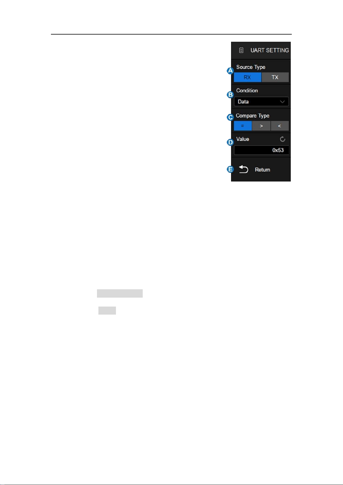
SDS5000X Series Digital Oscilloscope User Manual
125 / 236 W W W. S I G L E N T. C O M
A. Source Type: RX or TX
B. Trigger Condition: Start, Stop, Data or Error
C. When the "trigger condition" is Data, set the
compare type to: =, >, <
D. When the "trigger condition" is Data, set the
data value
E. Return to previous menu
Trigger Condition
Start — The oscilloscope triggers when the start bit appears on the RX/TX.
Stop — The oscilloscope triggers when the stop bits appear on the RX/TX.
It always triggers on the first stop bit.
Data — Trigger on data
Touch Compare Type to select "=", ">" or "<".
Touch Value to set the data value by the universal knob or virtual
keypad. The range of data value is 0x00 to 0xff.
Error — The oscilloscope performs parity check on the data according to
the parity type set by the user, and triggers if the check value is incorrect.
16.4.3 UART Serial Decode
The set of SPI decode is similar to that of I2C decode.

SDS5000X Series Digital Oscilloscope User Manual
126 / 236 W W W. S I G L E N T. C O M
16.5 CAN Trigger and Serial Decode
The following section covers triggering and decoding CAN signals: "CAN
Signal Settings", "CAN Trigger" and "CAN Serial Decode".
16.5.1 CAN Signal Settings
Connect the CAN_H and CAN_L signals to the oscilloscope, set the mapping
relation between channels and signals, and then set the threshold level of each
signal. The process of specifying the source and threshold is similar to "I2C
Signal Settings".
In BusConfig menu of trigger and decode, baud rate can be set to: 5 kb/s, 10
kb/s, 20 kb/s, 50 kb/s, 100 kb/s, 125 kb/s, 250 kb/s, 500 kb/s, 800 kb/s, 1 Mb/s
or Custom.
The method of copying settings is the same as I2C signal settings. See "I2C
Signal Settings" for details.
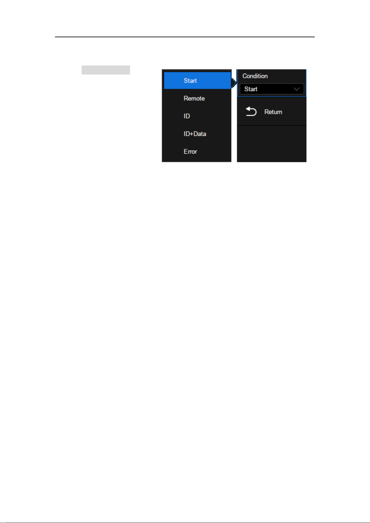
SDS5000X Series Digital Oscilloscope User Manual
127 / 236 W W W. S I G L E N T. C O M
16.5.2 CAN Trigger
Touch Trigger Setting in the
CAN trigger dialog box to
set the trigger condition:
Start — The oscilloscope triggers at the beginning of the frame.
Remote — The oscilloscope triggers on a remote frame with a specified
ID. ID, ID Bits (11-bit or 29-bit) and Curr ID Byte (1st, 2nd, 3rd, or 4th byte)
can be set. Curr ID Byte is used to specify the byte to be adjusted when
using the universal knob.
ID — The oscilloscope triggers on the data frame that matches the
specified ID. ID, ID Bits (11-bit or 29-bit), and Curr ID Byte (1st, 2nd, 3rd, or
4th byte) can be set.
ID+Data — The oscilloscope triggers on the data frame that matches the
specified ID and data. ID, ID Bits (11-bit or 29-bit), Curr ID Byte (1st, 2nd,
3rd, or 4th byte), Data1 and Data2 can be set.
Error — The oscilloscope triggers on the error frame.
16.5.3 CAN Serial Decode
The set of SPI decode is similar to that of I2C decoding.
On the bus:
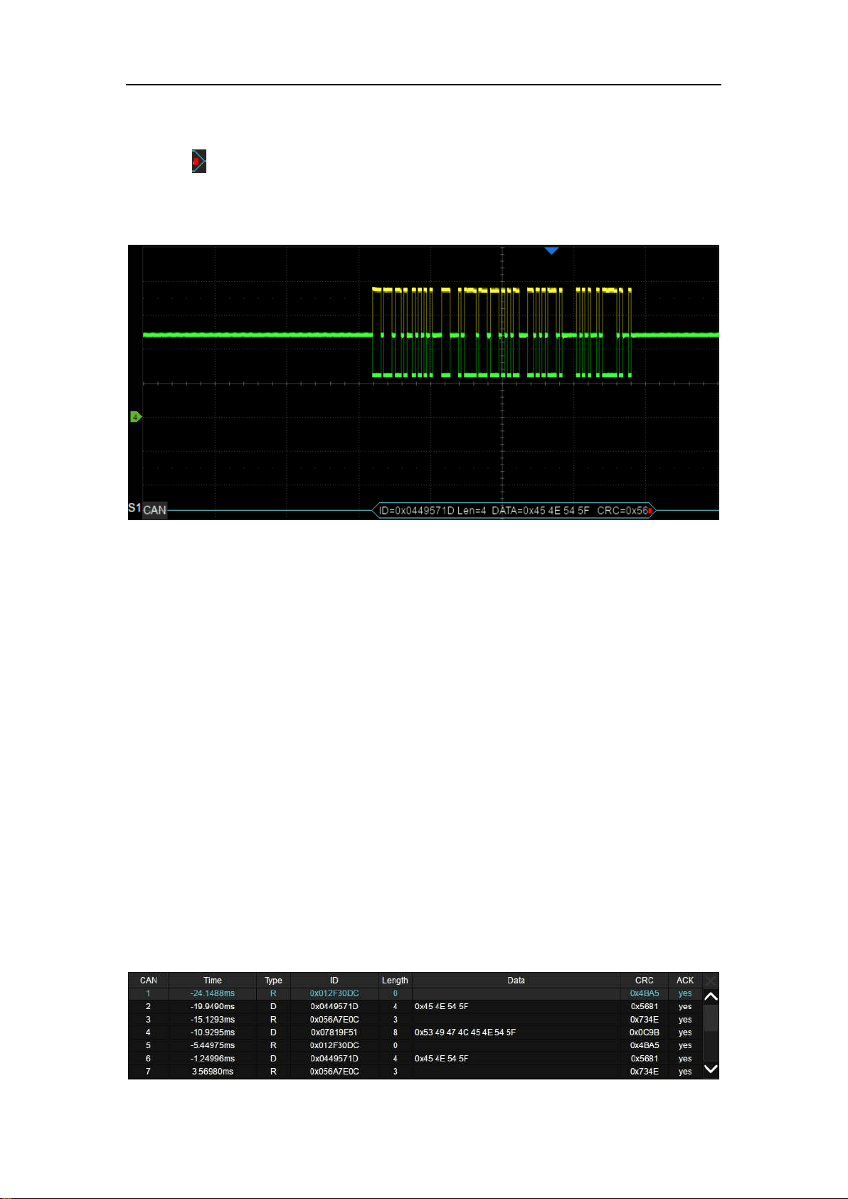
SDS5000X Series Digital Oscilloscope User Manual
128 / 236 W W W. S I G L E N T. C O M
ID, LEN (data length), DATA and CRC are all displayed in white.
indicates there is not enough space on the display to show complete
content of a frame and some content is hidden.
In the list:
Time — The horizontal offset of the current data frame head relative
to the trigger position.
Type — Type of the frame. Data frame is represented by "D" and
remote frame is represented by "R".
ID — ID of the frame, 11-bits or 29-bits ID are automatically detected.
Length — Data length.
Data — Data values.
CRC — Cycle redundancy check.
Ack — Acknowledge bit.

SDS5000X Series Digital Oscilloscope User Manual
129 / 236 W W W. S I G L E N T. C O M
16.6 LIN Trigger and Serial Decode
Please trigger and decode the LIN signals in the order of "LIN Signal Settings",
"LIN Trigger" and "LIN Serial Decode".
16.6.1 LIN Signal Settings
Connect the LIN signals to the oscilloscope, set correctly the mapping relation
between channels and signals, and then set the threshold level of each signal.
The process of specifying the source and threshold is similar to "I2C Signal
Settings".
In BusConfig menu of trigger and decode, baud rate can be set to:
600,1200,2400,4800,9600,19200 or Custom.
The method of copying settings is the same as I2C signal settings. See "I2C
Signal Settings" for details.
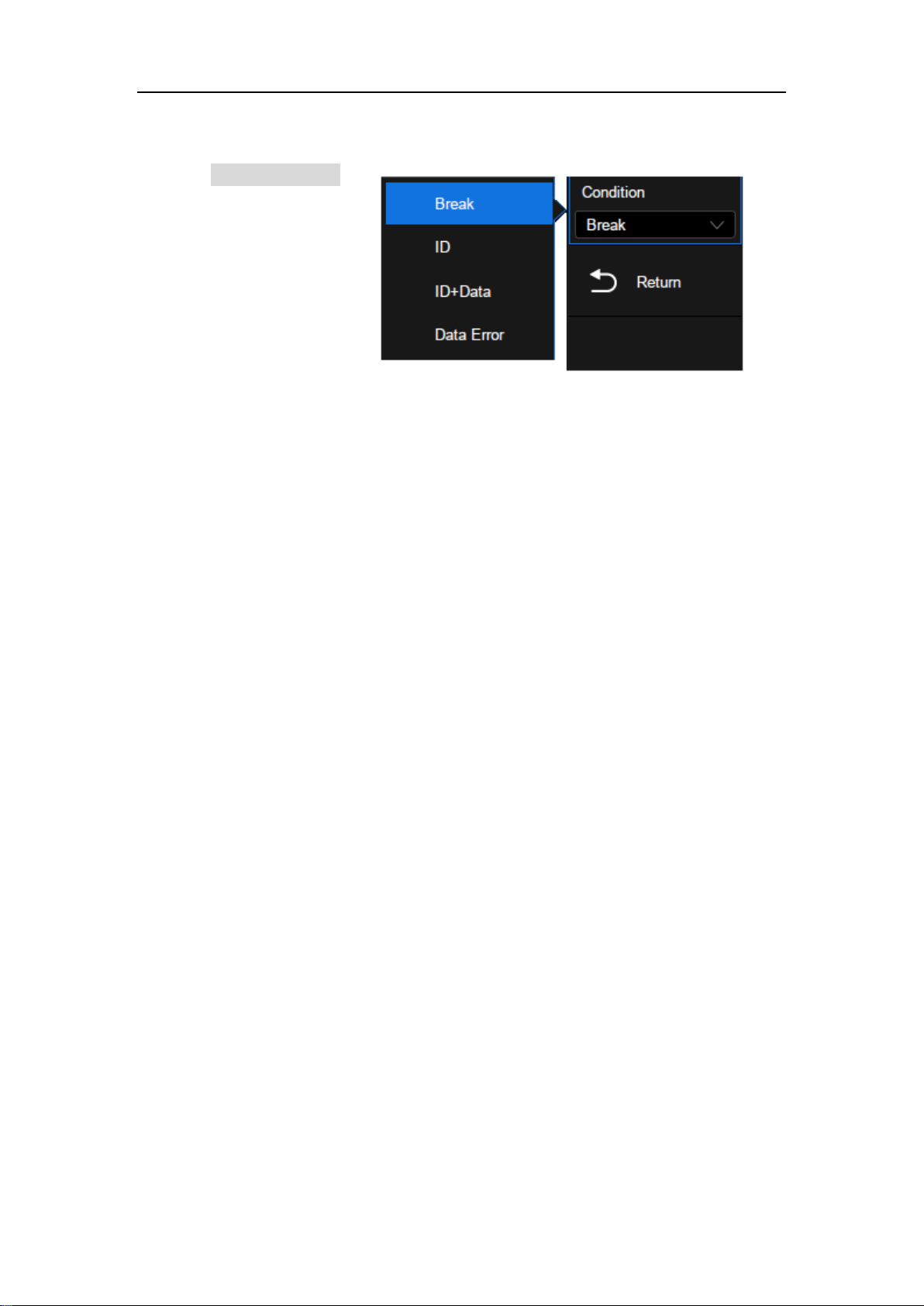
SDS5000X Series Digital Oscilloscope User Manual
130 / 236 W W W. S I G L E N T. C O M
16.6.2 LIN Trigger
Touch Trigger Setting
in the LIN trigger dialog
box to set the trigger
conditions:
Break — The oscilloscope triggers at the beginning of the frame.
ID — The oscilloscope triggers on the frame that matches the specified ID,
which ranges from 0x00 to 0x3f.
ID&Data
— The oscilloscope triggers on the frame that matches the
specified ID and data. ID, Data1 and Data2 can be set.
Data Error — The oscilloscope will trigger when data error happens.
16.6.3 LIN Serial Decode
The set of SPI decode is similar to that of I2C decode.
In the bus:
ID, LEN (data length), DATA and Chk are all displayed in white.
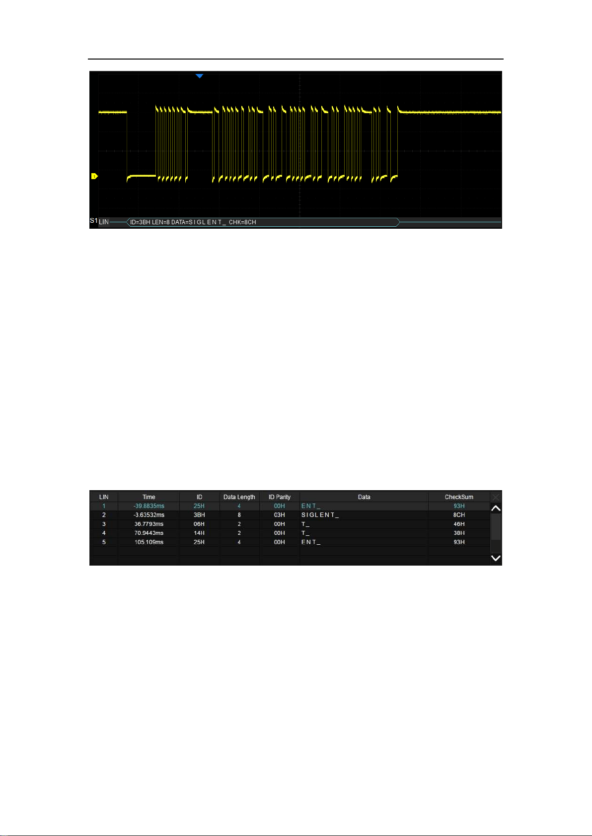
SDS5000X Series Digital Oscilloscope User Manual
131 / 236 W W W. S I G L E N T. C O M
In the list:
Time — The horizontal offset of the current data frame head relative
to the trigger position.
ID — ID of the frame.
Data length — Data length.
ID Parity — ID parity check.
Data — Data values.
Checksum — Data checksum.

SDS5000X Series Digital Oscilloscope User Manual
132 / 236 W W W. S I G L E N T. C O M
17 Cursors
17.1 Overview
Cursors are important tools when measuring signals. Rapid measurements can
be performed using cursors in both horizontal and vertical directions. The cursor
types includes X1, X2, X1-X2, Y1, Y2 and Y1-Y2, used to indicate X-axis values
(time or frequency) and Y-axis values (amplitude) on a selected waveform
(CH1/CH2/CH3/CH4/MATH/REFA/REFB/REFC/REFD).
Press the Cursors button on the front panel or touch the menu Cursors>Menu
to open cursors dialog box:
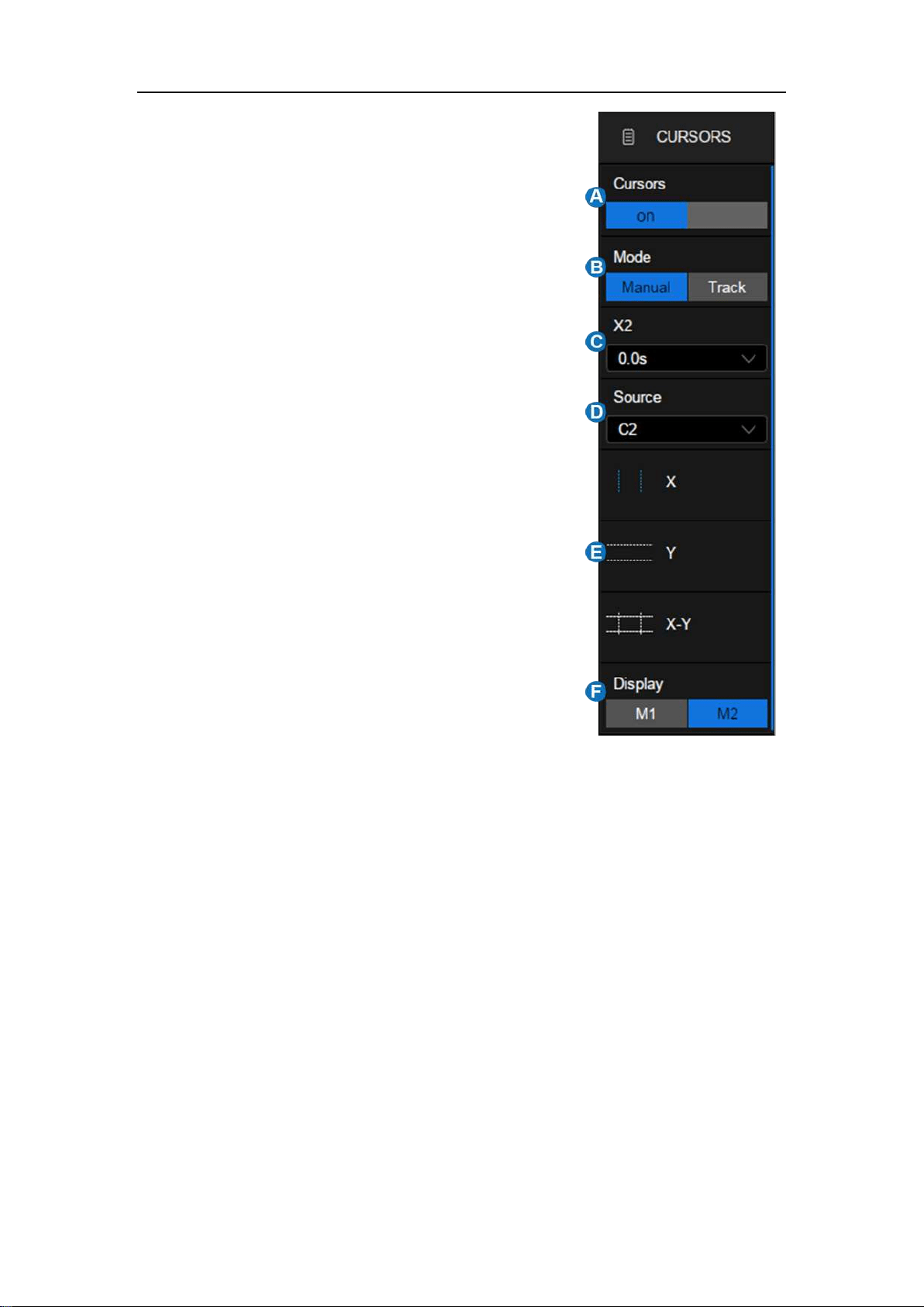
SDS5000X Series Digital Oscilloscope User Manual
133 / 236 W W W. S I G L E N T. C O M
A. Turn on or off cursors function
B. Cursors Mode. The vertical cursors
will automatically track the
waveform in Trace mode.
C. Specify the cursor and set the
position (by gestures, universal
knob, or virtual keypad)
D. Select the source
E. Cursors type (horizontal, vertical,
horizontal+vertical), this option is
supported only in "Manual" mode.
F. Display mode of cursors
Cursors Mode
Manual -- Manually set the cursors’ position. Cursors type (horizontal,
vertical, horizontal+vertical) is available in this mode.
Track -- The cursor type is automatically set to "horizontal+vertical". In this
mode, only horizontal cursors are adjustable, while the vertical cursors
automatically attach to the cross-point of the cursor and the source
waveform.
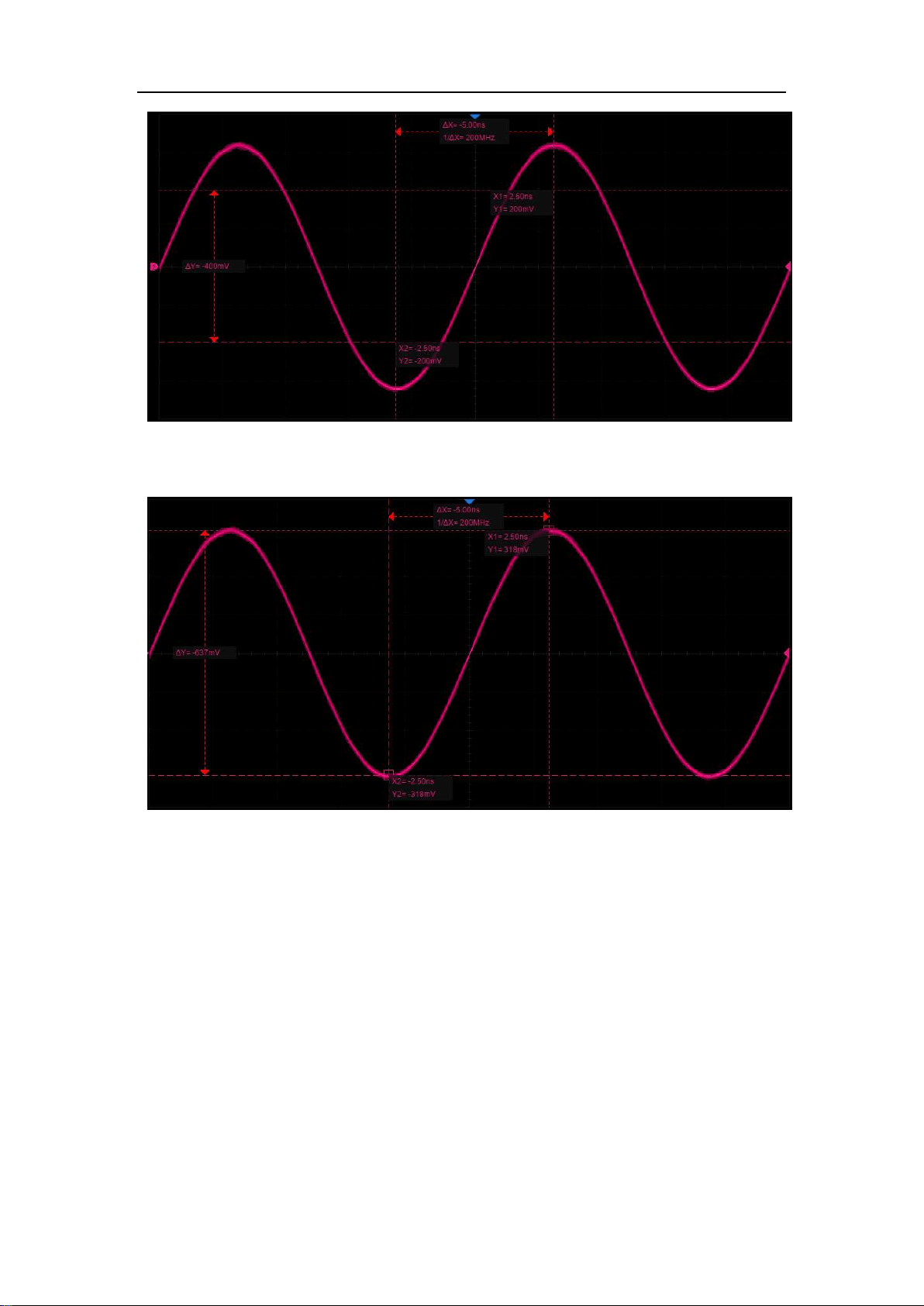
SDS5000X Series Digital Oscilloscope User Manual
134 / 236 W W W. S I G L E N T. C O M
Manual Mode
Track Mode
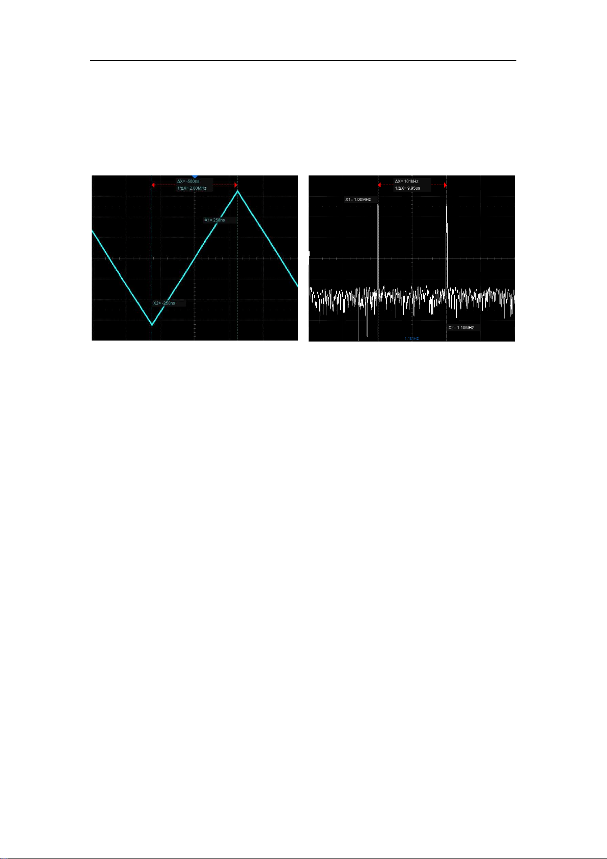
SDS5000X Series Digital Oscilloscope User Manual
135 / 236 W W W. S I G L E N T. C O M
Cursors Type
X (horizontal) -- Vertical dotted lines that measure horizontal time (when the
source is an FFT waveform, X cursors measure frequency).
X cursors (time)
X cursors (frequency)
X1 — The left (default) vertical dotted line. It can be manually moved
to any horizontal position on the screen.
X2 — The right (default) vertical dotted line. It can be manually
moved to any horizontal position on the screen.
X1- X2 — The difference between X1 and X2. After this option is
selected, turning the universal knob will move both X1 and X2
simultaneously.
Y(vertical)– Horizontal dotted lines that measure vertical voltage or current
(depending on the unit of the selected channel). When the cursors source is the
math function, the units will match the math function.

SDS5000X Series Digital Oscilloscope User Manual
136 / 236 W W W. S I G L E N T. C O M
Y1 — The upper (default) horizontal dotted line. It can be manually
moved to any vertical position on the screen.
Y2 — The lower (default) horizontal dotted line. It can be manually
moved to any vertical position on the screen.
Y1- Y2 — The difference between Y1 and Y2. After this option is
selected, turn the universal knob to move both Y1 and Y2
simultaneously.
X+Y (horizontal+vertical) -- Both the X cursors and Y cursors are enabled.

SDS5000X Series Digital Oscilloscope User Manual
137 / 236 W W W. S I G L E N T. C O M
Display Mode
Display Mode M1
Display Mode M2
M1 – The position information of each cursor is attached to the cursor, and
the difference information is between the two cursors with arrows
connected to the cursors. This mode is more intuitive.
M2 -- The position information of each cursor and the difference between
the cursors are displayed in a region on the screen. The region can be
moved by gestures to avoid covering the waveform. This mode is relatively
concise.
17.2 Select and Move Cursors
The cursors can be selected and moved directly by gestures and the universal
knob on the front panel, in addition they can be selected in the cursors dialog
box.
Gestures
Directly touch the cursor and drag it, as shown below:
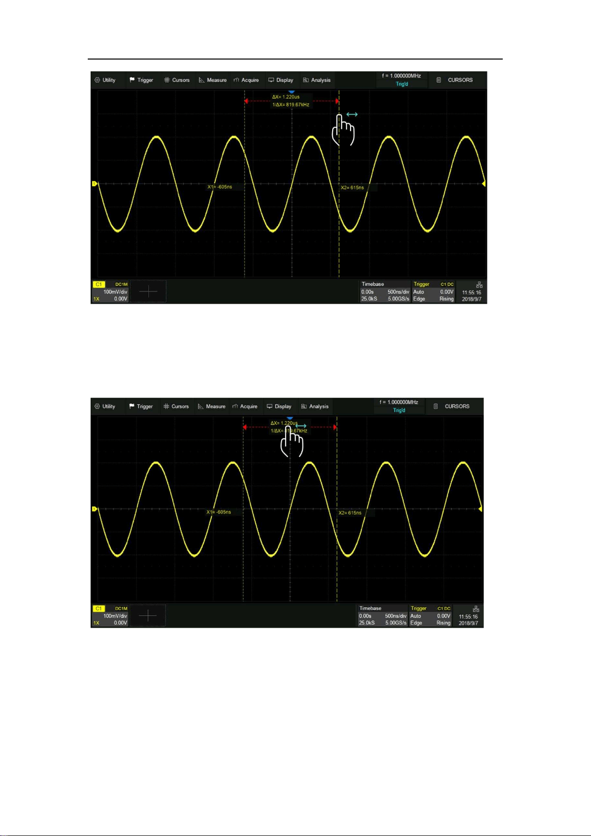
SDS5000X Series Digital Oscilloscope User Manual
138 / 236 W W W. S I G L E N T. C O M
Touch the display area of △X (or△Y) in M1 mode and drag it to move the two
cursors simultaneously, as shown in the figure below. This is equivalent to the
operation on the cursor type X1-X2 or Y1-Y2.
Universal Knob
Move the cursor position by turning the universal knob on the front panel. Press
the knob to select different cursor lines. For example, if the current cursor is X1,
press to select X2, and press again to select X1-X2.
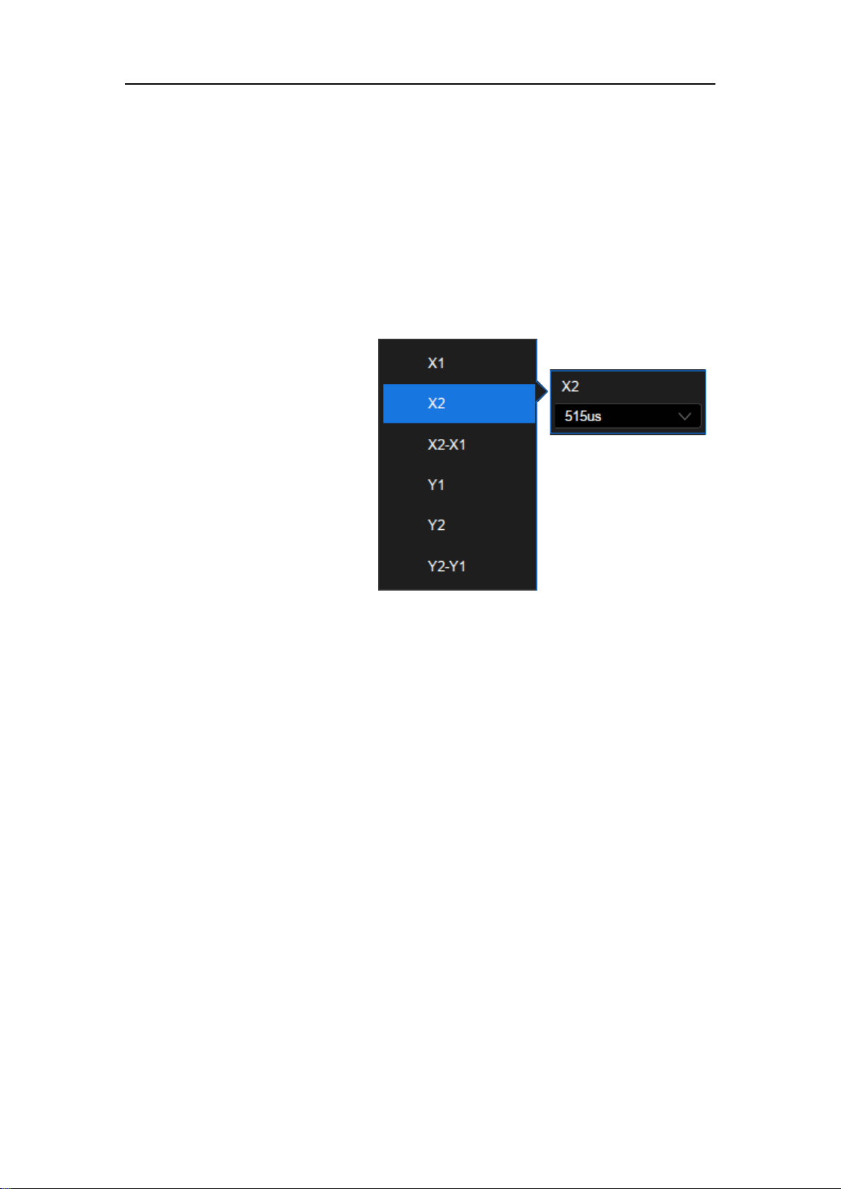
SDS5000X Series Digital Oscilloscope User Manual
139 / 236 W W W. S I G L E N T. C O M
Gestures move the cursor quickly but not precisely, while the knob moves the
cursor precisely but not as quickly. You can use both in combination to suit your
needs: First, a rough adjustment is achieved by using gestures and then fine
adjustment is achieved by using the universal knob.
Dialog Box
Touch the cursor name area
of the dialog box, select the
cursor(s) in the pop-up list,
and then rotate the
universal knob to adjust the
position.

SDS5000X Series Digital Oscilloscope User Manual
140 / 236 W W W. S I G L E N T. C O M
18 Measurement
18.1 Overview
The SDS5000X features a strong automatic measurement list. These
parameters can be automatically measured without cursors. Included are
common measurements such as rise time, fall time, peak-peak, and period. The
SDS5000X can also measure multiple channels at the same time, showing up
to 5 parameter measurements with and statistics at one time. If you wish to view
more than 5 parameters on a specified channel, then the "All Meas" function
can be employed. For measuring waveform of interest in a time gate, the "Gate"
function is suggested.
Some parameter measurements (such as mean) may be a value generated by
all the data in a frame. Some parameter measurements (such as period)
accumulate all measurements in a frame, but the displayed value is always the
first value. If you want to know the distribution of multiple parameters in one
frame, you should use the statistics function.
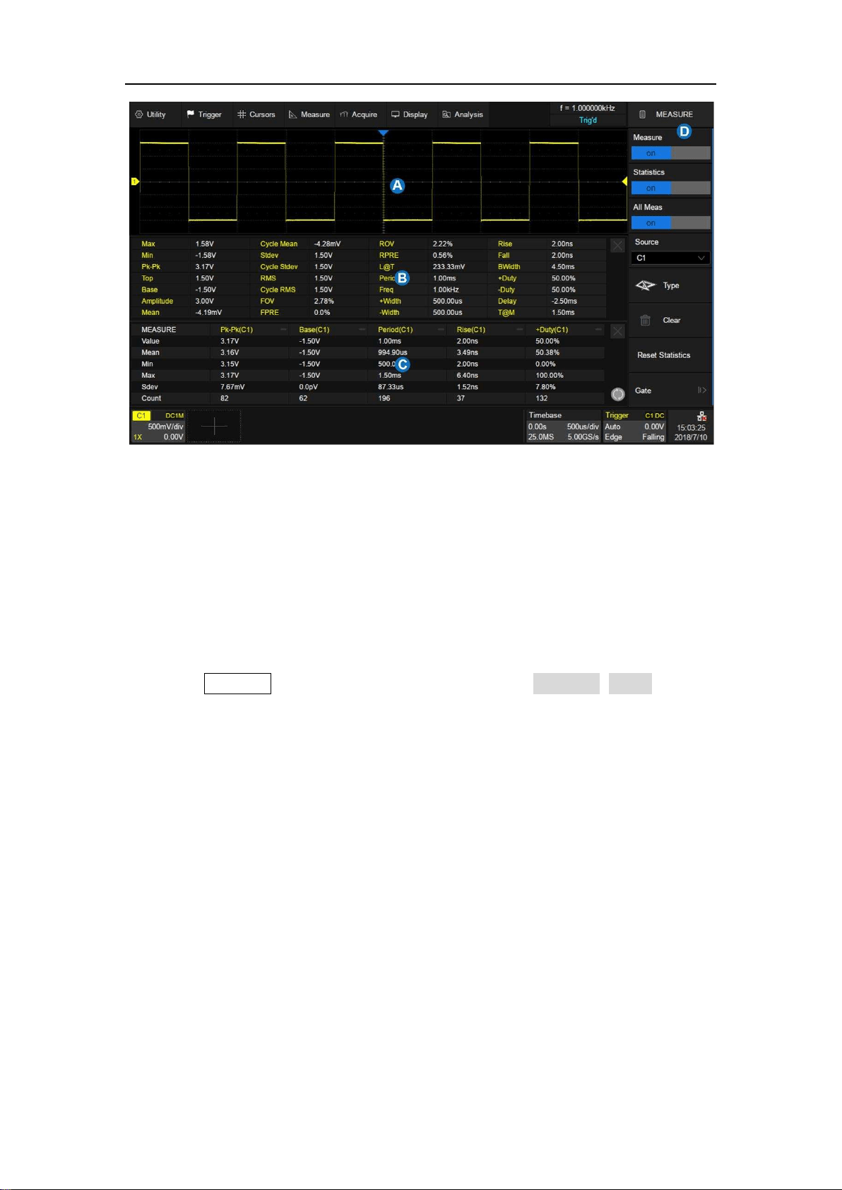
SDS5000X Series Digital Oscilloscope User Manual
141 / 236 W W W. S I G L E N T. C O M
A. Waveform display area, automatically compresses when the other
windows are displayed
B. “All Meas” parameter display area
C. Measurement parameters and statistics display area
D. Measure dialog box
Press the Measure button on the front panel or touch Measure>Menu to open
the dialog box.
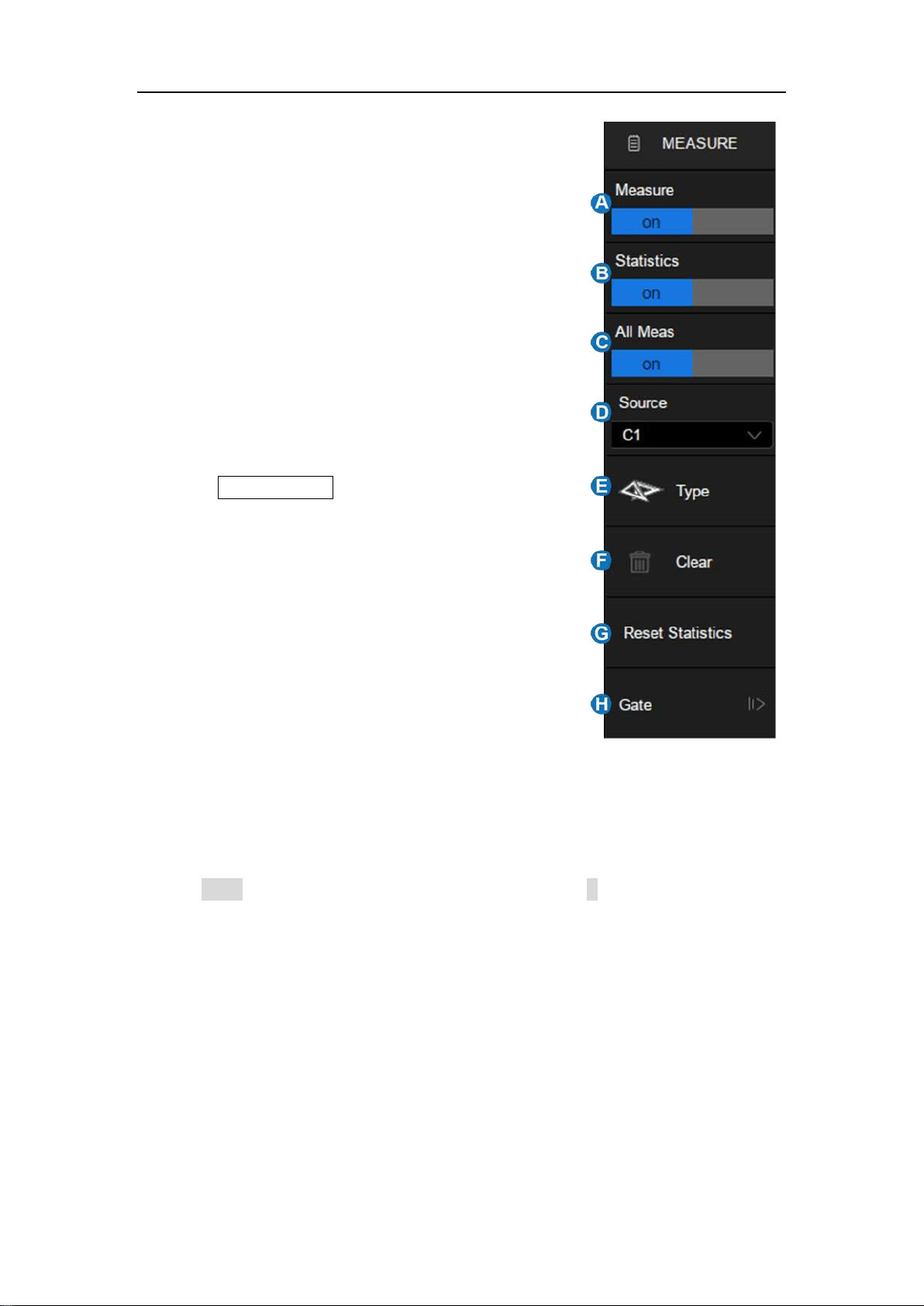
SDS5000X Series Digital Oscilloscope User Manual
142 / 236 W W W. S I G L E N T. C O M
A. Turn on or off measure
B. Turn on or off the statistics
C. Turn on or off all measure. It will show all
measurements of the specified channel.
D. Select the source of the measurement
E. Select measurement parameters
F. Clear all the selected measurements
G. Clear and restart the statistics Pressing the
Clear Sweeps button on the front panel has
an equivalent effect.
H. Set the time gate for measurement.
18.2 Set Parameters
Touch Type in the measure dialog box, or touch + in the measurement
parameters and statistics display area to open the parameter selection window:
SDS5000X Series Digital Oscilloscope User Manual
143 / 236 W W W. S I G L E N T. C O M
A. Indicates the source of the current setting.
B. Measurement parameter classification tabs, including vertical
measurement, horizontal measurement and channel delay (CH Delay)
measurement. Touch a tab and in the area will display the
corresponding parameters
C. Parameters. Touch the parameter to be measured to activate it, and
touch it again to close the parameter.
D. Background highlighted parameters represent it is activated. In the
figure above, "Pk-Pk" and "ROV" are activated.
E. Description of the last selected parameter.
The correct steps to add a measurement parameter are to select the source in
the Source area of the dialog box and then select the parameter in the
parameter window. For example, to add Pk-Pk measurements for C1 and
Period measurements for C2, follow the steps below:
Source>C1>Vertical>Pk-Pk
Source>C2>Horizontal>Period
SDS5000X Series Digital Oscilloscope User Manual
144 / 236 W W W. S I G L E N T. C O M
For the channel delay (CH Delay) measurement, because the number of
sources involved is greater than 1,
the steps to specify the source is different:
In the parameter selection area, the channel corresponding to Source A is
specified first, and then the channel corresponding to Source B. Finally, the
measurement parameter is selected. For example, to activate the skew
between C1 and C2, you can follow the following steps:
Source A>C1>Source B>C2>Skew
Once a parameter is selected, it will appear in the parameter and statistical
display area below the grid:
Touch + in the blank area to add a parameter.
Touch – in the upper right corner of each parameter to close the parameter.
Touch × in the upper right corner of the area to close measurement.
Touch Clear in the dialog box to close all parameters.
SDS5000X Series Digital Oscilloscope User Manual
145 / 236 W W W. S I G L E N T. C O M
18.3 Type of Measurement
18.3.1 Vertical Measurement
Vertical measurement includes 17 parameters:
Max: Highest value in the input waveform
Min: Lowest value in the input waveform
Pk-Pk: Difference between maximum and minimum data values
Top: Value of most probable higher state in a bimodal waveform
Base: Value of most probable lower state in a bimodal waveform
Amplitude: Difference between top and base in a bimodal
waveform. If not bimodal, the difference between max and min
Mean: Average of data values
Cycle Mean: Average of data values in the first cycle
SDS5000X Series Digital Oscilloscope User Manual
146 / 236 W W W. S I G L E N T. C O M
Stdev: Standard deviation of the data
Cycle Stdev: Standard deviation of the data in the first cycle
RMS: Root mean square of the data
Cycle RMS: Root mean square of the data in the first cycle
Overshoot (FOV): Overshoot following a falling edge; 100%*
(base-min)/amplitude
Overshoot (ROV): Overshoot following a rising edge; 100%*(max-
top)/amplitude
Preshoot (FPRE): Overshoot before a falling edge.
Equal to 100%*(max-top)/amplitude.
Preshoot (RPRE): Overshoot before a rising edge.
Equal to 100%*(base-min)/amplitude.
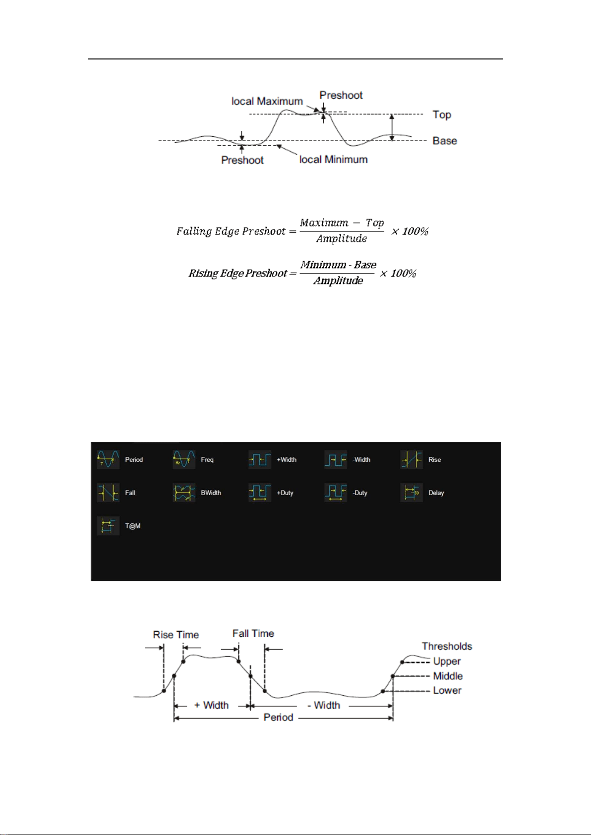
SDS5000X Series Digital Oscilloscope User Manual
147 / 236 W W W. S I G L E N T. C O M
L@T: Level measured at trigger position
18.3.2 Horizontal Measurement
Horizontal measurement includes 11 parameters:

SDS5000X Series Digital Oscilloscope User Manual
148 / 236 W W W. S I G L E N T. C O M
Period: Time between the middle threshold points of two
consecutive like-polarity edges.
Freq: Reciprocal of period
+Width: Time difference between the 50% threshold of a rising
edge to the 50% threshold of the next falling edge of the pulse
-Width: Time difference between the 50% threshold of a falling
edge to the 50% threshold of the next rising edge of the pulse
Rise: Duration of rising edge from 10-90%
Fall: Duration of falling edge from 90-10%
BWidth: Time from the first rising edge to the last falling edge or
the first falling edge to the last rising edge at the 50% crossing
+Duty: Positive Duty Cycle. Ratio of positive width to period
-Duty: Negative Duty Cycle. Ratio of negative width to period
Delay: Time from the trigger to the first transition at the 50%
crossing
T@M: Time from the trigger to each rising edge at the 50%
crossing
18.3.3 Delay Measurement
Delay measurement measures the time difference between two channels. It
includes 10 delay parameters:

SDS5000X Series Digital Oscilloscope User Manual
149 / 236 W W W. S I G L E N T. C O M
Phase: Phase difference between two edges
FRFR:The time between the first rising edge of source A and
the following first rising edge of source B at the 50% crossing
FRFF:The time between the first rising edge of source A and
the following first falling edge of source B at the 50% crossing
FFFR
:The time between the first falling edge of source A and
the following first rising edge of source B at the 50% crossing
FFFF:The time between the first falling edge of source A and
the following first falling edge of source B at the 50% crossing
FRLR:The time between the first rising edge of source A and
the last rising edge of source B at the 50% crossing
FRLF: The time between the first rising edge of source A and
the last falling edge of source B at the 50% crossing
FFLR: The time between the first falling edge of source A and
the last rising edge of source B at the 50% crossing
FFLF
:The time between the first falling edge of source A and
the last falling edge of source B at the 50% crossing
Skew: Time of source A edge minus time of nearest source B
edge
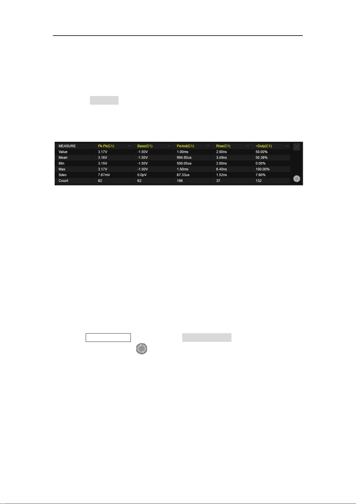
SDS5000X Series Digital Oscilloscope User Manual
150 / 236 W W W. S I G L E N T. C O M
18.4 Measurement Statistics
Enable the Statistics function to observe distribution of the measured values of
every selected parameter.
Value – The current measurement
Mean – Average of all historical measurements
Min – The minimum of all historical measurements
Max – The maximum of all historical measurements
Stdev – Standard deviation of all historical measurements
Count – The number of historical measurements
Press the Clear Sweeps button or touch Reset Statistics in the measure dialog
box, or touch the symbol in the statistics display area to clear and restart
statistics.
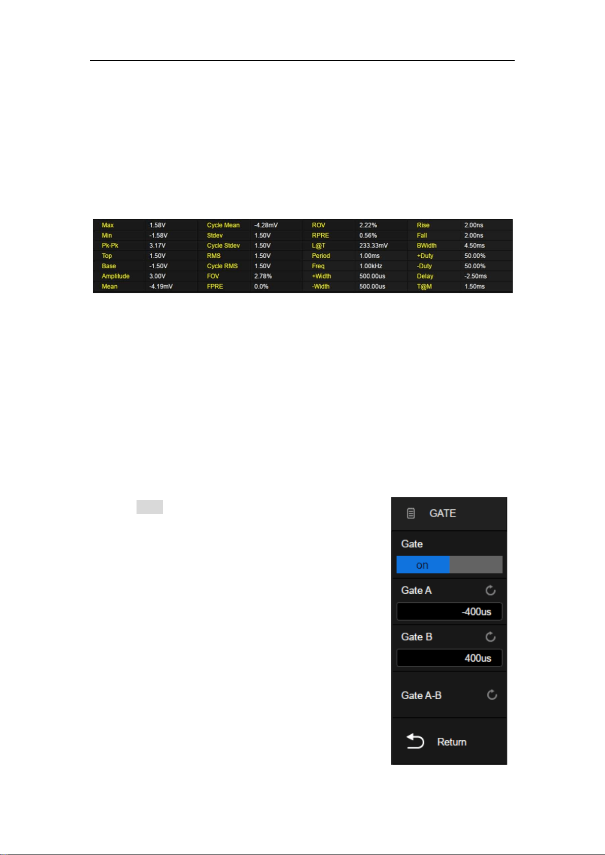
SDS5000X Series Digital Oscilloscope User Manual
151 / 236 W W W. S I G L E N T. C O M
18.5 All Measurement
Enabling All Measurement displays all vertical and horizontal measurement
parameters of the specified channel at the same. The font color of the
measurement parameters is consistent with the color of the specified source.
18.6 Gate
Sometimes the user may want to measure parameters for a certain specified
time range of the signal and ignore signal parts that lie outside of that range. In
this case, the Gate function can be helpful.
Touch Gate in the measure dialog box, then two
horizontal cursors A and B will appear in the grid
area. The gate setting dialog box will be displayed
on the right.
Gate cursors A and B are used to define the range of
time for parameter measurements. The oscilloscope
only measures the parameters of the data between A
and B, ignoring the data outside the range.
The setting of gate cursors is similar to that of
ordinary cursors. See "Select and Move Cursors" for
details.
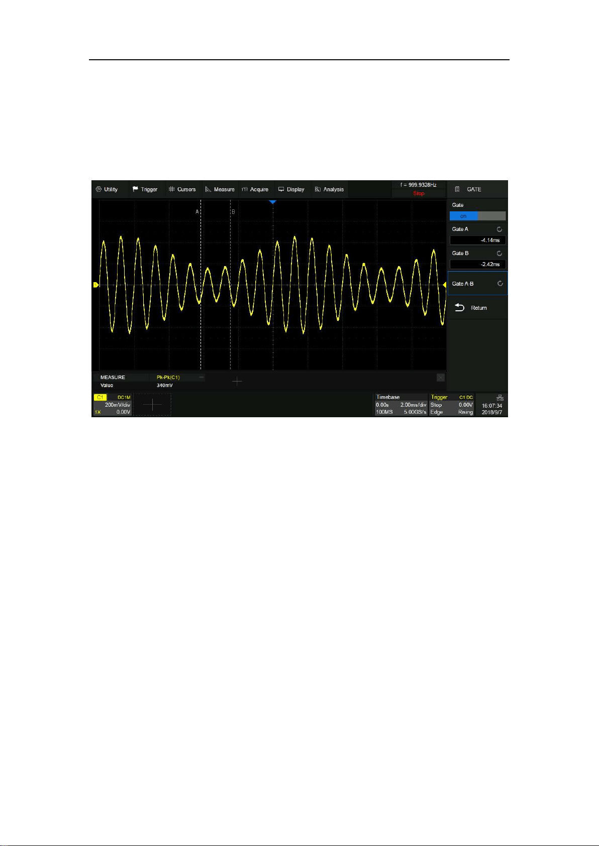
SDS5000X Series Digital Oscilloscope User Manual
152 / 236 W W W. S I G L E N T. C O M
The figure below shows a scenario in which the gate function is used to
measure the peak-peak parameter of the trough of an amplitude modulated
waveform:

SDS5000X Series Digital Oscilloscope User Manual
153 / 236 W W W. S I G L E N T. C O M
19 Math
19.1 Overview
The SDS5000X supports multiple math operations on the analog channels,
including addition (+), subtraction (-), multiplication (x), division (/), FFT,
differential (d/dt), integral (∫dt), square root (√) and FFT. The math trace is
displayed in white and labeled with an “M” icon. It can be measured by the
cursors or as the source of auto measurement.
Press the MATH button on the front panel, or touch + in the channel descriptor
box region and select Math, and then math dialog box pops up:
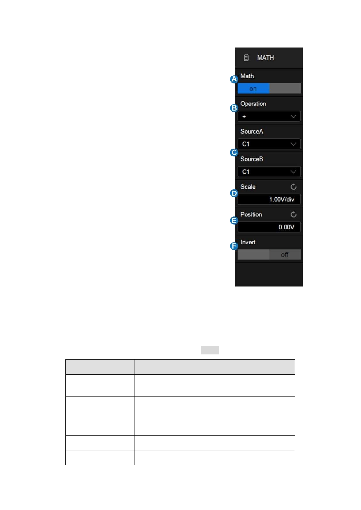
SDS5000X Series Digital Oscilloscope User Manual
154 / 236 W W W. S I G L E N T. C O M
A. Turn on or off math operation
B. Select the operation
C. Select the source. The number of sources
corresponding to different operators is
different. Addition, subtraction,
multiplication and division have two
sources, while others have only one.
D. Set the vertical scale of the math operation
E. Set the vertical position of the math
operation. The vertical scale and position
of the math can also be set by knob,
referring to "Decode/Digital/Math/Ref ".
F. Turn on or off invert, that is similar to the
process used in "Vertical Setup".
Units for Math Waveform
Different operations corresponding to the operation results have different
dimensions. Therefore, the units displayed in Scale are different:
Math Operation
Unit
Addition (+) or
Subtraction (-)
V, A, or U (used when the units of two sources are not
consistent)
Multiplication (x)
V
∧
2, A
∧
2, or W
Division (/)
None, Ω (Resistance unit Ohm), S (conductance unit
Siemens)
FFT
dBVrms, Vrms, dBArms, Arms, dBm
d/dt
V/S (Volt/Second) or A/S (A/Second)
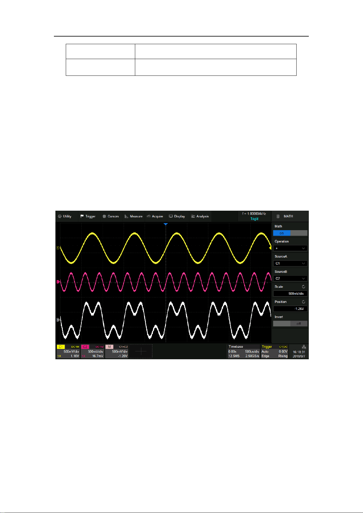
SDS5000X Series Digital Oscilloscope User Manual
155 / 236 W W W. S I G L E N T. C O M
∫dt
VS (Volt*Second)0 or AS (A*Second)
√
V
∧
0.5 or A
∧
0.5
19.2 Addition/Subtraction/Multiplication/Division
The SDS5000X can perform arithmetic operations including addition,
subtraction, multiplication or division on any two analog input channels. The
values of Source A and Source B are computed point-by-point.
The following figure shows an example of MATH = C1 + C2:
19.3 Differential
The differential (d/dt) operator is used to calculate the derivative of the selected
source. It is always used to measure the instantaneous slope of the waveform,
such as the slew rate of an operational amplifier. The differential equation is:
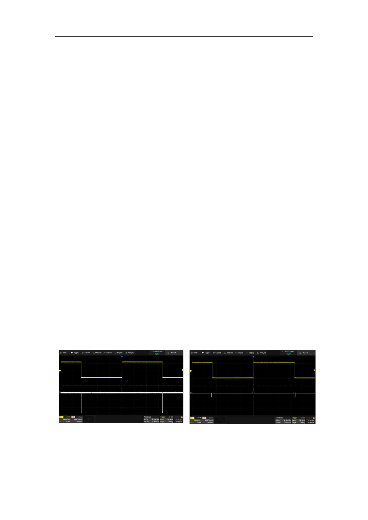
SDS5000X Series Digital Oscilloscope User Manual
156 / 236 W W W. S I G L E N T. C O M
dx
y(i) - dx)+(iy
di
Where:
d = Differential result
y = Values of source data
i = Data point index
dx = Differential interval
The range of “dx” in the d/dt menu is1~20. The measurement units are point
and the corresponding time difference range is 0.01~0.20 div. “div” indicates
the number of the pixel points that each division has and is 100 for the
SDS5000X.
If dx = 10 points, the time difference is:
0.01*10 = 0.1 div
Then the differential operator calculates the "average slope in 10 points" of the
selected source and dx represents the time difference between the 10 sampled
points.
dx = 1
dx = 5
Note: Differentiation is sensitive to noise. It is helpful to set the acquisition mode
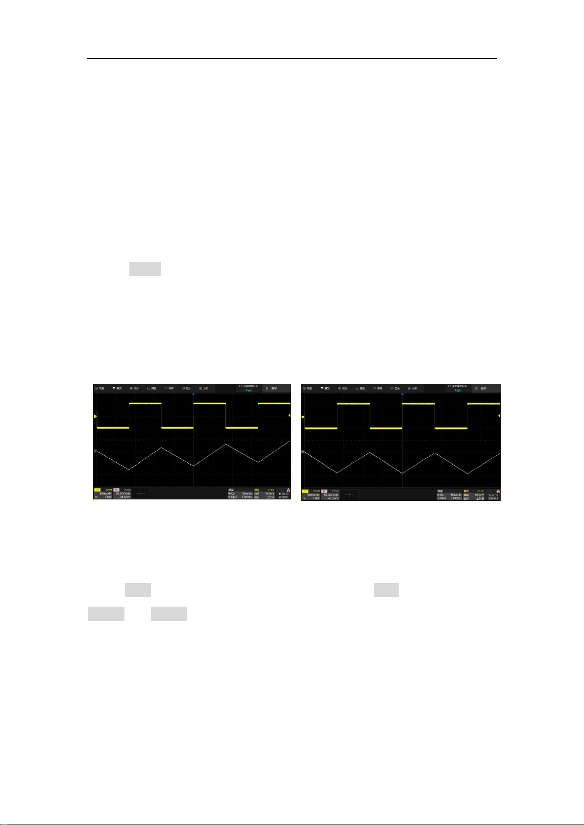
SDS5000X Series Digital Oscilloscope User Manual
157 / 236 W W W. S I G L E N T. C O M
to “Average” or “Eres” to help minimize the visible effects of additional noise.
19.4 Integral
Integral operation integrates the waveforms on the screen or within the
specified gate.
Setting Offset in the integral menu provides an approach to correct the DC
offset of the source. Small DC offsets in the input signal (or even small offset
errors of the oscilloscope itself) may cause the integral output to "ramp" up or
down.
Integral without Offset
Integral with Offset
In addition, the integral operation can be performed within a specified gate.
Touch Gate area in the math dialog box, and enable Gate function, then set
Gate A and Gate B to define the gate. The setting of the gate cursors is similar
to that of normal cursors. See "Select and Move Cursors" for details.
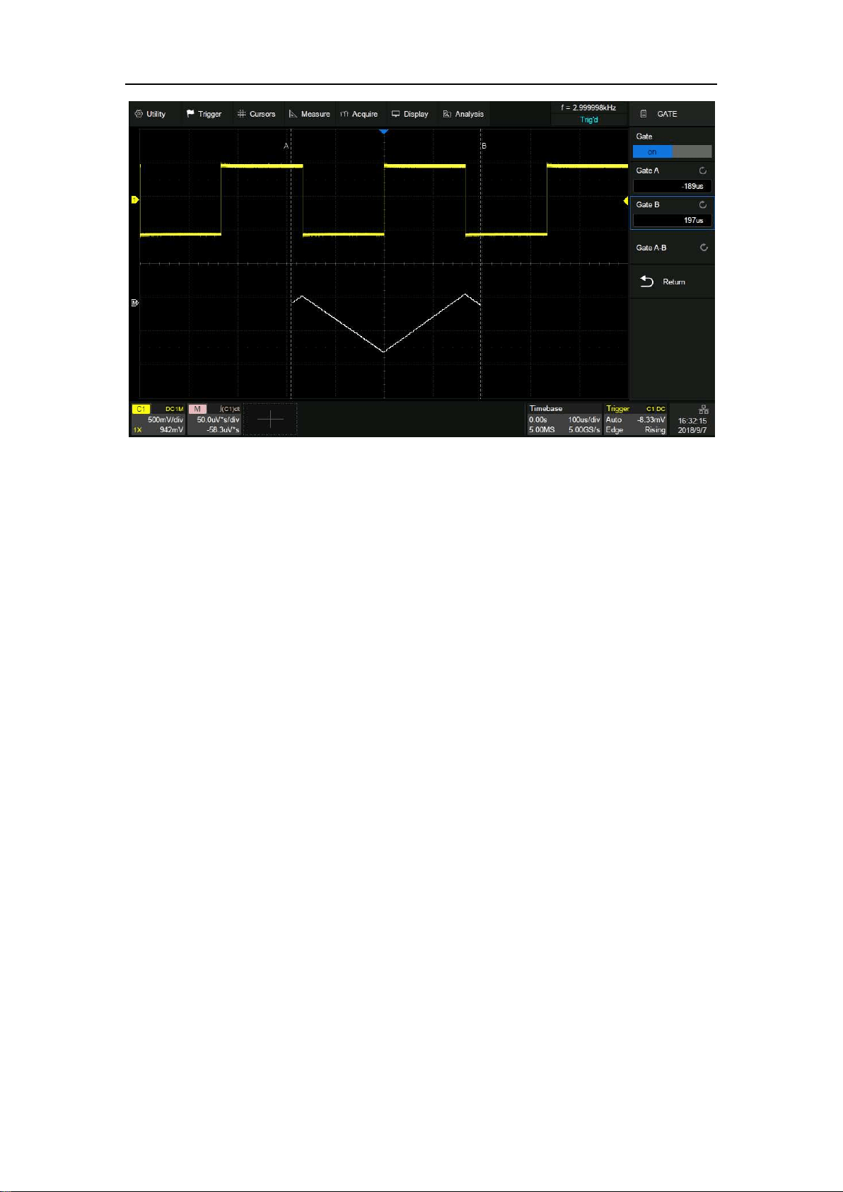
SDS5000X Series Digital Oscilloscope User Manual
158 / 236 W W W. S I G L E N T. C O M

SDS5000X Series Digital Oscilloscope User Manual
159 / 236 W W W. S I G L E N T. C O M
19.5 Square Root
Square root (√) calculates the square root of selected source. If the waveform
value is negative (the waveform is below the ground level), the result is
displayed as zero.
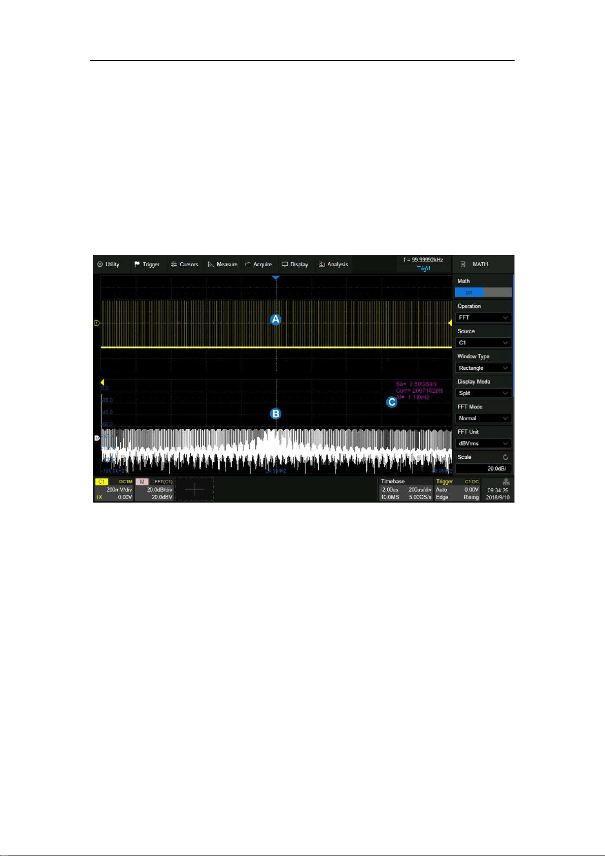
SDS5000X Series Digital Oscilloscope User Manual
160 / 236 W W W. S I G L E N T. C O M
19.6 FFT
The result of FFT (Fast Fourier Transform) calculations is the frequency
spectrum of the source signal. The horizontal axis of the FFT display is labeled
using frequency (Hz) units instead of time (second). In addition, the vertical axis
provides the option of logarithmic scaling (dBVrms/dBArms or dBm).
A. Time-domain waveform display area
B. Spectrum (FFT) waveform display area
C. FFT parameter display area
Parameter Display Area
The FFT parameters are displayed in upper right of the spectrum waveform
display area:

SDS5000X Series Digital Oscilloscope User Manual
161 / 236 W W W. S I G L E N T. C O M
FFT sample rate (Sa): FFT operation results present the first Nyquist zone
(DC ~ Sa/2) of the frequency spectrum. Be aware that the FFT sample rate
may be inconsistent with the sample rate in the time domain.
When the number of points in time domain, N, is less than 2 Mpts, the
FFT takes the number which is an integer power of 2 closest to N. In
this case, FFT sample rate = sample rate in time domain.
When N is greater than 2 Mpts, FFT first decimates N by D, and then
takes the first 2 Mpts for the calculation. In this case, FFT sample rate
= sample rate in time domain/D.
For example, in the case of sample rate in time domain is 5 GSa/s and
number of samples is 5 Mpts, FFT first decimates the samples by 2, to
2.5 Mpts, and then take the first 2 Mpts to calculate the spectrum. In
this example, FFT sample rate = 5 GSa/s ÷ 2 = 2.5 GSa/s.
FFT points (Curr): The current FFT points, which is an integer power of 2.
The SDS5000X supports up to 2M (2097152) points.
Frequency interval (△f): The frequency interval between two adjacent
points in the FFT sequence, which is proportional to the frequency
resolution.
Average count of FFT (Avg): Displayed only when the FFT mode is set to
"Average", indicating the completed average count.
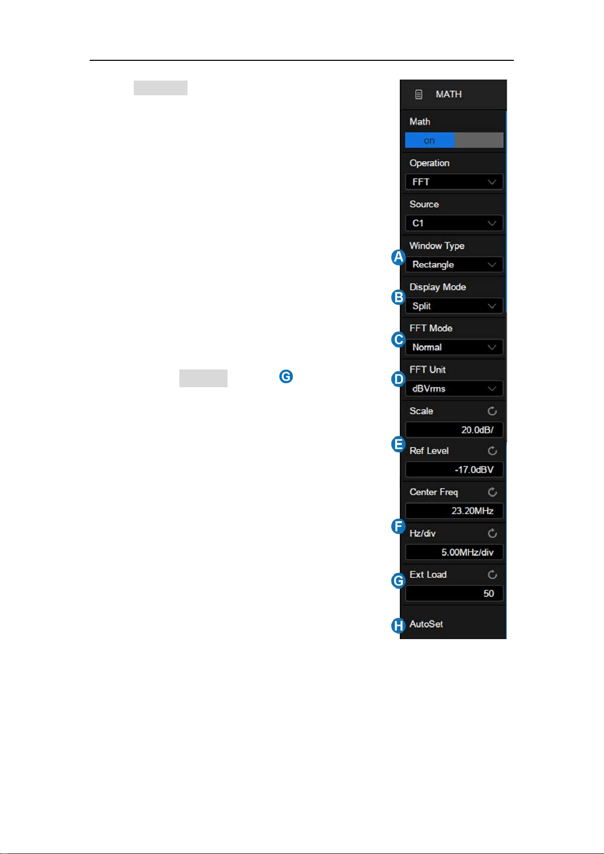
SDS5000X Series Digital Oscilloscope User Manual
162 / 236 W W W. S I G L E N T. C O M
Select Operation as FFT in the math dialog box and
set the parameters of FFT:
A. Set the window type (Rectangle, Blackman,
Hanning, Hamming and Flattop)
B. Select the display mode (Split, Full Screen
and Exclusive)
C. Select the FFT mode (Normal, Average and
Max-Hold)
D. Set the unit (dBVrms, Vrms and dBm). When
the unit is dBm, the oscilloscope will
automatically calculate the dBm value based
on the Ext Load value in area
E. Set the vertical scale and reference level
F. Set the center frequency and horizontal
scale
G. Set the external load, which is used to
calculate the correct dBm result
H. Automatically set vertical scale, reference
level, center frequency and horizontal scale
according to the maximum frequency
component in the previous frame
Note: The FFT dialog box is longer than the display. Slide the dialog box area
up and down by gestures, or scroll the mouse wheel to the undisplayed area.

SDS5000X Series Digital Oscilloscope User Manual
163 / 236 W W W. S I G L E N T. C O M
Windows
Spectral leakage in FFT can be considerably decreased when a window is used.
SDS5000X provides five windows which have different characteristics and are
applicable to different scenarios.
For example, for a two-tone signal with very close frequency interval, it is
suitable to use Rectangle window with the best frequency resolution. For the
case where the accuracy of amplitude measurement is critical, it is
recommended to select Flattop window with the best amplitude resolution.
Window
Characteristics
Main lobe
width
Side lobe
suppression
Maximum
amplitude
error
Rectangle
The best frequency
resolution
The worst
amplitude
resolution
It is equivalent to
the case of no
window
23 is
-13 dB
3.9 dB
Hanning
Better frequency
resolution
Poor amplitude
resolution
8oor
-32 dB
1.4 dB
Hamming
Better frequency
resolution
Poor amplitude
resolution
8oor
-43 dB
1.8 dB
Blackman
Poor frequency
resolution
Better amplitude
resolution
12π/N
-58 dB
1.1 dB
Flattop
Poor frequency
resolution
23mpl
-93 dB
< 0.1 dB
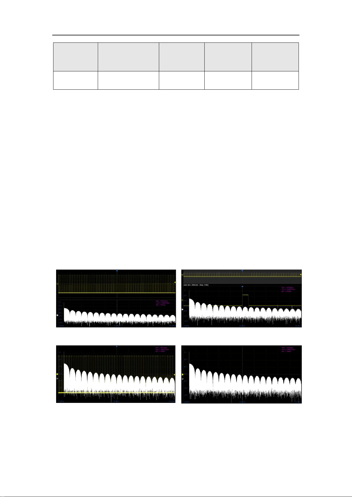
SDS5000X Series Digital Oscilloscope User Manual
164 / 236 W W W. S I G L E N T. C O M
Window
Characteristics
Main lobe
width
Side lobe
suppression
Maximum
amplitude
error
The best amplitude
resolution
Display Mode
Split: Time domain waveform and frequency domain waveform are
displayed separately. The time domain waveform is on the upper half
screen, while the frequency domain waveform is located within the lower
half of the display. In Split mode, if Zoom is enabled, the zoom waveform
and the frequency domain waveform are displayed on the lower half screen
together.
Full Screen: Time-domain waveform and frequency-domain waveform are
displayed together.
Exclusive: Only the frequency-domain waveform is displayed.
Split Mode, Zoom off
Split Mode, Zoom on
Full Screen Mode
Exclusive Mode
FFT Mode

SDS5000X Series Digital Oscilloscope User Manual
165 / 236 W W W. S I G L E N T. C O M
Normal: Displays the FFT result of each frame directly.
Max-Hold: Holds the maximum value in the historic frame on the display.
This mode is suitable for detecting discontinuous waves, such as sporadic
pulse signals, or frequency hopping signals. Press the Clear Sweeps button
on the front panel to clear the max-hold waveform.
Average: Reduces the effect of the superimposed random noise on the
signal. After the FFT mode is set as Average, Average will appear under
FFT Mode. The average count can be set here, ranging from 4 to 1024.
Press the Clear Sweeps on the front panel or touch Reset in the dialog box
to restart the average counter.
Unit
The unit of the vertical axis can be set to dBm, dBVrms or Vrms. dBVrms and
Vrms respectively use logarithmic scale and linear scale. dBVrms is
recommended to show larger dynamic range. dBm is a power unit, the correct
result can be obtained only if the value of Ext Load is set to be consistent with
the load impedance of the actual measured signal.
Vertical Control
Touch Ref Level to set the reference level of FFT waveform by the universal
knob or the virtual keypad. It can also be set by the offset knob shared by
Decode, Digital, Math and Ref on the front panel.
Touch Scale to set the vertical scale of FFT waveform by the universal knob or
the virtual keypad. It can also be set by the scale knob shared by Decode,
Digital, Math and Ref on the front panel. The reference point for vertical scale

SDS5000X Series Digital Oscilloscope User Manual
166 / 236 W W W. S I G L E N T. C O M
scaling is the reference level.
Horizontal Control
Touch Center Freq to set the center frequency of FFT waveform by the
universal knob or the virtual keypad.
Touch Hz/div to set the horizontal scale of FFT waveform by the universal knob
or the virtual keypad. The reference point for horizontal scale scaling is the
center frequency.
Measure the FFT waveform
Press the Cursors button on the front panel to turn on the cursor function, and
then specifying the source as "Math". X1 and X2 cursor are used to measure
frequency position.
Only the maximum parameter of the FFT is supported in automatic
measurement.
Note: DC component in the signal may show a large amplitude near 0 Hz. If
your application does not require measurement of the DC component, it is
recommended to set coupling mode of the source channel to "AC".
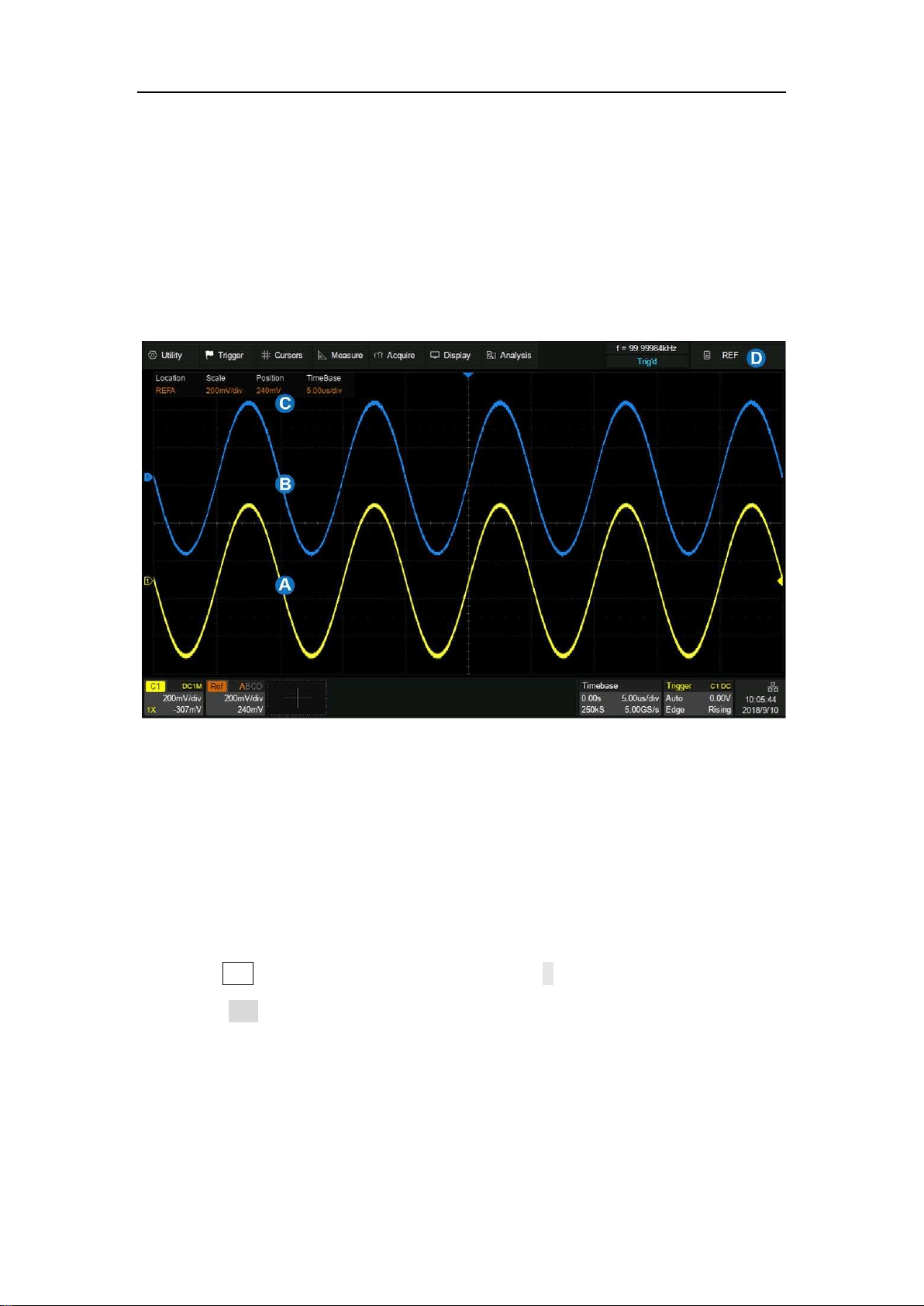
SDS5000X Series Digital Oscilloscope User Manual
167 / 236 W W W. S I G L E N T. C O M
20 Reference
Data from analog channels or math can be saved to the reference locations
(REFA/REFB/REFC/REFD) in the built-in nonvolatile memory. The saved
reference waveform can be recalled to be compared with current waveform.
A. Channel waveform
B. Reference waveform
C. Reference vertical and horizontal information display area
D. Reference dialog box, hidden in this figure
Press the Ref button on the front panel, or touch + in the descriptor box region
and select Ref to recall the ref dialog box.
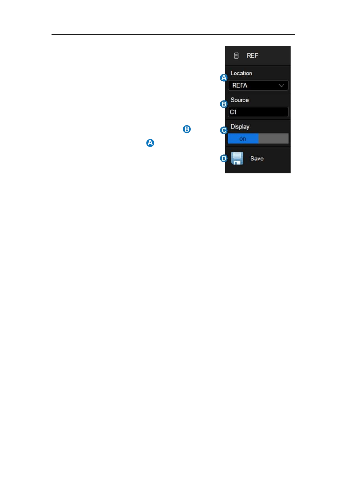
SDS5000X Series Digital Oscilloscope User Manual
168 / 236 W W W. S I G L E N T. C O M
A. Select the location of the reference
(REFA/REFB/REFC/REFD)
B. Select the source (C1~C4 and MATH)
C. Enable/disable Display of the reference
waveform
D. Save the specified waveform in to the
specified location in
Adjust the Reference Waveform
Set the vertical position of the reference waveform by the offset knob shared by
Decode, Digital, Math and Ref on the front panel, and set the vertical scale of
the reference waveform by the scale knob.
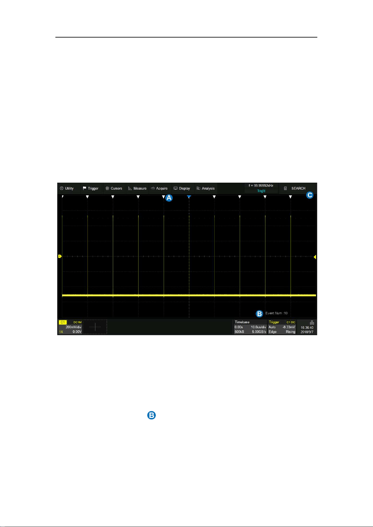
SDS5000X Series Digital Oscilloscope User Manual
169 / 236 W W W. S I G L E N T. C O M
21 Search
The SDS5000X can search for the specified events in a frame. Location of the
events are displayed with white triangle indicators. In YT mode or Roll mode
with the acquisition stopped, up to 1000 events is supported. In Roll mode with
acquisition in run, the number of search events is unlimited. The waveform can
be zoomed when the search function is enabled.
A. Search event indicator, marking the time point of an event
B. Total number of events marked on the display
C. Search dialog box, hidden in this example
In the stop state, the area shows the index of current event /total number
of events. The current event is the one in the center of the display.
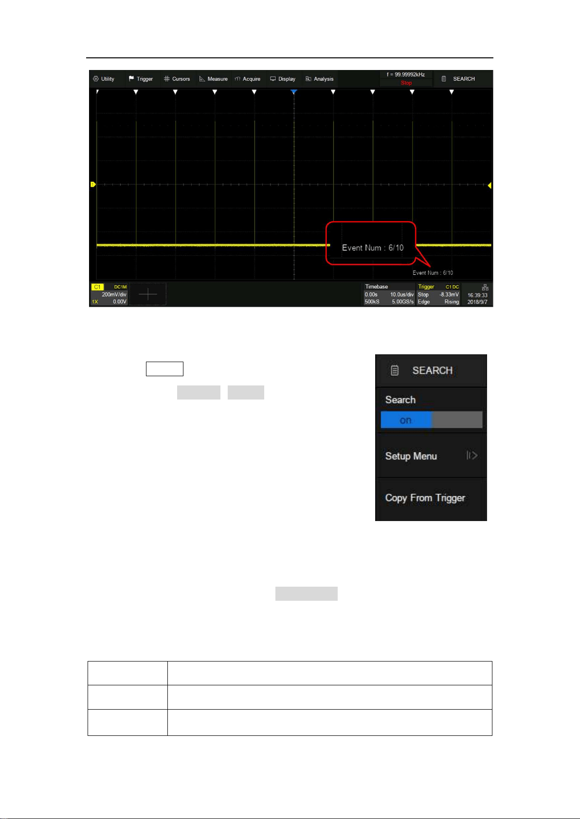
SDS5000X Series Digital Oscilloscope User Manual
170 / 236 W W W. S I G L E N T. C O M
Press the Search button on the front panel or
touch the menu Analysis>Search to recall the
search dialog box and turn on it.
Setup Menu
Select and set the search type in the Setup Menu. The SDS5000X provides five
search conditions: Edge, Slope, Pulse, Interval and Runt.
Search Type
Setup Description
Edge
Slope: Rising, Falling, Either
Slope
Slope: Rising, Falling

SDS5000X Series Digital Oscilloscope User Manual
171 / 236 W W W. S I G L E N T. C O M
Limit Range setting is available
Pulse
Polarity: Positive, Negative
Limit Range setting is available
Interval
Slope: Rising, Falling
Limit Range setting is available
Runt
Polarity: Positive, Negative
Limit Range setting is available
Search setup is similar to the corresponding trigger type. See the sections
“Edge Trigger”, “Slope Trigger”, ”Pulse Trigger”, ”Interval Trigger” and ”Runt
Trigger” for details.
Copy
The SDS5000X supports replication between search settings and trigger
settings.
Copy from Trigger: Synchronize the current trigger settings to the search
settings.
Copy to Trigger: Synchronize the current search settings to the trigger
settings.
Cancel Copy: Cancel the last synchronization and restore the settings
before it.
Note: When performing copy from trigger, if the trigger type is not supported by
search, the operation is invalid.
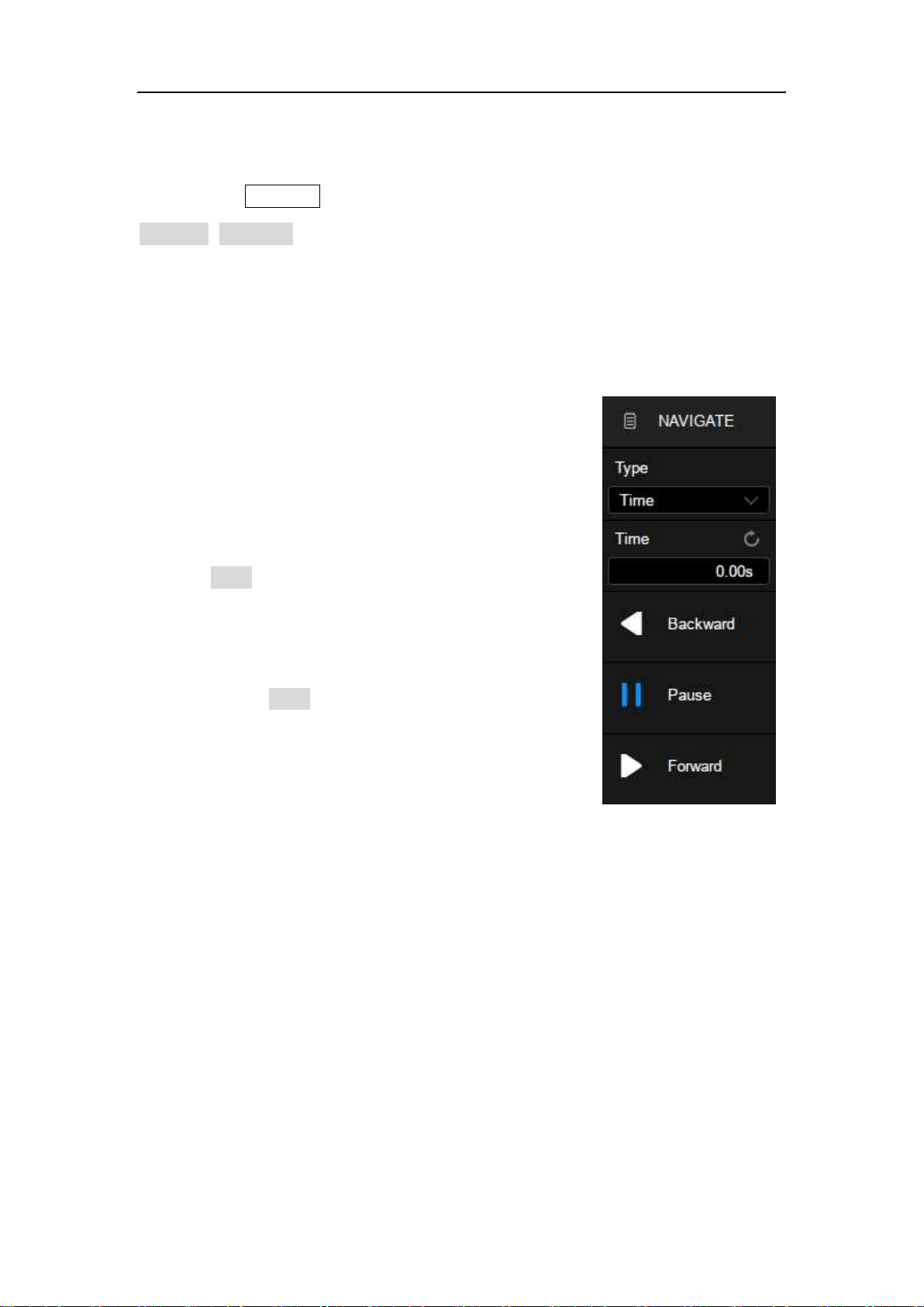
SDS5000X Series Digital Oscilloscope User Manual
172 / 236 W W W. S I G L E N T. C O M
22 Navigate
Press the Navigate button on the front panel or touch the menu
Analysis>Navigate to recall the navigate dialog box. The SDS5000X provides
three navigate types: Search Event, Time and History Frame.
Navigate by Time
The oscilloscope automatically adjusts the
trigger delay according to the direction set by
the user.
Touch Type in the navigate dialog box to
select the navigate type as “Time”. There are
two ways to navigate by time:
Touch the Time area to set the time value
by the universal knob or the virtual keypad.
Press the navigation buttons ◀■▶ on the
front panel to play backward, stop, or play
forward the waveform. Press the ◀ or ▶
buttons multiple times to speed up the
playing. Three speed levels are supported:
Low Speed, Medium Speed and High
Speed.
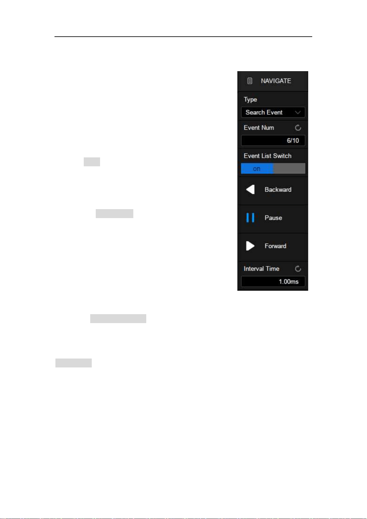
SDS5000X Series Digital Oscilloscope User Manual
173 / 236 W W W. S I G L E N T. C O M
Navigate by Search Event
When the Search function is turned on and the
acquisition is stopped, Navigate is usable to
find search events (see the chapter "Search"
for search function).
Touch Type in the navigate dialog box to
select the navigate type as “Search Event”.
Touch the Event Num area to set the event
number by the universal knob or the virtual
keypad. Press the navigation buttons ◀ or ▶
on the front panel to go to the previous or next
search event.
Touch the Event List Switch area to turn on or off the list. The list contains time
labels for each event. Touching a row in the list automatically jumps to the
corresponding event. This operation is equivalent to specifying an event in the
Event Num area.
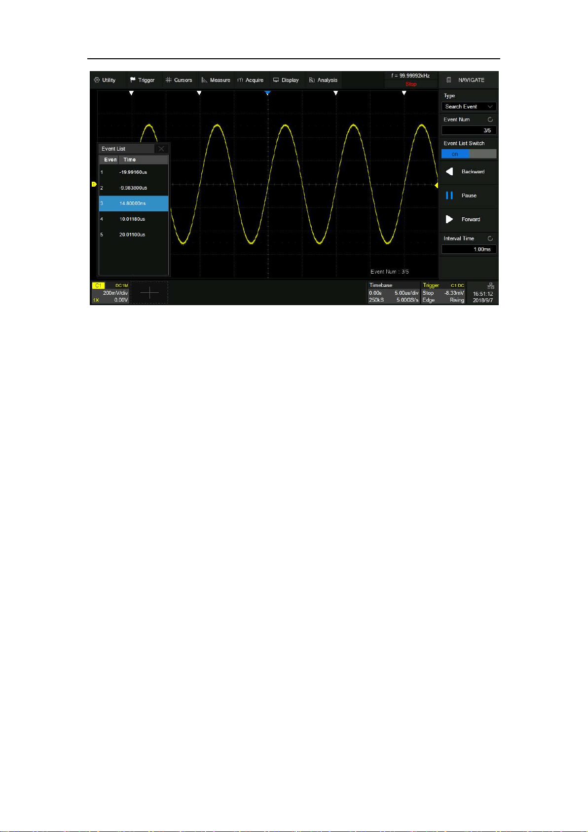
SDS5000X Series Digital Oscilloscope User Manual
174 / 236 W W W. S I G L E N T. C O M
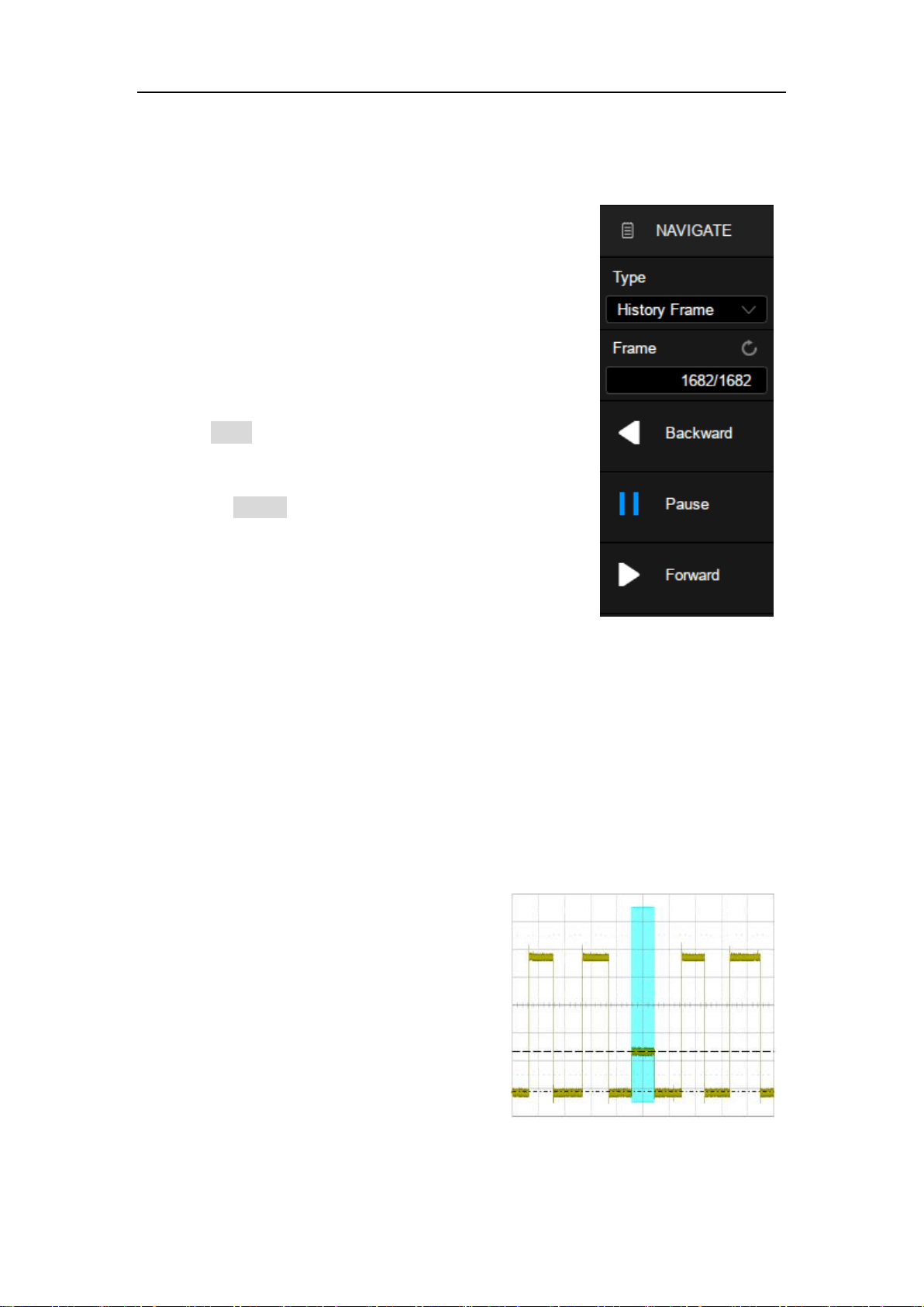
SDS5000X Series Digital Oscilloscope User Manual
175 / 236 W W W. S I G L E N T. C O M
Navigate by History Frame
When the history function is turned on,
Navigate can be used to play history frames
(see the chapter "History" for details of history
function).
Touch Type in the navigate dialog box to
select the navigate type as “History Frame”.
Touch the Frame area to set the frame number
by the universal knob or the virtual keypad.
Press the navigation buttons ◀ ■ ▶ on the
front panel to play backward, stop, or play
forward.
The following is an example of an occasional runt signal to demonstrate how to
quickly locate and find events of interest by using the combination of Search
and Navigate:
The input signal is a 5 V periodic
square wave, in which every 200
ms there is a dwarf pulse with a
height of 1/3 of the normal
amplitude:
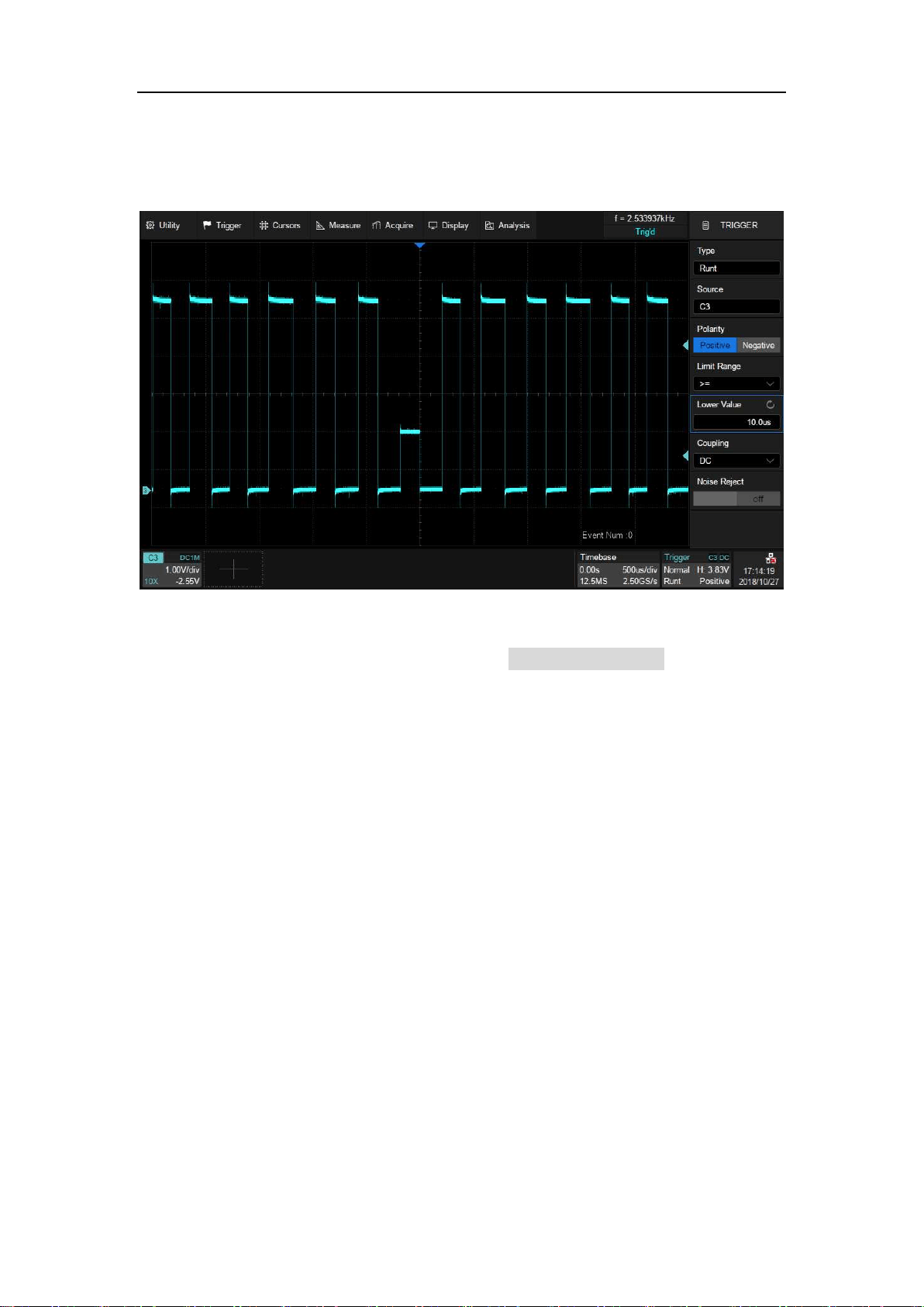
SDS5000X Series Digital Oscilloscope User Manual
176 / 236 W W W. S I G L E N T. C O M
First, set the trigger type to Runt to trigger on the dwarf pulse. See the section
“Runt Trigger” for details.
Then turn on Search function and operate Copy from Trigger in the search
dialog box so that the oscilloscope searches for the dwarf pulses according to
the same setting as the trigger.
Set the horizontal scale to 100 ms/div, then 5 markers with ~200 ms interval is
shown on the display, indicating that a total of 5 dwarf pulses were found in the
full screen of 1 second time range:
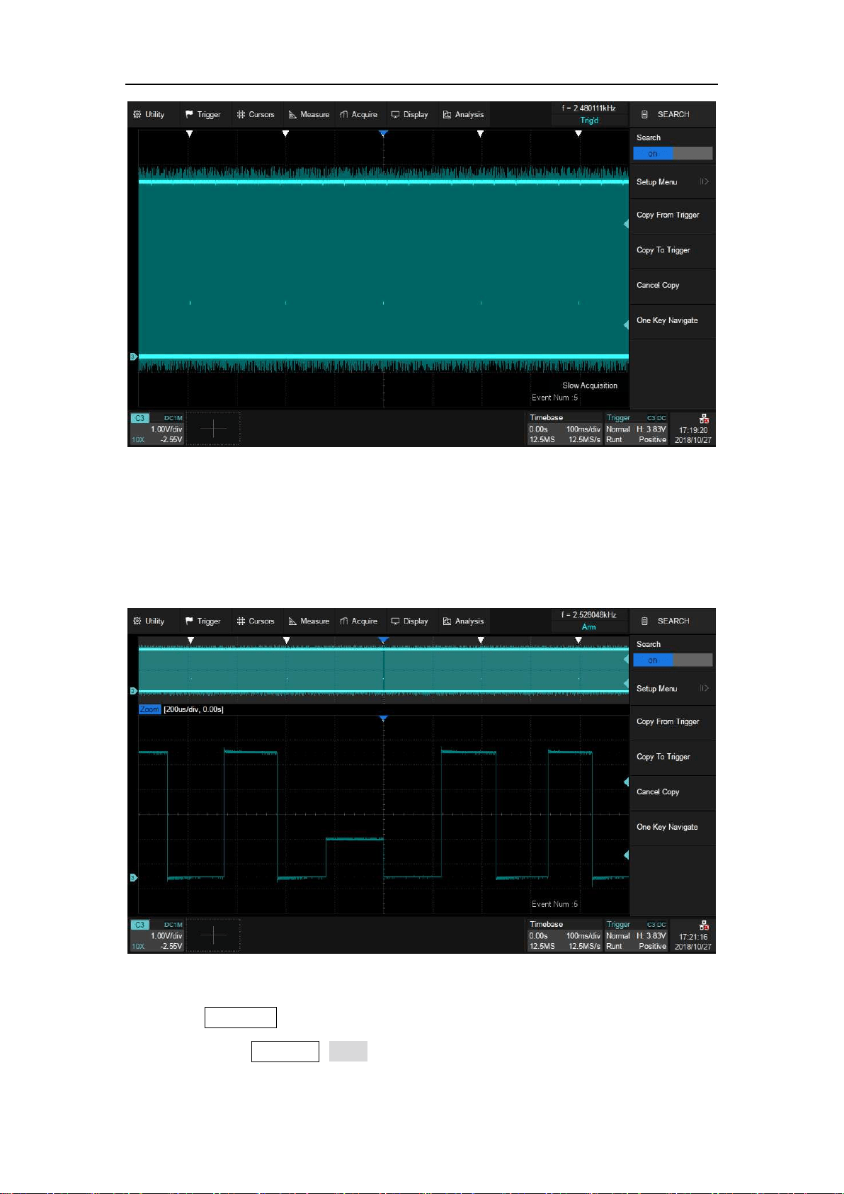
SDS5000X Series Digital Oscilloscope User Manual
177 / 236 W W W. S I G L E N T. C O M
Turn on Zoom function to observe the full view of the frame and the detail of the
third dwarf pulse at the same time:
Press the Run/Stop button on the front panel to stop the acquisition, and then
follow the steps Navigate>Type to select “Search Event”. The following figure
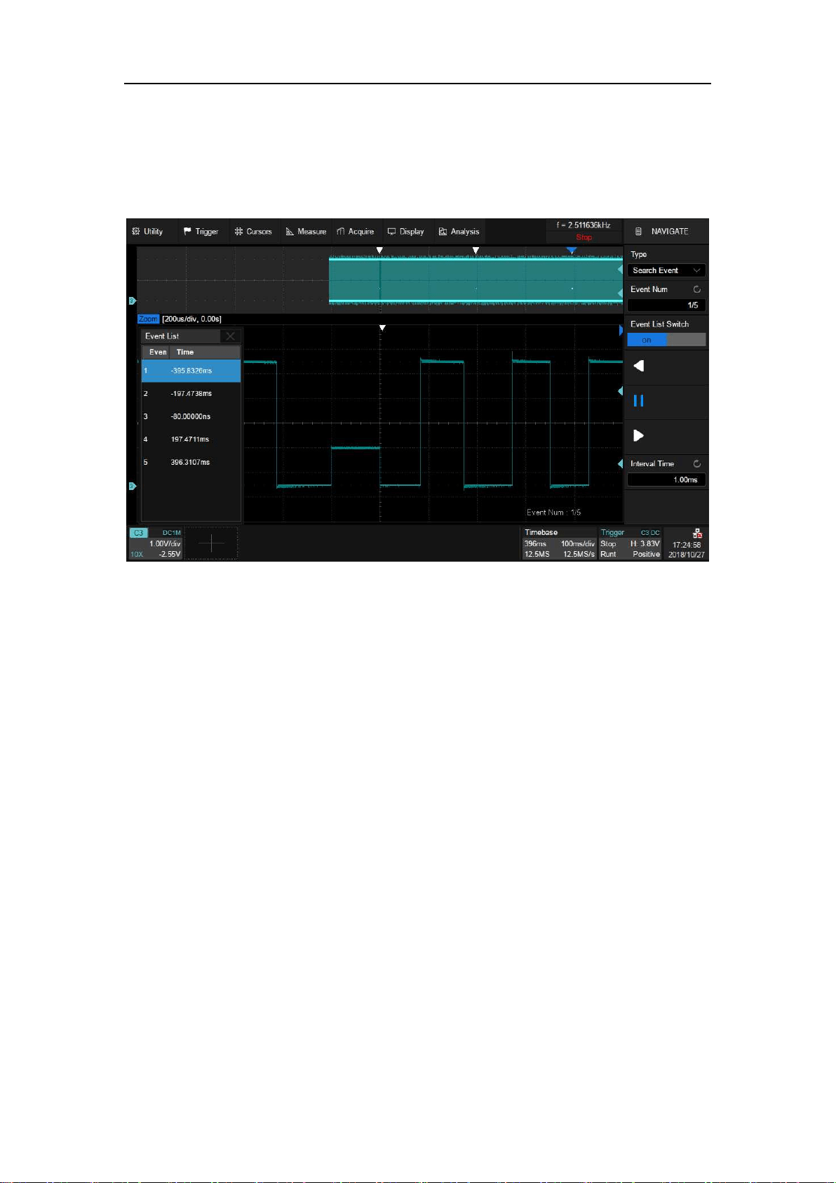
SDS5000X Series Digital Oscilloscope User Manual
178 / 236 W W W. S I G L E N T. C O M
shows the first dwarf pulse. In this example the list is enabled and time labels
of each event are shown in the list.
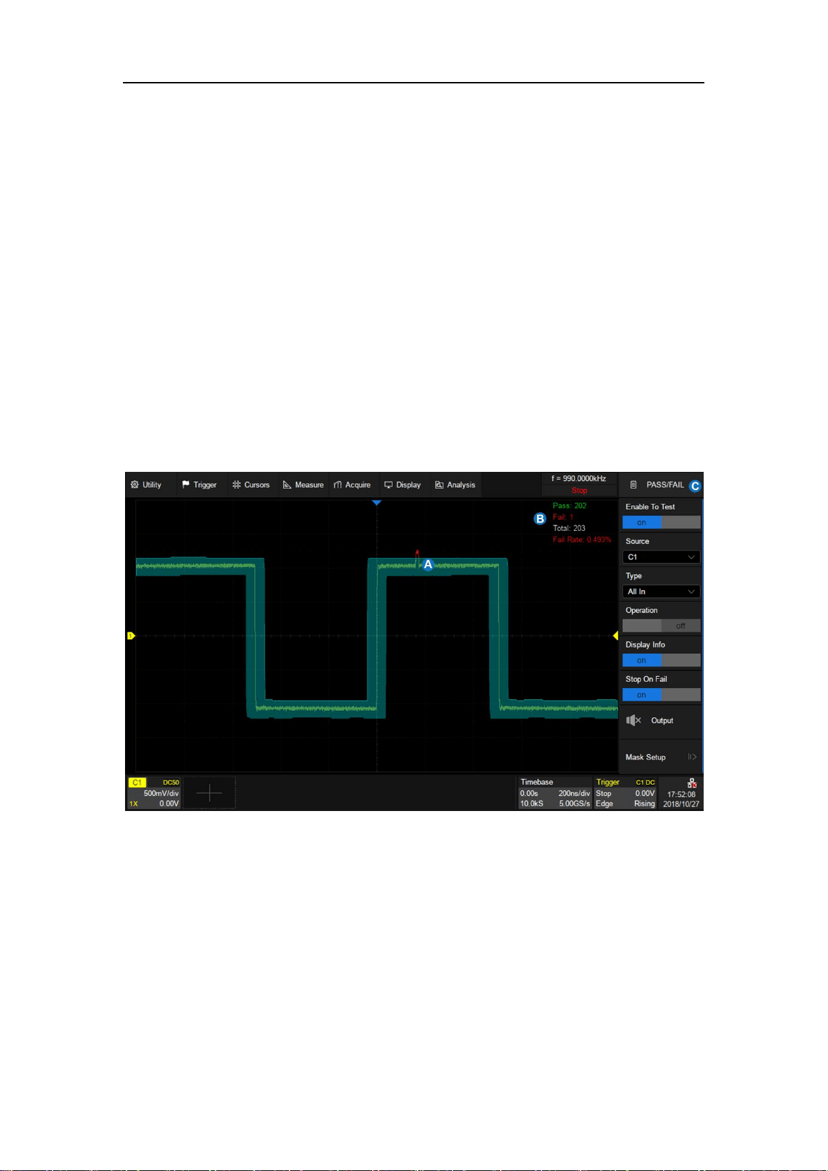
SDS5000X Series Digital Oscilloscope User Manual
179 / 236 W W W. S I G L E N T. C O M
23 Pass/Fail
23.1 Overview
Users can create masks and define the rule used to evaluate Pass/Fail
operations. An event violating the rule is defined as a failure and a pulse can
be generated from the "Aux Out" port on the back panel. This is very useful to
find and quantify anomalies in production tests or similar batch measurements.
When Pass/Fail is enabled, the signal output from the Aux Out is automatically
switched to Pass/Fail pulse.
A. Mask area in green. Any dot violating the rule is highlighted in red,
instead of the normal waveform color.
B. Pass/Fail information display area, including count of the passed
frames, failed frames, total frames, and the fail rate.
C. Dialog box
SDS5000X Series Digital Oscilloscope User Manual
180 / 236 W W W. S I G L E N T. C O M
Perform Analysis>Pass/Fail to open the Pass/Fail dialog box:
A. Turn on/off the test
B. Select the source(C1~C4)
C. Select the rule(All In, All Out, Any In
and Any Out)
D. Turn on/off the Pass/Fail operation.
Turning off the operation when the
test is in progress will stop the test
immediately, and the counters in the
information display area will stop.
Turn on the operation again re-starts
the test and all the counters are
cleared. Pressing the Clear Sweeps
button on the front panel is equivalent.
E. Turn on/off the information display
F. Turn on/off “Stop on Fail”. When it is
"on", the oscilloscope stops the
acquisition once it detects a failure
G. Turn on/off the sound prompt when a
failure occurs.
H. Set the mask
SDS5000X Series Digital Oscilloscope User Manual
181 / 236 W W W. S I G L E N T. C O M
23.2 Mask Setup
Touch Mask Setup in the Pass/Fail dialog box to
set the mask:
A. Create mask automatically according to
the waveform
B. Create custom mask using the Mask
Editor tool
C. Specify the location of the mask to be
loaded
D. Load the mask from the location specified
at
E. Return to previous menu
SDS5000X Series Digital Oscilloscope User Manual
182 / 236 W W W. S I G L E N T. C O M
23.2.1 Create Mask
The mask can be created based on an existed waveform trace.
A. Set the spacing of the mask to the trace in
horizontal, with unit of division
B. Set the spacing of the mask to the trace in
vertical, with unit of division
C. Create the mask based on settings in
and
D. Specify the location of the mask to be
saved
E. Save the mask to the location specified at
F. Return to previous menu
Set the values for Mask X and Mask Y (in divisions of display graticules), and
then perform Create Mask to generate the mask. The horizontal and vertical
adjustment range is 0.04~4.00 div.
SDS5000X Series Digital Oscilloscope User Manual
183 / 236 W W W. S I G L E N T. C O M
X=0.2 div, Y=0.2 div
X=1 div, Y=1 div
Saving and recalling mask files (*.msk) is similar to the operation of setup files,
see the chapter "Save/Recall" for details. Only one mask file is supported to
save when the location is "Internal".
23.2.2 Mask Editor
The Mask Editor is a built-in tool which provides an approach to create custom
masks. Below is its layout:
A. Menu bar
B. Coordinate of the latest touched point on the display
C. Mask edit area, which is equivalent to the grid area. In this example,
a hexagon has been created as a part of the mask
D. Tool bar
E. Coordinate edit area. Set the X ordinate and Y ordinate by the

SDS5000X Series Digital Oscilloscope User Manual
184 / 236 W W W. S I G L E N T. C O M
virtual keypad and then touch the “Input” button the perform the
ordinate update
F. Display or hide coordinate of polygon vertices on the display
G. Exit the tool
Menu bar
There are 2 menus on the menu bar. The File menu includes ordinary file
operations such as:
New: Create a new mask file
Open: Open an existed mask file
Save: Save the current mask file
Exit: Exit the Mask Editor tool
Note: The mask file created by the “Create Mask” cannot be recalled by the
Mask Editor.
The contents of the Edit menu are equivalent to the Tool bar.
Tool bar
Draw: Creates vertices of a polygon by touching the display or entering
values in coordinate edit area
Create Polygon: Creates a polygon based on the drawn vertices by
the operation Draw
Undo
Redo
SDS5000X Series Digital Oscilloscope User Manual
185 / 236 W W W. S I G L E N T. C O M
Insert Point: Inserts a vertex on a selected side
Edit Polygon: Edits a polygon. Vertices, sides and the polygon are all
editable object
Delete Polygon: Deletes selected polygon
To edit a vertex, side or polygon object, firstly select it, and then move it by a
dragging gesture or by entering the desired value in coordinate edit area.
For a side, the value is for its middle point. For a polygon, the ordinate is for its
geometric center.
Select a vertex (point)
Select a side (line segment)
Select a polygon
23.3 Pass/Fail Rule
The Pass/Fail rule is specified at the Type region in the Pass/Fail dialog box.
All In: All data points must be inside the mask to pass the test. Even a

SDS5000X Series Digital Oscilloscope User Manual
186 / 236 W W W. S I G L E N T. C O M
single point outside the mask will cause a failure.
All Out: All data points must be outside the mask to pass the test. Even
a single point inside the mask will cause a failure.
Any In: Any data point inside the mask will be recognized as pass. All
data points outside the mask will cause a failure.
Any Out: Any data point outside the mask will be recognized as pass.
All data points inside the mask will cause a failure.
23.4 Operation
Touch Operation to start/stop the test. Stopping a test in progress and restart
the test will clear the count of the passed frames, failed frames, total frames,
and the fail rate. Pressing the Clear Sweeps button on the front panel can also
clear the count information.
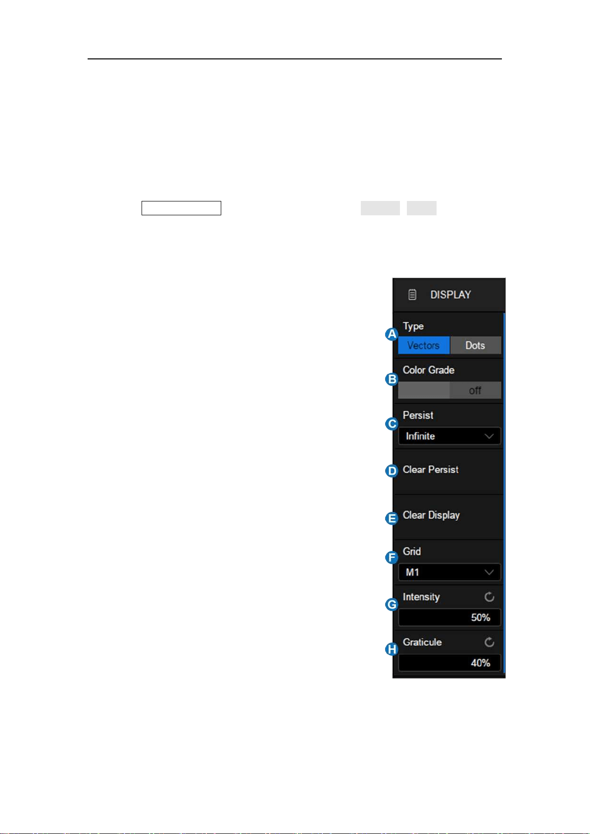
SDS5000X Series Digital Oscilloscope User Manual
187 / 236 W W W. S I G L E N T. C O M
24 Display
Display settings include display type of waveform, color, persistence, grid type,
trace brightness, graticule brightness etc.
Press the Display/Persist button, or touch the menu Display>Menu to recall the
display dialog box.
A. Switch the waveform display type to
Vectors (line display) or Dots
B. Turn on or off color grade
C. Set persist
D. Clear persist
E. Clear display. The operation clears all
waveforms displaying on the screen
and clear persist
F. Select the grid type (M1, M2 and M3)
G. Set the trace intensity (0~100%)
H. Set the graticule brightness (0~100%)
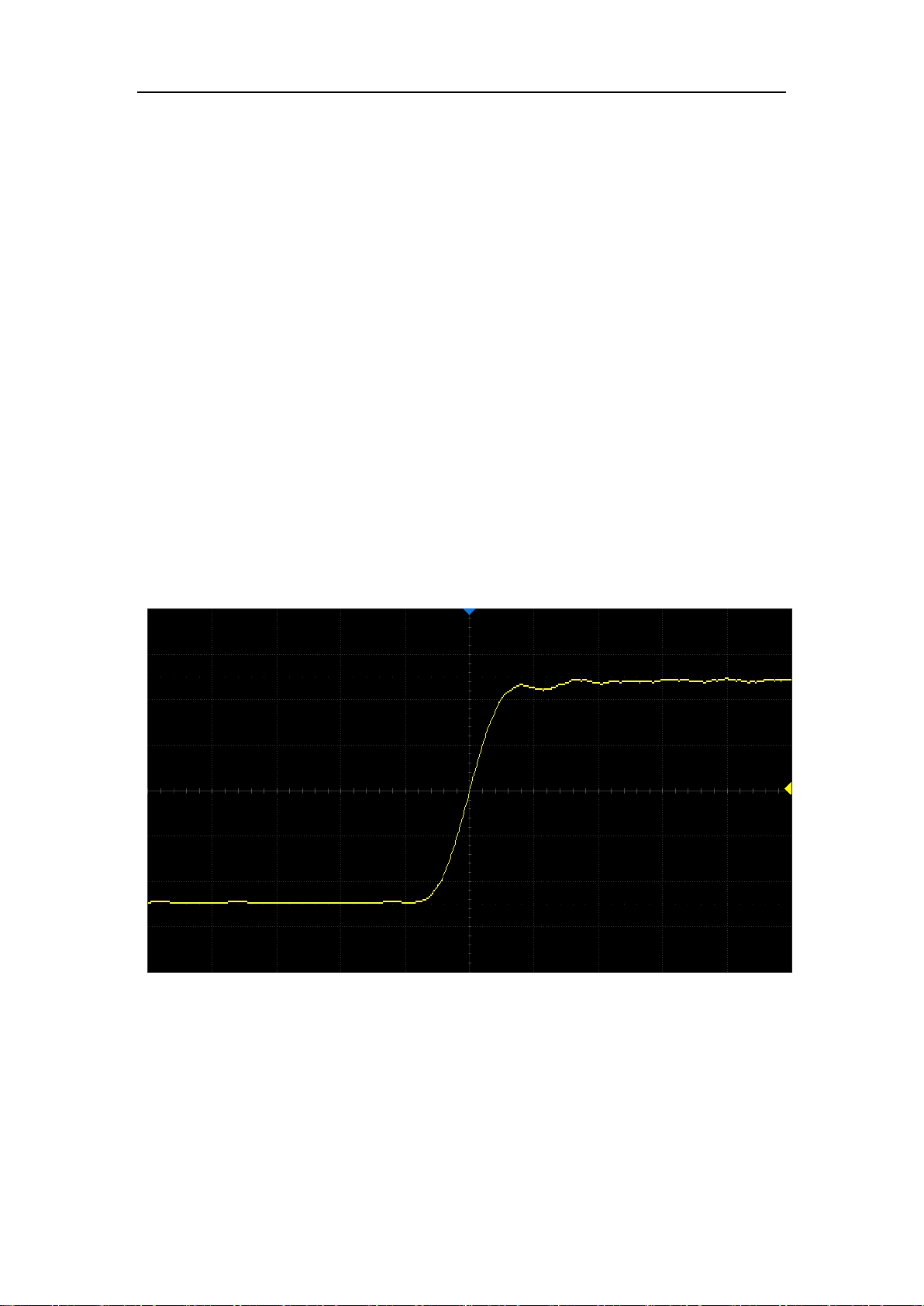
SDS5000X Series Digital Oscilloscope User Manual
188 / 236 W W W. S I G L E N T. C O M
Display Type
There is no difference between the vector and dot display types when the
number of samples of a frame is greater than 1000. When the sample number
is below 1000, there are some differences.
Vectors: The samples are connected by lines (i.e. interpolated) and
displayed. The interpolation methods include linear interpolation and
sin(x)/x interpolation. See the section of "Acquisition Setup" for details of
interpolation.
Dots: Displays the raw samples directly.
Vector Display
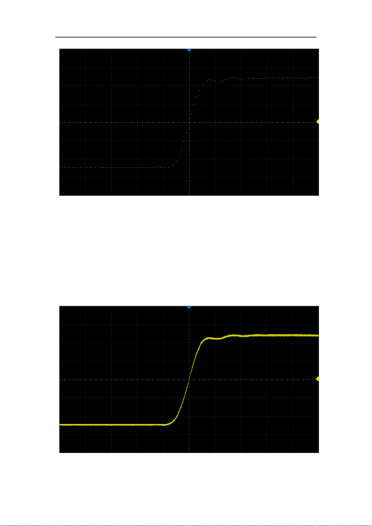
SDS5000X Series Digital Oscilloscope User Manual
189 / 236 W W W. S I G L E N T. C O M
Dot Display
Note: In the Run state, due to the high waveform update rate of the oscilloscope,
the waveform displayed is the superposition of multiple frames. Therefore, what
is seen using the dots display is not the discrete sampling points, but the display
effect similar to equivalent sampling. Stop the acquisition to view the original
samples of each frame separately.
Dots display in Run state
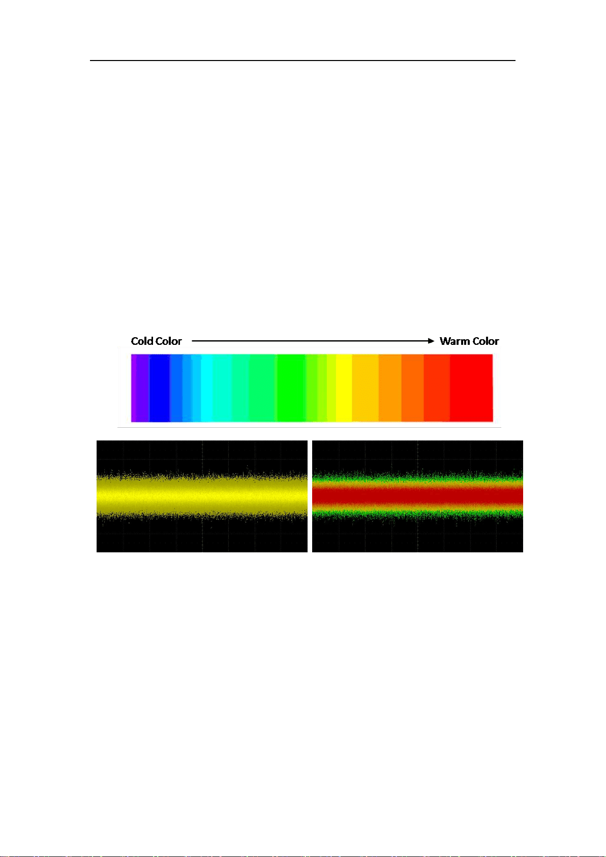
SDS5000X Series Digital Oscilloscope User Manual
190 / 236 W W W. S I G L E N T. C O M
Color Grade
Color grade uses color temperature to map the probability of the waveforms.
The greater the probability that the waveform appears in a pixel, the warmer
the color of the pixel. The smaller probability, the colder the color temperature
of that pixel.
The picture below shows the change of color from cold to warm.
Color grade On
Color grade Off
Set Persist
With persistence, the oscilloscope updates the display with new acquisitions
but does not erase the results of previous acquisitions in specified period. All
previous acquisitions are displayed with reduced intensity. New acquisitions are
shown in their normal color with normal intensity. In combination with
SDS5000X's high waveform update rate and persist function, in some cases
SDS5000X Series Digital Oscilloscope User Manual
191 / 236 W W W. S I G L E N T. C O M
anomalies in the waveform can be found in short time without complex trigger
settings to improve test efficiency. Below is an example to display glitches in a
data sequence with infinite persistence.
When the display dialog box and persist are off, double pressing the
Display/Persist button on the front panel can quickly turn on persist.
Touch Persist in the display dialog box to set the persistence time.
Off: Turn off persist.
Variable persist time (1s, 5s, 10s, 30s): Choose different persist
times. The oscilloscope updates with the new acquired waveform
display. Acquired waveforms will be cleared after the corresponding
time has expired.
Infinite: Select “Infinite”, previous acquisitions will never be erased
until a Clear Display or Clear Sweeps operation is performed.
SDS5000X Series Digital Oscilloscope User Manual
192 / 236 W W W. S I G L E N T. C O M
Set Grid
M1: Display 8*10 grid
M2: Display 2*2 grid
M3: Display without grid
M1 Mode
M2 Mode

SDS5000X Series Digital Oscilloscope User Manual
193 / 236 W W W. S I G L E N T. C O M
M3 Mode
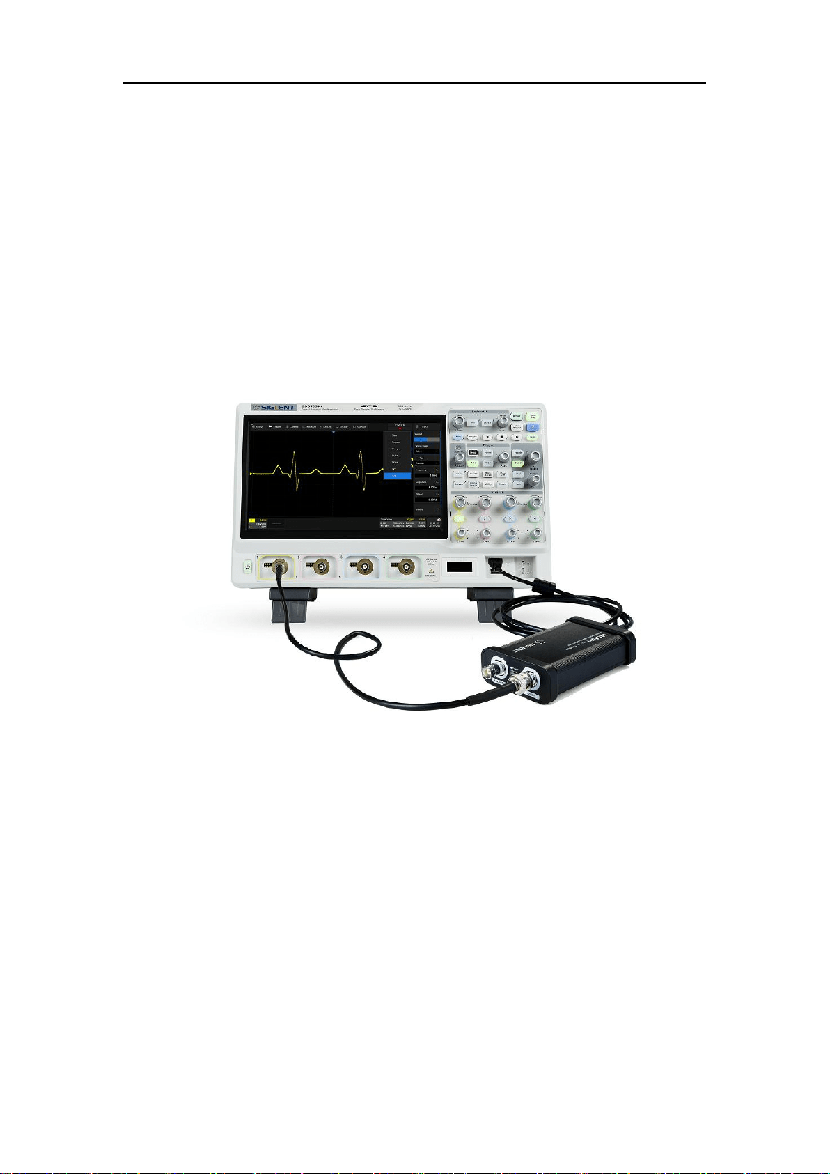
SDS5000X Series Digital Oscilloscope User Manual
194 / 236 W W W. S I G L E N T. C O M
25 Arbitrary Waveform Generator
25.1 Overview
The SDS5000X supports arbitrary waveform/function generation by
incorporating an external USB Arbitrary Waveform Generator accessary
combined with the software activation using option SDS-5000X-FG.
The AWG functions include:
6 basic waveforms: Sine, Square, Ramp, Pulse, Noise and DC
45 built-in and 2 custom arbitrary waveforms
Output frequency up to 25 MHz
-3 V ~ +3 V output amplitude range
Refer to the data sheet for the detailed specifications of the AWG.
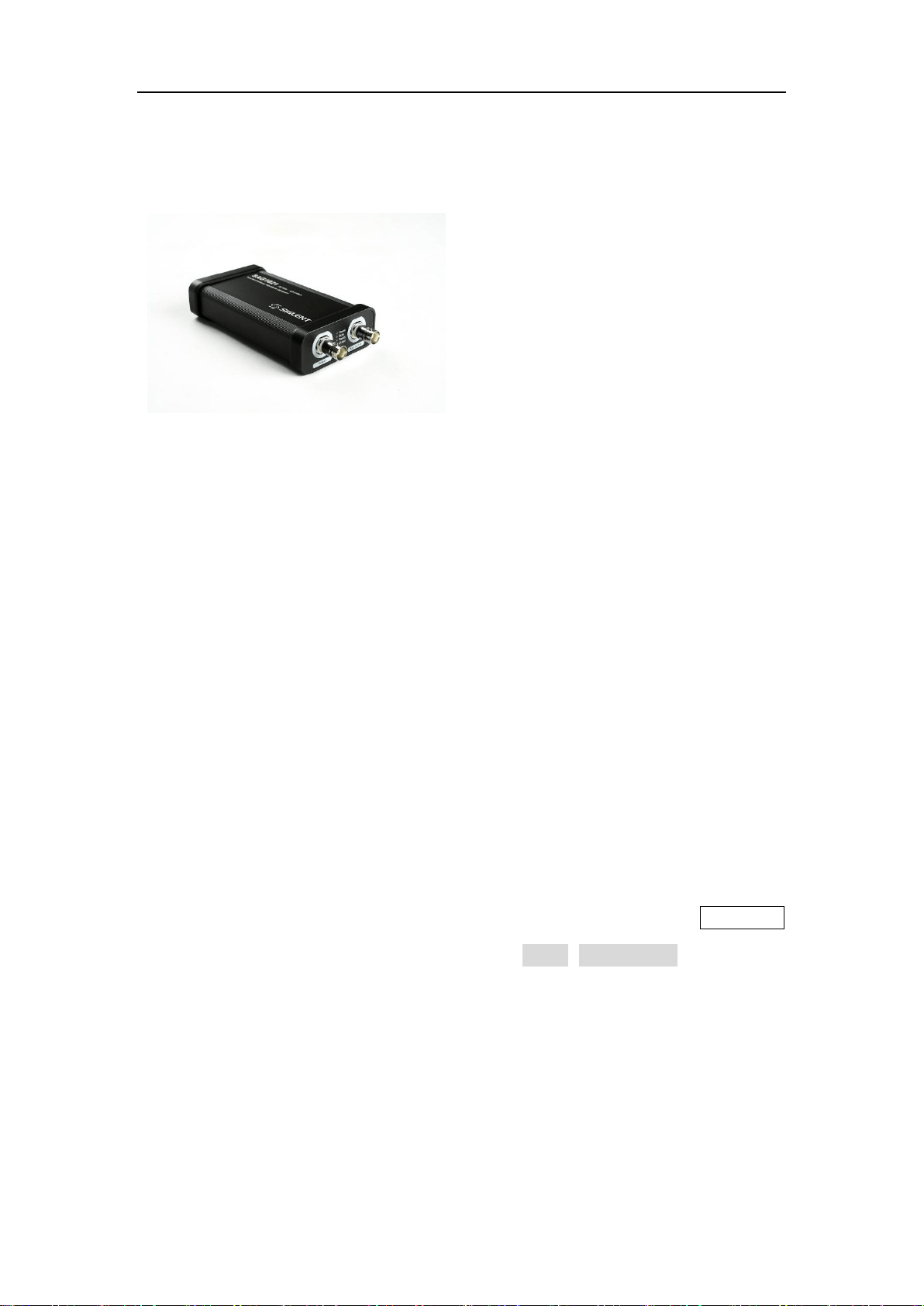
SDS5000X Series Digital Oscilloscope User Manual
195 / 236 W W W. S I G L E N T. C O M
SAG1021 Function/Arbitrary Waveform Generator Module
The SAG1021 function/arbitrary
wave generator module is capable of
generating variant waveforms with
frequency up to 25 MHz and
amplitude up to ±3 V. Users can
edit and import arbitrary waveforms
using the SIGLENT EasyWave
software or import edited waveforms
through a U disk.
Hardware Connection: Connect the SAG1021 to any USB host port of
SDS5000X using a standard USB cable.
SDS-5000X-FG Option
For the installation of the SDS-5000X-FG option, please refer to the section
"Install Option".
The oscilloscope interface will prompt "AWG device detected" after the
hardware connection with the SAG1021 is established. Press the WaveGen
button on the front panel, or touch the menu Utility>AWG Menu to recall the
AWG dialog box.
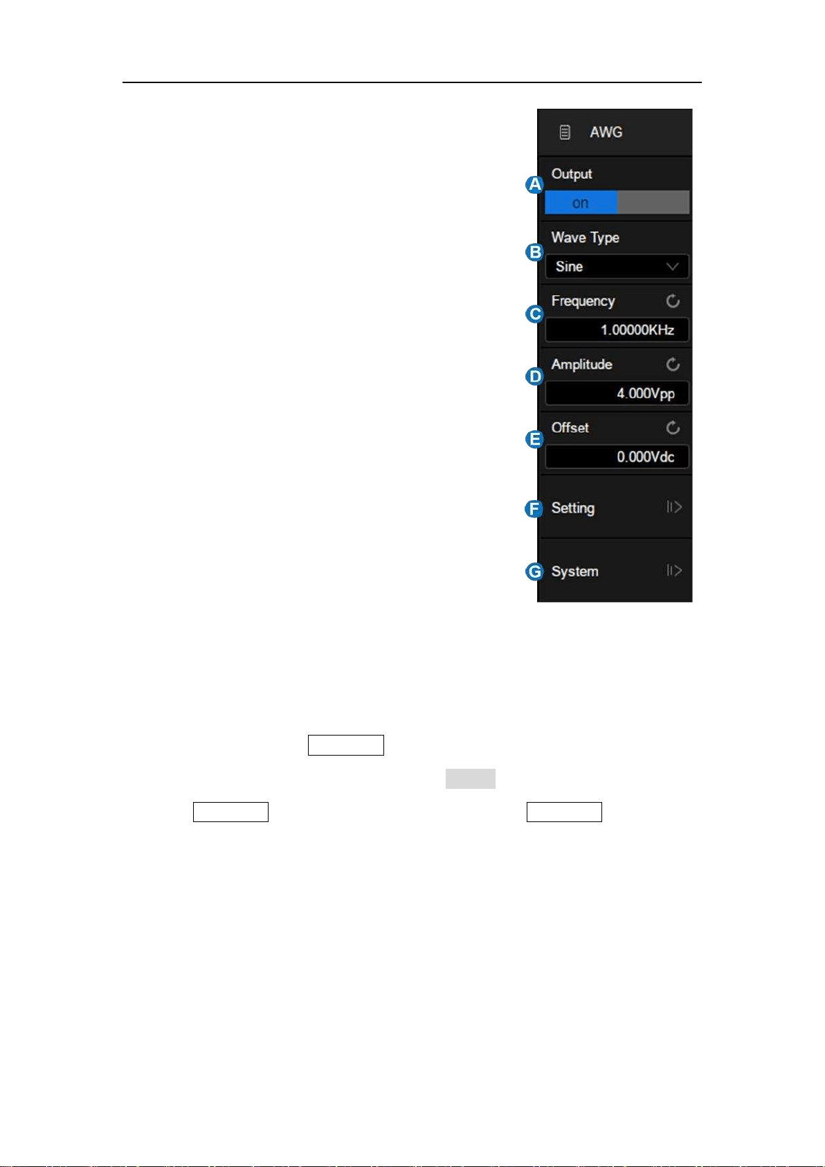
SDS5000X Series Digital Oscilloscope User Manual
196 / 236 W W W. S I G L E N T. C O M
A. Turn on/off the output of AWG
B. Select the waveform type (Sine, Square,
Ramp, Pulse, Noise, DC and Arb)
C. Set the frequency
D. Set the amplitude
E. Set the offset
F. Other AWG settings: output load,
overvoltage protection and so on.
G. SAG1021 system information and
firmware upgrade
25.2 Output
For safety, pressing the WaveGen button does not automatically turn on the
output of AWG. To turn on the output, touch Output in the AWG dialog box after
pressing WaveGen. When the output is enabled, the WaveGen button lights
up.
25.3 Wave Type
The AWG function provides six standard waveforms and multiple arbitrary
waveforms. The standard waveforms are Sine, Square, Ramp, Pulse, Noise
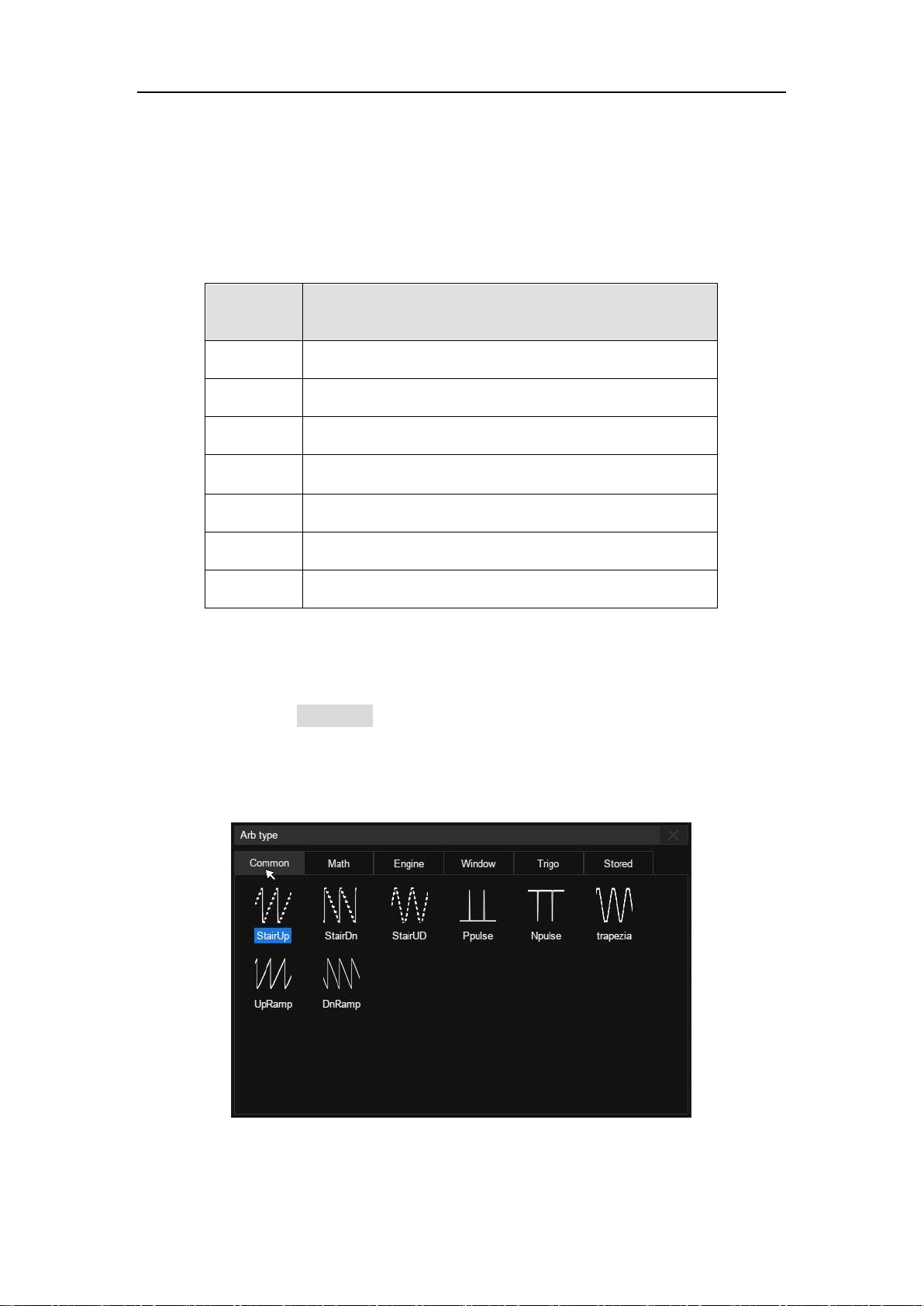
SDS5000X Series Digital Oscilloscope User Manual
197 / 236 W W W. S I G L E N T. C O M
and DC.
The following table shows all waveform types and corresponding parameters.
Wave
Type
Parameters
Sine
Frequency, Amplitude, Offset
Square
Frequency, Amplitude, Offset, Duty
Ramp
Frequency, Amplitude, Offset, Symmetry
Pulse
Frequency, Amplitude, Offset, Duty
DC
Offset
Noise
Stdev, Mean
Arb
Frequency, Amplitude, Offset, Arb Type
The Arbitrary waveforms consists of two types: built-in waveforms and stored
waveforms. Touch Arb Type in the AWG dialog box, and select the arbitrary in
the pop-up window:
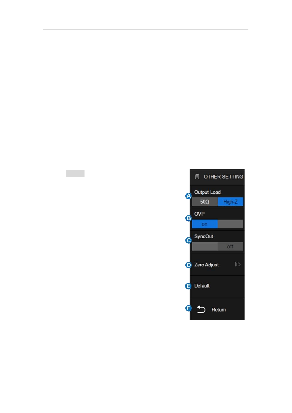
SDS5000X Series Digital Oscilloscope User Manual
198 / 236 W W W. S I G L E N T. C O M
There are 6 tabs in the window. Under each tab a catalog of waveforms are
listed. Built-in waveforms are stored in Common, Math, Engine, Window, and
Trigo. Stored waveforms are located in the Stored menu.
Users can edit arbitrary waveforms using SIGLENT EasyWave PC software,
and send the stored waveforms to the instrument through the remote interface,
or import the stored waveforms through a U disk.
25.4 Other Setting
Touch Setting in the AWG dialog box to recall
"Other Setting" dialog box:
A. Select the output load
B. Turn on/off the OVP (Over Voltage
Protection)
C. Turn on/off the sync output
D. Do zero adjust
E. Set to default
F. Return to previous menu
Output Load
The selected output load value must match the load impedance. Otherwise, the
amplitude and offset of the output waveform of AWG will be incorrect.

SDS5000X Series Digital Oscilloscope User Manual
199 / 236 W W W. S I G L E N T. C O M
OVP
When OVP is enabled, the output will be turned off automatically once the
protection condition is met. The protection condition is when the absolute value
on the output port is higher than 4 V ± 0.5 V). At the same time, a warning
message is displayed.
Sync Output
When the Sync Output is turned on, the Aux In/Out port of AWG outputs a
CMOS signal with the same frequency as the basic waveform (except Noise
and DC) and arbitrary waveform. The maximum supported frequency is 10 MHz.
Zero Adjust
The output zero error of the AWG can be calibrated by using auto mode or
manual mode. The object of the Zero Adjust is: when AWG outputs 0 V DC
signal, the measured mean value of the corresponding channel is within ±1
mV.
Auto Steps: In this mode the adjustment can only be performed with CH1
of the oscilloscope. Connect the output of AWG to CH1 of the oscilloscope,
press Auto, and the AWG will starts to automatic adjust. The scope will
display “Zero adjust completed!” when the adjustment is done.
Manual Steps: The AWG can be manually calibrated through any channel
on the oscilloscope. Take CH2 as an example:
1. Connect the output of AWG to CH2, open CH2, set it to DC coupling,
turn on bandwidth limit, and set the probe attenuation to 1X.
SDS5000X Series Digital Oscilloscope User Manual
200 / 236 W W W. S I G L E N T. C O M
2. Set the vertical scale of CH2 to a small scale such as 1 mV/div. Turn
on measure and set the parameter to Mean of CH2.
3. Press Manual and rotate the universal knob to adjust the compensation
value, until the mean value of CH2 is within ± 1 mV, and then press
Save.
25.5 System
Device Info – includes Model, Serial Number, Firmware Version and Hardware
Version of the AWG module.
Upgrade
The firmware here refers to the firmware of the SAG1021 module. The
SDS5000X supports firmware and configuration file upgrades for the SAG1021
via a U disk. Follow the steps below:
SDS5000X Series Digital Oscilloscope User Manual
2 01 / 236 W W W. S I G L E N T. C O M
1. Copy the upgrade file (*.ADS) to the U disk.
2. Insert the U disk to one of the USB host ports of the oscilloscope.
3. Touch Browse… to select the path of the upgrade file. See the chapter
"Save/Recall" for the detailed operation.
4. Touch Upgrade to start the upgrade progress. A progress bar shows
the percentage finished.
5. After the upgrade, the SAG1021 will be removed from the system, and
the oscilloscope prompts "Upgrade completed. Please reconnect the
AWG device."
6. Enter System dialog box again to check if the upgraded hardware
version number is consistent with the target version.
Warning:Don't cut off the power during the upgrade!

SDS5000X Series Digital Oscilloscope User Manual
202 / 236 W W W. S I G L E N T. C O M
26 Save/Recall
The SDS5000X supports saving setups, reference waveforms, screen shots,
and waveform data files to internal storage or external USB storage devices
(e.g. U disk). Saved setups and reference waveforms can be recalled as
needed.
26.1 Save Type
SDS5000X supports save types: Setup, Reference, Image (*.bmp/*.jpg/*.png),
Waveform Data (binary/csv/matlab), and Calibration Files. It also supports
saving the current setup as default setting.
Here are brief descriptions of save types:
Setup
The default save type of the oscilloscope. The setup is saved into internal or
external memory with the *.xml file extension. Up to 10 setup files can be stored
in the internal memory (No.1 ~ No.10).
Reference
The reference waveform data are saved to external memory with the *.ref file
extension. The saved file contains the reference waveform data and its setup
information such as the vertical scale, vertical position and timebase.
BMP
Saves the screen shot to external memory in *.bmp format.

SDS5000X Series Digital Oscilloscope User Manual
203 / 236 W W W. S I G L E N T. C O M
JPG
Saves the screen shot to external memory in *.jpg format.
PNG
Saves the screen shot to external memory in *.png format.
Binary Data
Saves the waveform data to external memory in binary (*.bin) format.
CSV Data
Saves the waveform data to the external memory in ".csv" format. After
selecting this type, you can touch the Para Switch to determine to include the
scope configuration parameter information (horizontal timebase, vertical scale,
etc..) or not.
Matlab Data
Saves the waveform data to external memory in *.dat format which can be
imported by Matlab directly.
To Default Key
The oscilloscope provides two options for the default setting. When the Default
Type is set to “Factory”, the factory default setting will be recalled by pressing
the Default button on the front panel; When the Default Type is set to “Current”,

SDS5000X Series Digital Oscilloscope User Manual
204 / 236 W W W. S I G L E N T. C O M
the last setting saved by the “To Default Key” operation will be recalled by
pressing the Default button on the front panel.
Cal File
Save the calibration file to external memory in *.cal format.
The following table show the relationship between the save types and
save/recall operations.
Type
Save to
Internal
Save to
External
Recall
Setup
√
√
√
Reference
×
√
√
BMP
×
√
×
JPG
×
√
×
PNG
×
√
×
Binary Data
×
√
×
CSV Data
×
√
×
Matlab Data
×
√
×
Cal File
×
√
√
* Save/Recall only supports saving Reference to external memory. However,
the reference waveform itself can be saved to internal memory. See the chapter
"Reference " for details.
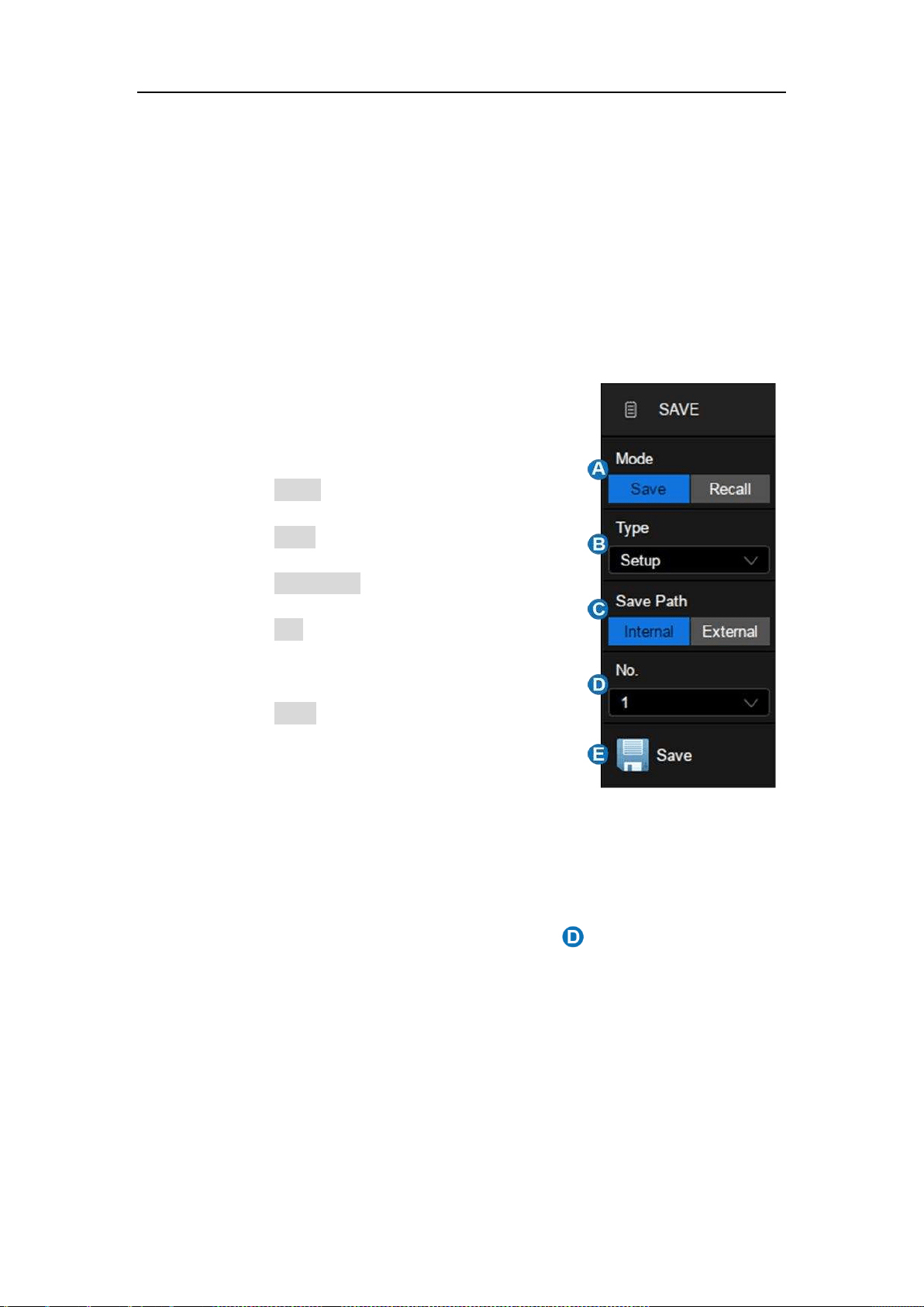
SDS5000X Series Digital Oscilloscope User Manual
205 / 236 W W W. S I G L E N T. C O M
26.2 Internal Save and Recall
"Setup" can be saved/recalled to/from the internal memory. In this section the
save/recall operations of Setup is introduced.
Save oscilloscope setup to internal memory
Follow the steps below:
A. Select Mode as "Save"
B. Select Type as "Setup"
C. Select Save Path as "Internal"
D. Select No. of internal storage locations,
1~10 optional.
E. Touch Save to perform the save operation
A progress bar is shown when the Save operation is in progress. When it is
done, the oscilloscope prompts "Saved to internal file No.X", where X is the
internal storage location index selected in the step .
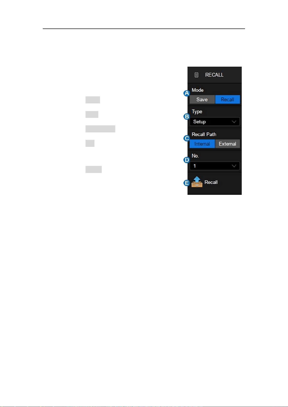
SDS5000X Series Digital Oscilloscope User Manual
206 / 236 W W W. S I G L E N T. C O M
Recall oscilloscope setup from internal memory
Follow the steps below:
A. Select Mode as "Recall"
B. Select Type as "Setup"
C. Select Recall Path as "Internal"
D. Select No. of internal storage locations,
1~10 optional
E. Touch Recall to perform the recall
operation
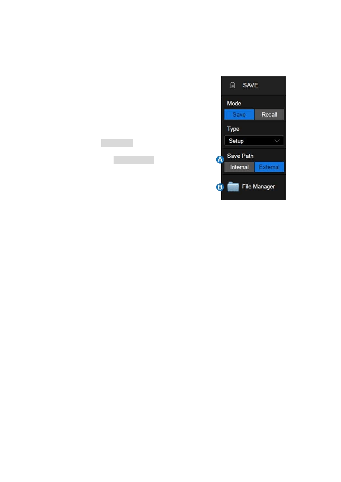
SDS5000X Series Digital Oscilloscope User Manual
207 / 236 W W W. S I G L E N T. C O M
26.3 External Save and Recall
Before performing an external save or recall, make
sure the USB storage device is connected
correctly.
A. Select Save Path as "External"
B. Touch the File Manager and open the file
manager. If the U disk is not properly
connected, the system will prompt "USB
flash drive not detected!"
26.3.1 File manager
The SDS5000X's file manager has similar style and operation with the Windows
operating systems.
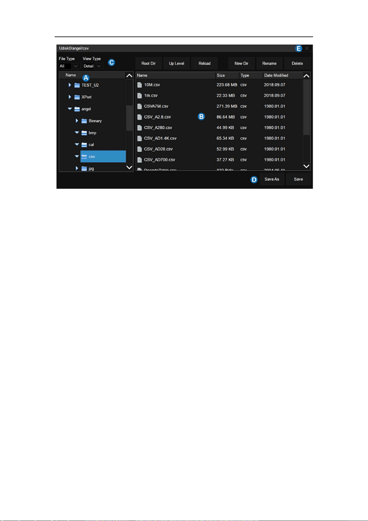
SDS5000X Series Digital Oscilloscope User Manual
208 / 236 W W W. S I G L E N T. C O M
A. Left window
B. Right window
C. Tool bar
D. Save/Recall command bar
E. Close the file manager
Left window: Displays a list of available drives and internal folders.
The selected folder has an icon with blue background.
The triangle tag on the left of the folder indicates that the folder includes
subfolder(s). Clicking the tag expands the folder to show the
subfolder(s) in the left window.
Right window: Displays the files and the subfolders contained in the selected
folder.
Tool bar: Graphical commands for file operations.
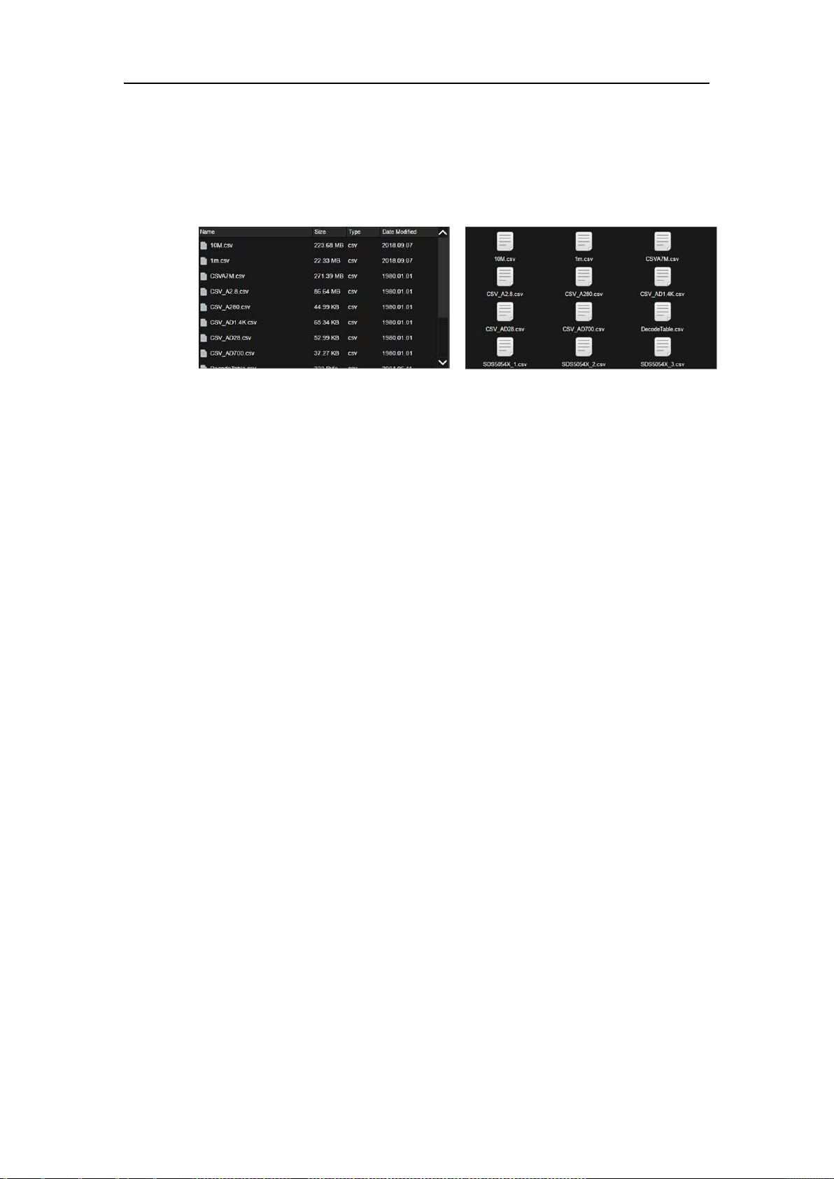
SDS5000X Series Digital Oscilloscope User Manual
209 / 236 W W W. S I G L E N T. C O M
File Type: Specify the file type to display, including All (all types),
*.xml,*.ref,*.bmp,*.jpg,*.png,*.csv,*.dat,*.bin, and*.cal
View Type: Contains two modes of "Detail" and "Icon
Detail View Type
Icon View Type
Root Dir: Jump to root directory quickly
Up Level: Return to upper level folder
Reload: Refresh file manager view
New Dir: Create a new folder under the current path
Rename: Rename the selected file or folder
Delete: Delete the selected file or folder
Save/Recall command bar – Execute the Save/Recall command
Save As: Save as the filename specified by the user. Visible when the
mode is "Save"
Save: Save as system default file name. Visible when the mode is
"Save"
Recall: Recall the specified file. Visible when the mode is "Recall"
26.3.2 External Save and Recall Instance
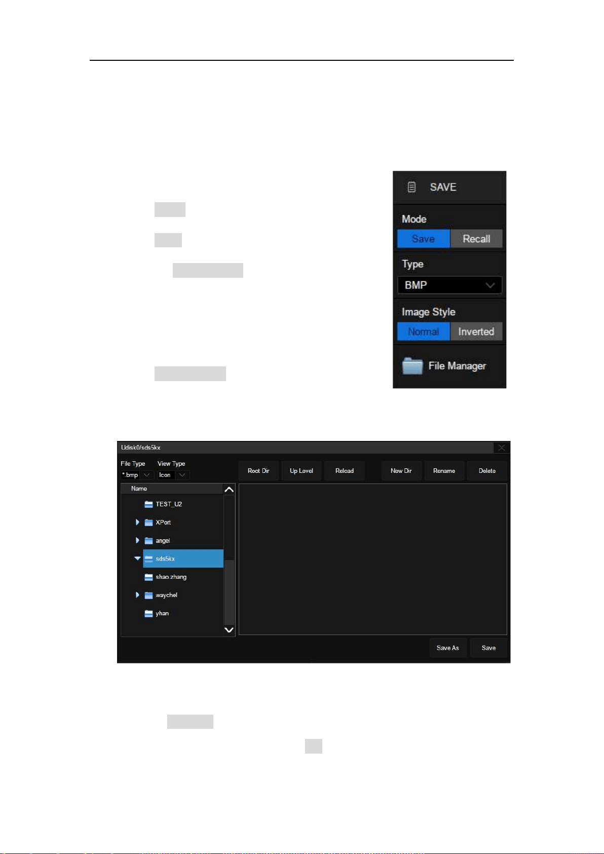
SDS5000X Series Digital Oscilloscope User Manual
210 / 236 W W W. S I G L E N T. C O M
Save the screen shot to the path “Udisk0\sds5kx\” in the format of BMP
First, Insert the U disk.
Secondly, set the parameters of the Save operation:
Select Mode as "Save"
Select Type as "BMP"
Select the Image Style. "Normal" saves images
with the same color of the display; "Inverted" saves
images with white background color for ink-saving
print
Touch File Manager to open the file manager
Third, select the \Udisk0\sds5kx\ directory in the file manager:
Fourth, touch Save As, click the pop-up text box to recall the virtual keyboard
and input the file name, and then touch OK:
SDS5000X Series Digital Oscilloscope User Manual
2 11 / 2 3 6 W W W. S I G L E N T. C O M
Once saved, the new BMP file is visible in the file manager:
In step 4, if Save is selected instead of Save As, the system saves the file as
the default file name sds5000x_n.bmp, where n is an integer incrementing from
1. For BMP images, the default save path is \BMP\. JPG images and PNG
images are similar.
Note: Pressing the Print button on the front panel quickly saves a screen shot
to the U disk.
SDS5000X Series Digital Oscilloscope User Manual
212 / 236 W W W. S I G L E N T. C O M
Recall the setup file "uart_decode.xml" stored in path “Udisk0\sds5kx\”
First, insert the U disk with the file "uart_decode.xml" stored folder “\sds5kx\”.
Second, set the parameters of the Recall operation:
Select Mode as "Recall"
Select Type as "Setup"
Select Recall Path as "External"
Touch File Manager to open the file manager
Third, select the \Udisk0\sds5kx\directory in the file manager, and then select
the setup file "uart_decode.xml"
Fourth, touch Recall and wait for the oscilloscope to finish recalling the setup.
SDS5000X Series Digital Oscilloscope User Manual
213 / 236 W W W. S I G L E N T. C O M
27 System Setting
Most of the system setting can be found in the Utility dialog box, such as
system status, language, sound, self-calibration, firmware upgrading.
27.1 System Status
Operate Utility>System Setting>System Status to check the system status.
System information includes the contents shown below.
27.2 Sound
Perform Utility>System Setting>Sound to enable or disable the audible buzzer.
:Indicates the buzzer is on.
SDS5000X Series Digital Oscilloscope User Manual
214 / 236 W W W. S I G L E N T. C O M
:Indicates the buzzer is off.
27.3 Upgrade Software
The firmware is upgradeable through external USB memory devices/U disk.
Make sure the U disk contains the correct upgrade file (*.ads) is connected to
the oscilloscope before performing the upgrade.
Operate Utility>System Setting>Upgrade to recall the upgrade dialog box:
Click Browse to open the file manager, select the correct upgrade file and click
OK:
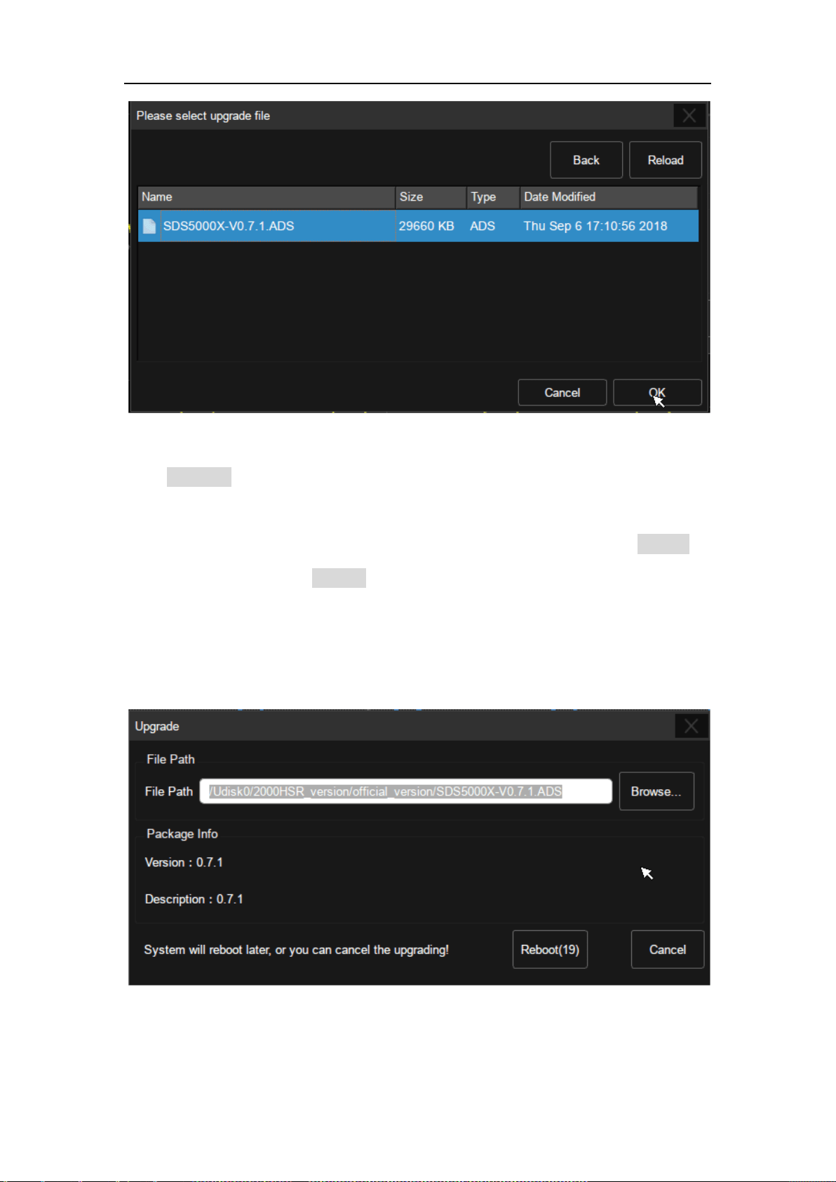
SDS5000X Series Digital Oscilloscope User Manual
215 / 236 W W W. S I G L E N T. C O M
Click Upgrade in the upgrade dialog box to start the upgrade. The oscilloscope
first copies the upgrade file (*.ads) to the local memory and parses it. If the
parse succeeds, it will show the following dialog. Users can choose Cancel to
cancel the upgrade, or Reboot to restart the oscilloscope immediately and
continue the upgrade. Otherwise the oscilloscope will restart automatically to
finish the upgrade.
After the reboot, check if version number in "System Status".
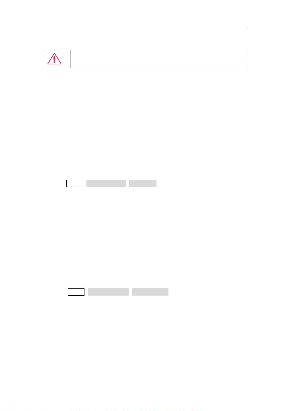
SDS5000X Series Digital Oscilloscope User Manual
216 / 236 W W W. S I G L E N T. C O M
Warning: Do Not turn off the power during upgrading. Otherwise, the
oscilloscope may not boot up any more!
27.4 Language
The SDS5000X supports multiple languages, including: Simplified Chinese,
Traditional Chinese, English, French, Japanese, German, Spanish, Russian,
Italian, Portuguese, and so on.
Operate Utility>System Setting> Language, and select the language in the list.
27.5 Screen Saver
Screen saver will be activated if the oscilloscope has not be operated for a
period. At this time the backlight of the display is cut off to save power
consumption.
Operate Utility>System Setting>Screen Saver to specify the period before
screen saver, or select "Off" to disable the screen saver.
Any action from the mouse, touch screen or front panel can disable the screen
saver.
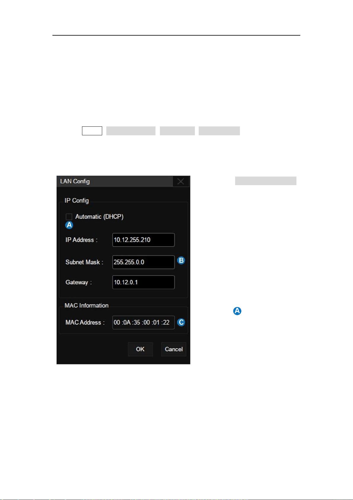
SDS5000X Series Digital Oscilloscope User Manual
217 / 236 W W W. S I G L E N T. C O M
27.6 I/O Setting
27.6.1 LAN
Operate the following steps to set the LAN port:
Perform Utility>System Setting>I/O Setting> LAN Config to open the LAN
Config dialog box.
A. Check Automatic (DHCP)
to enable dynamic IP. In
this case the oscilloscope
must be connected to the
local area network with a
DHCP server. Contact your
network administrator to
confirm the relevant
information.
B. When is not checked,
the oscilloscope uses static
IP. Set the static IP
address, subnet mask, and
gateway separately.
C. MAC address of the
oscilloscope, read only.
SDS5000X Series Digital Oscilloscope User Manual
218 / 236 W W W. S I G L E N T. C O M
27.6.2 Clock Source
The SDS5000X supports internal and external clock sources. When an external
clock source is used, the 10 MHz reference clock output of another instrument
can be used to achieve clock synchronization between two instruments.
Operate the following steps to set the clock source:
Utility>System Setting>I/O Setting> Clock Source.
A. Select the clock source as "Inner" or "Ext"
B. Turn on or off the 10 MHz output. The
option is only valid when the clock source
is "Inner". Turn on the 10 MHz output and
the SDS5000X can be used as a clock
source of other instruments.
C. Return to previous menu.
27.7 Date/Time
The SDS5000X has a RTC clock, which helps to record absolute time
information for screen shots, history frames and so on.
Operate Utility>System Setting> Date/Time to open the Date/Time dialog box:
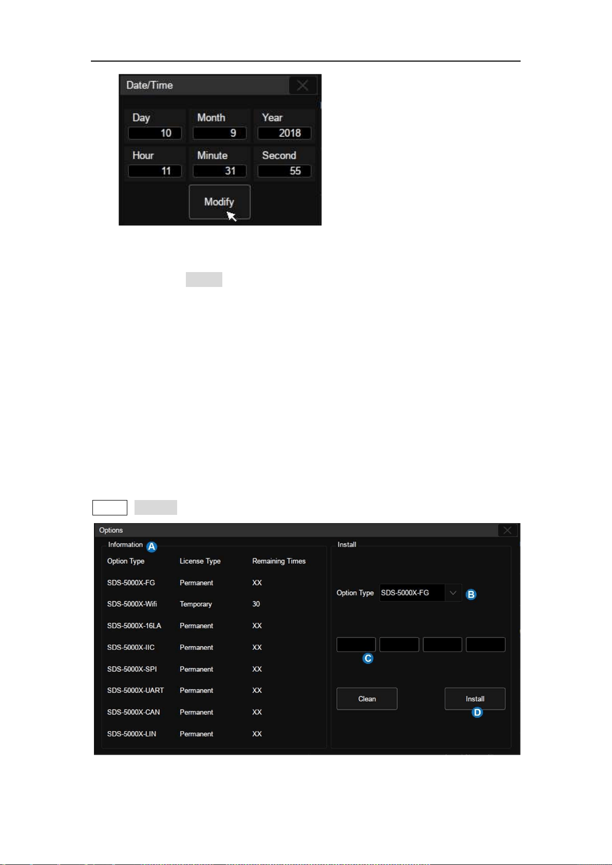
SDS5000X Series Digital Oscilloscope User Manual
219 / 236 W W W. S I G L E N T. C O M
Touch the text box of Hour, Minute, Second, Day, Month and Year to edit these
fields. Touch the Modify button to perform the change.
27.8 Install Options
The SDS5000X provides a few options to enhance its functionality. Contact
your local SIGLENT sales representative or SIGLENT technical support to get
the corresponding option key. Perform the following steps to install the option:
Utility>Options

SDS5000X Series Digital Oscilloscope User Manual
220 / 236 W W W. S I G L E N T. C O M
A. Option information display area. When the option is not activated, the
license type is displayed as "Temporary" and can be tried up to 30
times.
B. Select the option to install.
C. The option key input area, touch or click the text box and enter the key
by the virtual keyboard.
D. After entering the option key, click Install to perform the installation.

SDS5000X Series Digital Oscilloscope User Manual
221 / 236 W W W. S I G L E N T. C O M
27.9 Reference Position Setting
The reference position is used to set the strategy of scaling on the horizontal
and vertical axes, adapting different requirements.
Operate Utility>Reference Pos to open the dialog box, and choose the strategy
for the offset value change in the vertical (or horizontal) direction when the
vertical (or horizontal) scale is changed.
Horizontal Ref
Fixed Delay: When the timebase is changed, the horizontal delay
value remains fixed. As the horizontal timebase scale is changed, the
waveform expands/contracts around the center of the display
Fixed Position: When the timebase is changed, the horizontal delay
remains fixed to the grid position on the display. As the horizontal
timebase scale is changed, the waveform expands/contracts around
the position of the horizontal display.
Vertical Ref
Fixed Offset: When the vertical scale is changed, the vertical offset
remains fixed. As the vertical scale is changed, the waveform
expands/contracts around the main X axis of the display
Fixed Position: When the vertical scale is changed, the vertical offset
remains fixed to the grid position on the display. As the vertical scale
is changed, the waveform expands/contracts around the position of the
vertical ground position on display.
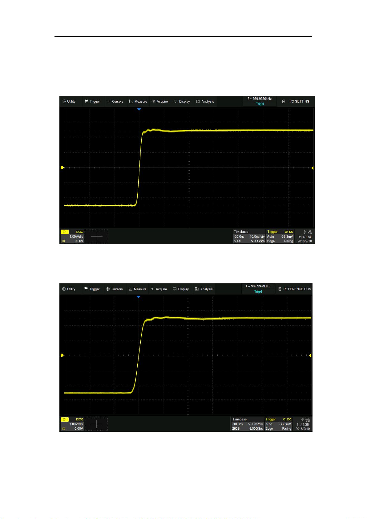
SDS5000X Series Digital Oscilloscope User Manual
222 / 236 W W W. S I G L E N T. C O M
Take Horizontal Ref as an example to demonstrate the scaling effect of different
settings:
Timebase=10 ns/div,Horizontal Delay=-20 ns=-2 div
Fixed position, timebase is changed to 5 ns/div, the grid number of delay (-2 div) remains
fixed, while the horizontal delay changes to -10 ns
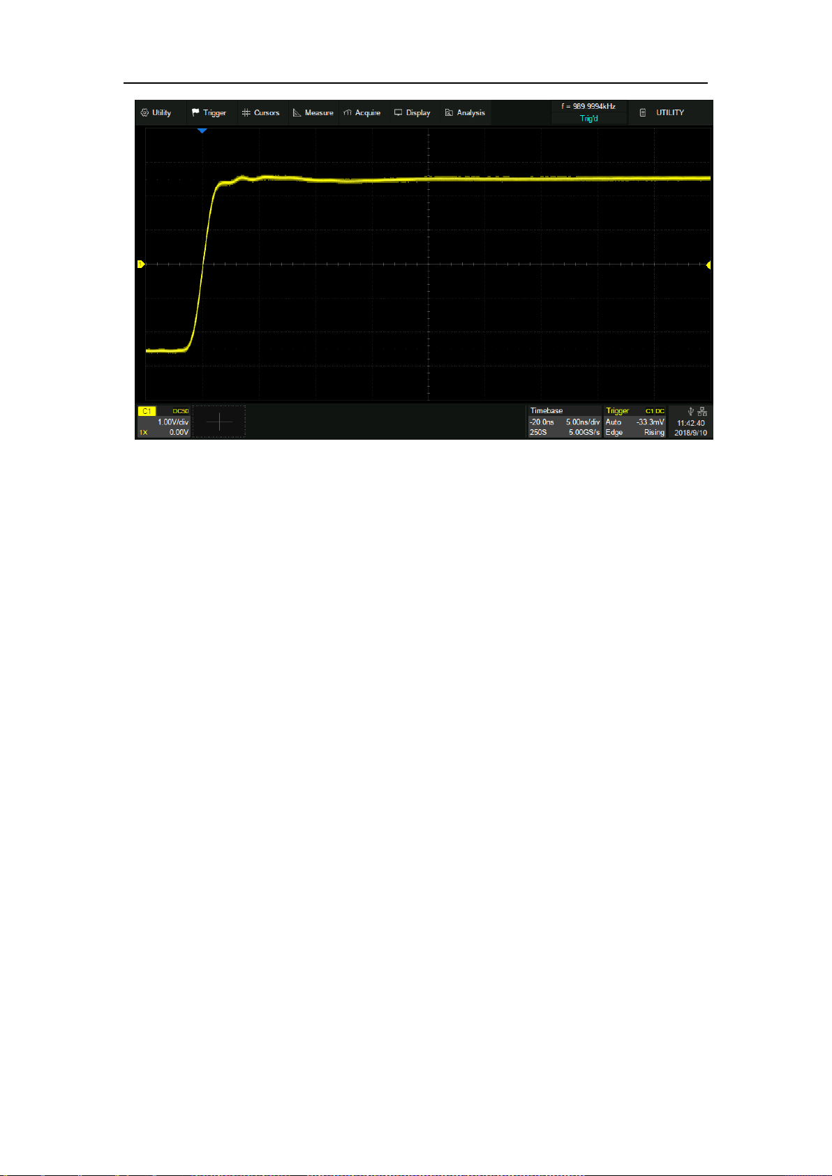
SDS5000X Series Digital Oscilloscope User Manual
223 / 236 W W W. S I G L E N T. C O M
Fixed delay, timebase is changed to 5 ns/div, the horizontal delay value remains fixed,
while the grid number of delay changes to -4 div

SDS5000X Series Digital Oscilloscope User Manual
224 / 236 W W W. S I G L E N T. C O M
27.10 Perform Self Test
The Self tests includes screen test, keyboard test and LED test. It is used to
check whether the oscilloscope has any electrical or mechanical problems on
the user interface such as color distortion, sensitivity of buttons and knobs.
Screen Test
The screen test is used to find out whether the oscilloscope display has serious
color distortion, bad pixels or screen scratches. Perform Utility>Do Self
Test>Screen Test, and the oscilloscope will enter the screen test interface as
shown below. The screen displays in blue at first.
Press the "Single" button to switch to red and green display mode. Observe
whether there is any color distortion, bad pixel or scratch on the screen.
Press the "Run/Stop" button to exit the screen test mode.
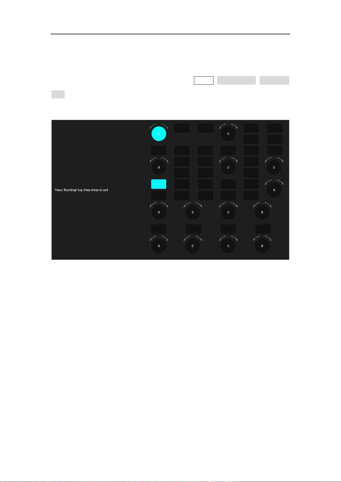
SDS5000X Series Digital Oscilloscope User Manual
225 / 236 W W W. S I G L E N T. C O M
Keyboard Test
The keyboard test is used to check whether the oscilloscope front panel buttons
or knobs are responsive or sensitive. Perform Utility>Do Self Test>Keyboard
Test to recall the following interface:
Knob test: Turn each knob clockwise, counter-clockwise, and press down.
Observe whether the value on the corresponding knob (default 0) on the screen
increases or decreases in real time and whether the knob lights up when it is
pressed.
Button test: Press each button and check whether the corresponding button
icon on the screen lights up in real time.
Press the "Run/Stop" button three times to exit the keyboard test.
SDS5000X Series Digital Oscilloscope User Manual
226 / 236 W W W. S I G L E N T. C O M
LED Test
The LED test is used to check whether the button backlight on the front panel
is functional. Operate Utility>Do Self Test >LED Test to recall the following
interface:
Press the "Single" button and the first LED on the front panel will light. The
corresponding position of the key on the screen will also change color. Press
the "Single" button to check the next button. Press the "Single" button
consecutively until all the backlights are tested.
Press the "Run/Stop" button to exit the LED test.
SDS5000X Series Digital Oscilloscope User Manual
227 / 236 W W W. S I G L E N T. C O M
27.11 Do Self Cal
The self-calibration program can quickly calibrate the oscilloscope to reach the
best working state and the most precise measurement. It is recommended to
perform a self-calibration if the change of ambient temperature is more than
5 ℃.
Note: Make sure the oscilloscope has been warmed up or operated for more
than 30 minutes before the self-calibration.
Please do the self-calibration as follows:
1. Disconnect everything from all inputs.
2. Operate Utility>Do Self Cal, and it will pop up the following dialog.
Select Continue to start the self-cal program.
3. The oscilloscope will not response to any operate until the self-cal is
finished. After the self-cal is completed, touch the screen or press any
button to exit.

28 Remote Control
The SDS5000X provides a LAN port and a USB Device port which can be used
for remote control in multiple ways.
28.1 Web Brower
A built-in web server provides an approach to visit the oscilloscope by web
browser. It doesn’t require any additional software to be installed in the
computer. Set the LAN port correctly (see section “LAN” for details), input the
IP address of the oscilloscope in the browser address bar, and then the user
can browse and control the oscilloscope in the web.
SDS5000X Series Digital Oscilloscope User Manual
230 / 236 W W W. S I G L E N T. C O M
A. Input the IP address of the instrument
B. Information of the instrument
C. Click here to recall the instrument control interface
Below is the instrument control interface:
A. Display and control area of the instrument. The display in this area is
a copy from the instrument display. Using the mouse to operate in the
area is equivalent to directly operating the touch screen display of the
instrument.
B. Click here to perform a screen shot
C. Click here to perform a firmware upgrade

SDS5000X Series Digital Oscilloscope User Manual
231 / 236 W W W. S I G L E N T. C O M
28.2 Other Connectivity
The SDS5000X also supports remote control of the instrument by sending SCPI
commands via NI-VISA, Telnet, or Socket. For more information, refer to the
programming guide of this product.

SDS5000X Series Digital Oscilloscope User Manual
232 / 236 W W W. S I G L E N T. C O M
29 Troubleshooting
The commonly encountered failures and their solutions are listed below. When
you encounter those problems, please solve them following the corresponding
steps. If the problem remains still, please contact SIGLENT as soon as possible.
1. The screen is still dark (no display) after power on:
1) Check whether the power is correctly connected.
2) Check whether the power switch is really on.
3) Check whether the fuse is burned out. If the fuse needs to be
changed, please contact SIGLENT timely and return the instrument
to the factory for replacement by the maintenance personnel
authorized by SIGLENT.
4) Restart the instrument after finishing the above inspections.
5) If it still does not work correctly, please contact SIGLENT.
2. The signal is sampled but no waveform of the signal is displayed:
1) Check whether the probe is correctly connected to the signal
connecting wire.
2) Check whether the signal connecting wire is correctly connected to
the BNC (namely channel connector).
3) Check whether the probe is correctly connected to the item to be
tested.
4) Check whether there are signals generated from the item to be
tested.
5) Resample the signal.

SDS5000X Series Digital Oscilloscope User Manual
233 / 236 W W W. S I G L E N T. C O M
3. The tested voltage amplitude is greater or lower than the actual value
(Note that this problem usually occurs when probe is used):
1) Check whether the attenuation coefficient of the channel complies
with the attenuation ratio of the physical probe.
2) Disconnect the oscilloscope from the external signal and do a self-cal.
4. There is waveform display but not stable:
1) Check the trigger signal source: check whether the source item at
the trigger panel complies with the signal channel actually used.
2) Check whether it is a "false wave”: when the signal frequency is
very large (more than half of the sample rate), it is easy to appear
a "false wave". At this point, a small time base should be set to
make the sample rate more than 2 times of the signal frequency.
3) Check the trigger type: general signals should use “Edge” trigger
and video signal should use “Video” trigger. Only when the proper
trigger type is used, can the waveform be displayed stably.
4) Change the trigger holdoff setting.
5. No display after pressing Run/Stop:
Check whether the mode at the trigger panel (TRIGGER) is on “Normal”
or “Single” and whether the trigger level exceeds the waveform range.
If yes, set the trigger level to the middle or set the mode to “Auto”.
Note: Using Auto could automatically finish the above setting.
6. Touch screen does not respond to touch operation:

SDS5000X Series Digital Oscilloscope User Manual
234 / 236 W W W. S I G L E N T. C O M
1) Check whether the Touch button backlight on the front panel is
lighted up. If not, the touch screen is not turned on. Press the button
to enable the touch screen
2) Restart the instrument.
7. The USB storage device cannot be recognized:
1) Check whether the USB storage device can work normally.
2) Make sure whether the USB interface can work normally.
3) Make sure that the USB storage device being used is flash storage
type. This oscilloscope does not support hardware storage type.
4) Make sure that the U disk system format is FAT32.
5) Restart the instrument and then insert the USB storage device to
check it.
6) If the USB storage device still cannot be used normally, please
contact SIGLENT.

SDS5000X Series Digital Oscilloscope User Manual
235 / 236 W W W. S I G L E N T. C O M
30 Contact SIGLENT
America
SIGLENT Technologies NA, Inc
6557 Cochran Rd Solon, Ohio 44139
Tel: 440-398-5800
Toll Free:877-515-5551
Fax: 440-399-1211
info@siglent.com
www.siglentamerica.com
Headquarters
SIGLENT TECHNOLOGIES CO., LTD.
Blog No.4 & No.5, Antongda Industrial Zone, 3rd Liuxian Road, Bao’an District, Shenzhen, 518101, China.
Tel:+ 86 755 3688 7876
Fax:+ 86 755 3359 1582
market@siglent.com
www.siglent.com/ens
Europe
SIGLENT TECHNOLOGIES EUROPE GmbH
Liebigstrasse 2-20, Gebaeude 14, 22113 Hamburg Germany
Tel: +49(0)40-819-95946
Fax: +49(0)40-819-95947
info-eu@siglent.com
www.siglenteu.com
SDS5000X Series Digital Oscilloscope User Manual
236 / 236 W W W. S I G L E N T. C O M