Circuit Specialists, Inc
Single Output Adjustable DC Bench Power Supplies with Large LED Displays
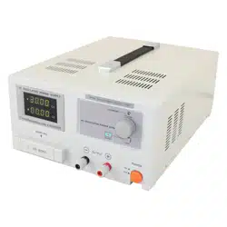
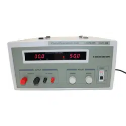
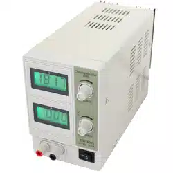
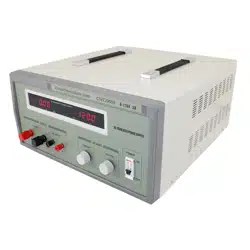
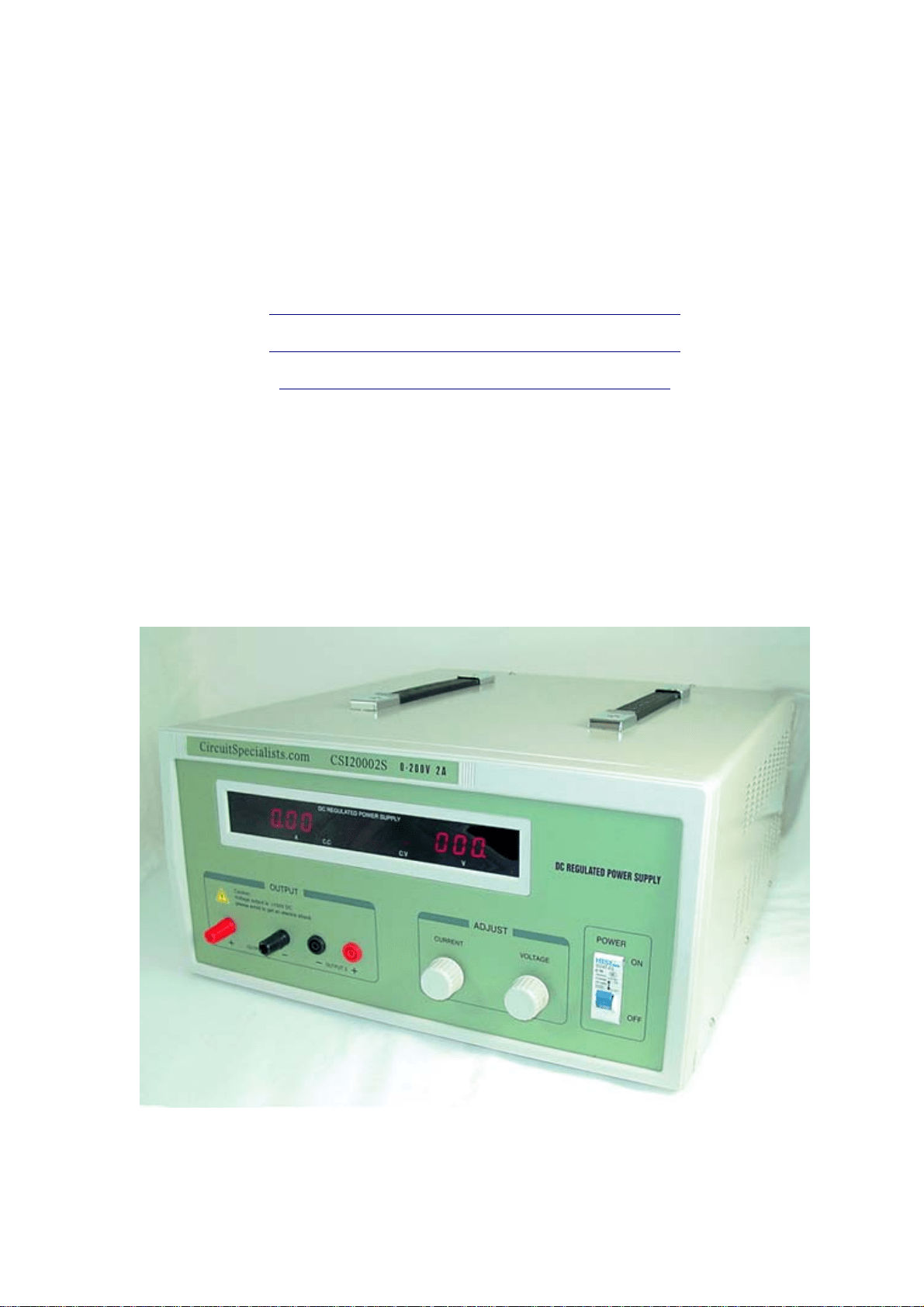
CSI12005S………..0-120VDC/ 0-5A Regulated Power Supply
CSI20002S………..0-200VDC/ 0-2A Regulated Power Supply
CSI5030S………0-50VDC/0-30A Regulated Power Supply
Circuit Specialists Inc
220 S. Country Club Dr., Bldg. #2
Mesa, AZ. 85210
Tel: 800-528-1417/ 480-464-2485
Fax:480-464-5824
Internet: www.CircuitSpecialists.com

INTRODUCTION:
CSI12005S, CSI20002S and CSI5030S series of Adjustable DC
Voltage and Current Regulated Power Supplies are high precision
DC Power Supplies with continuously adjustable voltage and
current outputs. They feature automatic switching between voltage
regulation and current regulation. The output voltage (CV) is
adjustable starting from zero volts and can be set arbitrarily
through the rated range. When it is in the (CC) mode, the current
regulation is continuously adjustable through the rated range.
These CSI series Power Supplies have large LED output voltage
and current displays.
Model CSI12005S CSI20002S CSI5030S
Rated Voltage 0—120V 0—200V 0—50V
Rated Current 0—5A 0—2A 0—30A
1. General Specifications
1.1 Input Voltage 110V ±10% 50Hz—60Hz
1.2 Output Voltage: see the form above
1.3 Output Current: see the form above
1.4 Source Regulation:1×10
-3
+5mV
1.5 Load Regulation: 1×10
-3
+5mV
1.6 Ripple&Noise:≤10mVrms
1.7 Protection: Current-limiter Protection
1.8 Voltage Display Accuracy: 1% +3d
1.9 Current Display Accuracy: 2% +3d
1.10 Working Environment:0—+40℃ Relative Humidity:
<90%
1.11 All units are heat sink and fan cooled.
NOTE: CSI5030 can not work for long hours at full load due to
excessive heat build up. Below are estimated run times. Actual
performance is affected by environmental factors including
ventilation in area of use.
50V – 30A = 1 Hour at 1500Watts (FULL CAPACITY,
Uninterupted)
50V – 25A = 2 Hours at 1250Watts Uninterupted
50V – 20A = 6 Hours at 1000Watts Uninterupted
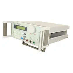
2: OPERATION
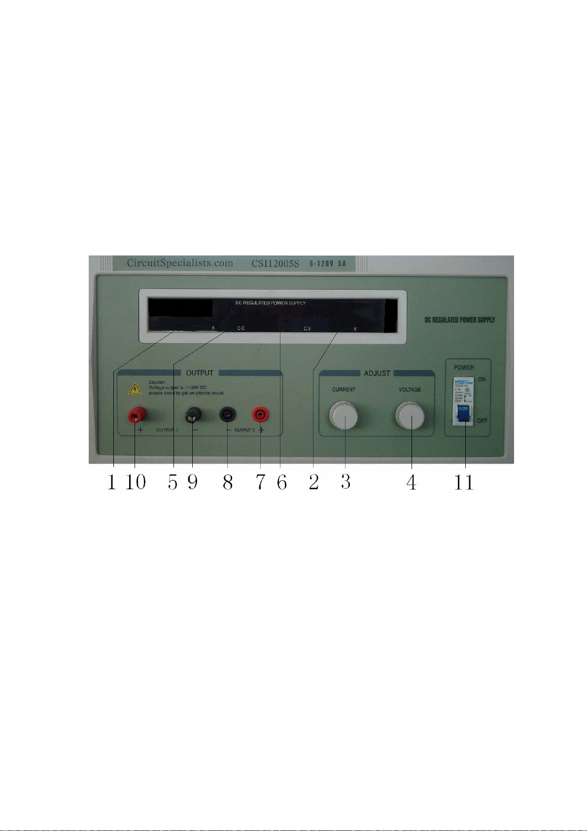
2.1 The locations and functions of the knobs and switches on the panel
(1) Current Display: to display the output current.
(2) Voltage Display: to display the output voltage.
(3) Current Regulation Adjustment Knob and to set the current-limit
protection point.
(4) Voltage Regulation Adjustment Knob: to adjust the output voltage
value.
(5) CC : Constant Current state LED.
(6) CV: Constant Voltage state LED.
(7) The positive output terminal. To be connected with the positive end
of the load----Normally for test, examine and repair, or to be

connected with an external high precision measuring instrument.
(8) The negative terminal of output, to be connected with the negative
end of the load----Normally for test, examine and repair, or to be
connected with an external high precision measuring instrument.
(9) The positive terminal of output, to be connected with the positive end
of the load.
(10) The negative terminal of output, to be connected with the negative
end of the load.
(11) Power Switch. Flip up to turn the power “ON”; flip down to turn the
power “OFF”.
2.2 Load Connection
Connect the positive end of the load to the positive terminal (#7) or
(#10) and the negative end of the load to the negative terminal
(#9). When the power is turned on, the LED displays the output
current value and displays the output voltage value. If the current is
past the rated range and the CC (#5) indicator is lit, then there is an
overload or short-circuit. Please adjust the load to have the unit
recover from this state.
2.3 To use as a Constant Current Power Source (CC)
After turning on the power, turn the Voltage Regulation
Adjustment Knob (#4) clockwise to maximum, and turn the
Current Regulation Adjustment Knob (#3) counterclockwise to
minimum, then connect the load and turn the Current Regulation
Adjustment Knob (#3) clockwise until the output current gets to
the desired current setting.
2.4 To use the unit as a Voltage Power Source (CV)
Turn the Current Regulation Adjustment Knob (#3) clockwise to
the maximum. The current-limit protection point can be set
arbitrarily at the same time and the method is as follows: turn on
the power supply, connect the unit with an appropriate load of
variable resistance and adjust the resistance to make the output
current equal to the value at the current-limit protection point, then

turn the Current Regulation Adjustment Knob (#3)
counterclockwise to make the (CC) indicator come on, the current-
limit protection point is set at this point and can be decreased or
increased with Knob (#3).
3. Precautions:
3.1 After every use, put the unit in a place where it is dry,
ventilation is good and where it will stay clean. If this unit is
not in use for a long periods of time, please remove the plug
before storing it.
3.2 These units should only be repaired by qualified repair
technicians, as some components retain an electrical charge and
can cause serious harm or even cause a fatality if handled
incorrectly.
3.3 When this power supply is used with Wireless Power
Emission Equipment, the displayed voltage and current may
not be stable. (The displays may become disrupted by the high
output radio frequencies) Please use a low-resistance analog
meter to choose more accurate settings under these
circumstances.
Warranty Statement:
Circuit Specialists, Inc. warrants this product to be free from defects caused by
workmanship or production error for a period of 12 months after the initial purchase date.
Circuit Specialists Inc. will, at its’ option, repair or replace any defective unit with a
working unit after the defective product has been returned, freight prepaid to Circuit
Specialists, Inc. Should you have a defect that is covered by this limited warranty, please
contact Circuit Specialists, Inc. (1-800-528-1417/ 480-464-2485) for an RMA number
prior to returning the unit. Products that are damaged from misuse are not covered by this
limited warranty.