
Model:PAC366FC
PAC606FC
USER'S MANUAL
PAC486FC
PAC3663FC
PAC4863FC
PAC4873C
PAC6063FC
LIGHT COMMERCIAL AIR CONDITIONER

CONTENT
IMPORTANT SAFETY INFORMATION---------------------------------------------------------------------1
PARTS NAMES---------------------------------------------------------------------------------------------------2
ADJUSTING AIR FLOW DIRECTION-----------------------------------------------------------------------13
HINTS FOR ECONOMICAL OPERATION-----------------------------------------------------------------2
TEMPORARY OPERATIONS---------------------------------------------------------------------------------14
MAINTENANCE-------------------------------------------------------------------------------------------------14
AIR CONDITIONER OPERATIONS AND PERFORMANCE------------------------------------------16
INSTALLATION----------------------------------------------------------------------------------------------------17
TROUBLES AND CAUSES----------------------------------------------------------------------------------18
TROUBLES AND CAUSES(CONCERNING REMOTE CONTROLLER)-------------------------18
Danger
No
Household
Drain
Cleaner
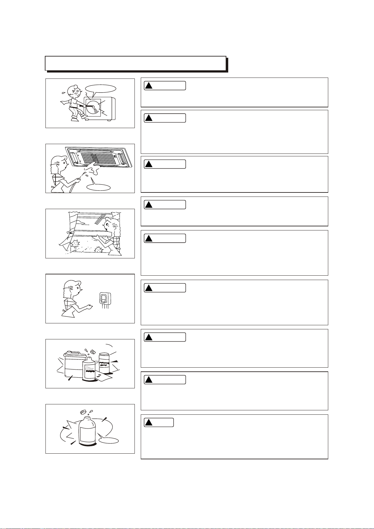
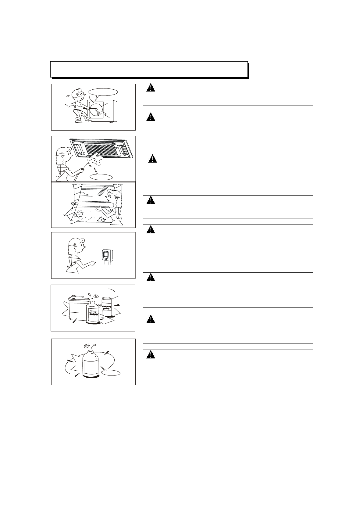
IMPORTANT SAFETY INFORMATION
Do not attempt to install this unit by yourself. This unit requires
installation by qualified persons.
Do not use caustic household drain cleaners in the unit. Drain
cleaners can quickly destroy the unit components (drain pan and
heat exchanger coil etc).
CAUTION
CAUTION
NOTE
DANGER
DANGER
WARNING
WARNING
WARNING
Do not attempt to service the unit yourself. This unit has no user
serviceable components. Opening or removing the cover will
expose you to dangerous voltage. Tuning off the power supply will
not prevent potential electric shock.
To avoid the risk of serious electrical shock, Never sprinkle or
spill water or liquids on unit.
Ventilate the room regularly while the air conditioner is in use,
especially if there is also a gas appliance in use in this room,
Failure to follow these directions may result in a loss of oxygen
in the room.
To prevent electric shock, turn off the power or disconnect the
power supply plug before beginning any cleaning or other routine
maintenance. Follow the directions for cleaning in the Owner's
Manual.
1
!!
!!
!!
!!
!!
!!
!!
!!
!!
No
Thinner
DANGER
Never put hands or objects into the Air Outlet of indoor or outdoor
units. These units are installed with a fan running at high speed.
To touch the moving fan will cause serious injury.
Do not use liquid cleaners or aerosol cleaners, use a soft and dry
cloth for cleaning the unit. To avoid electric shock, never attempt
to clean the units by sprinkling water.
For proper performance, operate the unit in temperature and
humidity ranges indicated in this owner's manual. If the unit is
operated beyond these conditions, it may cause malfunctions
of the unit or dew dripping from the unit.
HINTS FOR ECONOMICAL OPERATION
The following should be noticed to ensure an economical operation. (Refer to corresponding chapter
for details)
Adjust the air flow direction properly to avoid winding toward your body.
Adjust the room temperature properly to get a comfortable situation and to avoid supercooling and
superheat.
In cooling, close the curtains to avoid direct sunlight.
To keep cool or warm air in the room, never open doors or windows more often than necessary.
Set the timer for the desired operating time.
Never put obstructions near the air outlet or the air inlet. Or it will cause lower efficiency, even a
sudden stop.
If you don't plan to use the unit for a long time, please disconnect power and remove the batteries
from the remote controller. When the power switch is connected, some energy will be consumed,
even if the air conditioner isn't in operation. So please disconnect the power to save energy. And
please switch the power on 12 hours before you restart the unit to ensure a smooth operation.
A clogged air filter will reduce cooling or heating efficiency, please clean it once two weeks.
PARTS NAMES
f
b
d
e
i
m
n
l
p
o
c
CC
q
a
j
k
e
g
d
e
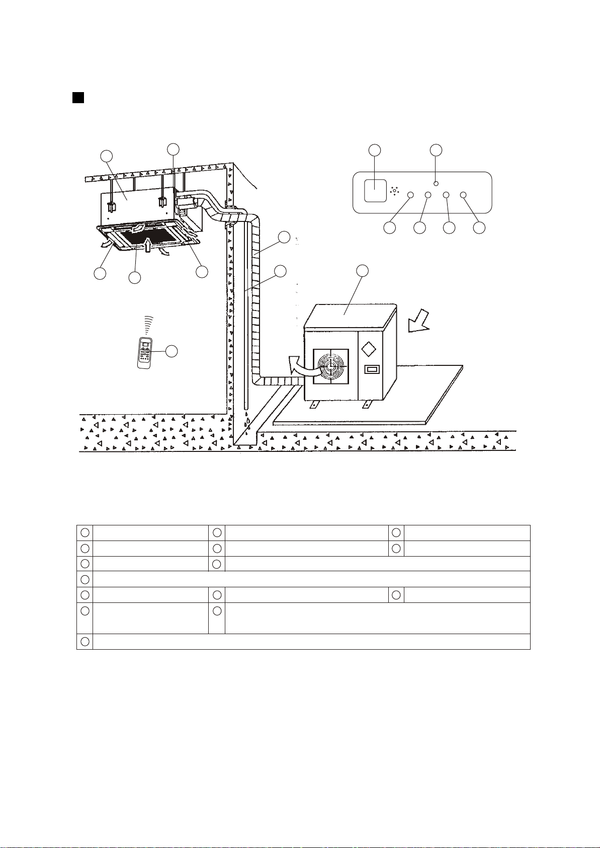
Display Panel
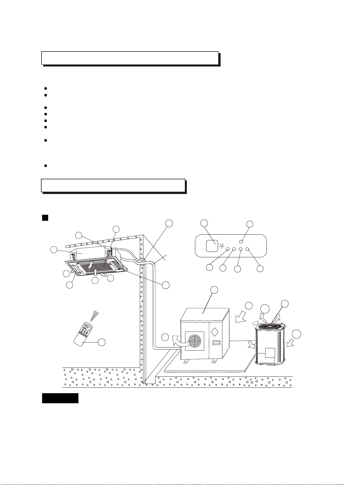
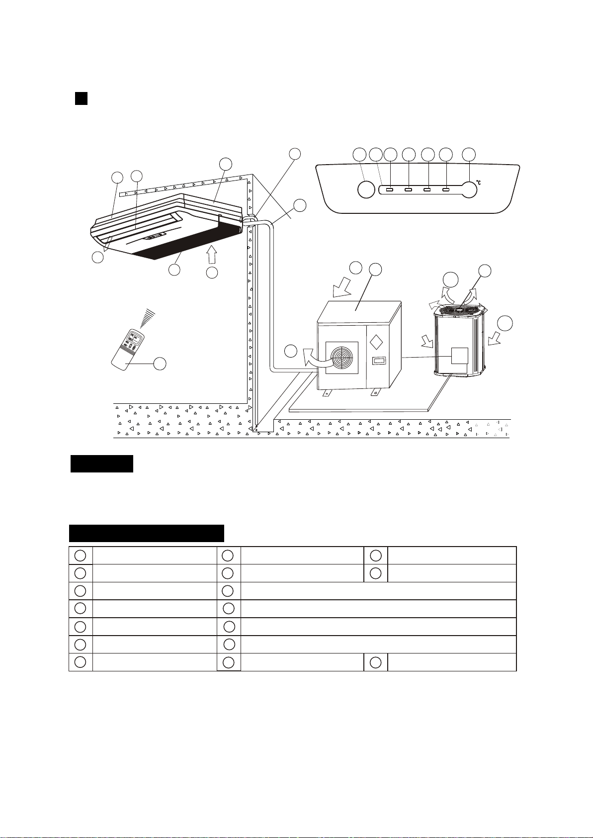
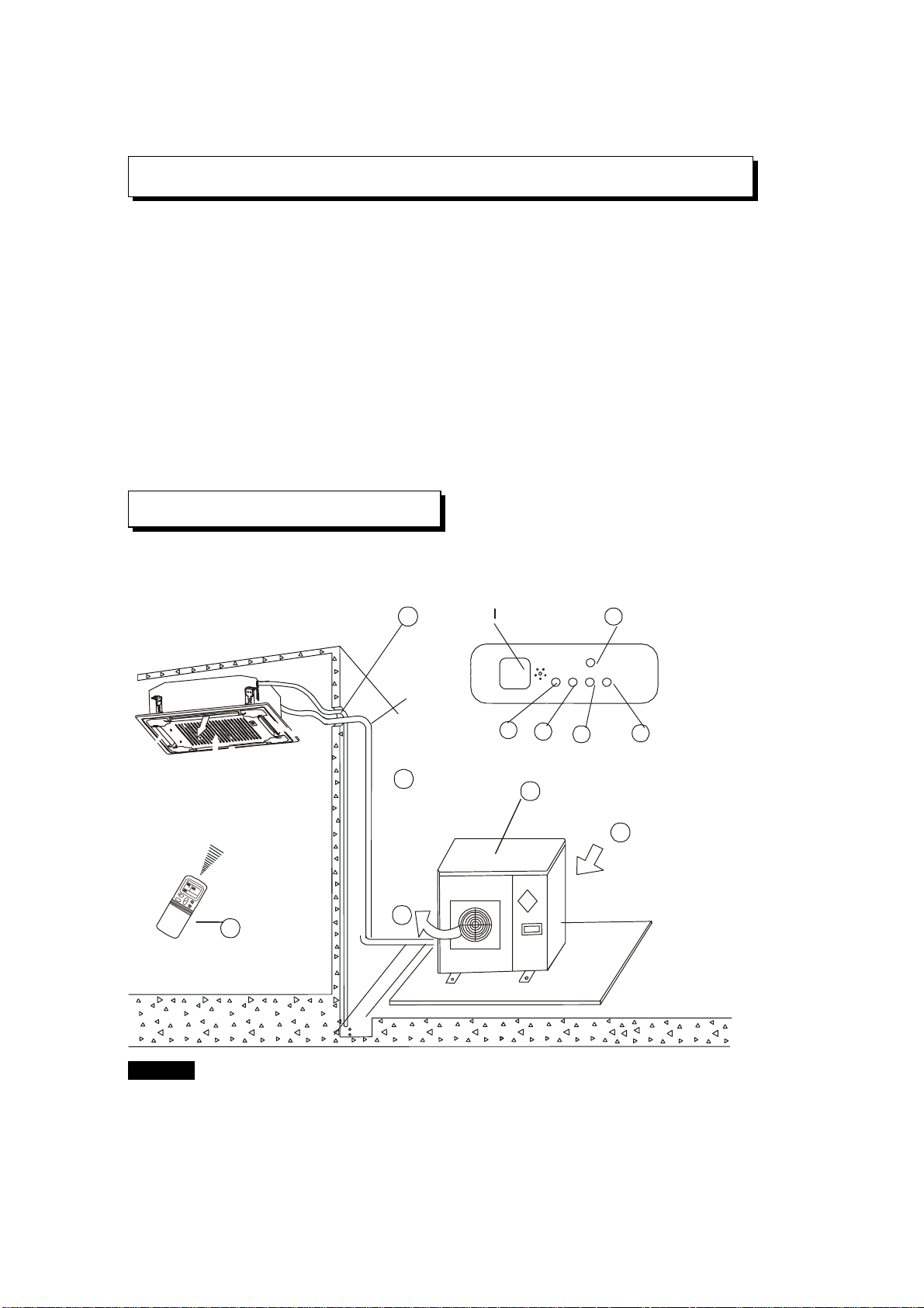
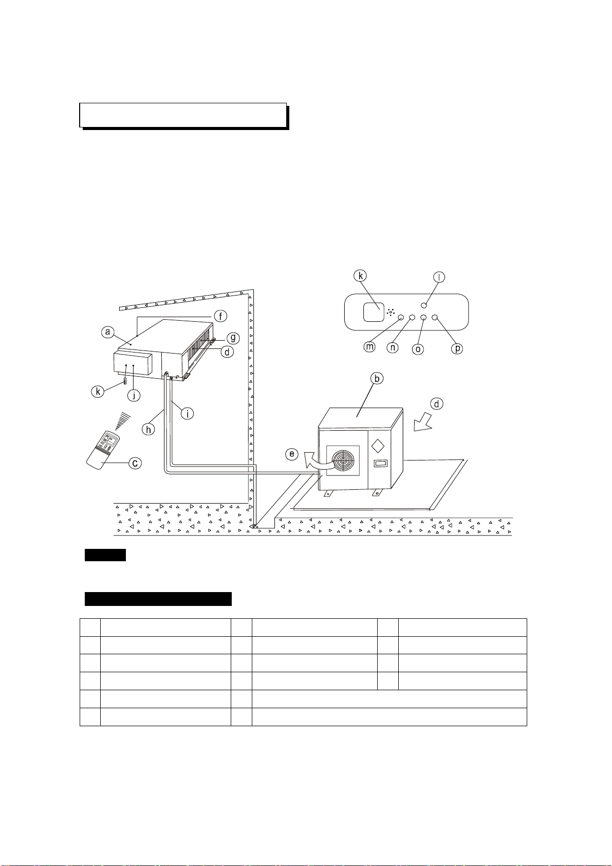
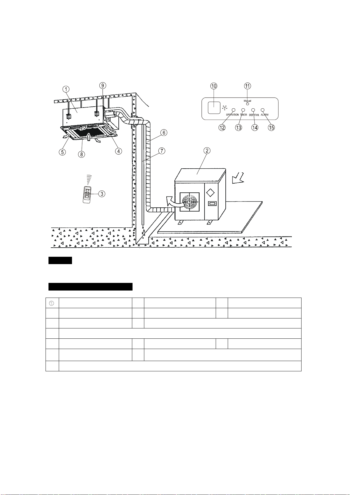
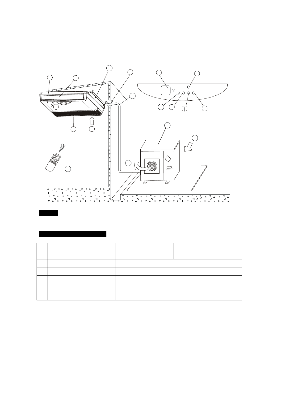
The air conditioner consists of the indoor unit, the outdoor unit, the connecting pipe and the remote
controller.
Cassette Type
NOTICE!
This chart is based on 24000Btu/h type. So, a few differences may exist on the outlook and functions
from yours.
2
b
d
e
or
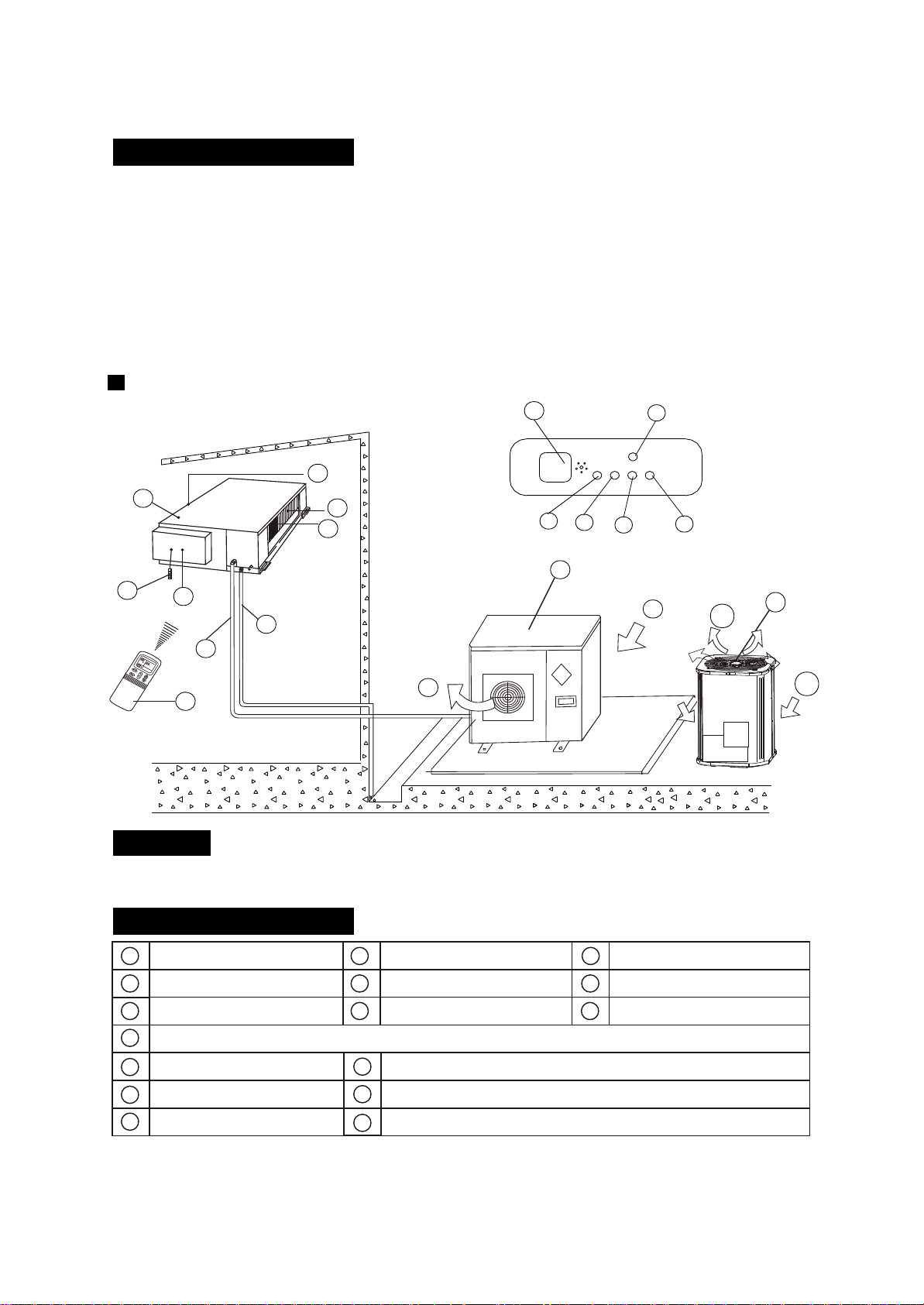
a) indoor unit b) outdoor unit
c) remote controller d) air-in
e) air-out f ) air outlet
g) air flow louver (at air outlet) h) connecting pipe
i ) drain hose j ) air inlet (with air filter in it)
k) drain pump (drain water from indoor unit) l ) infrared signal receiver
m) temporary button n) operation lamp
o) timer indicator
p) PRE-DEF indicator (cooling and heating type) or fan only indicator (cooling only type)
q) alarm indicator
NAMES AND FUNCTIONS
NAMES AND FUNCTIONS
h
b
d
e
i
m
n
l
p
o
b
c
f
a
d
e
g
h
i
j
k
m
o
p
l
n
c
C
k
f
d
j
a
k
g
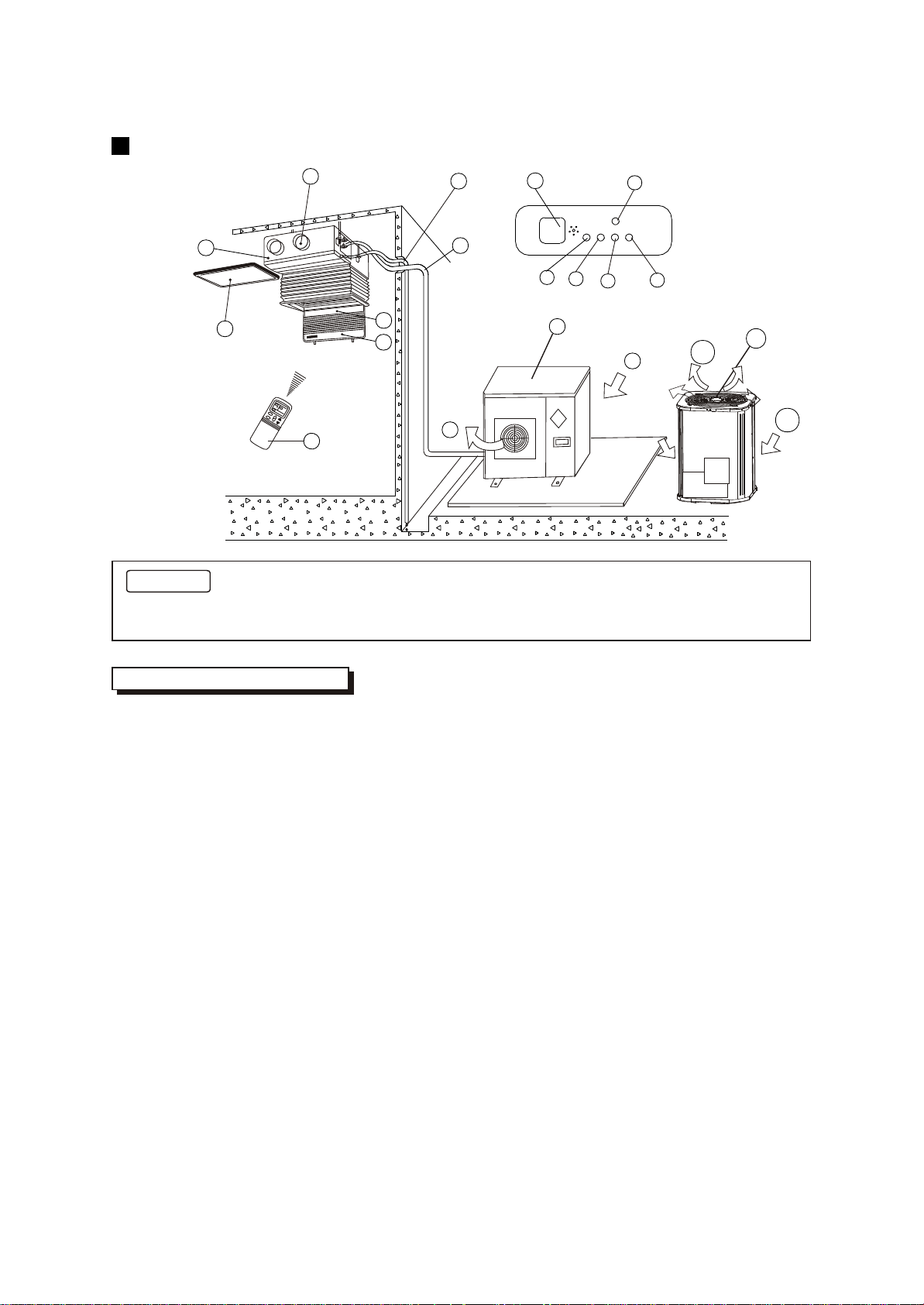
Display Panel
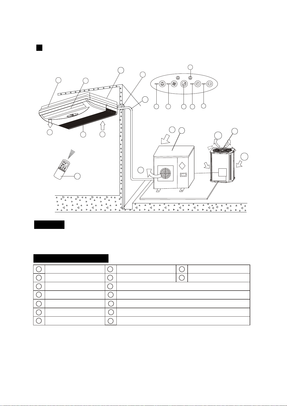
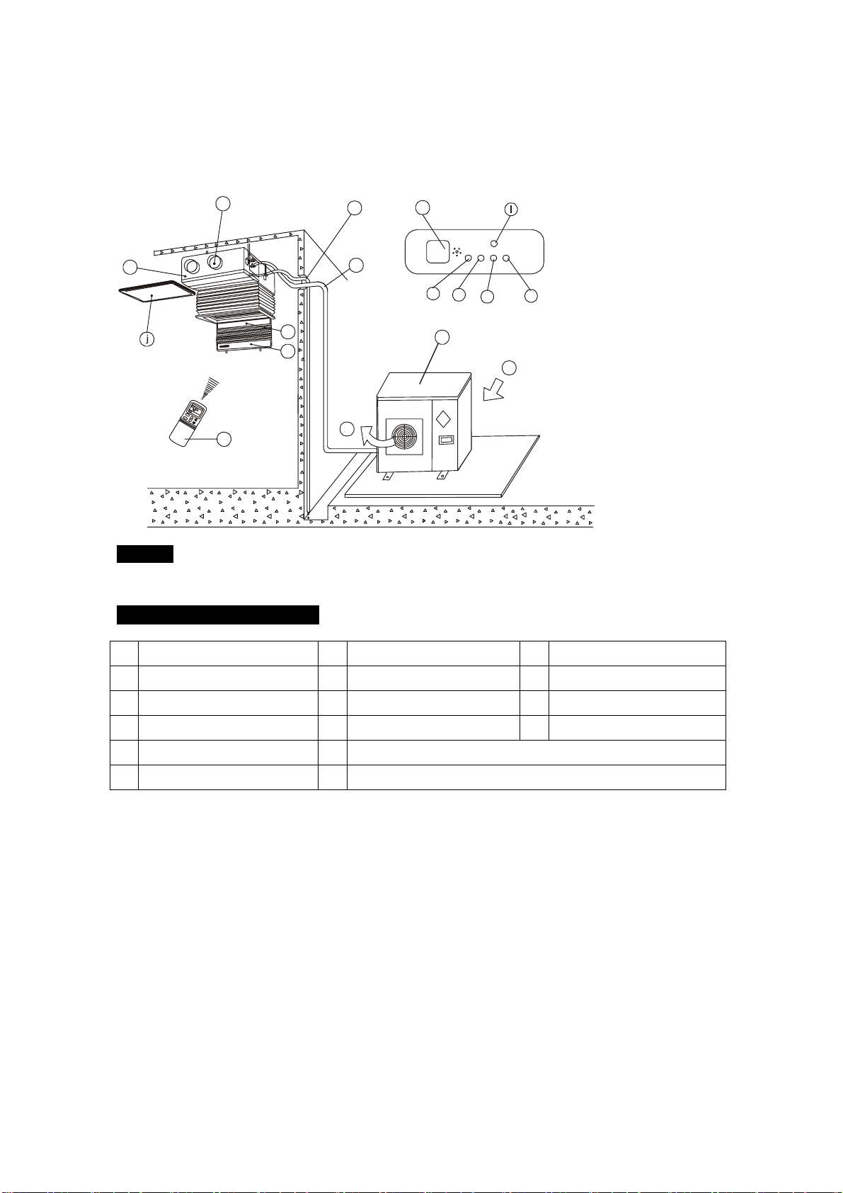
High-static Pressure Parvis Split Type
NOTICE!
This chart is based on 24000Btu/h type. So, a little differences may exist on the outlook and functions
from yours.
indoor unit
air-inlet
heat exchanger
outdoor unit
air-out
connecting pipe
E-Box
remote controller
air outlet
drain hose
infrared signal receiver
operation lamp
timer indicator
temporary button
PRE-DEF indicator
(cooling and heating type) or fan only indicator (cooling
alarm indicator
only type)
3
b
d
e
or
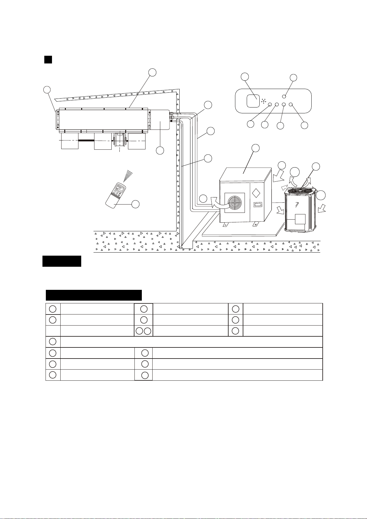
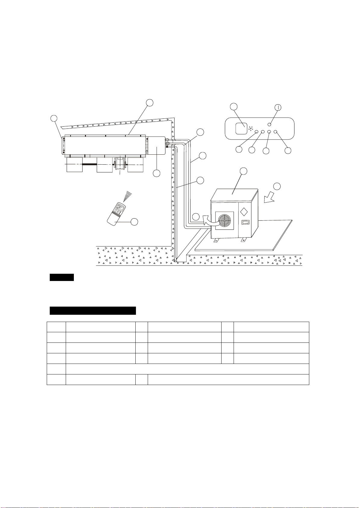
Duct and Ceiling Type
h
b
f
d
d
e
i
m
n
l
p
o
c
CC
j
a
g
k
NOTICE!
This chart is based on 24000Btu/h type. So, a few differences may exist on the outlook and
functions from yours.
a) indoor unit b) outdoor unit
c) remote controller d) air-in
e) air-out f ) air outlet
g) air flow louver (at air outlet) h) connecting pipe
i ) drain hose j ) air inlet (with air filter in it)
k) infrared signal receiver l ) manual button
m) operation lamp n) timer indicator
o) PRE-DEF indicator p) alarm indicator
(NOTICE: In the case of "cooling only type", it is the "FAN ONLY" indicator.)
NAMES AND FUNCTIONS
4
b
d
e
or
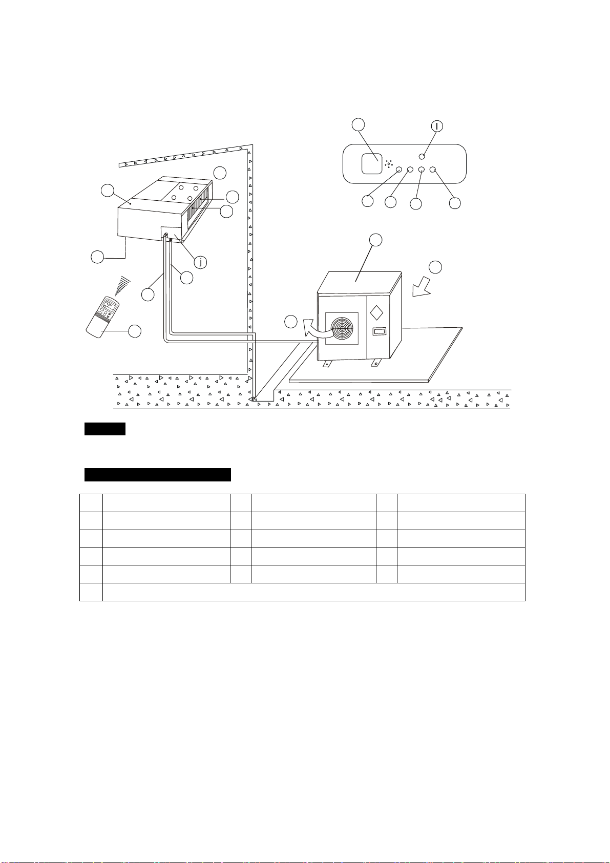
NOTICE!
This chart is based on 24000Btu/h. type. So, a few differences may exist on the outlook and functions from yours.
For Slim Duct Type
f
b
d
e
i
m
n
l
p
o
c
ÎÂ
¶ÈÎÂ
¶È
ʱ
ÖÓʱ
ÖÓ
·çËÙ
·çËÙ
Ä£
ʽģ
ʽ
·çËÙ ·çËÙ
¿ª¿ª
¹Ø¹Ø
ζÈζÈ
×Ô
¶¯×Ô
¶¯
C
C
a
Display Panel
h
g
k
j
NAMES AND FUNCTIONS
b
c
f
a
d
e
g
h
i
j
k
m
o
p
l
n
indoor unit
air-out
outdoor unit
air-inlet
connecting pipe
E-Box
remote controller
air- outlet
drain hose
infrared signal receiver
operation lamp
timer indicator
temporary button
PRE./DEF. indicator
(cooling and heating type) or fan only indicator (cooling
alarm indicator
only type)
5
b
d
e
or
NAMES AND FUNCTIONS
h
b
d
e
i
m
n
l
p
o
b
c
f
a
d
e
g
h
i
j
k
m
o
p
l
n
c
ζÈ
ʱÖÓ
·çËÙ
ģ ʽ
·ç
ËÙ
¿ª
¹Ø
ζÈ
×Ô
¶¯
C
k
f
d
j
a
f
g
Display Panel
indoor unit
air-out
heat exchanger
outdoor unit
air-outlet
connecting pipe
E-Box
remote Controller
air- inlet
drain hose
infrared signal receiver
operation lamp
timer indicator
temporary button
PRE./DEF. Indicator
(Cooling and heating type) or fan only indicator (cooling
alarm indicator
only type)
For Slim DUCT with air inlet box Type
6
b
d
e
or
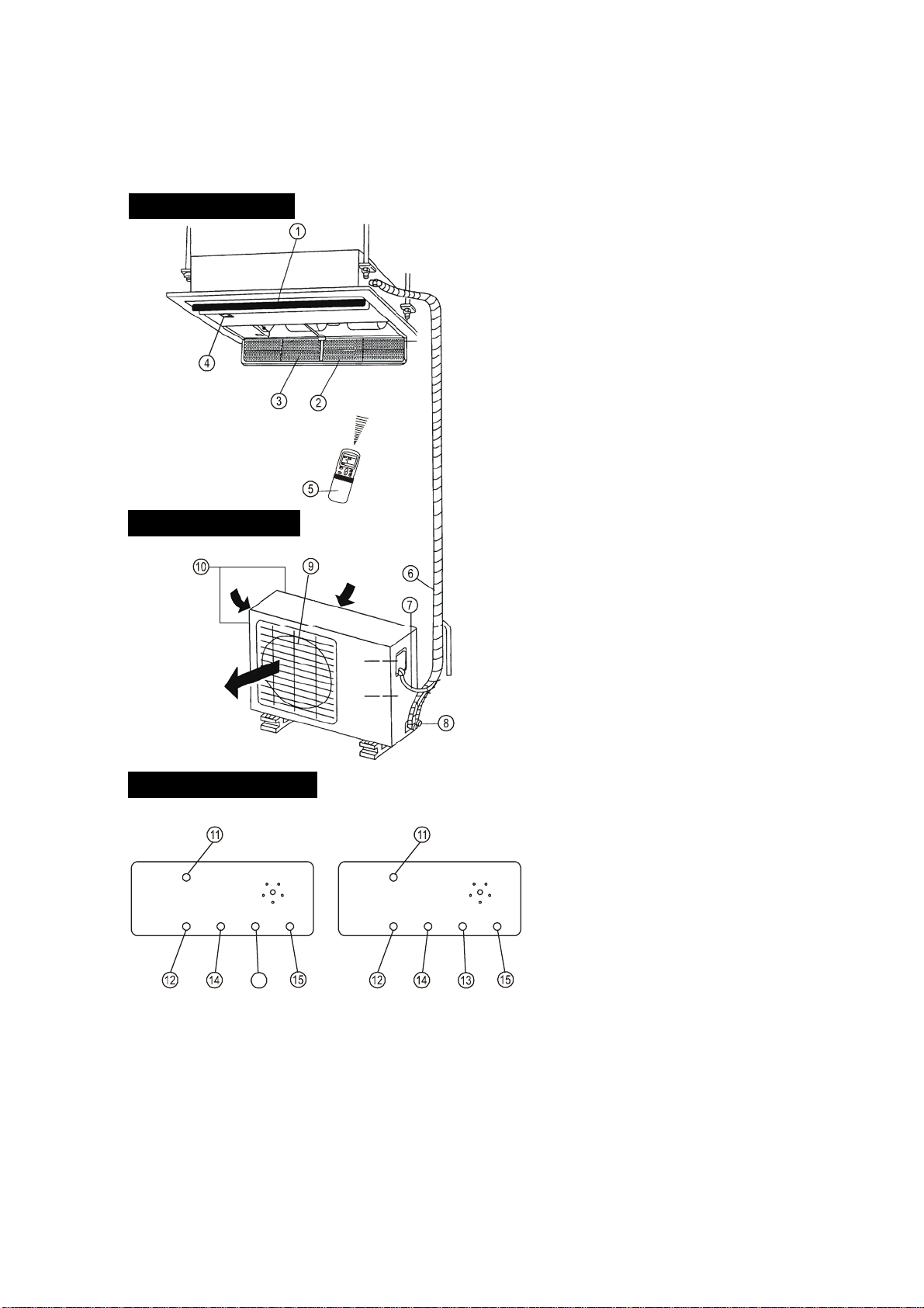
This picture is based on the type of 18000Btu/h, So the appearance and function may be
slightly different from the unit you purchased.
12 13 14 15
2
6
7
4
3
8
5
1
9
11
10
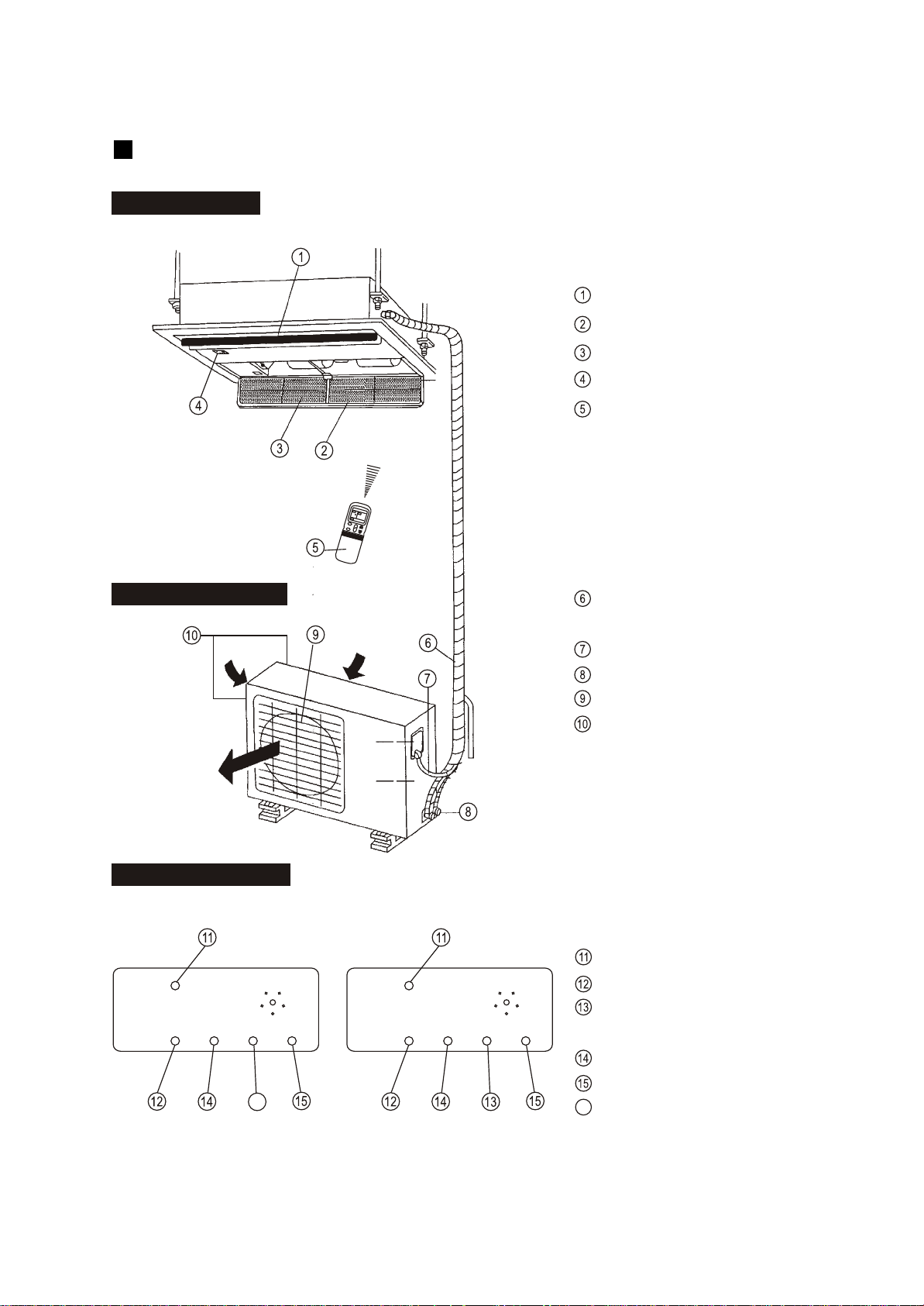
Indoor Unit Assy
Outdoor Unit Assy
Control board
Inlet
Outlet
Manual
OPERATION
TIMER
DEF./FAN.
ALARM
Indoor Unit
Air outlet
Drain hose
Drain Pump (Internal installed),water drain from indoor unit.
Infrared Signal receiver
Timer indicator
Alarm indicator
Defrost indicator heating/cooling type or fan indicator (cooling
only type)
Outdoor Unit
Vertical louver
Manual button
Remote Controller
Connecting pipe
Run lamp
1
7
10
4
9
13
15
2
3
Parts Names:
11 12
14
8
5
6
Air Inlet (Air filter installed inside to prevent the dust)
Four-way Cassette(slim) Type
7
OUTDOOR UNIT
Display panel
INDOOR UNIT
Outlet louver
Inlet
Filter
Display panel
Remote controller
Refrigerant connecting, drain
hose pipe
Electric wiring
Trap
Air outlet
Air inlet(side and rear)
MANUAL
RUN
FAN
TIMER
ALARM
inlet
TEMP
CLOCK
SPEED
C
MODE
FAN
I
O
TEMP
inlet
outlet
MANUAL
RUN
TIMER
DEF
ALARM
MANUAL
RUN
TIMER
FAN
ALARM
MANUAL button
Run lamp
FAN indicator(Cooling/Heating
type without)
TIMER indicator
ALARM indicator
DEF. indicator(Cooling-only type
without)
16
INDOOR UNIT
DISPLAY PANEL
OUTDOOR UNIT
16
One-way Cassette Type
8
Cooling-only typeCooling&Heating type
f
c
CC
g
Display Panel
NAMES AND FUNCTIONS
b
c
f
a
d
e
g
h
i
k
m
o
l
n
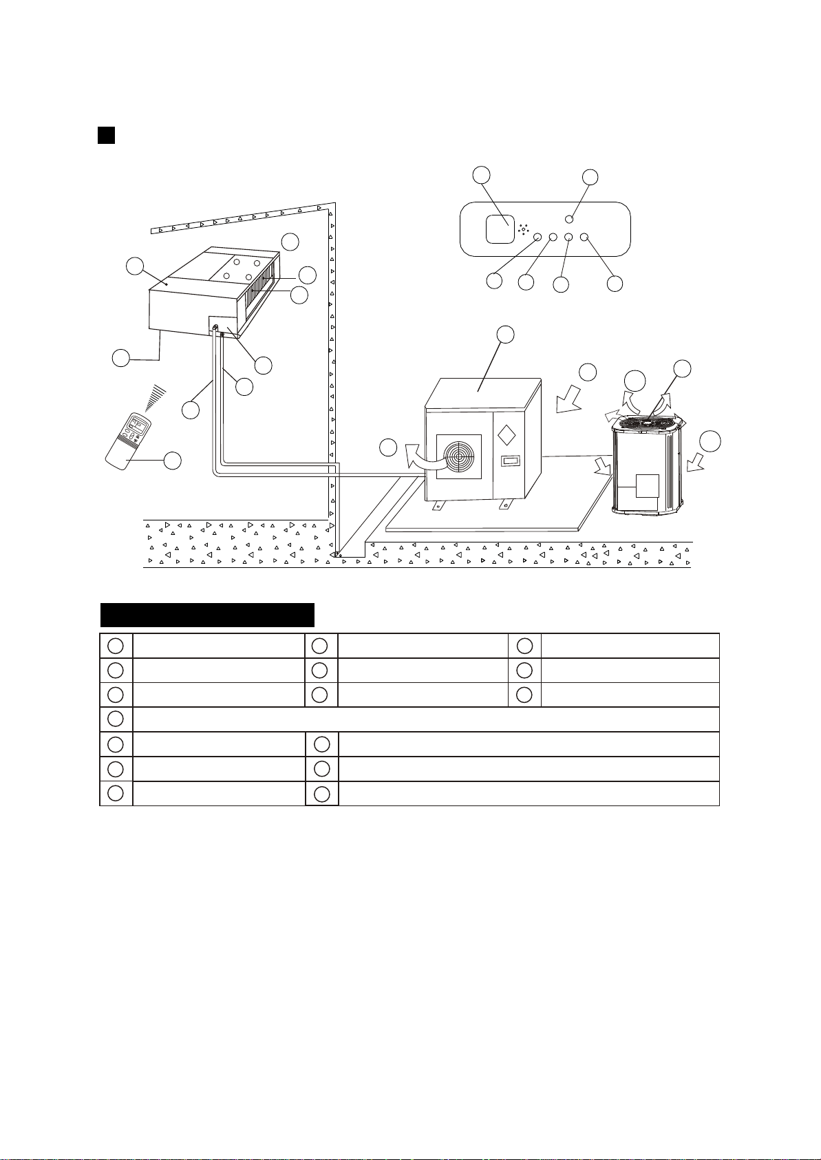
NOTICE!
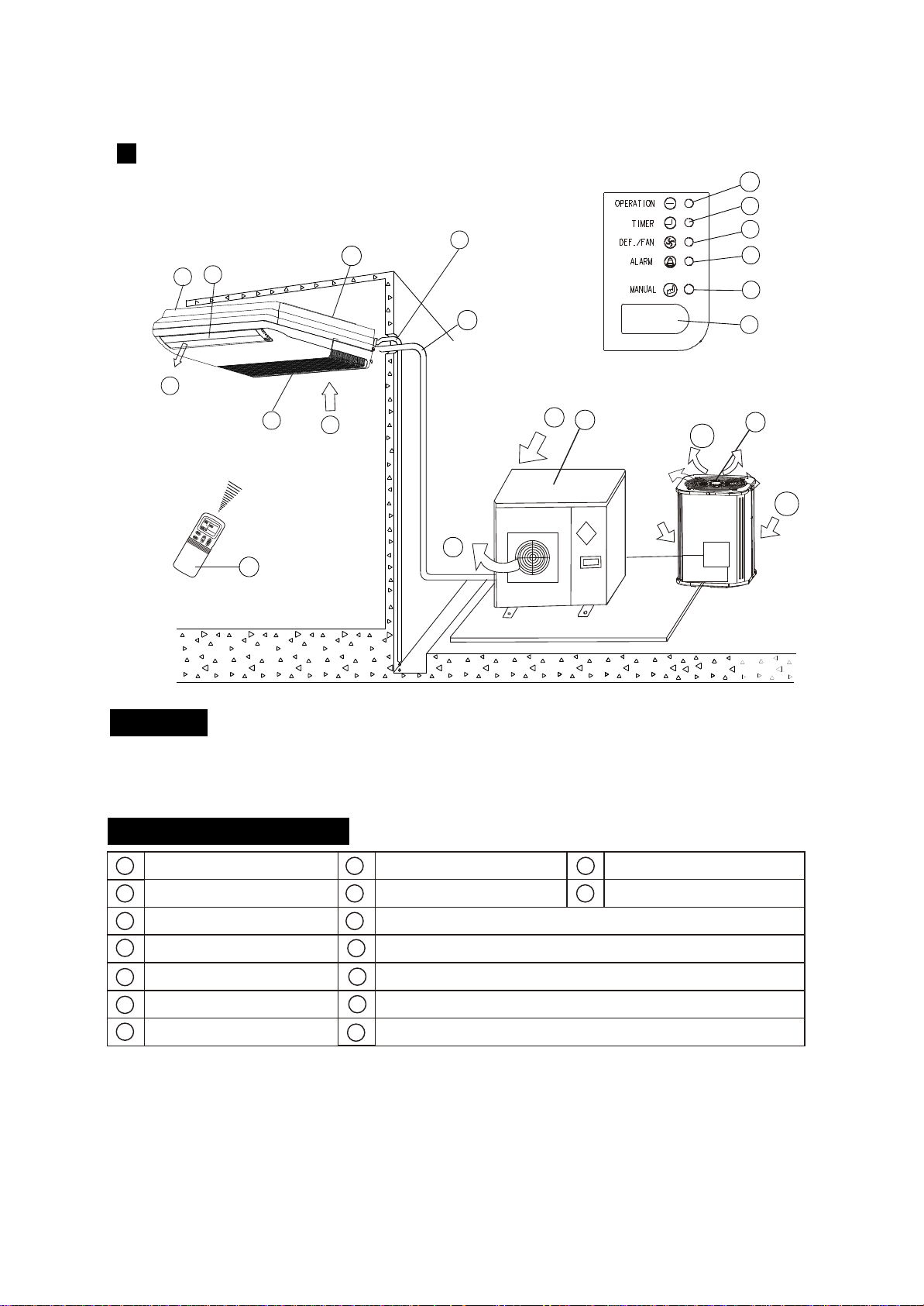
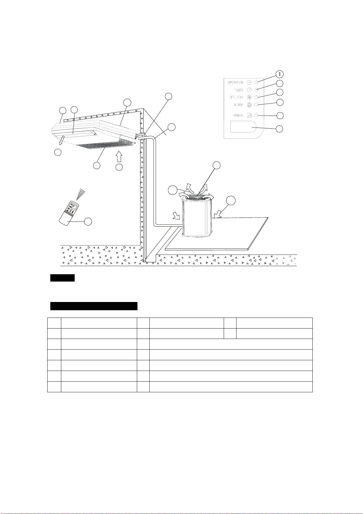
indoor unit
air-in
drain hose
outdoor unit
air flow louver (at air outlet)
air inlet (with air filter in it)
installation part
remote controller
connecting pipe
infrared signal receiver
operation lamp
timer indicator
temporary button
alarm
indicator
j
FAN/DEF indicator
,,
(For cooling and heating type, its D EF.,for cooling only type, its FAN)
P
air-out
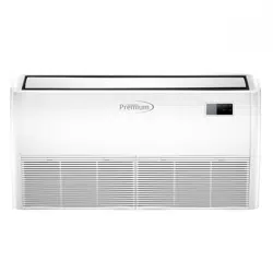
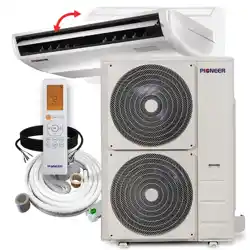
Ceiling & Floor Type(for )VERTICAL DISCHARGE AIR CONDITIONER
9
The chart based on one model of our product is for reference only, which may be different from
the unit you purchased.
n
m
o
l
k
J
i
a
e
d
h
p
b
d
p
b
d
p
or
f
c
CC
g
Display Panel
NAMES AND FUNCTIONS
b
c
f
a
d
e
g
h
i
k
m
o
l
n
NOTICE!
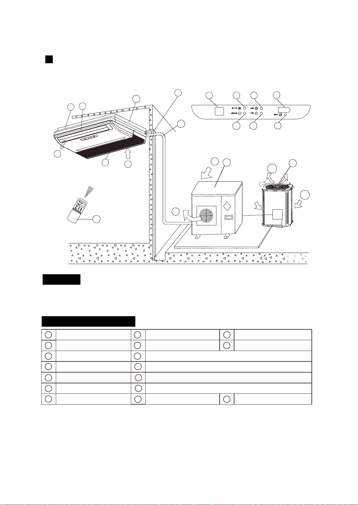
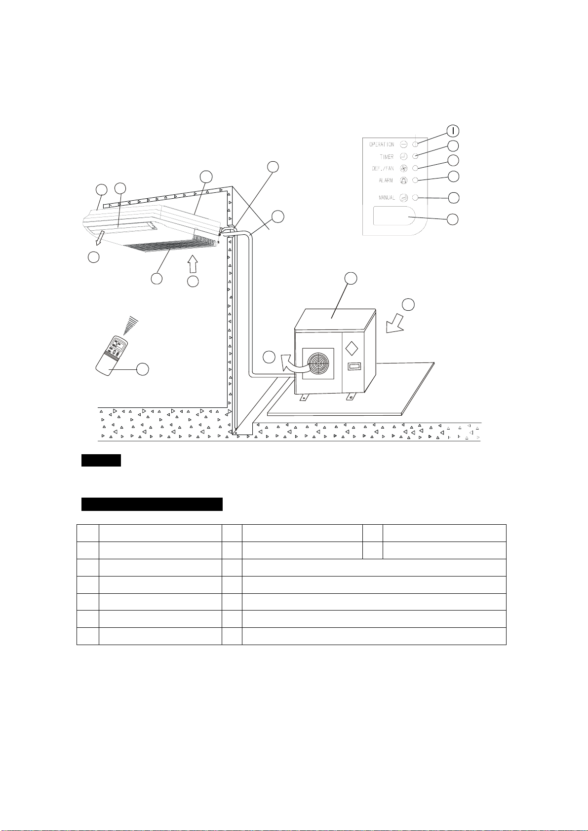
indoor unit
air-in
drain hose
outdoor unit
air flow louver (at air outlet)
air inlet (with air filter in it)
installation part
remote controller
connecting pipe
infrared signal receiver
operation lamp
timer indicator
temporary button
Alarm
Indicator
j
FAN/DEF indicator
,,
(For cooling and heating type, its D EF.,for cooling only type, its FAN)
P
air-out
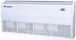
Ceiling & Floor Type
10
The chart based on one model of our product is for reference only, which may be different from
the unit you purchased.
i
a
e
d
h
p
b
d
p
n
m
o
l
k
Jq
q
Temperature display
b
d
p
or
f
c
CC
g
Display Panel
NAMES AND FUNCTIONS
b
c
f
a
d
e
g
h
i
k
m
o
l
n
NOTICE!
indoor unit
air-in
drain hose
outdoor unit
air flow louver (at air outlet)
air inlet (with air filter in it)
installation part
remote controller
connecting pipe
infrared signal receiver
operation lamp
timer indicator
temporary button
Alarm
Indicator
j
FAN/DEF indicator
,,
(For cooling and heating type, its D EF.,for cooling only type, its FAN)
P
air-out
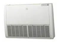
Ceiling & Floor Type
11
The chart based on one model of our product is for reference only, which may be different from
the unit you purchased.
i
a
e
d
h
p
b
d
p
q
Temperature display
b
d
p
or
o
k
l
m j
n
q
MANUALMANUAL
OPERATIONOPERATION
TIMERTIMER
DEF./FANDEF./FAN
ALARMALARM
f
i
n
m
o
c
CC
l
a
j
k
g
e
d
Display Panel
h
p
NAMES AND FUNCTIONS
b
c
f
a
d
e
g
h
i
k
m
o
l
n
NOTICE!
indoor unit
air-in
drain hose
outdoor unit
air flow louver (at air outlet)
air inlet (with air filter in it)
installation part
remote controller
connecting pipe
infrared signal receiver
operation lamp
timer indicator
temporary button
alarm
indicator
j
FAN/DEF indicator
,,
(For cooling and heating type, its D EF.,for cooling only type, its FAN)
P
air-out
Ceiling & Floor Type
12
The chart based on one model of our product is for reference only, which may be different from
the unit you purchased.
b
d
p
b
d
p
or
ADJUSTING AIR FLOW DIRECTION
Cassette Type
While the unit is in operation, you can adjust the air flow louver to change the flow direction and natu-
ralize the room temperature evenly. Thus you can enjoy it more comfortably.
1. Set the desired air flow direction.
Push the SWING button to adjust the louver to the desired position and push this button again to
maintain the louver at this position.
2. Adjust the air flow direction automatically.
Push the SWING button, the louver will swing automatically.
While this function is set, the swing fan of indoor unit runs; otherwise, the swing fan doesn't run. The
0
swing scale of every side is 30 . When the air conditioner isn't in operation (including when "TIMER
ON" is set), the SWING button will be disabled.
The following is how to adjust air flow direction when air outlet part (separately saled) is
used with the indoor unit.
Heating
To effectively heat the bottom of the room,
Please set the louver so that the air can
come out downwards.
Duct and Ceiling Type
Cooling
To effectively cool the whole room, please
set the louver so that the air can come out
horizontally.
ADJUST IT UP AND DOWN
13
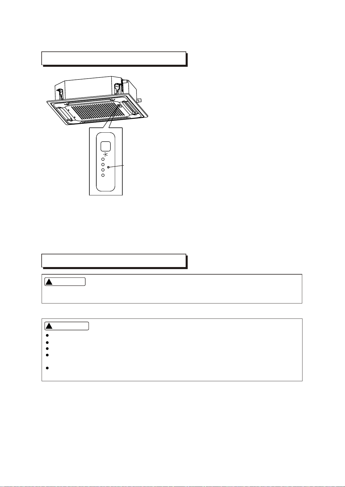
TEMPORARY OPERATIONS
MAINTENANCE
TEMPORARY
BUTTON
This function is used to operate the unit temporarily
in case you misplace the remote controller or its
batteries are exhausted. Two modes including AUTO
and mandatory COOL can be selected through the
TEMPORARY BUTTON on the air inlet grill control
box of the indoor unit. Once you push this button, the
air conditioner will run in such order: AUTO,
mandatory COOL, OFF, and back to AUTO.
1. AUTO
The OPERATION lamp is lit, and the air conditioner
will run under AUTO mode. The remote controller
operation is enabled to operate according to the
received signal.
2. mandatory COOL
The OPERATION lamp flashes, the air conditioner
will turn to AUTO after it is enforced to cool with a
wind speed of HIGH for 30 minutes. The remote
controller operation is disabled.
3. OFF
Note: Only take the cassette type as example.
The OPERATION lamp goes off. The air conditioner
is OFF while the remote controller operation is
enabled.
14
WARNING
Cleaning the indoor unit and remote controller
WARNING
Before you clean the air conditioner, be sure to disconnect the power supply plug.
If you do not plan to use the unit for at least 1 month.
(1) Operate the fan for about half a day to dry the inside of the unit.
(2) Stop the air conditioner and disconnect power.
(3) Remove the batteries from the remote controller.
!!
Use a dry cloth to wipe the indoor unit and remote controller.
A cloth dampened with cold water may be used on the indoor unit if it is very dirty.
Never use a damp cloth on the remote controller.
Do not use a chemically-treted duster for wiping or leave such material on the unit for long,
because it may damage or fade the surface of the unit.
Do not use benzine, thinner, polishing powder, or similar solvents for cleaning. These may
cause the plastic surface to crack or deform.
CAUTIONS
!!
Checks before operation
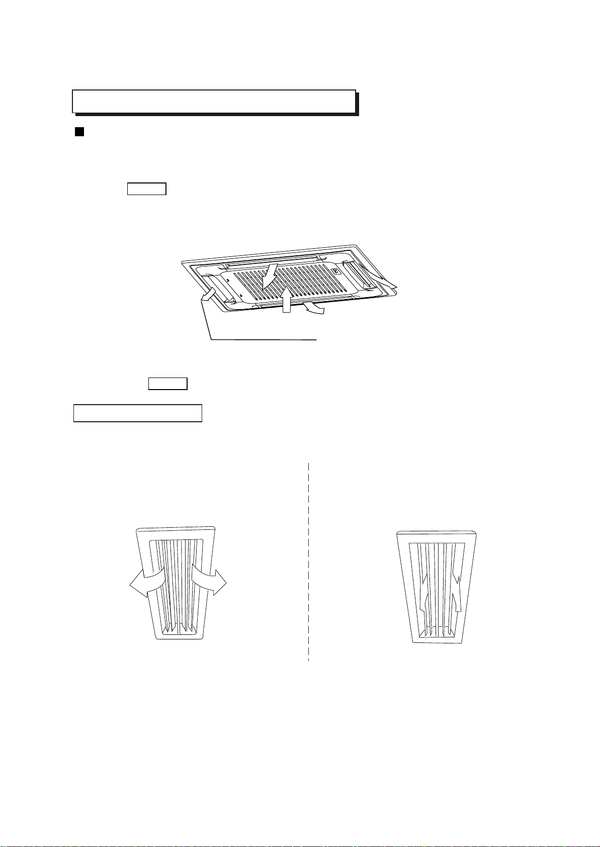
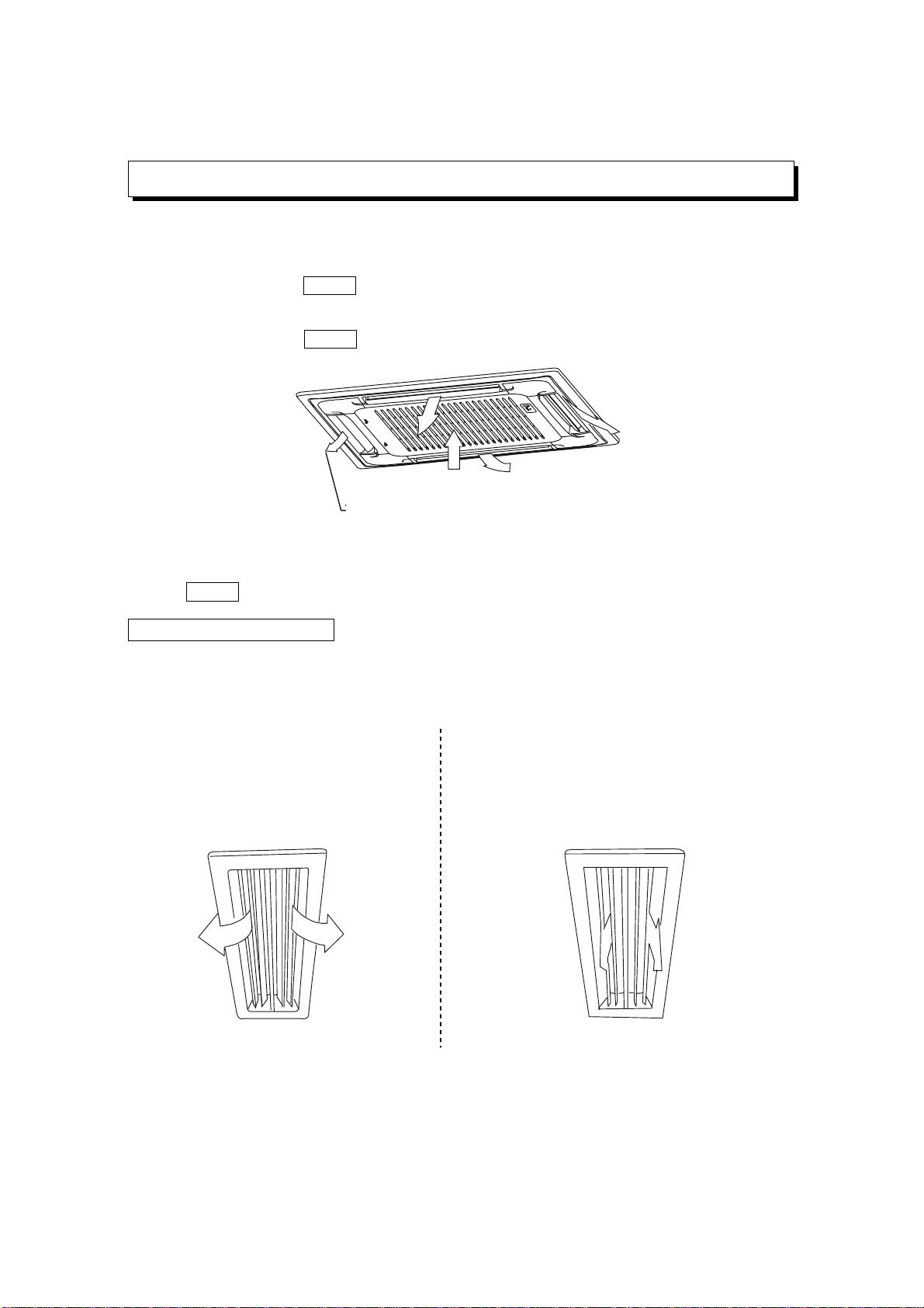
Cleaning the air filter
Check that the wiring is not broken off or disconnected.
Check that the air filter is installed. (Some air-conditioners haven't air filters.)
Check that the outdoor unit air outlet or inlet is not blocked.
Before you clean the air conditioner, be sure to disconnect the power supply plug.
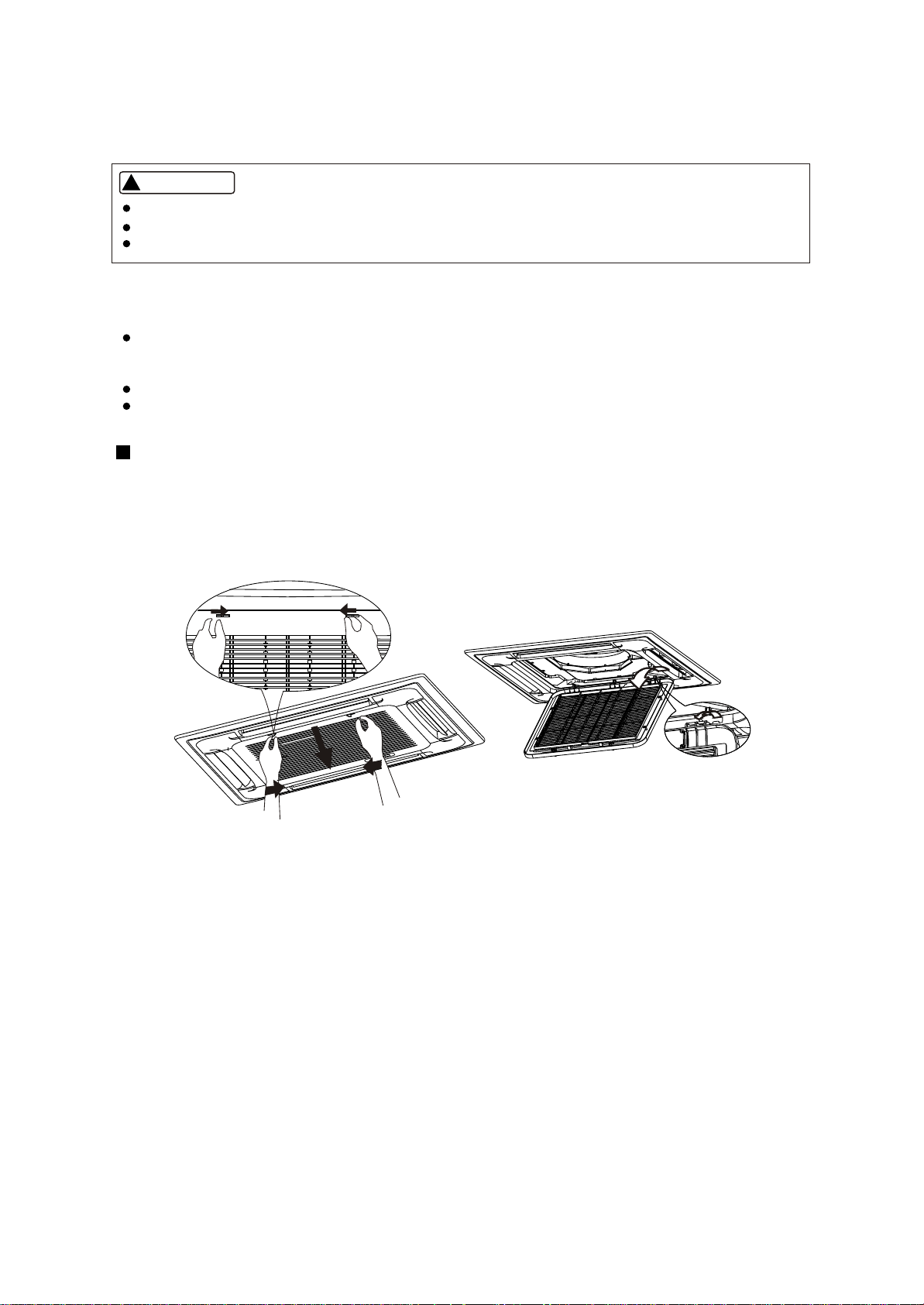
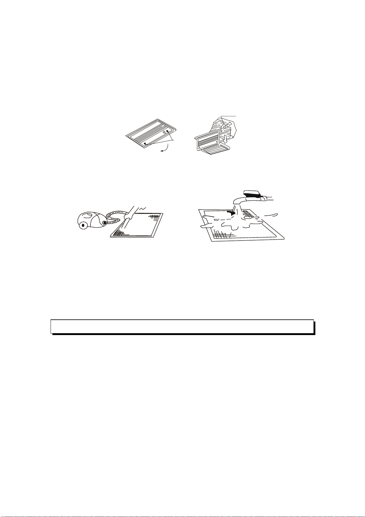
2. Take out the air-in grill (together with the air filter shown in Sketch B)
o
Pull the air-in grill down at 45 and lift it up to take out the grill.
3. Dismantle the air filter
4. Clean the air filter(Vacuum cleaner or pure water may be used to clean the air filter. If the dust
accumulation is too heavy , please use soft brush and mild detergent to clean it and dry out in cool
place) .
The air filter can prevent the dust or other particulate from going inside .In case of blockage of the filter , the
working efficiency of the air conditioner may greatly decrease .Therefore , the filter must be cleaned once two
weeks during long time usage.
If the air conditioner is positioned in a dust place , the cleaning frequency of the air filter must be increased .
If the accumulated dust is too heavy to be cleaned , please replace the filter with a new one(replaceable air
filter is an optional fitting).
A B
1. Open the air-in grill
Push the grill switches towards the middle simultaneously as indicated in sketch A. Then pull down
the air-in grill.
Cautions: The control box cables ,which are originally connected with the main body electrical terminators
must be pulled off before doing as indicated above.
Cassette Type
15
CAUTIONS
!!
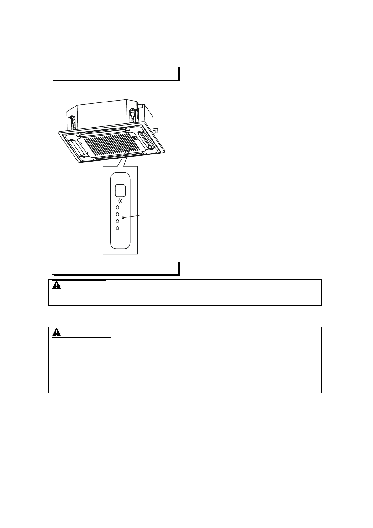
Duct and Ceiling Type
Three-minute protection feature
Power failure
A protection feature prevents the air conditioner from being activated for approximately 3 minutes
when it restarts immediately after operation.
Power failure during operation will stop the unit completely.
Disconnect the unit with the power and then connect the unit with the power again. Push the ON/OFF
button on the remote controller to restart operation.
The OPERATION lamp on the indoor unit will start flashing when power is restored.
To restart operation, push the ON/OFF button on the remote controller.
Lightning or a car wireless telephone operating nearby may cause the unit to malfunction.
Clip
Open<
2. Take out the air-in grill.
3. Dismantle the air filter
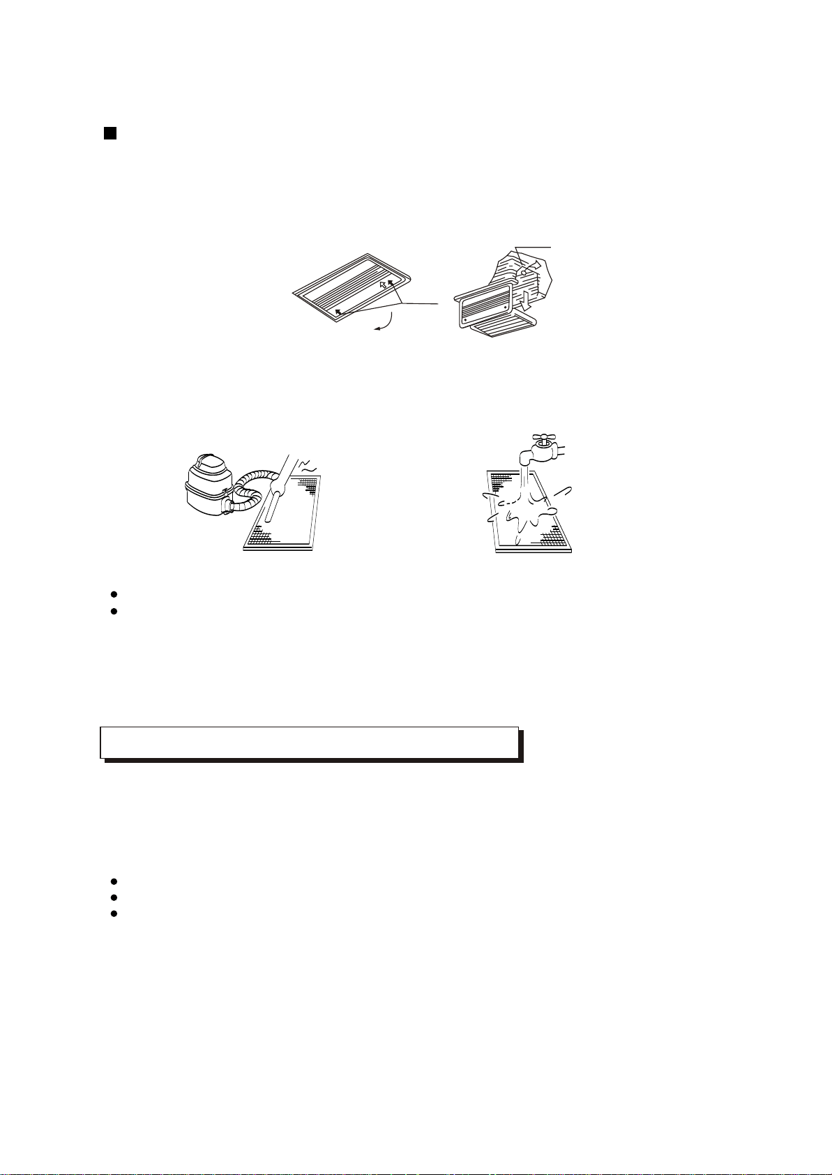
4. Clean the air filter (Vacuum cleaner or pure water may be used to clean the air filter. If the dust
accumulation is too heavy , please use soft brush and mild detergent to clean it and dry out in cool
place) .
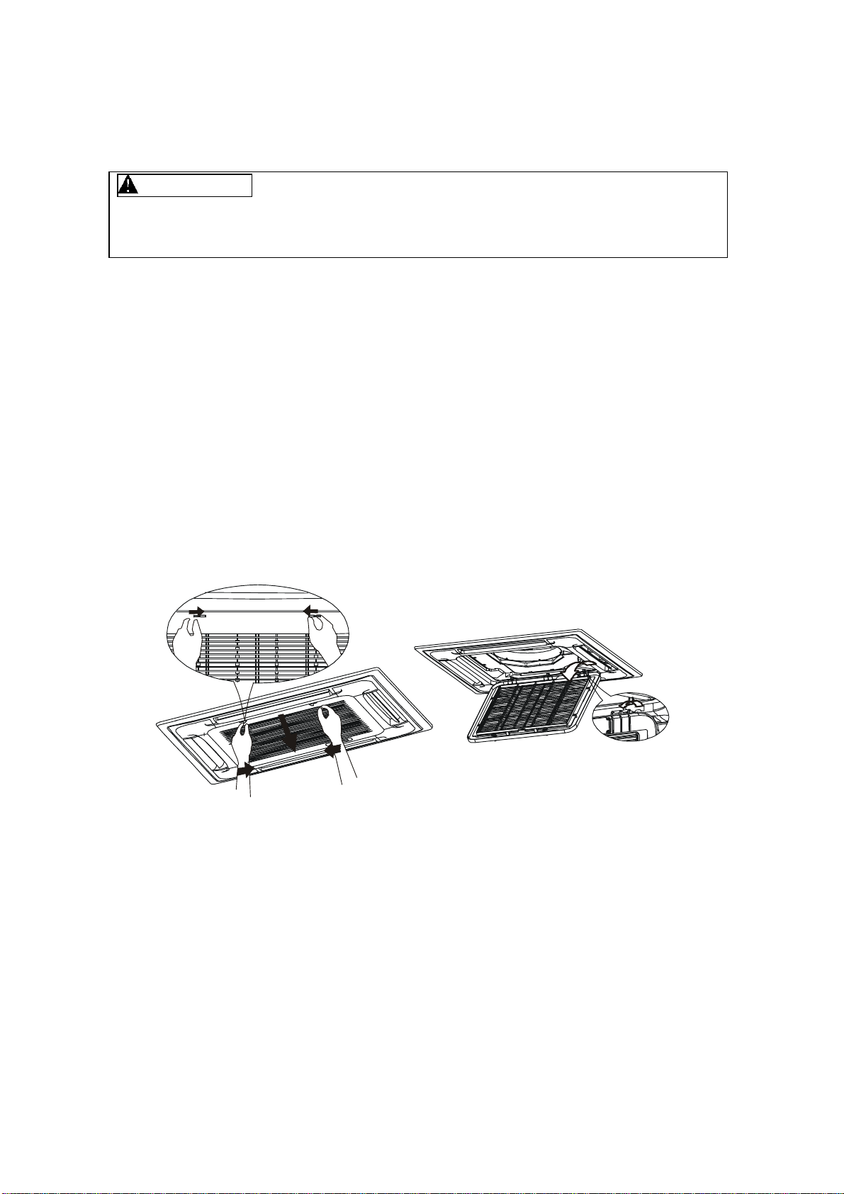
1. Open the air-in grill
Push the grill switches towards the middle simultaneously as indicated in follow figure sketch.
Then pull down the air-in grill.
Cautions: The control box cables ,which are originally connected with the main body electrical
terminators must be pulled off before doing as indicated above.
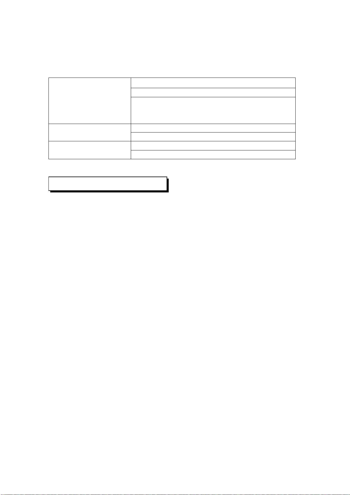
Fig. 1 Fig. 2
The air-in side should face up when using vacuum cleaner. (See Fig. 1)
The air-in side should face down when using water. (See Fig. 2)
Cautions : Do not dry out the air filter under direct sunshine or with fire.
5. Re-install the air filter
6. Install and close the air-in grill in the reverse order of step 1 and 2 and connect the control box
cables to the corresponding terminators of the main body .
Note: High-static Pressure Parvis Split Type has no air filter.
16
AIR CONDITIONER OPERATIONS AND PERFORMANCE
Air conditioner operating conditions
Relocation
For proper performance, run the air conditioner under the following temperature conditions:
If you move out or if it is desired to relocate the air conditioner, consult your dealer, because special
skills to withdraw Freon, purge air and perform other operations are required.
If air conditioner is used beyond the above conditions, safety protection features may come into
operation.
Cooling operation
oo
Outdoor temperature: 21 to 43 C or 21 to 52 C (T3 type)
o
Outdoor temperature: -5 to 24 C
oo
Outdoor temperature: 11 to 43C or 21 to 52 C (T3 type)
o
Room temperature: 17 to 32 C
o
Room temperature: 0 to 30 C
o
Room temperature: 17 to 30 C
CAUTION
Room relative humidity less than 80%. If the air conditioner
operates in excess of this figure, the surface of the air conditioner
may attract condensation.
Dry operation
Heating operating
(cooling only type without)
Location:
Be careful of noise or vibrations
Wire
During cooling operation, the air conditioner will dry the room air, so please fix a pipe to drain all the
water away from the air conditioner.
Please let the indoor unit more than one metre away from the TV set and the radio in order to avoid
the picture and noise interference.
Powerful radio transmitters or any other devices radiating high frequency radio waves can cause
the air conditioner to malfunction. Please consult the dealer where you purchased the air conditio-
ner before installing it.
Don't fix the unit in the dangerous region with combustible gas or volatile matter.
If the air conditioner operates in an atmosphere containing oils (machine oil), salt (near a coastal
area), sulfide gas (near a hot spring), etc., such substances may lead to failure of the air conditioner.
Please fix the unit in the stable place to avoid the noise or vibrations.
The noise near the air outlet of the outdoor unit may enter the air exit.
Locate the outdoor unit where noise emitted by it or hot air from its air outlet will cause no nuisance
to your neighbours.
If the air conditioner sounds abnormal during operation, contact the dealer where you purchased the
air conditioner.
To avoid the electric shock, please link the air conditioner with the ground. The plug in the air
conditioner has joined the ground wiring, please don't change it freely.
The power socket is used as the air conditioner specially.
Don't pull the power wiring hard.
When linking the air conditioner with the ground, observe the local rulers.
If necessary, use the power fuse or the circuit, breaker or the corresponding scale ampere.
If you want to change the power wiring, please contact the centre service of the local MD electric
appliance.
INSTALLATION
17
Before you ask for servicing or repairs, check the following points.
Setting Change is Impossible
Symptoms
Causes
Reason and Disposal
The fan speed can not be
changed.
Check whether the MODE
indicated on the display is
"AUTO"
Check whether the MODE
indicated on the display is
"DRY"
When the automatic mode is
selected, the air conditioner
automatically selects the fan
speed.
When dry operation is selected,
the air conditioner automatically
select the fan speed. The fan
speed can be selected during
"COOL" and "FAN ONLY", and
"HEAT"
TROUBLES AND CAUSES
(CONCERNING REMOTE CONTROLLER)
TROUBLES AND CAUSES
Before you ask for servicing or repairs, check the following points.
The power fuse is blown or the circuit breaker has been tripped.
The batteries in the remote controller are exhausted.
The timer is set.
A bad odor comes from the air conditioner.
The air inlet or outlet of the outdoor unit is blocked.
Doors or windows are open.
The air filter is clogged with dust.
The louver is not at the correct position.
The fan speed is set to low.
The temperature setting is too high or too low.
Smells impregnated in the wall, carpet, furniture, clothing, or furs, are coming out. A white mist
of chilled air or water is generated from the outdoor unit.
The indicator lamps flash rapidly (five times per second), you disconnect the unit with the power
and then connect the unit with the power again after two or three minutes but the lamps still flash.
Switch operations are erratic.
The fuse is blown frequently or the circuit breaker is tripped frequently.
Foreign matter or water has fallen inside the air conditioner.
Any other unusual condition is observed.
Recheck
These are not failures
Inoperative
Room air is smelly.
Does not cool or heat well.
If any of the following conditions occur, stop the air conditioner immediately, set to off the power
switch, and contact the dealer:
CAUTION
!!
18
The Transmission Indicator " " Never Comes On
The Display Never Comes On
Symptoms
Symptoms
Causes
Causes
Reason and Disposal
Reason
The remote control signal is
not transmitted even when
the ON/OFF button is pushed.
The TEMP. indicator does
not come on.
Check whether the batteries
in the remote controller are
exhausted.
Check whether the MODE
indicated on the display is
"FAN ONLY".
FAN ONLY
The remote control signal is
not transmitted, because the
power supply is off.
The temperature cannot be
set during fan only operation.
The Display Goes Off
Symptoms
Causes
Reason
The indication on the display
disappears after a lapse of
time.
The ON TIMER indicators
go off after a lapse of certain
time.
Check whether the timer
operation has come to an
end when the OFF TIMER
is indicated on the display.
Check whether the timer
operation is started when
the ON TIMER is indicated
on the display.
The air conditioner operation
stops since the set time
elapsed.
When the time set to start the
air conditioner is reached, the
air conditioner will automatically
start and the appropriate
indicator will go off.
The Signal Receiving Tone does Not Sound
Symptoms
Causes
Disposal
No receiving tone sounds
from the indoor unit even
when the ON/OFF button is
pushed.
Check whether the signal
transmitter of the remote
controller is properly directed
to the receiver of the indoor
unit when the ON/OFF button
is pushed.
Direct the signal transmitter of
the remote controller to the
receiver of the indoor unit, and
then repeatly push the ON/
OFF button twice.
Buttons on the remote
controller don't work.
Press Reset button.
19
ACONDICIONADOR DE AIRE
MANUAL DE USUARIO
Modelo:PAC366FC
PAC606FC
PAC486FC
PAC3663FC
PAC4863FC
PAC4873C
PAC6063FC

CONTENIDO .
INFORMACION IMPORTANTE DE SEGURIDAD---------------------------------------------------1
SUGERENCIAS PARA UN FUNCIONAMIENTO ECONOMICO---------------------------------2
NOMBRES DE LAS PARTES-----------------------------------------------------------------------------2
AJUSTES EN EL DIRECCIONAMIENTO DEL FLUJO DE AIRE-------------------------------12
FUNCIONAMIENTO TRMPORARIO--- ---------------------------------------------------------------13
MANTENIMIENTO------------------------------------------------------------------------------------------13
FUNCIONES DE ACONDICIONADOR DE AIRE Y PERFORMANCE------------------------15
INSTALACION-----------------------------------------------------------------------------------------------16
PROBLEMAS Y CAUSAS---------------------------------------------------------------------------------17
PROBLEMAS Y CAUSAS (REFERIDAS AL CONTROL REMOTO) --------------------------17
No
Thinner
PRECAUCION
No intente instalar este equipo Usted mismo. Esta unidad requiere ser
instalada por personas calificadas para ello.
PELIGRO
No intente realizar Ud. mismo tareas de servicio o reparaciones. Esta
unidad no tiene partes útiles para el usuario. El abrir o quitar la tapa lo
expondrá a tensiones peligrosas. El apagar el interruptor de
encendido no es prevención contra potenciales descargas eléctricas.
PELIGRO
Nunca ponga sus manos u objetos dentro de las salidas de aire de las
unidades interior o exterior. Estas unidades están provistas con
ventiladores que giran a alta velocidad. Tocar las partes en
movimiento causará serias lesiones.
PELIGRO
A fin de evitar serios riesgos de descargas eléctricas, nunca rocíe o
derrame agua u otros líquidos sobre el equipo.
AVISO
Ventile la habitación regularmente mientras el acondicionador de aire
se está usando, especialmente si hay además en uso un artefacto a
gas en la misma habitación.
Una falla en seguir estas indicaciones puede resultar en una
disminución del oxígeno en la habitación.
ADVERTENCIA
Para prevenir descargas eléctricas, apague la alimentación eléctrica
al aparato o desconéctelo del tomacorrientes antes de comenzar con
la limpieza u otra rutina de mantenimiento. Siga las instrucciones de
limpieza dadas en este manual.
ADVERTENCIA
No use líquidos o aerosoles limpiadores, use un paño seco y suave
para su limpieza. Para evitar riesgos de descargas eléctricas, nunca
intente limpiar las unidades rociándolas con agua.
PRECAUCION
No use limpiadores líquidos cáusticos de uso doméstico en las
unidades. El drenaje de estos limpiadores puede destruir
rápidamente componentes del equipo. (bandeja de drenaje,
y arrollamientos del intercambiador de calor, etc.).
NOTA
Para un adecuado rendimiento, haga funcionar esta unidad en los rangos de temperatura y
humedad indicados en este manual. Si el equipo es operado mas allá de esas condiciones, esto puede causar
malfuncionamiento o pérdidas de agua desde la unidad.
1
Peligro
No
Limpiador
Líquido
IMPORTANTE INFORMACION DE SEGURIDAD
Para asegurarse un funcionamiento económico, debe tenerse en cuenta lo que sigue (Para detalles, referirse a
los capítulos correspondientes)
• Ajuste la dirección del flujo de aire adecuadamente para evitar direccionarlo sobre su cuerpo.
• Ajuste la temperatura del ambiente a un nivel confortable y evite sobreenfriamiento y sobrecalentamiento.
• En función frío, cierre los cortinados para impedir el paso directo de la luz solar.
• Para conservar el aire frío o caliente dentro de la habitación, nunca abra las puertas o ventanas más de lo
necesario.
• Programe el temporizador para el tiempo de funcionamiento deseado.
• No coloque nunca obstrucciones cerca de las salidas o entradas de aire. Esto causará baja eficiencia o
hasta una inesperada detención de la unidad.
• Si Usted no piensa usar el equipo durante un tiempo prolongado, desconecte la alimentación y retire las
pilas del control remoto. Cuando el control de encendido está en Sí, consumirá algo de energía, aún
cuando el equipo no esté en uso. Por lo tanto desconecte la alimentación para ahorrar energía. Cuando
vaya a arrancar de nuevo el equipo, enciéndalo 12 horas antes para asegurarse un funcionamiento
uniforme.
• Un filtro de aire sucio u obstruido reduce la eficiencia tanto en refrigeración como en calefacción, por lo
que debe limpiarse una vez cada dos semanas.
El acondicionador de aire consiste en la unidad interior y la unidad exterior, la cañería de interconexión y el
control remoto.
Tipo Cassette
AVISO !
Esta ilustración está basada en el tipo de 6000 kCal/h (24000Btu/h). Por lo que pueden existir pequeñas
diferencias en el aspecto y las funciones respecto del suyo.
2
f
b
d
e
i
m
n
p
o
c
Panel de Control
SUGERENCIAS PARA UN FUNCIONAMIENTO ECONOMICO
NOMBRES DE LAS PARTES
a) unidad interior b) unidad exterior
c) control remoto d) entrada de aire
e) salida de aire f ) salida de aire
g) persiana de la salida de aire h) cañería de interconexión
i ) manguera de drenaje j ) entrada de aire (con filtro colocado)
k) bomba de drenaje (drena agua de la unidad interior) l ) receptor de las señales infrarrojas
m) botón temporario n) lámpara piloto
o) indicador del temporizador
p) indicador PRE-DEF (tipo frío y calor) o indicador de ventilación (en tipo frío solamente)
q) indicador de alarma
Tipo Split Pascal de Alta Presión Estática
AVISO !
Esta ilustración está basada en el tipo de 6000 kCal/h (24000Btu/h). Por lo que pueden existir pequeñas
diferencias en el aspecto y las funciones respecto del suyo.
NOMBRES Y FUNCIONESFF
ⓐ
Unidad interior
ⓑ
Unidad exterior
ⓒ
Control remoto
ⓓ
Entrada de aire
ⓔ
Salida de aire
ⓕ
Salida de aire
ⓖ
Intercambiador de calor
ⓗ
Cañería de interconexión
ⓘ
Manguera de drenaje
ⓙ
Caja-E
ⓚ
Receptor infrarrojo
ⓛ
Botón temporario
ⓜ
Lámpara piloto
ⓞ
Indicador PRE-DEF (tipo frío-calor) o indicador ventilación (tipo frío solo)
ⓝ
Indicador del temporizador
ⓟ
Indicador de alarma
3
NOMBRES Y FUNCIONES
Panel de control
Tipo Ducto y Cielorraso
h
b
f
d
d
e
i
m
n
p
o
c
a
g
k
AVISO !
Esta ilustración está basada en el tipo de 6000 kCal/h (24000Btu/h). Por lo que pueden existir pequeñas
diferencias en el aspecto y las funciones respecto del suyo.
NOMBRES Y FUNCIONESFF
ⓐ
Unidad interior
ⓑ
Unidad exterior
ⓒ
Control remoto
ⓓ
Entrada de aire
ⓔ
Salida de aire
ⓕ
Salida de aire
ⓖ
Persiana salida de aire
ⓗ
Cañería de interconexión
ⓘ
Manguera de drenaje
ⓙ
Entrada de aire – con filtro
ⓚ
Receptor infrarrojo
ⓛ
Botón manual
ⓜ
Lámpara piloto
ⓞ
Indicador PRE-DEF (tipo frío-calor) o indicador ventilación (tipo frío solo)
ⓝ
Indicador del temporizador
ⓟ
Indicador de alarma
4
Panel de Control
Tipo Ducto Baja Silueta
f
b
d
e
i
m
n
p
o
c
a
Display Panel
h
g
k
j
AVISO !
Esta ilustración está basada en el tipo de 6000 kCal/h (24000Btu/h). Por lo que pueden existir pequeñas
diferencias en el aspecto y las funciones respecto del suyo.
NOMBRES Y FUNCIONESFF
ⓐ
Unidad interior
ⓑ
Unidad exterior
ⓒ
Control remoto
ⓓ
Entrada de aire
ⓔ
Salida de aire
ⓕ
Salida de aire
ⓖⓗ
Cañería de interconexión
ⓘ
Manguera de drenaje
ⓙ
Caja-E
ⓚ
Receptor infrarrojo
ⓛ
Botón temporario
ⓜ
Lámpara piloto
ⓞ
Indicador PRE-DEF (tipo frío-calor) o indicador ventilación (tipo frío solo)
ⓝ
Indicador del temporizador
ⓟ
Indicador de alarma
5
Panel de Control
Tipo Ducto Baja Silueta con Caja de Entrada de Aire
h
b
d
e
i
m
n
p
o
c
ÎÂ
¶È
ʱ
ÖÓ
·ç
ËÙ
Ä£
ʽ
·ç
ËÙ
¿ª
¹Ø
×Ô
¶¯
C
k
f
d
a
f
g
Display Panel
AVISO !
Esta ilustración está basada en el tipo de 6000 kCal/h (24000Btu/h). Por lo que pueden existir pequeñas
diferencias en el aspecto y las funciones respecto del suyo.
NOMBRES Y FUNCIONESFF
ⓐ
Unidad interior
ⓑ
Unidad exterior
ⓒ
Control remoto
ⓓ
Entrada de aire
ⓔ
Salida de aire
ⓕ
Entrada de aire
ⓖ
Intercambiador de calor
ⓗ
Cañería de interconexión
ⓘ
Manguera de drenaje
ⓙ
Caja-E
ⓚ
Receptor infrarrojo
ⓛ
Botón temporario
ⓜ
Lámpara piloto
ⓝ
Indicador del temporizador
ⓟ
Indicador de alarma
ⓞ
Indicador PRE-DEF (tipo frío-calor) o indicador ventilación (tipo frío solo)
6
Panel de control
Tipo Cassette de Cuatro-vías (delgado)
Unidad Interior
AVISO !
Esta ilustración está basada en el tipo de 4500 kCal/h (18000Btu/h). Por lo que pueden existir pequeñas
diferencias en el aspecto y las funciones respecto del suyo.
NOMBRES Y FUNCIONESF
Unidad interior
②
Unidad exterior
③
Control remoto
④
Salida de aire
⑤
Persiana vertical
⑥
Cañería de interconexión
⑦
Manguera de drenaje
⑧
Entrada de aire (Filtro de aire colocado para prevenir suciedad)
⑨
Bomba de drenaje (expulsa el agua de condensación de la unidad interior)
⑩
Sensor Remoto
⑪
Botón Manual
⑫
Lámpara piloto
⑬
Indicador del temporizador
⑭
Indicador de descongelado tipo frío/calor o indicador de ventilador
(solamente tipo frío solo)
⑮
Indicador de alarma
7
Panel de control
Entrada
Salida
Unidad Exterior
Tipo Cassette de una vía
8
entrada
entrada
salida
MANUAL
RUN
TIME
R
DEF
ALARM
MANUAL
RUN
TIME
R
FAN
ALARM
16
PANEL DE CONTROL
UNIDAD EXTERIOR
16
Tipo frío soloTipo Frío
y
Calo
r
UNIDAD INTERIOR
UNIDAD INTERIOR
1) Parrilla de salida
2) Entrada
3) Filtro
4) Panel de control
5) Control remoto
UNIDAD EXTERIOR
6) Sistema de interconexión,
refrigerante, drenaje, cableado
eléctrico.
7) Cableado eléctrico
8) Boca
9) Salida de aire
10) Entrada de aire (lateral y
posterior)
PANEL DE CONTROL
11) Botón MANUAL
12) Lámpara piloto
13) Indicador de ventilador (tipo Frío
solo)
14) Indicador del temporizador
15) Indicador de alarma
16) Indicador DEF. (Tipo Frío solo)
Tipo Piso Techo (CONDENSADORA CON DESCARGA DE AIRE VERTICAL)
f
b
c
g
Display Panel
d
p
n
m
o
k
J
i
a
e
d
h
p
AVISO !
Esta ilustración está basada en un modelo de nuestros productos y es solamente para referencia, por lo cual
puede ser diferente de la unidad que Usted compró.
NOMBRES Y FUNCIONESF
ⓐ
Unidad interior
ⓑ
Unidad exterior
ⓒ
Control remoto
ⓓ
Entrada de aire
ⓔ
Deflectores de salida de aire
ⓕ
Cañería de interconexión
ⓖ
Manguera de drenaje
ⓗ
Ingreso de aire (a través del filtro colocado)
ⓘ
Partes de instalación
ⓙ
Indicador FAN-DEF (para tipo frío-calor, es DEF; para frío solo, es FAN)
ⓚ
Receptor infrarrojo
ⓛ
Lámpara piloto
ⓜ
Indicador temporario
ⓝ
Indicador de alarma
ⓞ
Indicador del temporizador
ⓟ
Salida de aire
9
Panel de Control
Tipo Piso Techo
f
c
g
Display Panel
n
m
o
k
J
i
a
e
d
h
p
b
d
p
AVISO !
Esta ilustración está basada en un modelo de nuestros productos y es solamente para referencia, por lo cual
puede ser diferente de la unidad que Usted compró.
NOMBRES Y FUNCIONES
F
ⓐ
Unidad interior
ⓑ
Unidad exterior
ⓒ
Control remoto
ⓓ
Entrada de aire
ⓔ
Deflectores de salida de aire
ⓕ
Cañería de interconexión
ⓖ
Manguera de drenaje
ⓗ
Ingreso de aire (a través del filtro colocado)
ⓘ
Partes de instalación
ⓙ
Indicador FAN-DEF (para tipo frío-calor, es DEF; para frío solo, es FAN)
ⓚ
Receptor infrarrojo
ⓛ
Lámpara piloto
ⓜ
Indicador del temporizador
ⓝ
Indicador de alarma
ⓞ
Indicador temporario
ⓟ
Salida de aire
10
Panel de Control
Tipo Piso Techo
f
b
d
p
i
n
m
o
c
a
k
g
e
d
Display Panel
h
p
AVISO !
Esta ilustración está basada en un modelo de nuestros productos y es solamente para referencia, por
lo cual puede ser diferente de la unidad que Usted compró.
NOMBRES Y FUNCIONES
ⓐ
Unidad interior
ⓑ
Unidad exterior
ⓒ
Control remoto
ⓓ
Entrada de aire
ⓔ
Deflectores de salida de aire
ⓕ
Cañería de interconexión
ⓖ
Manguera de drenaje
ⓗ
Ingreso de aire (a través del filtro colocado)
ⓘ
Partes de instalación
ⓙ
Indicador FAN-DEF (para tipo frío-calor, es DEF; para frío solo, es FAN)
ⓚ
Receptor infrarrojo
ⓛ
Lámpara piloto
ⓜ
Indicador del temporizador
ⓝ
Indicador de alarma
ⓞ
Indicador temporario
ⓟ
Salida de aire
11
Panel de Control
Mientras que la unidad está funcionando, Usted puede ajustar los deflectores para modificar la
dirección del flujo de aire para climatizar el ambiente de manera uniforme. De este modo Usted
puede disfrutarlo más agradablemente.
1. Seleccione la dirección del flujo de aire deseada
Presione el botón SWING para ajustar los deflectores a la posición deseada y presionando
este botón nuevamente, los deflectores se mantendrán en esa posición.
2. Movimiento automático del flujo de aire.
Presione el botón SWING, los deflectores se moverán automáticamente.
ADJUST IT UP AND DOWN
Mientras esta función está habilitada, los deflectores de la unidad interior oscilarán; de otra manera
éstos no funcionarán. La escala del vaivén es de 30º de cada lado. Cuando el acondicionador de
aire no está en funcionamiento (incluyendo cuando se programa el encendido por el temporizador),
el botón SWING será desactivado.
Tipo Ducto y Cielorraso
Lo siguiente muestra cómo ajustar la dirección del flujo de aire cuando una persiana de
salida de aire (vendida separadamente) es usada con la unidad interior.
Refrigeración Calefacción
Para enfriar efectivamente toda la Para calentar efectivamente la parte de
habitación, posicione los deflectores de abajo de la habitación, posicione los
manera que el aire pueda salir deflectores de manera que el flujo de
horizontalmente. aire pueda salir directamente hacia abajo.
12
AJUSTE DE LA DIRECCION DEL FLUJO DE AIRE
(
Ti
p
o Cassette
)
AJUSTELOS HACIA ARRIBA Y HACIA ABAJO
S
Esta opción es usada para hacer funcionar la unidad
temporariamente en caso de que Usted haya extraviado el
control remoto o sus pilas estén agotadas. Dos modos,
incluyendo AUTO y FRIO forzado pueden ser
seleccionados mediante el BOTON TEMPORARIO,
ubicado en la caja de control en la rejilla de entrada de aire
de la unidad interior. Una vez que Usted presione este
botón, el equipo funcionará en este orden: AUTO, FRIO
forzado, APAGADO, y vuelta a AUTO.
1. AUTO
El indicador de Funcionamiento se enciende, y el
acondicionador de aire funcionará en el modo AUTO. La
posibilidad de funcionar de acuerdo a las señales
recibidas desde el control remoto queda habilitada.
2. FRIO Forzado
El indicador de funcionamiento titila, el acondicionador de
aire irá a la función AUTO luego de que es forzado a
enfriar con el ventilador en la posición más alta (high)
durante 30 minutos. La posibilidad de comandar desde el
control remoto queda desactivada.
3. APAGADO (OFF)
El indicador de funcionamiento se apaga. El
acondicionador de aire queda apagado al tiempo que se
habilita la función de comando desde el control remoto.
Nota: Solo se tomó el tipo Cassette como ejemplo.
ADVERTENCIA
Antes de limpiar el acondicionador de aire, asegúrese de que está desenchufado de la línea de
alimentación.
Limpieza de la unidad interior y el control remoto
PRECAUCIONES
• Para limpiar la unidad interior y el control remoto, use un paño suave y seco
• Si la unidad interior está muy sucia, puede usarse un paño humedecido con agua fría.
• Nunca use una tela húmeda sobre el control remoto.
• No use un plumero con tratamientos químicos para frotar la unidad ni deje tal material sobre la
misma.
• No use bencina, thinner, pasta de pulir, o solventes similares para la limpieza. Esos elementos
pueden causar rotura o deformación en las partes plásticas.
Si Usted no piensa usar el equipo por al menos un mes,
(1) Haga funcionar solo el ventilador aproximadamente durante medio día, para secar el interior de
la unidad.
(2) Apague el acondicionador de aire y desenchúfelo de la línea de alimentación.
(3) Quite las pilas del control remoto.
13
TEMPORARY
BUTTON
FUNCIONES TEMPORARIAS
BOTON
TEMPORARIO
MANTENIMIENTO
Chequeos antes de ponerlo en funcionamiento
PRECAUCIONES
• Revise que el cableado no esté dañado o desconectado.
• Asegúrese de que el filtro de aire esté colocado. (algunos acondicionadores no tienen filtros)
• Verifique que las entradas y salidas de aire de la unidad exterior no estén obstruidas.
Antes de limpiar el acondicionador de aire, asegúrese de que está desenchufado de la línea de
alimentación.
Limpieza del filtro de aire
• El filtro de aire previene que el polvo y otras partículas ingresen al interior del aparato. En caso de
taponamiento del filtro, la eficiencia en el trabajo del acondicionador de aire puede disminuir
significativamente. Por lo tanto, el filtro debe ser limpiado una vez cada dos semanas en períodos de uso
intenso.
• Si el acondicionador de aire está colocado en un lugar polvoriento, la frecuencia de la limpieza del filtro de
aire debe incrementarse.
• Si la suciedad acumulada es demasiada para ser limpiada, entonces el filtro de aire debe ser reemplazado
por uno nuevo. (el uso de filtros reemplazables es una opción apropiada)
Tipo Cassette
1. Abra la rejilla de entrada de aire
Presione las trabas de la rejilla simultáneamente hacia el medio, como se indica en la ilustración A.
Luego tire hacia abajo la rejilla de entrada de aire.
Precauciones: Los cables de la caja de control, los cuales están originalmente conectados con los
terminales eléctricos del cuerpo principal, deben ser tirados hacia afuera antes de hacer lo que se indica
arriba.
A
B
2. Saque hacia afuera la rejilla de entrada de aire (juntamente con el filtro de aire mostrado en la
ilustración B)
Baje la rejilla de entrada de aire hasta un ángulo de 45º y levántela en su parte de atrás para
retirarla.
3. Retire el filtro de aire
4. Limpie el filtro de aire (para limpiar el filtro puede usarse una aspiradora o agua sola. Si la
acumulación de suciedad es muy pesada o densa, use un cepillo suave y detergente diluido
para limpiarlo; luego déjelo secar en un lugar frío y a la sombra).
14
Tipo Ducto y Cielorraso
1. Abra la rejilla de entrada de aire
Presione las trabas de la rejilla simultáneamente hacia el medio, como se indica en la ilustración
A. Luego tire hacia abajo la rejilla de entrada de aire.
Precauciones: Los cables de la caja de control, los cuales están originalmente conectados con los
terminales eléctricos del cuerpo principal, deben ser tirados hacia afuera antes de hacer lo que se indica
arriba.
Clip
Open<
2. Retire la rejilla de entrada de aire.
3. Quite el filtro de aire.
4. Limpie el filtro de aire (para limpiar el filtro puede usarse una aspiradora o agua sola. Si la
acumulación de suciedad es muy pesada o densa, use un cepillo suave y detergente diluido
para limpiarlo; luego déjelo secar en un lugar frío y a la sombra).
Fig. 1 Fig. 2
• El lado de la entrada de aire debe estar hacia arriba cuando se limpie con una aspiradora.
(Ver Fig. 1)
• El lado de la entrada de aire debe estar hacia abajo cuando se use agua. (Ver Fig. 2)
Precauciones: No seque el filtro de aire bajo la luz directa del sol o con fuego.
5. Coloque nuevamente el filtro de aire.
6. Instale y cierre la rejilla haciéndolo en el orden inverso de los pasos 1 y 2, y conecte los cables
de la caja de control a sus respectivos terminales en el cuerpo principal.
Nota: El tipo Split Pascal de Alta presión estática, no tiene filtro de aire.
Característica de protección de tres minutos
Es una característica de protección que previene que el equipo arranque durante aproximadamente
3 minutos si es reconectado luego de una parada (esto protege al motocompresor de sobrecarga).
Falla en la alimentación
Una falla en la alimentación durante el funcionamiento, detendrá la unidad completamente.
• El indicador piloto en la unidad interior comenzará a titilar cuando se restaure la alimentación.
• Para ponerlo en funcionamiento, presione el botón de enc./apag. (ON/OFF) en el control
remoto.
• Un rayo durante una tormenta o un teléfono inalámbrico de automóvil funcionando en las
cercanías pueden causar el mal funcionamiento de la unidad.
Desconecte la unidad de la alimentación por unos tres minutos y luego conéctela nuevamente.
Presione el botón de enc./apag. (ON/OFF) en el control remoto para reanudar el funcionamiento.
15
Traba
A
brir
FUNCIONES Y PERFORMANCE DEL ACONDICIONADOR DE AIRE
Condiciones para el funcionamiento del acondicionador de aire
Para un adecuado rendimiento, el equipo debe funcionar bajo las siguientes temperaturas:
Temperatura exterior: 21 a 43º C
Temperatura interior: 17 a 32 ºC
Función Refrigeración
ADVERTENCIA
Humedad relativa ambiente de la habitación menor al 80%.
Si el acondicionador funciona con valores superiores de humedad, la
superficie de la unidad interior puede presentar condensación.
Temperatura exterior: -5 a 24º C
Función Calefacción
Temperatura interior: 0 a 30 ºC
Temperatura exterior: 11 a 43º C
Función Secado
Temperatura interior: 17 a 30 ºC
Si el acondicionador de aire es usado fuera de las condiciones detalladas arriba, las funciones de
protección de seguridad pueden entrar en funcionamiento.
Ubicación:
• Durante la función refrigeración, el acondicionador secará el aire del ambiente condensando la humedad,
por lo que es necesario colocar un conducto para sacar el agua de la unidad interior y expulsarla fuera del
aparato.
• Deje una distancia mayor de un metro entre la unidad interior y un aparato de TV o radio, a fin de evitar
posibles interferencias en la imagen y el sonido.
• Transmisores de radio potentes o cualquier otro dispositivo irradiante de ondas de radio de alta frecuencia
pueden causar mal funcionamiento del acondicionador de aire. Por favor consulte con el distribuidor
donde compró el aparato antes de instalarlo.
• No instale la unidad en áreas peligrosas con gas combustible o material volátil.
• Si el acondicionador de aire funciona en una atmósfera que contiene aceite (aceite de máquinas), sal
(área costera), gas sulfuro (aguas termales), etc., dichas substancias pueden llevar a fallar el equipo.
Sea cuidadoso respecto a los ruidos y vibraciones
• Fije la unidad en un lugar estable para evitar ruidos y vibraciones.
• El ruido cerca de la salida de aire de la unidad exterior puede ingresar por una ventilación.
• Ubique la unidad exterior donde el ruido emitido por ésta o el aire caliente de su salida de aire no
molestará a sus vecinos.
• Si el acondicionador de aire emite sonidos anormales durante su funcionamiento, comuníquese con el
distribuidor donde Usted adquirió el equipo.
Cableado
• Para evitar riesgos de descargas eléctricas, el acondicionador de aire debe estar conectado a una
descarga a tierra. La ficha en el cable de alimentación ha sido unida con el cable de tierra de la unidad, por
favor no modifique esta configuración.
• Un tomacorrientes con descarga a tierra debe usarse especialmente para el acondicionador de aire.
• No tense el cable de alimentación en demasía.
• Cuando una la instalación del acondicionador de aire con la descarga a tierra, observe las
reglamentaciones locales vigentes.
• Utilice en la instalación, tanto fusibles como interruptores termomagnéticos acordes al amperaje requerido
por el equipo y protección diferencial. Si Usted desea cambiar el cableado de alimentación, contáctese
con el servicio de la compañía proveedora de energía eléctrica.
Reubicación
Si Usted mueve o si desea reubicar el acondicionador de aire, consulte con su distribuidor, ya que se requieren
conocimientos especiales para retirar el Freon, purgar el aire y realizar otras operaciones que son requeridas.
16
INSTALACION
Antes de requerir servicio o reparación, por favor revise los siguientes puntos.
Revisar
No funciona
El fusible está quemado o el cortacircuito ha sido disparado.
Las pilas del control remoto están agotadas.
Está con la función temporizador habilitada.
No enfría o calienta bien
Las entradas o salidas de aire de la unidad exterior están bloqueadas.
Hay puertas o ventanas abiertas.
El filtro de aire está taponado con suciedad.
La persiana o los deflectores no están en la posición correcta.
El ventilador está en la posición más baja.
El selector de temperatura está muy bajo o muy alto.
Estas no son fallas del aparato
El aire de la habitación tiene olor
Un mal olor viene del acondicionador de aire.
Olores impregnados en las paredes, alfombra, mobiliario, ropa, o pieles están saliendo. Una neblina
blanca de aire congelado o agua es generada desde la unidad exterior.
PRECAUCION
Si ocurre alguna de las siguientes condiciones, apague el aparato inmediatamente, desconecte el
equipo de la red o corte el suministro desde su interruptor principal y contáctese con el distribuidor.
• El indicador piloto parpadea rápidamente (cinco veces por segundo), Usted desconecta la
unidad de la alimentación, luego la conecta nuevamente al cabo de dos o tres minutos pero el
piloto todavía titila.
• Las conmutaciones de las funciones son erráticas.
• El fusible se quema y/o el cortacircuito se dispara frecuentemente.
• Material extraño o agua han estado saliendo desde adentro del acondicionador de aire.
• Cualquier otra condición inusual es observada.
Antes de requerir servicio o reparación, por favor revise los siguientes puntos.
Es imposible cambiar las funciones o configuraciones
Síntomas Revisar Razón o causa
• Controle si el MODO
indicado en el display es
“AUTO”
Cuando está seleccionado el
modo automático, el equipo
selecciona la velocidad del
ventilador automáticamente.
No se puede cambiar la
velocidad del ventilador
• Controle si el MODO
indicado en el display es
“DRY”
Cuando se selecciona la function
Dry, el equipo automáticamente
fija la velocidad del ventilador. La
velocidad del ventilador puede
ser seleccionada durante las
funciones "
FRIO", "VENT. SOLO" y
"CALOR"
17
PROBLEMAS Y SUS CAUSAS
PROBLEMAS Y SUS CAUSAS (REFERIDAS AL CONTROL REMOTO)
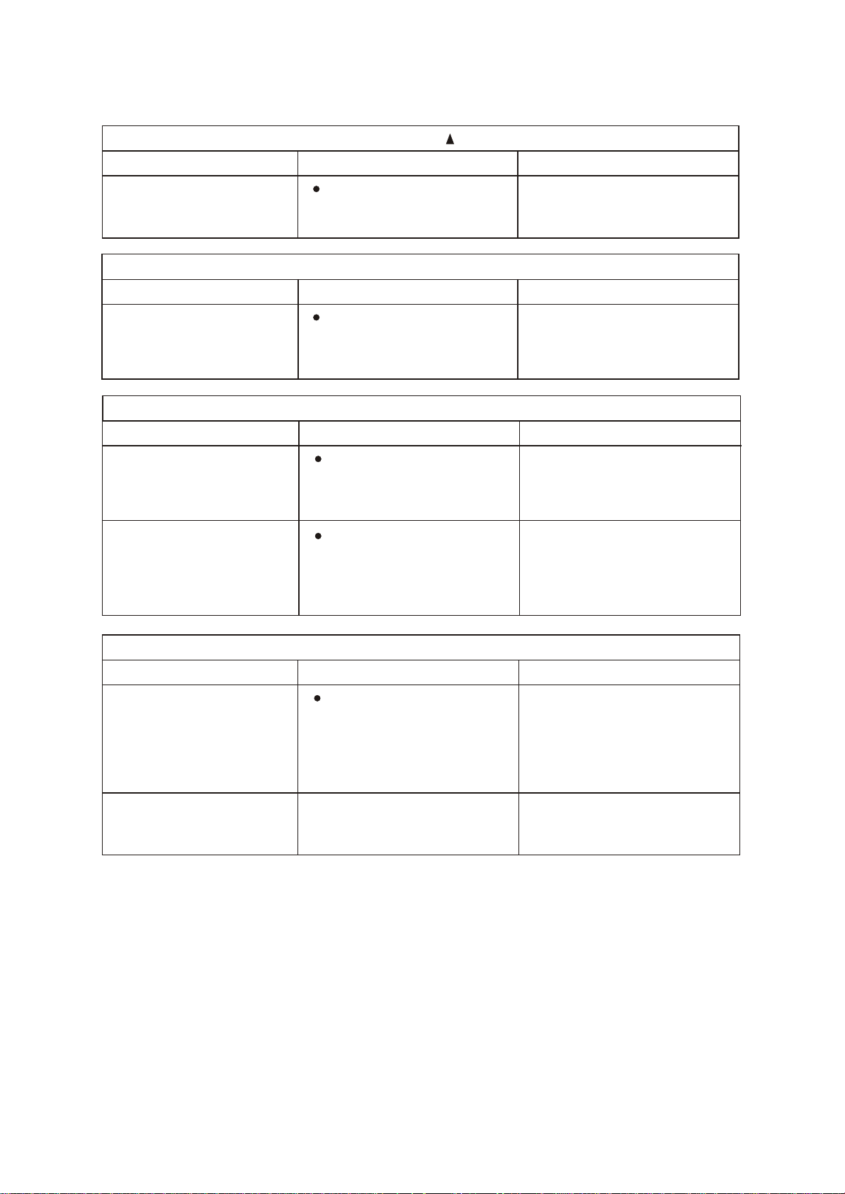
El Indicador de Transmisión "▲ " Nunca Aparece
Sintomas Revisar Razón o causa
La señal del control remoto
no es transmitida aún
cuando el botón ON/OFF es
presionado
• Controle si las pilas del
control remoto están
agotadas
La señal desde el control remoto
no es transmitida por falta de
energía.
El Display Nunca Enciende
Sintomas Revisar Razón o causa
El indicador TEMP. no
enciende.
• Verifique si el Modo indicado
en el display es "FAN
ONLY".
FAN ONLY
La temperatura no puede ser
seleccionada durante el modo
Ventilador Solo (Fan Only).
El Display se Apaga
Sintomas Revisar Razón o causa
La indicación en el display
desaparece luego de un
tiempo.
• Controle si la operación por
temporizador ha llegado a su
fin cuando se muestra OFF
TIMER en el display.
El funcionamiento del
acondicionador de aire se
detiene ya que transcurrió el
tiempo fijado.
El indicador ON TIMER se
apaga luego de un cierto
tiempo.
• Verifique si el
funcionamiento temporizado
(timer) comenzó cuando ON
TIMER es indicado en el
display.
Cuando llega al tiempo fijado
para el arranque temporizado, el
equipo arrancará
automáticamente y el indicador
correspondiente se apagará.
El Tono de Recepción de Señal No Suena
Sintomas Revisar Razón o causa
No se oye ningún sonido de
tono en la unidad interior,
aún cuando el botón ON/OFF
es presionado.
• Verifique si la señal que
transmite el control remoto
es direccionada
correctamente hacia el
receptor ubicado en el panel
de control de la unidad
interior, cuando es
presionado el botón
ON/OFF.
Dirija la señal transmitida por el
control remoto hacia el receptor
de la unidad interior, y entonces
presione repetidamente el botón
ON/ OFF dos veces.
Los botones del control
remoto no funcionan.
Presione el botón Reset.
18