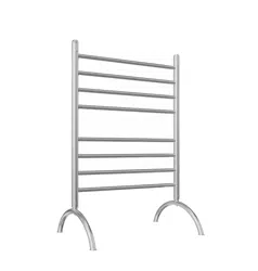
3-In-1 Towel Warmer
Installation and Operations Manual
MA5
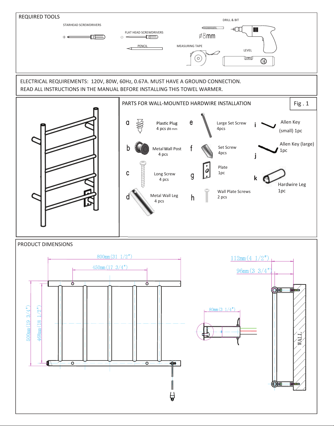
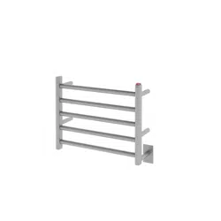
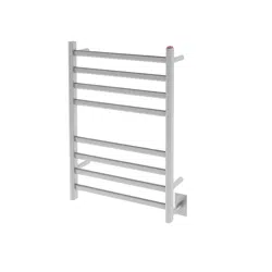
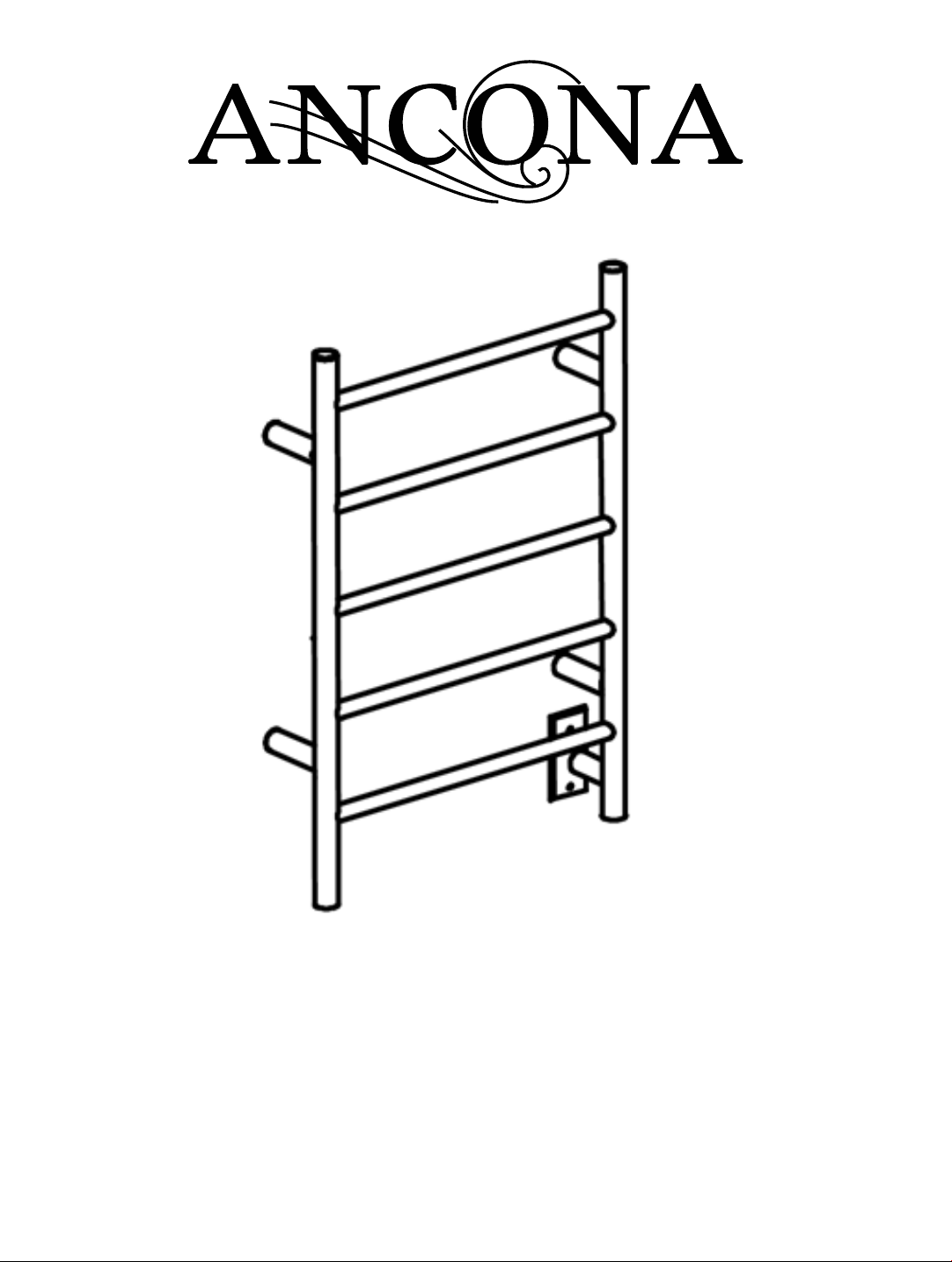
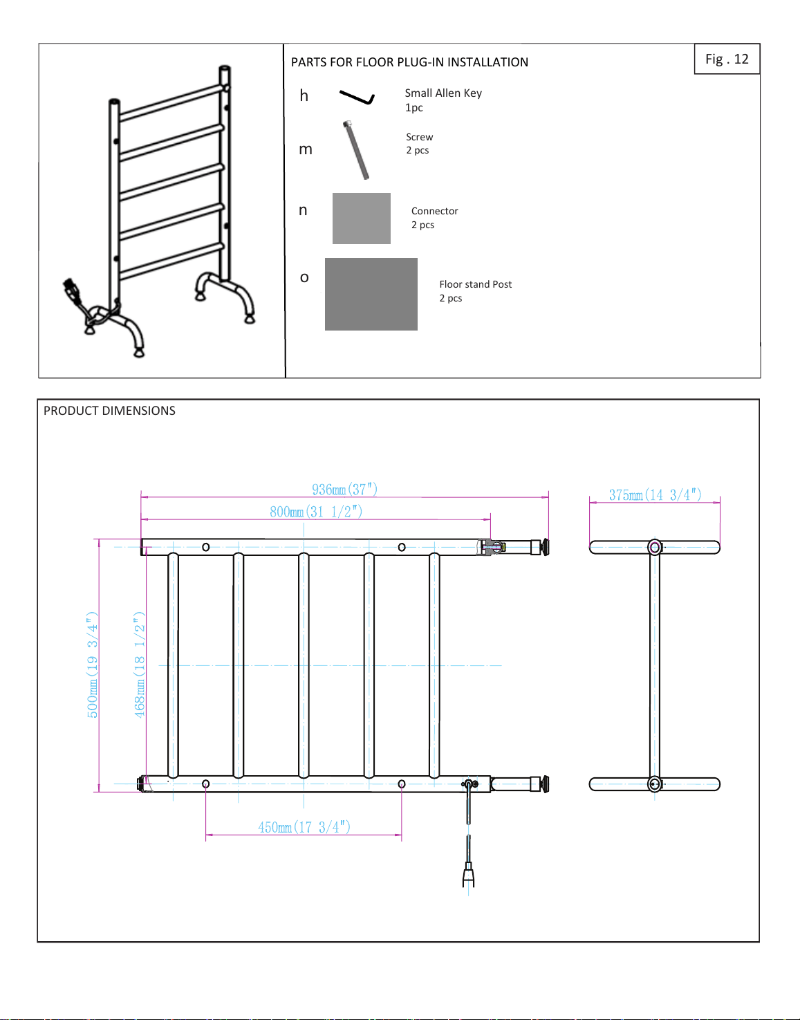
PRODUCT DIMENSIONS
FLAT HEAD SCREWDRIVERS
STARHEAD SCREWDRIVERS
PENCIL
DRILL & BIT
LEVEL
MEASURING TAPE
Long Screw
4 pcs
4 pcs
REQUIRED TOOLS
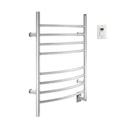
PARTS FOR WALL-MOUNTED HARDWIRE INSTALLATION
4 pcs Ø8 mm
all Post
4 pcs
ELECTRICAL REQUIREMENTS: 120V, 80W, 60Hz, 0.67A. MUST HAVE A GROUND CONNECTION.
Allen Key (large)
1pc
Allen Key
(small) 1pc
Large Set Screw
4pcs
Metal
Metal Wall Leg
Set Screw
4pcs
Plate
1pc
i
Wall Plate Screws
2 pcs
j
k
Hardwire Leg
1pc
READ ALL INSTRUCTIONS IN THE MANUAL BEFORE INSTALLING THIS TOWEL WARMER.
Fig . 1
HARDWIRE INSTALLATION
Step 1: Verifying installation parts (Fig. 1)
- )1.giF eeS( .remraw lewot ruoy htiw deilppus erew noitallatsni gnitnuom rof strap lla erusnE
- If any are missing, please contact us.
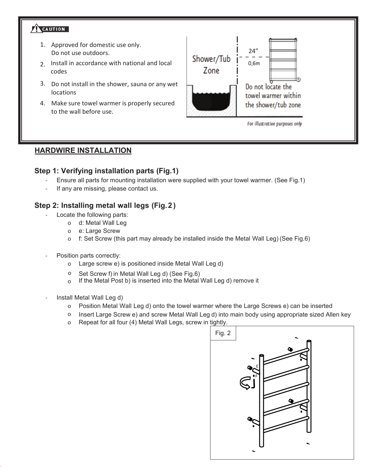
) 2 .giF( sgel llaw latem gnillatsnI :2 petS
- Locate the following parts:
o geL ll laW lateM :d
o
e: Large Screw
o
f: Set Screw (this part may already be installed inside the Metal Wall Leg) ( See Fig.6)
- Position parts correctly:
o
) is positioned inside Metal Wall L eg d)
o
Set Screw f) in Metal Wall L
eg d) (See Fig.6)
If the Metal Post b) is inserted into the Metal Wall Leg d) remove it
- Install Metal Wall Leg d)
o
Position Metal Wall Leg d) onto the towel warmer where the Large Screws e) can be inserted
o
Insert Large Screw e) an
d screw Metal Wall Leg d) into main body using appropriate sized Allen key
o
Repeat for all four (4) Metal Wall Legs
1.
Approved for domestic use only.
Do not use outdoors.
2.
Do not install in the shower, sauna or any wet
loctions
3.
24”
o
Fig. 2
.
Make sure towel warmer is properly secured
to the wall before use.
Install in accordance with nonal and local
codes
HARDWIRE INSTALLATION (cont.)
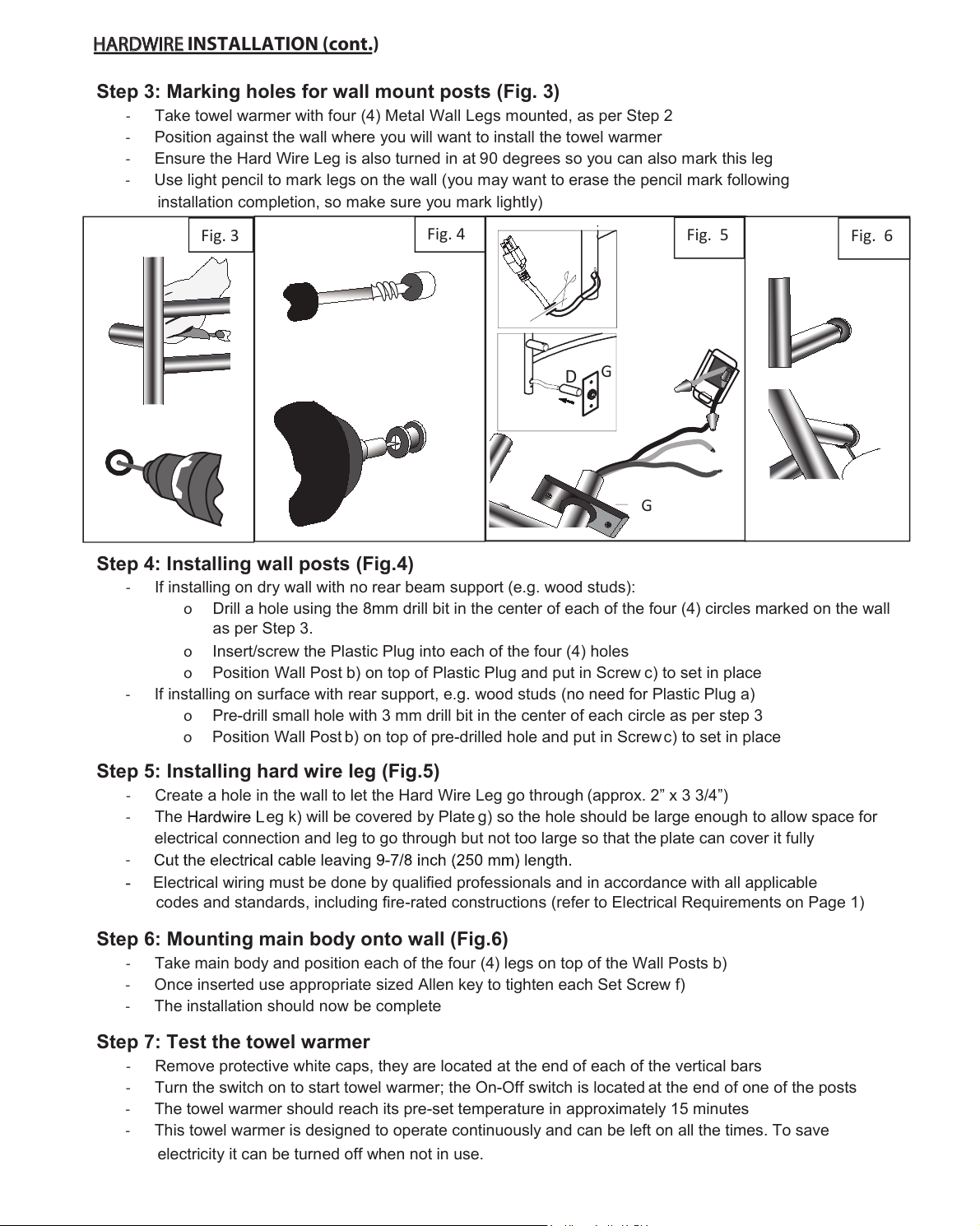
Step 3: Marking holes for wall mount posts (Fig. 3)
- Take towel warmer with four (4) Metal Wall Legs mounted, as per Step 2
- Position against the wall where you will want to install the towel warmer
- Ensure the Hard Wire Leg is also turned in at 90 degrees so you can also mark this leg
- Use light pencil to mark legs on the wall (you may want to erase the pencil mark following
installation completion, so make sure you mark lightly)
Step 4: Installing wall posts (Fig. 4)
- If installing on dry wall with no rear beam support (e.g. wood studs):
o
Drill a hole in the center of each of the four (4) circles marked on the wall
as per S tep 3
o Insert/screw the Plastic Plug into each of the four (4) holes
o Position Wall Post b) on top of Plastic Plug and put in Screw c) to set in place
- If installing on surface with rear support, e.g. wood studs (no need for Plastic Plug a)
o Pre-drill small hole in the center of each circle as per step 3
o Position Wall Post b) on top of pre-drilled hole and put in Screw c) to set in place
Step 5: Installing hard wire leg (Fig. 5)
- Create a hole in the wall to let the Hard Wire Leg go through (approx. 2” x 3 3/4”)
- The
eg will be covered by Plate ) so the hole should be large enough to allow space for
electrical connection and leg to go through but not too large so that the plate can cover it fully
-
Electrical wiring must be done by qualied professionals and in accordance with all applicable
codes and standards, including re-rated constructions (refer to Electrical Requirements on Page 1)
Step 6: Mounting main body onto wall (Fig. 6)
- Take main body and position each
of the four (4) legs on top of the Wall Posts b)
- Once inserted use appropriate sized Allen key to tighten e ach Set Screw f
- The installation should now be com plete
Step 7: Test the towel warmer
- Remove protective white caps, they are located at the end of each of the vertical bars
- Turn the switch on to start towel warmer; the On-Off switch is located at the end of one of the posts
- The towel warmer should reach its pre-set temperature in approximately 15 minutes
- This towel warmer is designed to operate continuously and can be left on all the times. To save
electricity it can be turned off when not in use.
Fig. 4
Fig. 6
Fig. 3
Fig. 5
D

PRODUCT DIMENSIONS
Screw
4 pcs
Metal Wall Leg
4 pcs
Set Screw
4pcs
Fig .
Small Allen Key
1pc
Large Allen Key
1pc
PARTS FOR AD INSTALLATION
4 pcs Ø8 mm
Wall Post
4 pcs
Large Screw
4 pcs
WA I INSTALLATION
Step 1: Verifying installation parts (Fig. )
- Ensure all parts for mounting installation were supplied with your towel warmer. (See Fig.7 )
- If any are missing, please contact us.
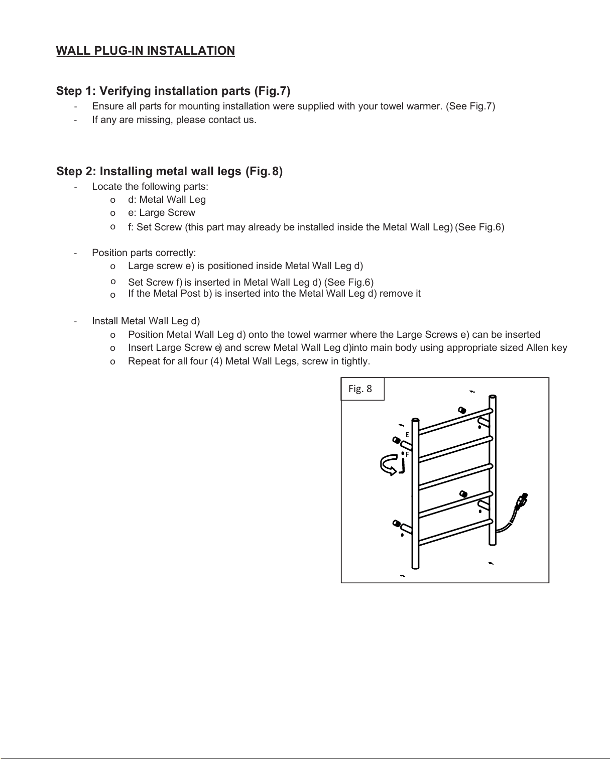
Step 2: Installing metal wall legs (F ig
- Locate the following parts:
o geL ll laW lateM :d
o
e: Large Screw
o
f: Set Screw (this part may already be installed inside the Metal Wall Leg) ( See Fig.6)
- Position parts correctly:
o
Large screw e) is positioned inside Metal Wall L eg d)
o
Set Screw f) is inserted in Metal Wall L
eg d) (See Fig.6)
If the Metal Post b) is inserted into the Metal Wall Leg d) remove it
- Install Metal Wall Leg d)
o
Position Metal Wall Leg d) onto the towel warmer where the Large Screws e) can be inserted
o Insert Large Screw e) and screw Metal Wall Leg
d)into main body
using appropriate sized Allen key
o
Repeat for all four (4) Metal Wall Legs
Fig
.
o
-Take towel warmer with 4 wall leg mounted, as per Step 2.
-Position against the wall where you will want to install the towel warmer.
-Use light pencil to mark legs on the wall (you may want to erase the pencil mark following installation
completion, so make sure you mark lightly).
I
-If installing on dry wall with no rear beam support (e.g. wood studs):
o
f f f
o Insert/screw the Plastic Plug in each of the four (4) holes
o Position wall post b) on top of plastic plug and put in screw c) to set in place
-If installing on surface with rear support, e.g. wood studs (no need for Plastic Plug a)
o
f
o Position Wall Post b) on top of pre-drilled hole and put in Screw c) to set in place
-Take main body and position each of the four (4) legs on top of the Wall Post b)
-Once inserted use appropriate sized Allen key to tighten each Set Screw f)
-The installation should be complete
-Remove protective white caps, they are located at the end of each of the vertical bars.
-Turn the switch on to start towel warmer; the On-Off switch is located at the end of one of the posts.
-The towel warmer should reach its pre-set temperature in approximately 15 minutes.
-This towel warmer is designed to operate continuously and can be left on all the times. To save electricity it
can be turned off when not in use.
Fig. 9 Fig. 10 Fig. 11
WA I INSTALLATION
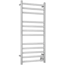
PRODUCT DIMENSIONS
Screw
pcs
Fig .
Small Allen Key
1pc
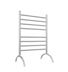
PARTS FOR INSTALLATION
loor stnd ost
pcs
onnector
pcs
h
m
n
o
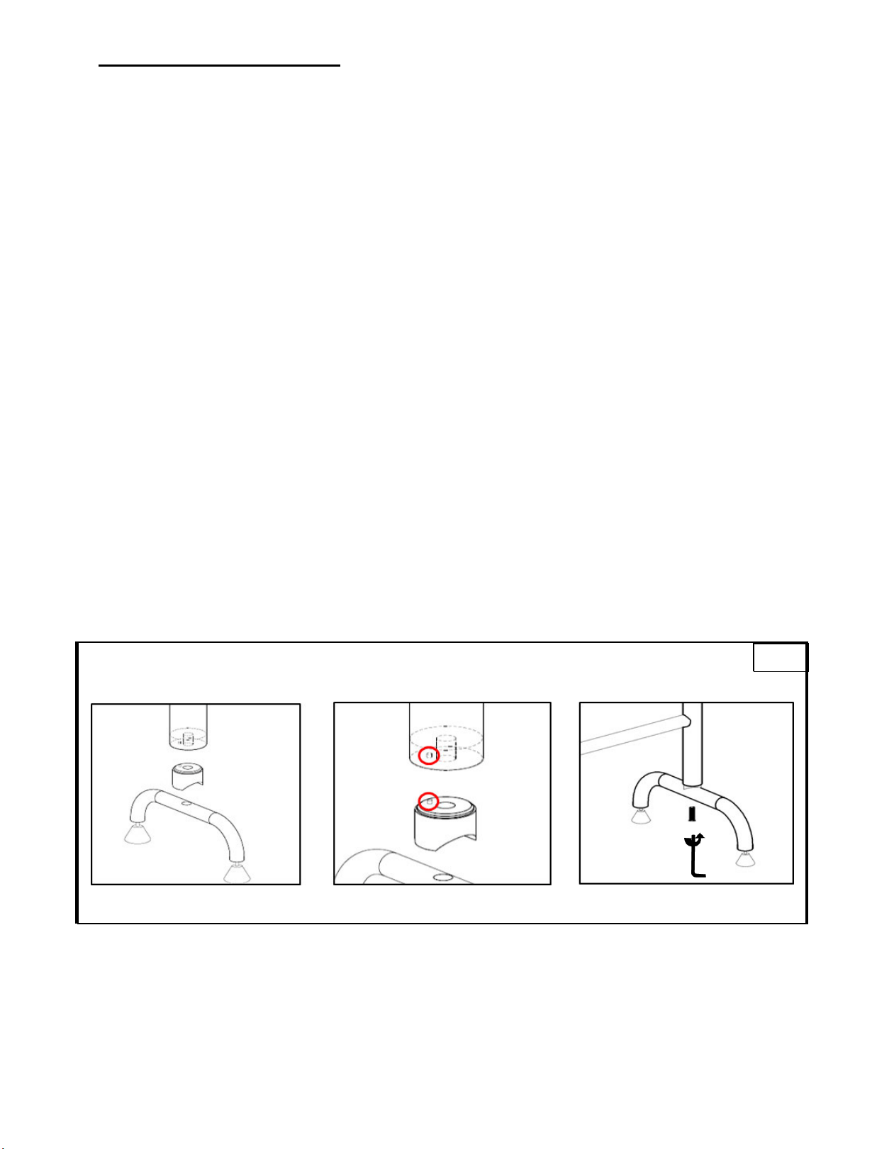
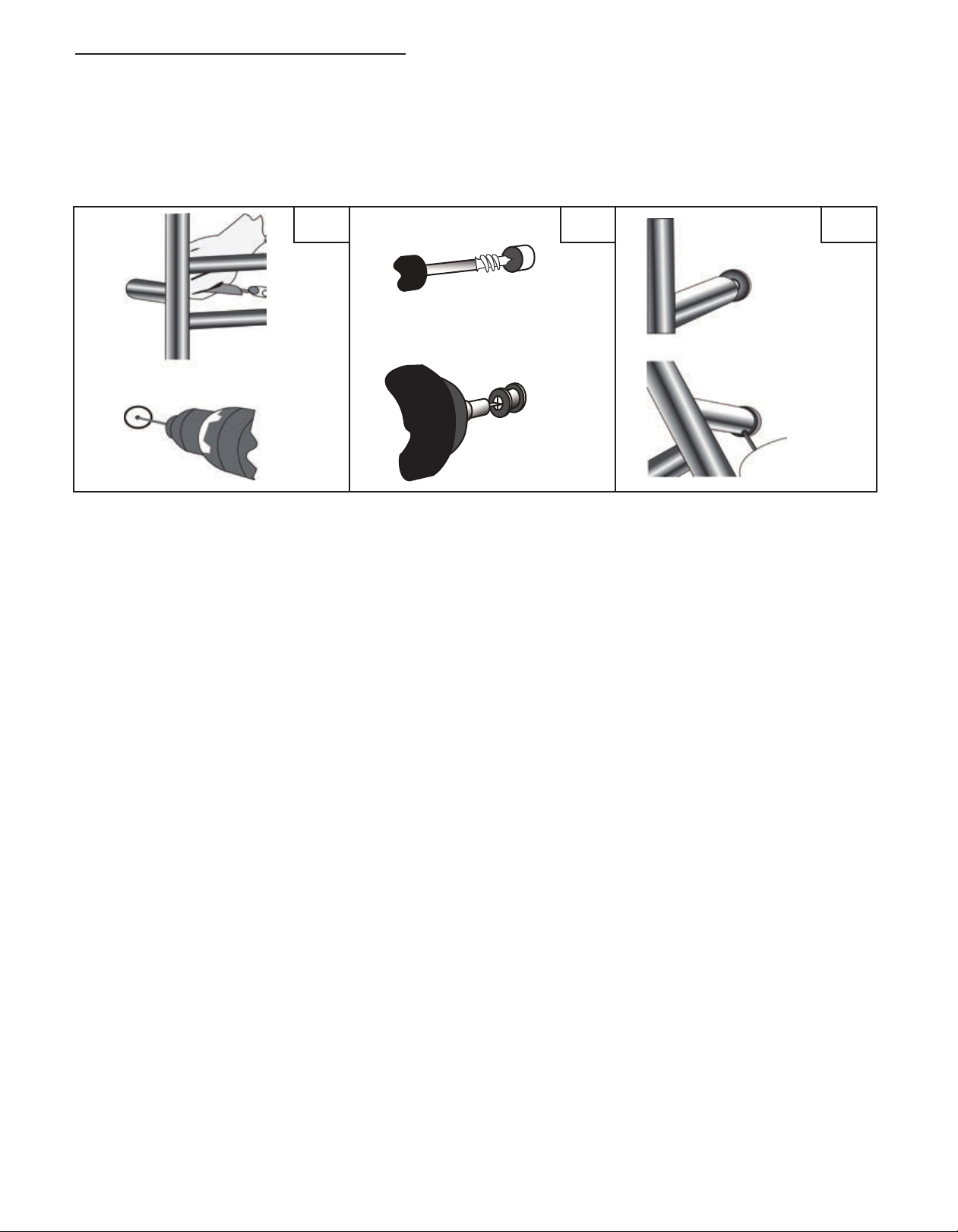
R I IAAI
I
Fig.
-Remove protective white caps, they are located at the end of each of the vertical bars.
-Turn the switch on to start towel warmer; the On-Off switch is located at the end of one of the posts.
-The towel warmer should reach its pre-set temperature in approximately 15 minutes.
-This towel warmer is designed to operate continuously and can be left on all the times. To save electricity it
can be turned off when not in use.
N
O
M
Operation and Maintenance Instructions
• After installation, connect the electric power and turn on the switch. The indicator light will show red and
the towel warmer will start to work.
• Turn off the switch when the towel warmer is not in use. The indicator light will turn dark and the towel
warmer will stop working.
• Clean the towel warmer with a soft dry towel. Do not clean with abrasive cleaning powder.
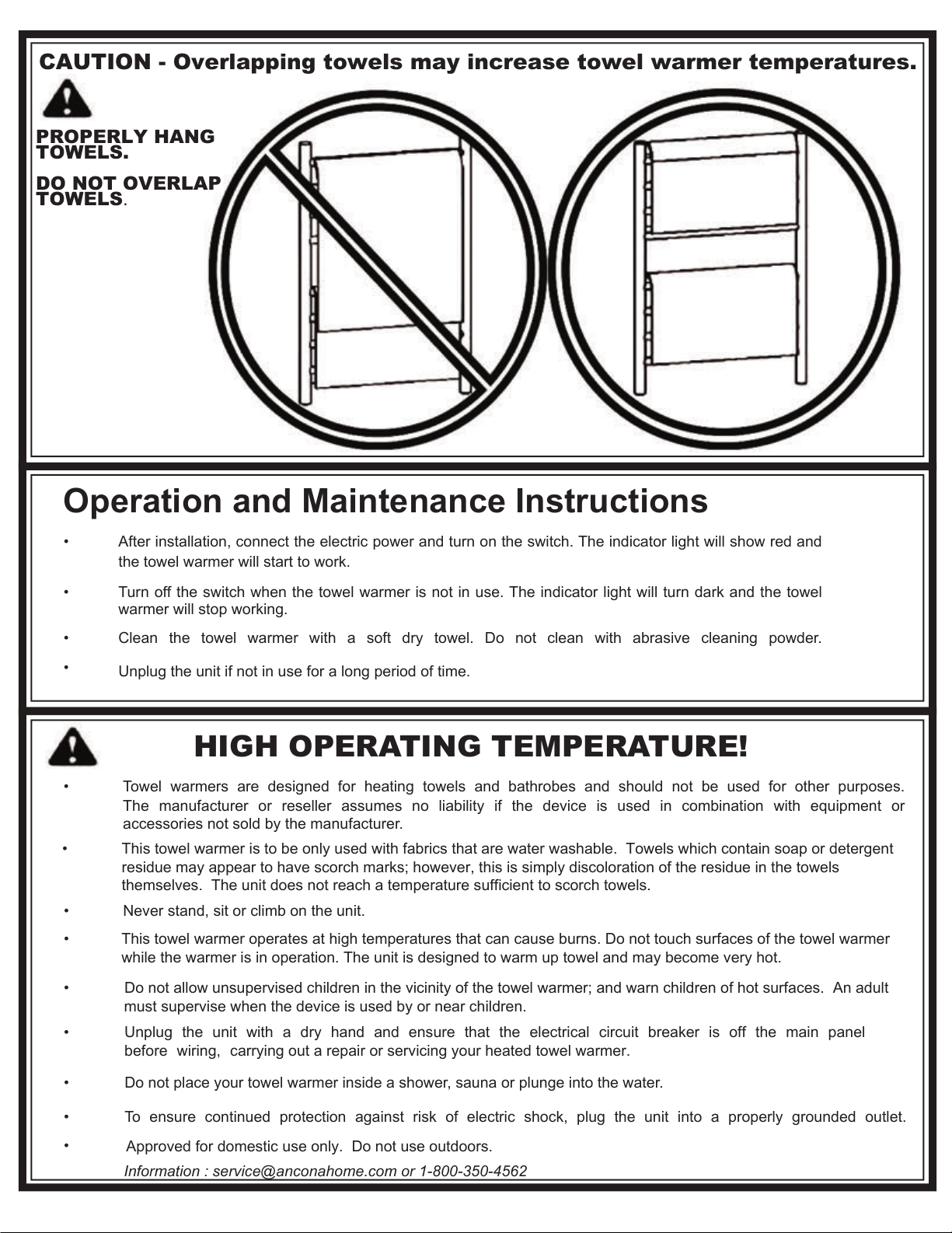
PROPERLY HANG
TOWELS.
DO NOT OVERLAP
TOWELS.
CAUTION - Overlapping towels may increase towel warmer temperatures.
• Towel warmers are designed for heating towels and bathrobes and should not be used for other purposes.
The manufacturer or reseller assumes no liability if the device is used in combination with equipment or
accessories not sold by the manufacturer.
• Never stand, sit or climb on the unit.
•
This towel warmer operates at high temperatures that can cause burns. Do not touch surfaces of the towel warmer
while the warmer is in operation. The unit is designed to warm up towel and may become very hot.
• Do not allow unsupervised children in the vicinity of the towel warmer; and warn children of hot surfaces. An adult
must supervise when the device is used by or near children.
•
Unplug the unit and ensure that the electrical circuit breaker is off the main panel
before wiring, carrying out a repair or servicing your heated towel warmer.
• Do not place your towel warmer inside a shower, sauna or plunge into the water.
• To ensure continued protection against risk of electric shock, plug the unit into a properly grounded outlet.
•
Approved for domestic use only. Do not use outdoors.
HIGH OPERATING TEMPERATURE!
•
•
.
Information : @anconaho.com or 1-800-350-4562
3-en-1
Guide d’installation et de fonctionnement
MA5

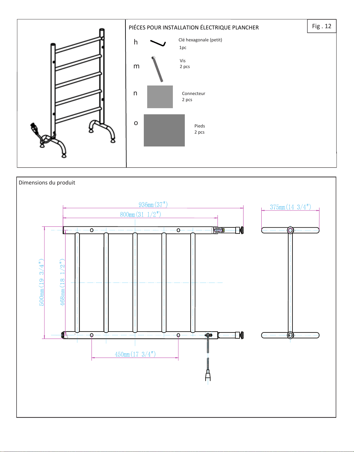
Dimensions du produit
TOURNEVIS PLATTOURNEVIS ÉTOILE
CRAYON
PERÇEUSE ET MÈCHE
NIVEAURUBAN À MESURER
Fig . 1
Vis
4 pcs
1pc
Clé hexagonale (gros)
1pc
Tampon à vix
4 pcs
Pieu en métal
4 pcs
4 pcs
pcs
Éxigences électriques: 120V, W, 60Hz, .A. rnce lunit dns une prise dutement relie l terre.
Vis de réglage
4pcs
Plaque
1pc
i
Vis
2 pcs
k
P AA AD
j
oteu
rccordement
1pc
ire toutes les instructions dns l section nstlltion de ce mnuel AA dinstller le cuffeserviettes.
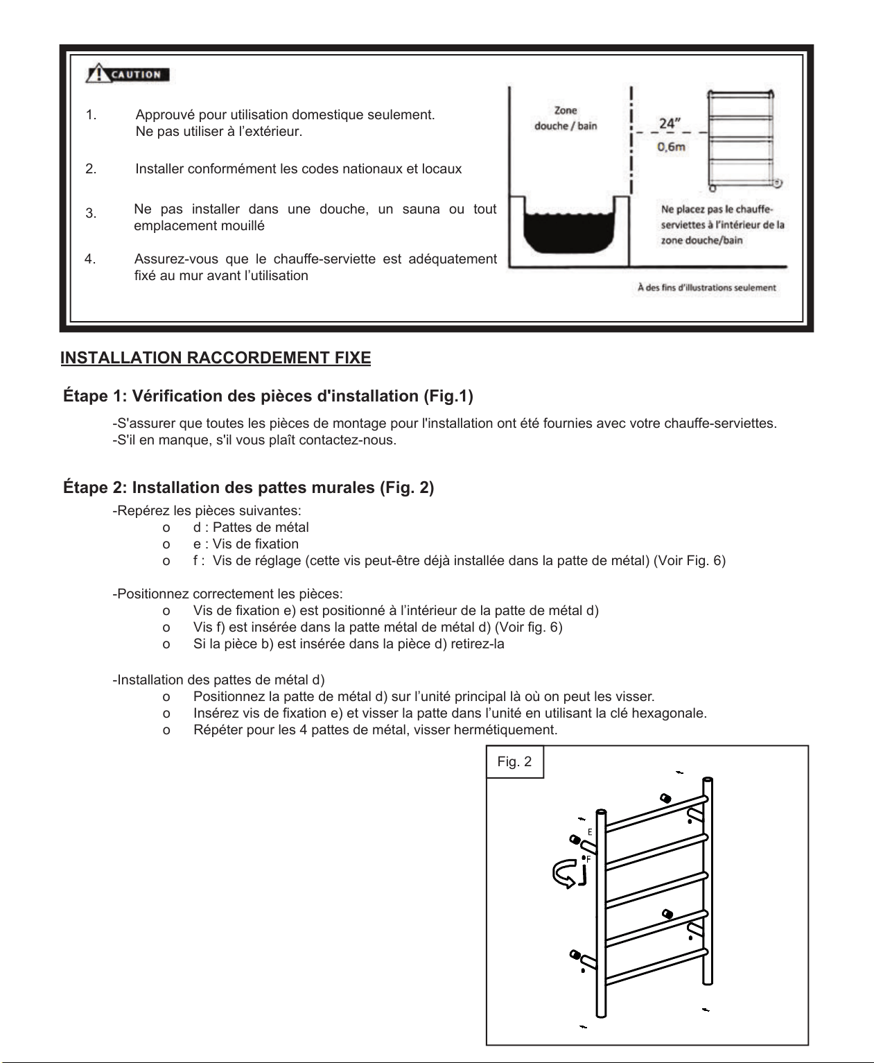
1.
2.
Ne pas installer dans une douche, un sauna ou tout
emplacement mouillé
3.
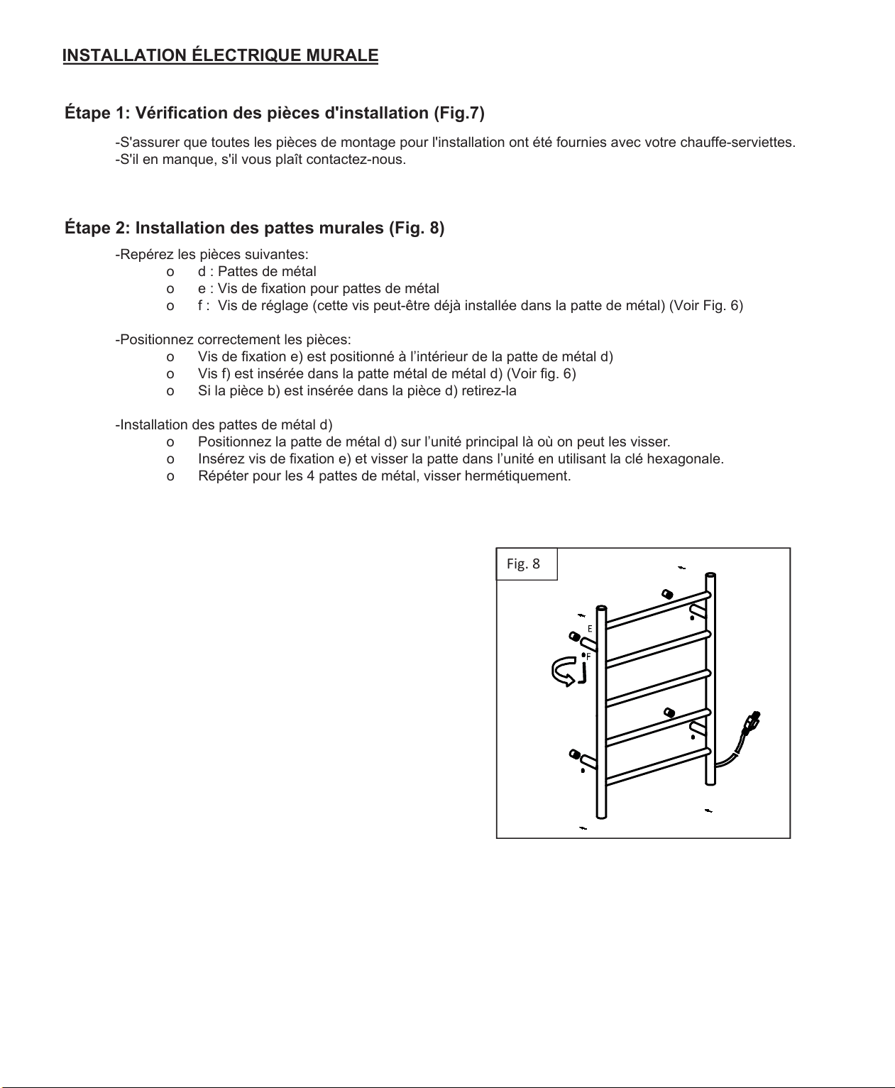
-S'assurer que toutes les pièces de montage pour l'installation ont été fournies avec votre chauffe-serviettes.
-S'il en manque, s'il vous plaît contactez-nous.
I
-Repérez les pièces suivantes:
o
d : Pattes de métal
o
e : Vis de fixation
o
f :
-Positionnez correctement les pièces:
o
f ) est positionné à l’intérieur de la patte de métal d)
o
Vis f) est insérée dans la patte métal de métal d) (Voir fig. 6)
o Si la pièce b) est insérée dans la pièce d) retirez-la
-Installation des pattes de métal d)
o Positionnez la patte de métal d) sur l’unité principal là où on peut les visser.
o Insérez vis de fixation e) et visser la patte dans l’unité en utilisant la clé hexagonale.
o
Répéter pour les 4 pattes de métal .
INSTALLATION RARDEE IE
Fig. 2
.
Assurez-vous que le chauffe-serviette est adéquatement
fixé au mur avant l’utilisation
Installer conformément les codes nationaux et locaux
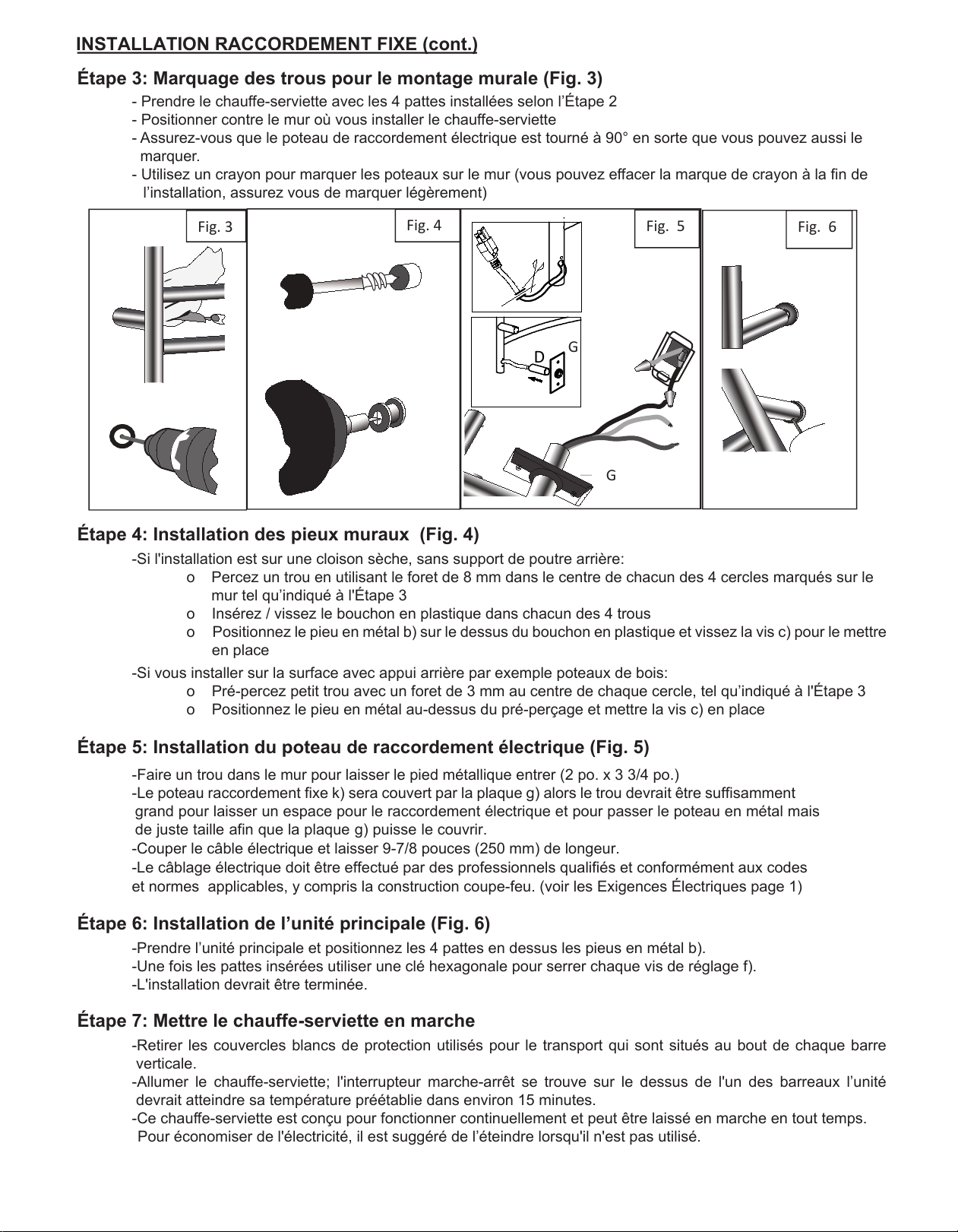
- Prendre le chauffe-serviette avec les 4 pattes installées selon l’Étape 2
- Positionner contre le mur où vous installer le chauffe-serviette
- Assurez-vous que le poteau de raccordement électrique est tourné à 90° en sorte que vous pouvez aussi le
marquer.
- Utilisez un crayon pour marquer les poteaux sur le mur (vous pouvez effacer la marque de crayon à la fin de
l’installation, assurez vous de marquer légèrement)
I
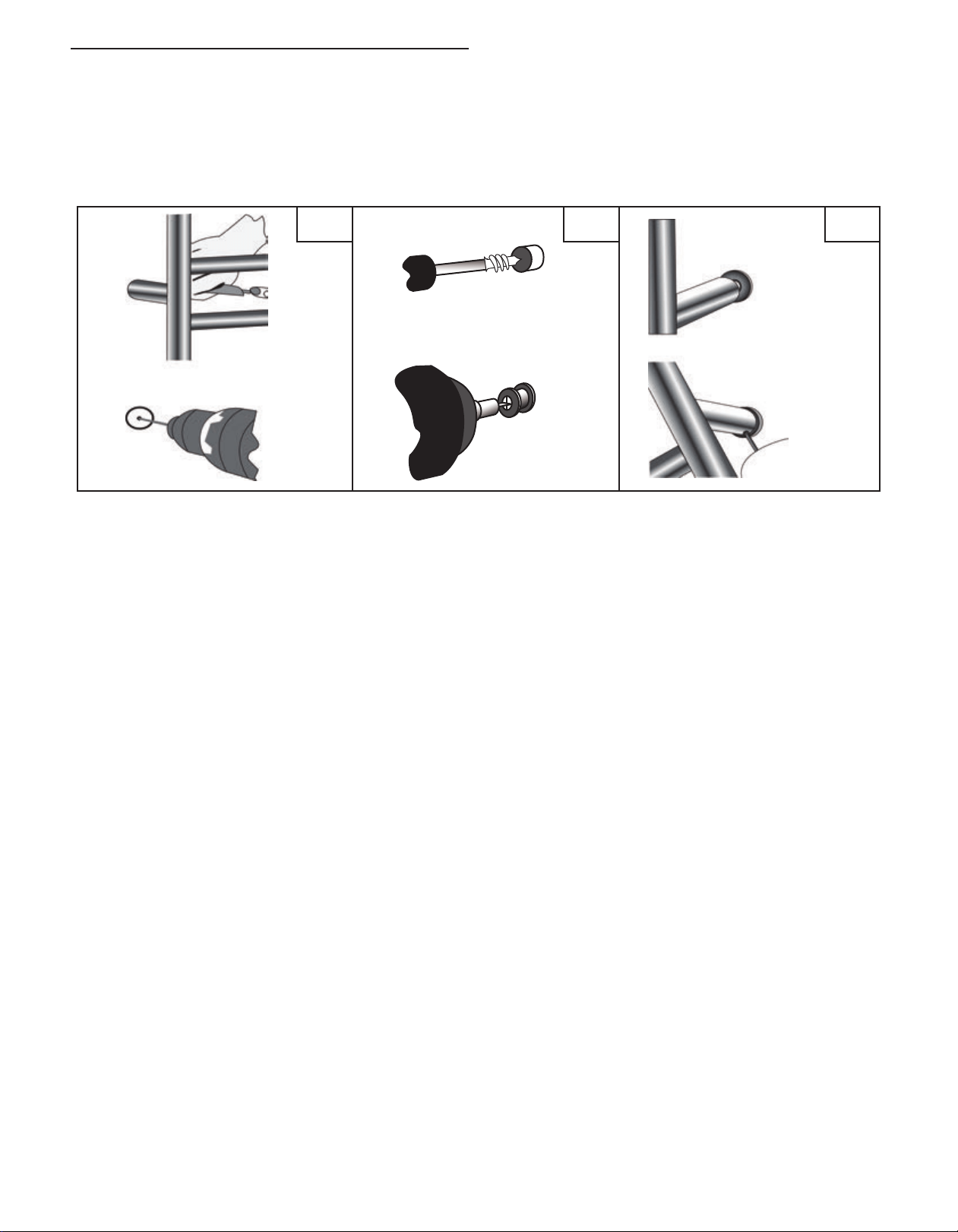
-Si l'installation est sur une cloison sèche, sans support de poutre arrière:
o
Percez un trou f dans le centre de chacun des 4 cercles marqués sur le
mur tel qu’indiqué à l'Étape 3
o Insérez / vissez le bouchon en plastique dans chacun des 4 trous
o Positionnez le pieu en métal b) sur le dessus du bouchon en plastique et vissez la vis c) pour le mettre
en place
-Si vous installer sur la surface avec appui arrière par exemple poteaux de bois:
o
Pré-percez petit trou f au centre de chaque cercle, tel qu’indiqué à l'Étape 3
o Positionnez le pieu en métal au-dessus du pré-perçage et mettre la vis c) en place
I
-Faire un trou dans le mur pour laisser le pied métallique entrer (2 po. x 3 3/4 po.)
-Le poteau sera couvert par la plaque ) alors le trou devrait être suffisamment
le raccordement électrique et pour passer le poteau en métal mais
de juste taille afin que la plaque ) puisse le
97/ 0
-Le câblage électrique doit être effectué par des professionnels qualifiés et conformément aux codes
et normes applicables, y compris la construction coupe-feu. (voir les Exigences Électriques page 1)
I
-Prendre l’unité principale et positionnez les 4 pattes en dessus les pieus en métal b).
-Une fois les pattes insérées utiliser une clé hexagonale pour serrer chaque vis de réglage f).
-L'installation devrait être terminée.
Étape 7: Mettre le chauffe-serviette en marche
-Retirer les couvercles blancs de protection utilisés pour le transport qui sont situés au bout de chaque barre
verticale.
-Allumer le chauffe-serviette; l'interrupteur marche-arrêt se trouve sur le dessus de l'un des barreaux l’unité
devrait atteindre sa température préétablie dans environ 15 minutes.
-Ce chauffe-serviette est conçu pour fonctionner continuellement et peut être laissé en marche en tout temps.
Pour économiser de l'électricité, il est suggéré de l’éteindre lorsqu'il n'est pas utilisé.
INSTALLATION RARDEE IE
Fig. 4
Fig. 6 Fig. 3
Fig. 5
D
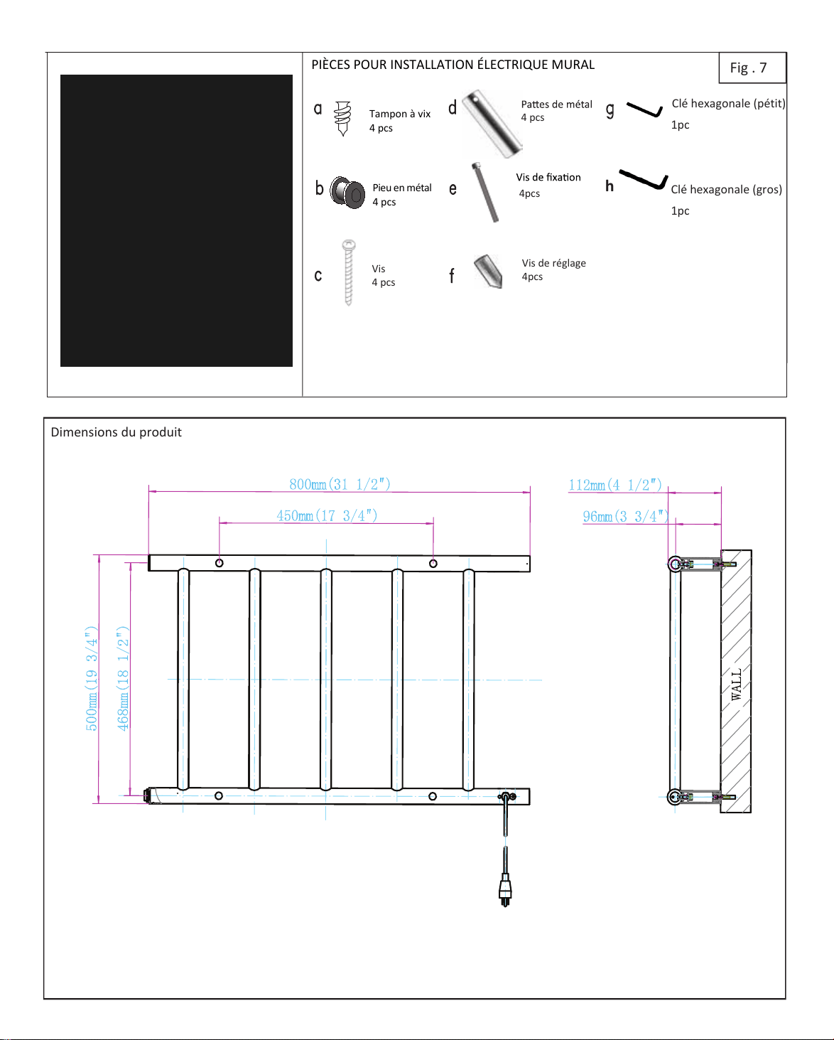
Fig .
Vis
4 pcs
Vis de réglage
4pcs
Pieu en métal
4 pcs
4 pcs
P AA A
l eonle ptit
1pc
Clé hexagonale (gros)
1pc
Dimensions du produit
4pcs
4 pcs
-S'assurer que toutes les pièces de montage pour l'installation ont été fournies avec votre chauffe-serviettes.
-S'il en manque, s'il vous plaît contactez-nous.
I
-Repérez les pièces suivantes:
o
d : Pattes de métal
o
e : Vis de fixation pour pattes de métal
o
f :
-Positionnez correctement les pièces:
o
f ) est positionné à l’intérieur de la patte de métal d)
o
Vis f) est insérée dans la patte métal de métal d) (Voir fig. 6)
o Si la pièce b) est insérée dans la pièce d) retirez-la
-Installation des pattes de métal d)
o Positionnez la patte de métal d) sur l’unité principal là où on peut les visser.
o Insérez vis de fixation e) et visser la patte dans l’unité en utilisant la clé hexagonale.
o
Répéter pour les 4 pattes de métal .
INSTALLATION ERIE RAE
Fig
.
- Prendre le chauffe-serviette avec les 4 pattes installées selon l’étape 2
- Positionner contre le mur où vous installer le chauffe-serviette
- Utilisez un crayon pour marquer les poteaux sur le mur (vous pouvez effacer la marque de crayon à la fin de
l’installation, assurez vous de marquer légèrement)
I
-Si l'installation est sur une cloison sèche, sans support de poutre arrière:
o
f
o Insérez / vissez le bouchon en plastique dans chacun des 4 trous
o Positionnez le pieu en métal b) sur le dessus du bouchon en plastique et vissez la vis c) pour le mettre
en place
-Si vous installer sur la surface avec appui arrière par exemple poteaux de bois:
o
Pré-percez petit trou f au centre de chaque cercle, tel qu’indiqué à l'étape 3
o Positionnez le pieu métallique au-dessus du pré-perçage et mettre la vis c) en place
I
-Prendre l’unité principale et positionnez les 4 pattes au dessus des pièces murales b)
-Une fois les pattes insérées utiliser une clé hexagonale pour serrer chaque vis de réglage f)
-L'installation devrait être terminée
-Retirer les couvercles blancs de protection utilisés pour le transport qui sont situés au bout de chaque barre
verticale
-Allumer le chauffe-serviette; l'interrupteur marche-arrêt se trouve sur le dessus de l'un des barreaux l’unité
devrait atteindre sa température préétablie dans environ 15 minutes
-Ce chauffe-serviettes est conçu pour fonctionner continuellement et peut être laissé en marche en tout temps.
Pour économiser de l'électricité, il est suggéré de l’éteindre lorsqu'il n'est pas utilisé
Fig. 9 Fig. 10 Fig. 11
INSTALLATION ERIE RAE
is
pcs
Fig .
l eonle petit
pc
INSTALLATION A
ieds
pcs
onnecteur
pcs
Dimensions du produit
h
m
n
o
I
1
-Retirer les couvercles blancs de protection utilisés pour le transport qui sont situés au bout de chaque barre
verticale
-Allumer le chauffe-serviette; l'interrupteur marche-arrêt se trouve sur le dessus de l'un des barreaux l’unité
devrait atteindre sa température préétablie dans environ 15 minutes
-Ce chauffe-serviettes est conçu pour fonctionner continuellement et peut être laissé en marche en tout temps.
Pour économiser de l'électricité, il est suggéré de l’éteindre lorsqu'il n'est pas utilisé
INSTALLATION ERIE AHER
Fig.
N
O
M
Instructions de fonctionnement et d’entretien
•
L
• L
•
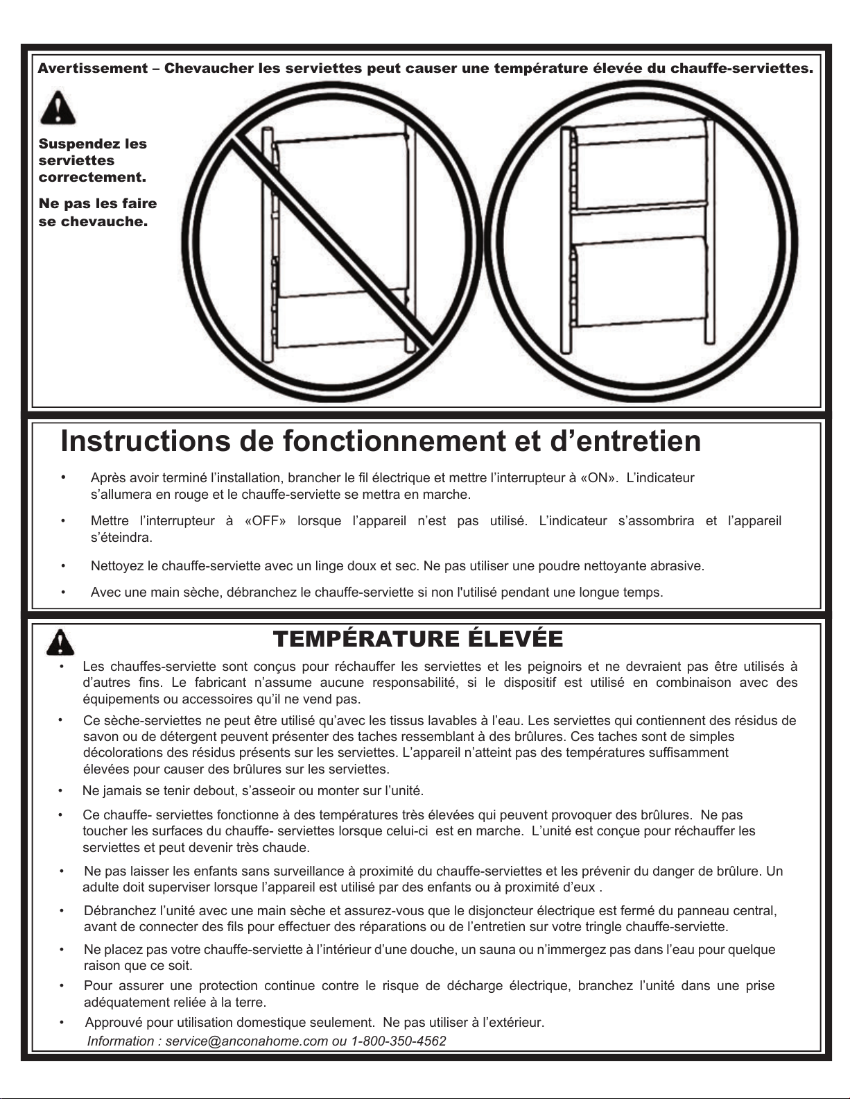
Suspendez les
serviettes
correctement.
Ne pas les faire
se chevauche.
•
•
•
ff f
f ff ff
•
•
•
•
•
r
Avertissement – Chevaucher les serviettes peut causer une température élevée du chauffe-serviettes.
TEMPÉRATURE ÉLEVÉE
•
•
Information : @anconacom ou 1-800-350-4562