Loading ...
Loading ...
Loading ...
re and (;leaning
Stainless Steel ( ooktop
Sealed
b'LI rTle) _"
assemblies
Slits
Usea sewingneedle,twist-tie
and/ortoothbrushto unclogthe
small holesand slits in theburner
headsandburnerrings.
Toaid reassemhiy,eachbrass
BurnerHeadismarkedwith a
clockface. ReplacetheBurner
Headwith thearrow pointing
to the rear ofthe coektop
(12o'clockposition).
Turn all controls OFF befi)re removing the
burner parts.
The burner grates, burner caps and burner
ring sub-assemblies can be lifted ott, making
them easy to clean.
CAUTION: DO NOT OPERATE THE
BURNER WITHOUT ALL BURNER PARTS
IN PLACE.
MISE EN CAUSE : N'UTILISEZ PAS DE
BRIJLEUR QUI N'A PAS TOUTES SES
PI]_]CES EN PLACE.
For proper ignition, make sure the small holes in
the burner _ings are kept open. A sewing needle
or wire twist-tie works well to unclog them.
The slits in the burner heads of your cooktop
must be kept clean at all limes for an even,
mlhampered flame.
You should clean the suriace burner routinely,
espedally alter bad spillovers, which could clog
these openings.
To I'eIl/OVe b/li'ned-on too(l_ soak the b/lI'neI"
heads and rings in a solution of mild liquid
detergent and hot water fin" 20-30 minutes.
For more stubborn stains, use a toothbHBh.
Clean the burner bases in place on the
cooktop.
To remove the burner parts:
1 I,ift ott the burner cap and burner head.
2 Remove the burner ring locking nut using
a 1H_;" socket wrench, crescent wrench or
channel-lock pliers.
3 i,ifl off the burner ring. Do not remove the
burner bases.
Before putting the burner parts back, shake out
excess water and then dry them thoroughly by
setting them in a warm oven fin" 30 minutes.
To replace the burner parts:
Make sure all parts fin" the burner are
firmly seated.
1 Align the locator pins on the burner ring
into the labeled hole in the burner base.
Seat in place.
2 Replace the burner ring locking ntlt and
hand-tighten. Using the wrench or pliers,
ttlrn the ntlt 1/4 ttlrn to secure it in place.
3 Align the locator pin in the burner head into
the hole in the burner ring. Seat in place.
4 Replace the burner caps.
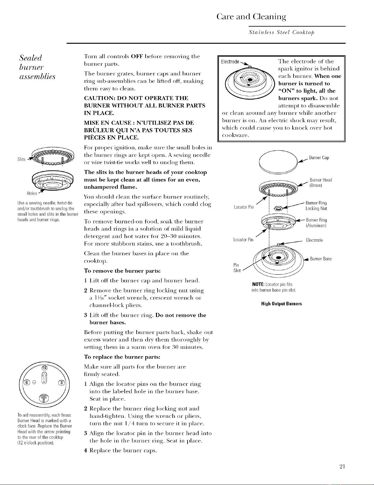
Electrode_ The electrode of the
spark ignitor is behind
each burne_: When one
burner is turned to
"ON" to light, all the
burners spark. Do not
attempt to disassemble
or clean around any burner while another
burner is on. An electric shock mav result,
which could Catlse vou to knock over hot
cookware.
LocatorPin
LocatorPin
._i BurnerCap
BurnerHead
_ (Brass)
I
_ BurnerRing
LockingNut
@ urner Ring
(Aluminum)
/
Electrode
Pin
. Burner Base
NOTE:Locaterpinfits
into burnerbasepinslot.
High Output Burners
21
Loading ...
Loading ...
Loading ...