Hisense
lUJ~~
~~IQ>
D~~ir~~
1nl@~
D~~ir~lUJ~D@~~
Thank
you
very
much
for
purchasing this
Air
Conditioner.
Please read this use and
installation
instructions
carefully
before installing and using this
appliance
and keep this
manual
for
future
reference.
Contents,
Safety instructions ·
Preparation before use
Safety Precautions
Installation
instructions
1
3
4
13
Installation diagram
·········································································································
13
Identification
of
parts
·······························································································
14
Indoor unit
14
Outdoor
unit·····························································································································
14
Display
introduction
··································································································
15
Remote controller
··········································································································
16
Operation instructions
Operation modes
·········································································································
18
Airflow direction control
SMART mode
SUPER mode
19
20
22
QUIET mode
.....................................................................................................................
22
TIMER mode
23
ECONOMY mode
··········································································································
23
IFEEL mode
.....................................................................................................................
24
DIMMER button
··················
······································24
CLOCK button
··················································································································
24
SLEEP mode
.......................................................................................................................
25
8°C HEAT mode
················································································································
25
Select the installation locations
26
Indoor unit installation
··························································································································
27
Connecting of the cable
29
Wiring diagram
30
Outdoor unit installation
··························································································································
31
Air purging
..........................................................................................................................................................
32
Maintenance
·················································································································································
33
Protection
..
34
Troubleshooting
35
Safety instructions
I
•
1.
To
guarantee the unit work normally, please
read
the manual carefully before
installation,
and
try to install strictly according to this manual.
•
2.
Do
not let air enter the refrigeration system
or
discharge refrigerant when moving the
air conditioner.
•
3.
Properly ground the air conditioner into the earth.
•
4.
Check the connecting cables and pipes carefully, make sure they are correct and firm
before connecting the power
of
the air conditioner.
•
5.
There must
be
an
air-break switch.
• 6.
After
installing, the consumer
must
operate the
air
conditioner correctly
according to this manual, keep a suitable storage
for
maintenance and moving
of
the
air
conditioner in the future.
•
7.
Fuse of indoor unit: T 3.15A 250VAC or T 5A 250VAC. Please refer
to
the screen
printing
on
the circuit board for the actual parameters, which must
be
consistent with the
parameters
on
the screen printing.
•
8.
For 2.5,3.5KWmodels, fuse
of
outdoor unit:T 15A 250VAC
or
T 20A
250VAC.
Please
refer to the screen printing
on
the circuit board for the actual parameters, which must be
consistent with the parameters
on
the screen printing.
•
9.
For 5.0KWmodels, fuse
of
outdoor unit: T 20A
250VAC.
•
10.
For
7.1
KWmodels, fuse of outdoor unit: T 30A
250VAC.
• 11. The installation instructions
for
appliances that are intended to be permanently
connected to fixed wiring, and have a leakage current that may exceed 10 mA,
shall state that the installation
of
a residual current device (RCD) having a rated
residual operating current not exceeding 30 mA is advisable.
• 12. Warning: Risk
of
electric
shock
can cause
injury
or
death: Disconnect all
remote electric power supplies before servicing.
• 13. The maximum length
of
the connecting pipe between the indoor unit and
outdoor
unit
should be less than 5 meters.
It
will affect the efficiency
of
the
air
conditioner
if
the distance longer than
that
length.
• 14. This appliance is
not
intended
for
use
by
person (including children) with
reduced physical, sensory
or
mental capabilities,
or
lack
of
experience and
knowledge, unless they have been given supervision
or
instruction concerning
use
of
the
appliance by a person responsible
for
their
safety.Children should be
supervised to ensure
that
they do not play with the appliance.Cleaning and user
maintenance shall not be made by children without supervision.
• 15. This appliance can be used by children aged from 8 years and above and
persons with reduced physical, sensory
or
mental capabilities
or
lack
of
experience and knowledge
if
they
have been given supervision
or
instruction
concerning use
of
the appliance in a safe way and understand the hazards
involved. Children shall
not
play
with the appliance. Cleaning and user
maintenance shall not be made by children without supervision.
-1-
Safety instructions I
• 16. The batteries in remote controller must be recycled
or
disposed
of
properly.
Disposal
of
Scrap Batteries --- Please discard the batteries as sorted municipal
waste
at
the accessible collection point.
• 17.
If
the appliance is fixed wiring, the appliance must be fitted with means
for
disconnection from the supply mains having a contact separation in all poles that
provide full disconnection under
over
voltage category
111
conditions, and these
means must be incorporated in the fixed wiring in accordance with the wiring rules.
• 18.
If
the supply cord is damaged, it must be replaced by the manufacturer, its
service agent
or
similarly qualified persons
in
order
to avoid a hazard.
• 19. The appliance shall be installed
in
accordance with national wiring regulations.
• 20. Servicing shall only be performed as recommended by the equipment
manufacturer. Maintenance and repair requiring the assistance
of
other
skilled
personnel shall
be
carried
out
under the supervision
of
the person competent in
the use
offlammable
refrigerants.
• 21. The appliance shall
not
be installed
in
the laundry.
• 22. Regarding to installation, please refer to section "Installation instructions".
• 23. Regarding to maintenance, please refer to section "Maintenance".
• 24. For models using R32 refrigerant, piping connection should be conducted on
outdoor side.
• 25.The AC is not allowed to install
in
the mining area and sand storm area.
-2-
Preparation before
use/
I Note
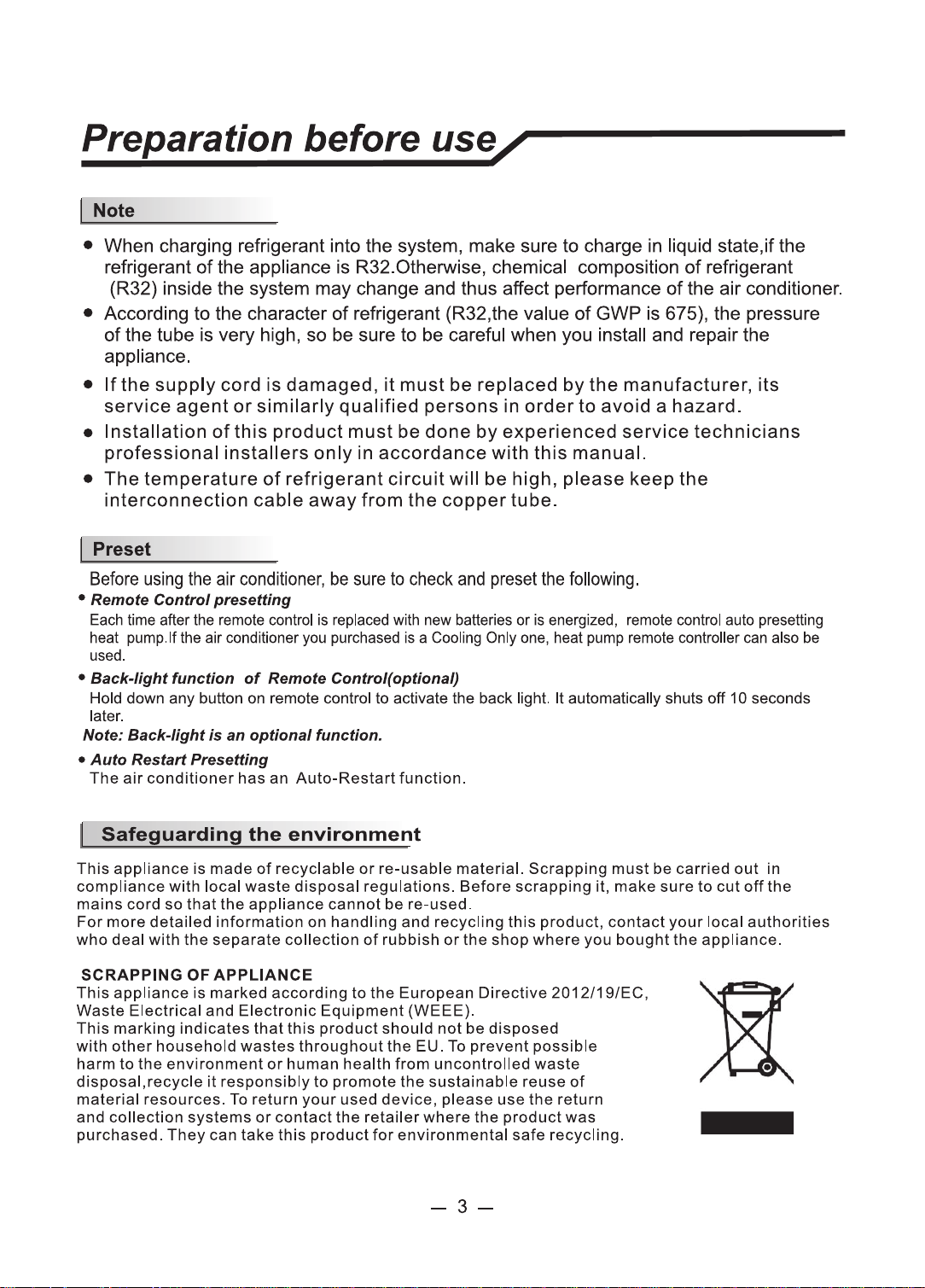
• When charging refrigerant into the system, make sure to charge in liquid state,if the
refrigerant
of
the appliance is R32.0therwise, chemical composition
of
refrigerant
(R32) inside the system may change and thus affect performance
of
the air conditioner.
• According to the character
of
refrigerant (R32,the value
of
GWP is 675), the pressure
of
the tube is very high, so be sure to
be
careful when you install and repair the
appliance.
•
If
the
supply
cord
is
damaged,
it
must
be
replaced
by
the
manufacturer,
its
service
agent
or
similarly
qualified
persons
in
order
to
avoid
a
hazard.
•
Installation
of
this
product
must
be
done
by
experienced
service
technicians
professional
installers
only
in
accordance
with
this
manual.
•
The
temperature
of
refrigerant
circuit
will
be
high,
please
keep
the
interconnection
cable
away
from
the
copper
tube.
Preset
Before
using
the
air
conditioner,
be
sure
to
check
and
preset
the
following.
•
Remote
Control
presetting
Each
time after the
remote
control is
replaced
with new batteries or is energized,
remote
control auto presetting
heat pump.If
the
air conditioner
you
purchased
is a
Cooling
Only
one,
heat
pump
remote
controller
can
also
be
used.
•
Back-light
function
of
Remote
Control(optionaQ
Hold down any button
on
remote control to activate the back light. It automatically shuts
off
10 seconds
later.
Note:
Back-light
is
an
optional
function.
•
Auto
Restart Presetting
The
air
conditioner
has
an
Auto-Restart
function.
I
Safeguarding
the
environment
This
appliance
is
made
of
recyclable
or
re
-
usable
material.
Scrapping
must
be
carried
out
in
compliance
with
local
waste
disposal
regulations.
Before
scrapping
it,
make
sure
to
cut
off
the
mains
cord
so
that
the
appliance
cannot
be
re-used
.
For
more
detailed
information
on
handling
and
recycling
this
product,
contact
your
local
authorities
who
deal
with
the
separate
collection
of
rubbish
or
the
shop
where
you
bought
the
appliance.
SCRAPPING
OF
APPLIANCE
This
appliance
is
marked
according
to
the
European
Directive
2012/19/EC,
Waste
Electrical
and
Electronic
Equipment
(WEEE).
This
marking
indicates
that
this
product
should
not
be
disposed
with
other
household
wastes
throughout
the
EU.
To
prevent
possible
harm
to
the
environment
or
human
health
from
uncontrolled
waste
disposal,recycle
it
responsibly
to
promote
the
sustainable
reuse
of
material
resources.
To return
your
used
device,
please
use
the
return
and
collection
systems
or
contact
the
retailer
where
the
product
was
purchased.
They
can
take
this product
for
environmental
safe
recycling.
-3-
-
Safety precautions /
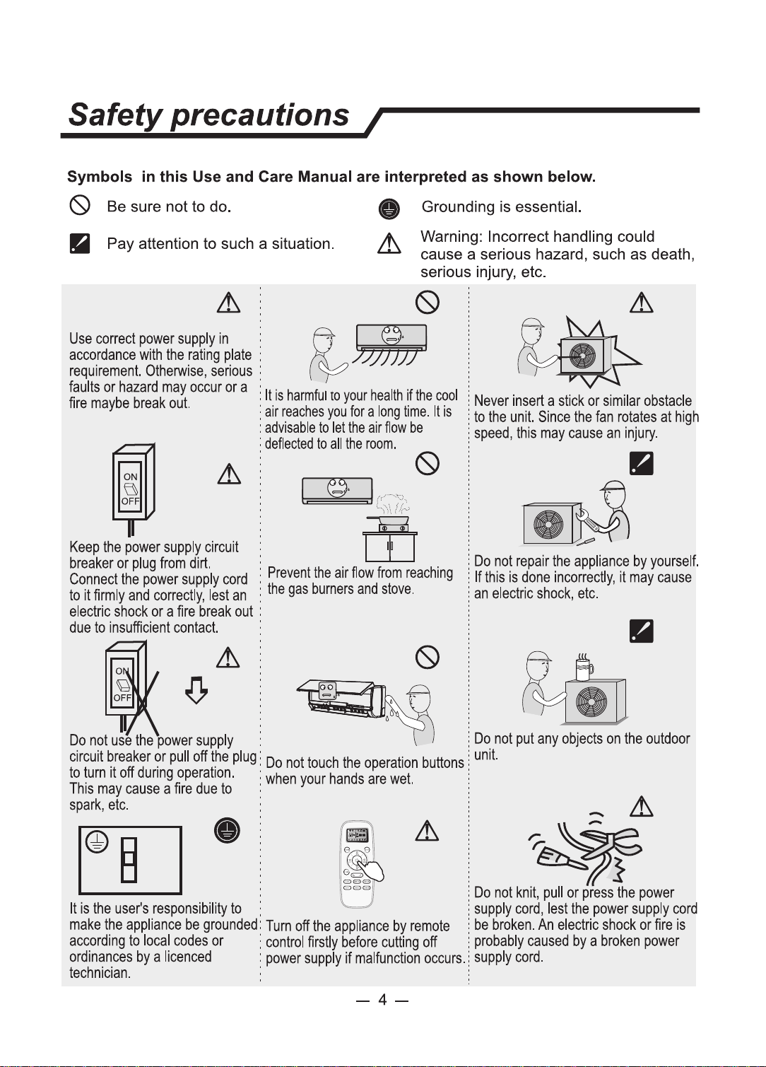
Symbols
in
this Use and Care Manual are interpreted as shown below.
(9
Be sure not to do. Grounding
is
essential.
II
Pay attention to such a situation.
Warning: Incorrect handling could
cause a serious hazard, such
as
death,
serious injury, etc.
~
Use
correct
power
supply
in
i
~
accordance
with
the
rating
plate
:
~
requirement.
Otherwise,
serious
:
faults
or
hazard
may
occur
or
a I
It
is
harmful
10
your
health
if
the
cool
fire
maybe
break
out.
:
air
reaclles
you
for
a
long
time.
It
is
:
advisable
to
let
the
air
flow
be
:
deflected
to
all
the
room.
~
@
lr,-~\;J,
',1\
{Irv
Keep
the
power
supply
circuit
m
breaker
or
plug
from
dirt.
: . .
Connect
the
power
supply
cord
:
Prevent
the
air
flow
from
reaching
to
it
firmly
and
correctly,
lest
an
:
the
gas
burners
and
stove.
electric
shock
or
a
fire
break
out
:
due
to
insufficient
contact.
:
Do
not
use
the
ower
supply
.
circuit
~reaker
~r
pull
off
t_he
plug
:
Do
not
touch
the
operation
buttons
to
!Urn
1t
off
dunng
operation.
:
when
your
hands
are
wet.
This
may
cause
a
fire
due
to
:
spark,
etc.
:
Never
insert
a
stick
or
similar
obstacle
to
the
unit.
Since
the
fan
rotates
at
high
speed,
this
may
cause
an
injury.
~
--
·
;,,,
Do
not
repair
the
appliance
by
yourself.
If
this
is
done
incorrectly,
it
may
cause
an
electric
shock,
etc.
Do
not
put
any
objects
on
the
outdoor
unit.
-
~
~
Do
not
knit,
pull
or
press
the
power
It
is
the
user's
responsibility
to
.
supply
cord,
lest
the
power
supply
cord
make
the
appliance
be
grounded:
Turn
off
the
appliance
by
remote
be
broken.
An
electric
shock
or
fire
is
according
to
local
codes
or
:
control
firstly
before
cutting
off
probably
caused
by
a
broken
power
ordinances
by
a
licenced
:
power
supply
if
malfunction
occurs.
supply
cord.
technician.
-4-
Safety precautions /
Precautions
for
using
R32 refrigerant
For
the
multi
system,
the
refrigerant
refer
to
the
multi
outdoor
unit.
The
basic
installation
work
procedures
are
the
same
as
the
conventional
refrigerant
(R22
or
R410A).
However,
pay
attention
to
the
following
points:
~
CAUTION
1.
Transport
of
equipment
containing
flammable
refrigerants
Compliance with the transport regulations
2.
Marking
of
equipment
using
signs
Compliance with local regulations
3.
Disposal
of
equipment
using
flammable
refrigerants
Compliance with national regulations
4.
Storage
of
equipment/appliances
The storage
of
equipment should be in accordance with the manufacturer's
instructions.
5.
Storage
of
packed
(unsold)
equipment
• Storage package protection should be constructed such that mechanical
damage to the equipment inside the package will not cause a leak
of
the
refrigerant charge.
• The maximum number
of
pieces
of
equipment permitted to be stored together
will be determined by local regulations.
6.
Information
on
servicing
6-1
Checks
to
the
area
Prior to beginning work
on
systems containing flammable refrigerants, safety
checks are necessary to ensure that the risk
of
ignition is minimised. For repair
to the refrigerating system, the following precautions shall be complied with
prior
to conducting
work
on
the system.
6-2
Work
procedure
Work shall be undertaken under a controlled procedure so as to minimise the
risk
of
flammable gas
or
vapour being present while the work is being
performed.
6-3
General
work
area
• All maintenance
staff
and others working in the local area shall be instructed
on
the nature
of
work being carried out. Work in confined spaces shall be
avoided.
• The area around the workspace shall be sectioned off. Ensure that the
conditions within the area have been made safe by control
offlammable
material.
6-4
Checking
for
presence
of
refrigerant
• The area shall be checked with an appropriate refrigerant detector
prior
to and
during work, to ensure the technician is aware
of
potentially flammable
atmospheres.
• Ensure that the leak detection equipment being used is suitable
for
use with
flammable refrigerants, i.e. non-sparking, adequately sealed or intrinsically
safe.
-5-
Safety precautions /
~
CAUTION
6-5
Presence
of
fire
extinguisher
•
If
any
hot
work is
to
be conducted on the refrigeration equipment
or
any
associated parts, appropriate fire extinguishing equipment shall be available
to hand.
• Have a
dry
powder
or
C02
fire extinguisher adjacent to the charging area.
6-6 No
ignition
sources
• No person carrying out work in relation
to
a refrigeration system which involves
exposing
any
pipe work
that
contains
or
has contained flammable refrigerant
shall use any sources
of
ignition in such a manner
that
it may lead
to
the risk
of
fire
or
explosion.
• All possible ignition sources, including cigarette smoking, should be kept
sufficiently far away from the site
of
installation, repairing, removing and
disposal, during which flammable refrigerant can possibly be released
to
the
surrounding space.
• Prior
to
work taking place, the area around the equipment is
to
be surveyed to
make sure that there are no flammable hazards
or
ignition risks. "No Smoking"
signs shall be displayed.
6-7
Ventilated area
• Ensure
that
the area is in the open or
that
it is adequately ventilated before
breaking into the system
or
conducting
any
hot work.
• A degree
of
ventilation shall continue during the period
that
the
work
is carried
out.
• The ventilation should
safely
disperse any released refrigerant and preferably
expel
it
externally into the atmosphere.
6-8
Checks
to
the
refrigeration
equipment
• Where electrical components are being changed,
they
shall be
fit
for the
purpose and
to
the correct specification.
•
At
all times the manufacturer's maintenance and service guidelines shall be
followed.
If
in
doubt consult the manufacturer's technical department
for
assistance.
• The following checks shall be applied
to
installations using flammable
refrigerants:
-The
charge size is in accordance with the room size within which the
refrigerant containing parts are installed;
- The ventilation machinery and outlets are operating adequately and are not
obstructed;
-
If
an indirect refrigerating circuit is being used, the secondary circuit shall be
checked
for
the presence
of
refrigerant;
- Marking
to
the equipment continues
to
be visible and legible. Markings and
signs
that
are illegible shall be corrected;
- Refrigeration pipe or components are installed in a position where
they
are
unlikely to be exposed
to
any substance which may corrode refrigerant
containing components, unless the components are constructed
of
materials
-6-
Safety precautions /
~
CAUTION
which are inherently resistant to being corroded
or
are suitably protected
against being so corroded.
6-9
Checks
to
electrical devices
• Repair and maintenance to electrical components shall include initial safety
checks and component inspection procedures.
•
If
a
fault
exists that could compromise safety, then no electrical supply shall be
connected to the circuit until
it
is satisfactorily dealt with.
•
If
the
fault
cannot be corrected immediately but it is necessary
to
continue
operation, an adequate temporary solution shall
be
used.
• This shall be reported to the owner
of
the equipment so all parties are advised.
• Initial safety checks shall include:
- That capacitors are discharged: this shall be done in a safe manner
to
avoid
possibility
of
sparking;
- That there no live electrical components and wiring are exposed while
charging, recovering
or
purging the system;
- That there is continuity
of
earth bonding.
7. Repairs
to
sealed components
• During repairs to sealed components, all electrical supplies shall be
disconnected from the equipment being worked upon prior to
any
removal
of
sealed covers, etc.
•
If
it
is absolutely necessary to have an electrical supply
to
equipment during
servicing, then a permanently operating form
of
leak detection shall be located
at
the most critical point to warn
of
a potentially hazardous situation.
• Particular attention shall be paid
to
the following to ensure that by working on
electrical components, the casing is not altered in such a
way
that
the level
of
protection is affected.
• This shall include damage to cables, excessive number
of
connections,
terminals not made to original specification, damage
to
seals, incorrect fitting
of
glands, etc.
• Ensure
that
apparatus is mounted securely.
• Ensure
that
seals
or
sealing materials have not degraded such that
they
no
longer serve the purpose
of
preventing the ingress
of
flammable atmospheres.
• Replacement parts shall be in accordance with the manufacturer's
specifications.
NOTE:
The use
of
silicon sealant may inhibit the effectiveness
of
some types
of
leak detection equipment. Intrinsically safe components do not have to be
isolated prior
to
working on them.
8.
Repair to
intrinsically
safe
components
•
Do
not
apply
any
permanent inductive
or
capacitance loads
to
the circuit
without ensuring
that
this will not exceed the permissible voltage and current
permitted
for
the equipment
in
use.
• Intrinsically safe components are the only types that can be worked on while
-7-
Safety precautions /
Lt
CAUTION
live in the presence
of
a flammable atmosphere. The
test
apparatus shall be at
the correct rating.
• Replace components only with parts specified by the manufacturer.
• Other parts may result in the ignition
of
refrigerant in the atmosphere from a
leak.
9.
Cabling
• Check
that
cabling will not be subject to wear, corrosion, excessive pressure,
vibration, sharp edges or any other adverse environmental effects.
• The check shall also take into account the effects
of
aging
or
continual
vibration from sources such as compressors
or
fans.
1 a.Detection
of
flammable refrigerants
• Under
no
circumstances shall potential sources
of
ignition be used
in
the
searching
for
or detection
of
refrigerant leaks.
• A halide torch (or
any
other
detector
using a naked flame) shall
not
be used.
11. Leak detection methods
• The following
leak
detection methods are deemed acceptable
for
systems
containing flammable refrigerants:
- Electronic leak detectors shall be used
to
detect flammable refrigerants, but
the sensitivity may not be adequate, or may need re-calibration. (Detection
equipment shall be calibrated in a refrigerant-free area.)
- Ensure that the detector is not a potential source
of
ignition and is suitable
for
the refrigerant used.
- Leak detection equipment shall be set at a percentage
of
the LFL
of
the
refrigerant and shall be calibrated to the refrigerant employed and the
appropriate percentage
of
gas (25 % maximum) is confirmed.
- Leak detection fluids are suitable
for
use with most refrigerants but the use
of
detergents containing chlorine shall be avoided as the chlorine may react
with the refrigerant and corrode the copper pipe-work.
-
If
a
leak
is suspected, all naked flames shall be removed/ extinguished.
-
If
a leakage
of
refrigerant is found which requires brazing, all
of
the
refrigerant shall be recovered from the system,
or
isolated (by means
of
shut
off
valves) in a
part
of
the system remote from the leak.
- Oxygen free nitrogen (OFN) shall then be purged through the system both
before and during the brazing process.
12.Removal and evacuation
• When breaking into the refrigerant circuit to make
repairs-
or
for
any
other
purpose - conventional procedures shall be used.
• However,
it
is important that best practice is followed since flammability is a
consideration.
• The following procedure shall be adhered to:
- Remove refrigerant;
- Purge the circuit with inert gas;
-8-
Safety precautions /
Lt
CAUTION
c) Before attempting the procedure ensure that:
- Mechanical handling equipment is available,
if
required,
for
handling
refrigerant cylinders;
- All personal protective equipment is available and being used correctly;
- The recovery process is supervised
at
all times by a competent person;
- Recovery equipment and cylinders conform
to
the
appropriate standards.
d)
Pump down refrigerant system,
if
possible.
e)
If
a vacuum is
not
possible, make a manifold so
that
refrigerant can be
removed from various parts
of
the system.
f) Make sure that cylinder is situated on the scales before recovery takes
place.
g)
Start
the
recovery machine and operate in accordance with manufacturer's
instructions.
h) Do
not
overfill cylinders. (No more than 80 % volume liquid charge).
I)
Do not exceed the maximum working pressure
of
the cylinder, even
temporarily.
j)
When
the
cylinders have been filled correctly and the process completed,
make sure that the cylinders and the
equipment
are removed from site
promptly and all isolation valves on
the
equipment are closed off.
k) Recovered refrigerant shall
not
be charged into another refrigeration system
unless
it
has been cleaned and checked.
15.Labelling
• Equipment shall
be
labelled stating that it has been de-commissioned and emptied
of
refrigerant.
• The label shall be dated and signed.
• Ensure that there are labels
on
the equipment stating the equipment contains
flammable refrigerant.
16.Recovery
• When removing refrigerant from a system,
either
for
servicing
or
decommissioning, it is recommended good practice
that
all refrigerants are
removed safely.
• When transferring refrigerant into cylinders, ensure
that
only
appropriate
refrigerant recovery cylinders are employed.
• Ensure
that
the
correct
number
of
cylinders
for
holding the total system charge
is available.
• All cylinders
to
be used are designated
for
the recovered refrigerant and
labelled
for
that refrigerant (i.e. special cylinders for the recovery
of
refrigerant).
• Cylinders shall be complete with pressure relief valve and associated shut-
off
valves in good working order.
• Empty recovery cylinders are evacuated and,
if
possible, cooled before
recovery occurs.
• The recovery equipment shall be in good working
order
with a
set
of
-10-

Safety precautions /
it
CAUTION
instructions concerning the equipment
that
is at hand and shall be suitable for
the recovery
of
flammable refrigerants.
• In addition, a
set
of
calibrated weighing scales shall be available and in good
working order.
• Hoses shall be complete with leak-free disconnect couplings and
in
good
condition.
• Before using the recovery machine, check
that
it
is in
satisfactory
working
order, has been properly maintained and that any associated electrical
components are sealed
to
prevent ignition in
the
event
of
a refrigerant release.
•
Consult
manufacturer
if
in doubt.
• The recovered refrigerant shall be returned
to
the
refrigerant supplier in
the
correct recovery cylinder, and
the
relevant Waste Transfer Note arranged.
• Do
not
mix refrigerants in recovery units and especially
not
in cylinders.
•
If
compressors
or
compressor oils are to be removed, ensure
that
they
have
been evacuated to an acceptable level
to
make certain
that
flammable
refrigerant does not remain within the lubricant.
• The evacuation process shall be carried
out
prior
to
returning the compressor
to the suppliers.
•
Only
electric heating
to
the
compressor body shall be employed
to
accelerate
this process.
• When oil is drained from a system, it shall be carried
out
safely.
it
CAUTION
• When moving
or
relocating
the
air
conditioner,
consult
experienced service
technicians
for
disconnection and reinstallation
of
the unit.
• Do not place any
other
electrical products
or
household belongings under
indoor
unit
or
outdoor unit. Condensation dripping from the unit might
get
them
wet, and may cause damage
or
malfunction
of
your property.
• Do not use means to accelerate
the
defrosting process
or
to clean,
other
than
those recommended by the manufacturer.
• The appliance shall be stored in a room
without
continuously operating ignition
sources(for example, open flames, an operating gas appliance
or
an operating
electric heater).
• Do not pierce
or
burn.
• Be aware that refrigerants may
not
contain an odor.
•
To
keep ventilation openings
clear
of
obstruction.
• The appliance shall be stored in a well-ventilated area where
the
room
size
corresponds to the room area as specified
for
operation.
• The appliance shall be stored in a room without continuously operating open
flames (for example an operating gas appliance) and ignition sources
(for
example an operating
electric
heater).
-11-
Safety precautions J
CAUTION
。 。
。
副
。 。
。。 。
。
。
。 。 。
。。 。
。 。
。
。 。
。 。 。
。 。
。
。
。
。
-12
一
Warning;low buming
velocity material
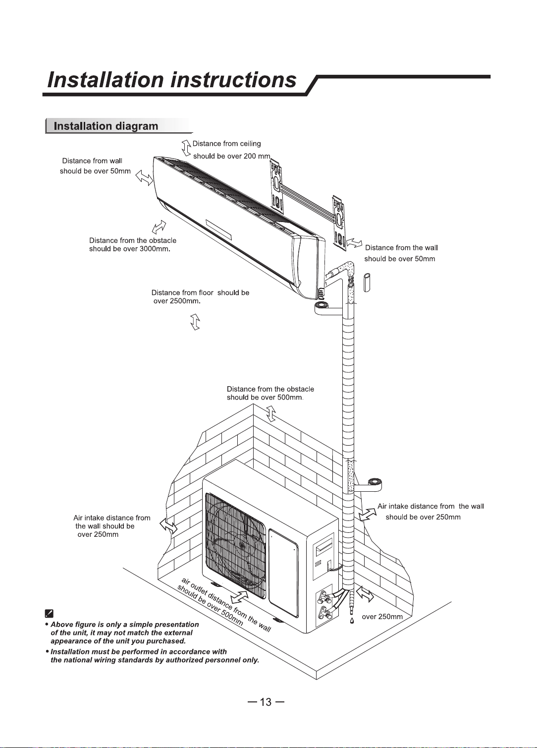
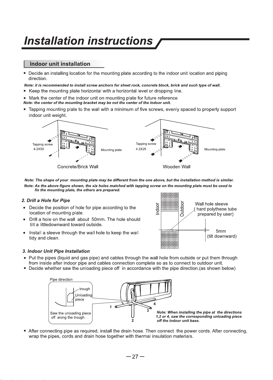
Installation
instructions/
•
Distance from wall
should
be
over
50mm
Distance from
the
obstacle
should be over 3000mm.
Air
intake distance from
the wall should
be
over250mm
Distance from floor should
be
over 2500mm.
-13-
should
be
over
50mm
Air
intake distance from the wall
should
be
over
250mm

Identification
of
parts/
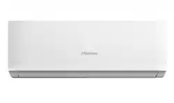
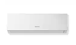
Indoor unit
Front Panel
Air
Intake
Display Panel
Emergency
Panel
Air Outlet
Horizontal
Adjustment
Louver
Air Filter
-----------------------~i-------
Remote
Controller
Outdoor unit
• The figures in this
manual
are
based
on the extemal view
of
a standard
model.
Consequently,
the
shape
may
dlll'er
from
that
of the air
condlUoner
you
have
selected.
-14-
Air
Intake
Pipes
and
Power
Connection
Cord
Drain Hose
Note: Condensate
-ter
drains
a.I
COOLING
ar
DRY
opel'llllan.
Air Outlet
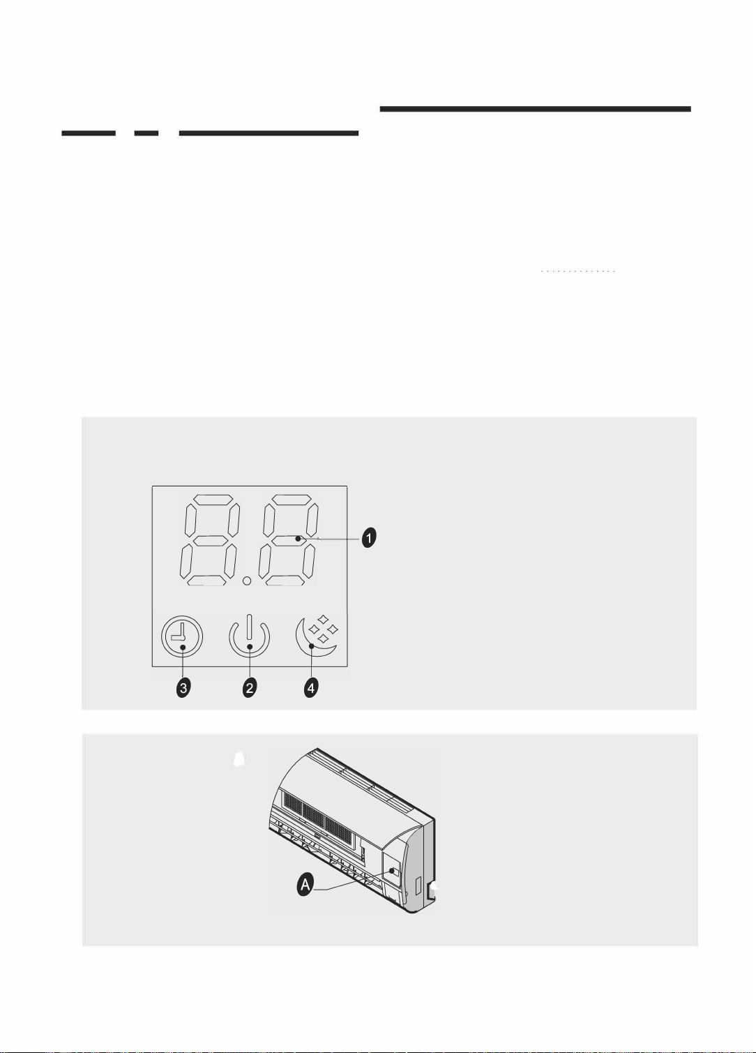
DisplayduconI
BB
Q
DJ
/ TV
series
e
一
。
。
e
。
-15-
Remote controller/
I Remote
controller
•
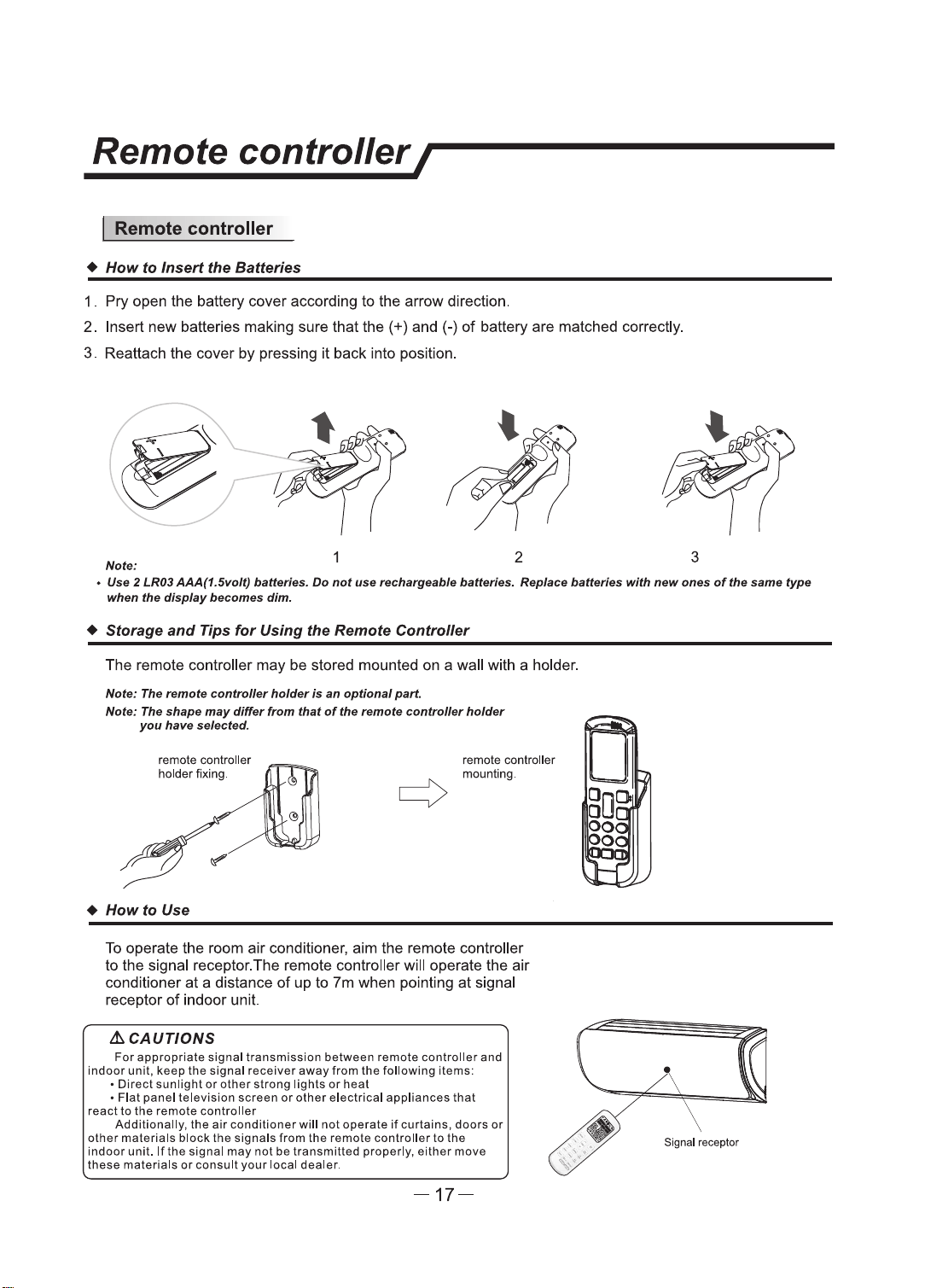
How
to Insert
the
Batteries
1 . Pry open
U'le
battery cover according to the arrow direction.
2. Insert new batteries making sure
U,at
the(+) and(-)
of
battery are matched
correcUy.
3. Reattach the cover by pressing it back into position.
Nata:
2 3
• Use 2
LR03
AAA(1.Slrolt)
bettrlnu.
Do
not
uu
rechatpable
betterlu.
Replac4I
betl9nu
with
new
onu
oftlle aame type
wflen
the
display
becomes dim.
• Storage
and
Tips
for
Using the Remote Controller
The remote controller may be stored mounted
on
a wall with a holder.
Nata: The remota
conttuller
'1oJder
Is
an
optional
part.
Note:
The
shape
may
differ
from
that
of
the
remo•
r:ontroller
holder
you
have
NIKted.
remote conlrcller
holder fixing.
•
How
to Use
remote controller
mounting.
To
operate the
room
air conditioner, aim the remote controller
to the signal receptor.The remote controller
will operate the air
conditioner
at
a distance
of
up
to
7m
when pointing at signal
receptor
of indoor unit.
lhCAUTIONS
For
appropriate signal transmission between remote controller and
indoor
unit, keep
the
signal receiver
away
from
the
following items:
• Direct sunllght
or
other
strong llghts
or
heat
•
Flat
panel television screen
or
other
electrical appliances
that
react
to
the
remote controller
Additionally,
the
air
conditioner
will
not
operate
if
curtains, doors
or
other
materlals block
the
slgnals from the remote controller
to
the
indoor
unit.
lflhe
signal
may
not
be
transmitted properly, either move
these
materlals
or
consult your local dealer.
-17-
Signel receptor
Operation instructions I
I Operation modes
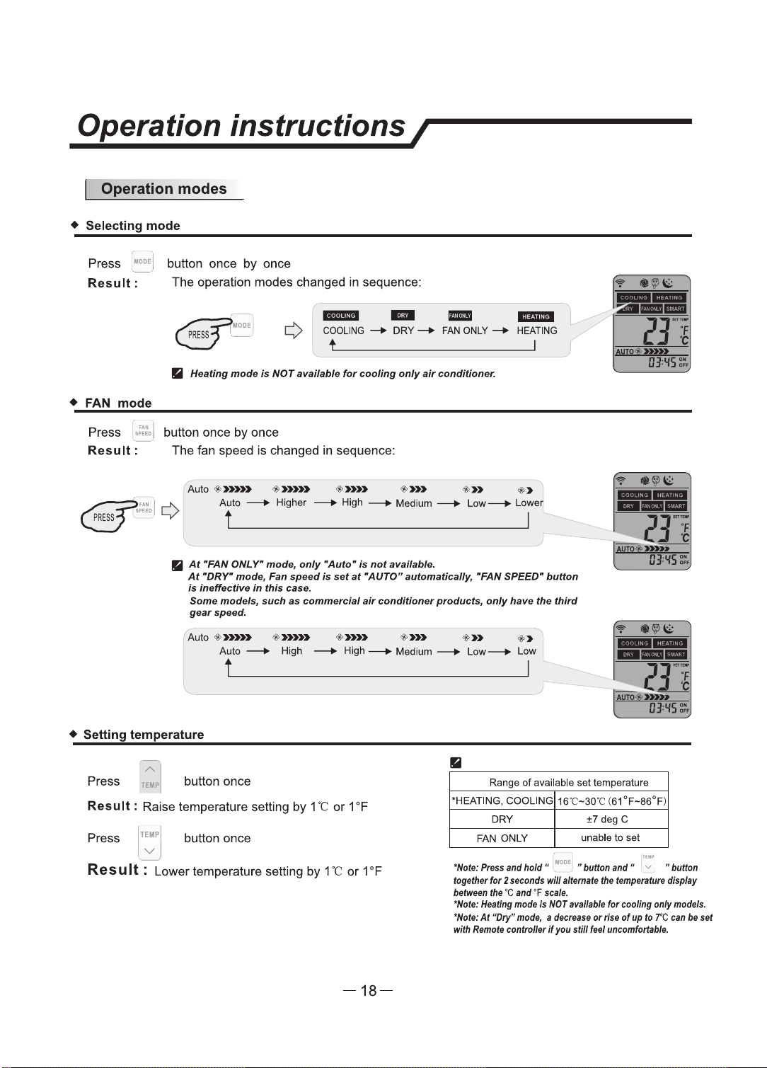
• Selecting
mode
Press 1_•
0
DE
, button once
by
once
Result:
The
operation modes changed
in
sequence:
- - -
-
COOLING
-+
DRY-+
FAN
ONLY-+
HEATING
•
HNtlng
mode
Is
NOT
anllflble
for
cooling
only
air
conditioner.
•
FAN
mode
Press
,:':..
I button once
by
once
Result:
The
fan speed
is
changed
in
sequence:
Auto
•»»> •»»>
·-
•»>
•»
•>
Auto
--+
Higher
--+High--+
Medium---+
low-+
Lower
II
At
•FAN ONL r
mode,
only
•Auto"
Is
not..,.,,.,,,._
At
•DRr
mode, t=.n
speed
Is
nt
at
·AuTOR
automaflAlly,
•FAN SPEED•
button
ia
ineffectin
in
this
can.
SoJH
models, IWt:h
as
commercial
air
t:Ondi6ontw products,
only
haw
the
third
gaerspeed.
Auto
·-·-
+»»
+»>
•»
+>
Auto ---+ High
---+
High
--+
Medium
--+
Low-+
Low
• Setting temperature
II
OJ.lfS:..
Press
~,
I button once
Range
of
avallable set temperature
Result
: Raise temperature setting
by
1
"C
or
1 °F
Press
TEMP
button once
v
\ /
Res u
It
: Lower temperature setting by 1
"C
or
1
°F
-18-
•HEATING, COOLING
16"C-30"C
(61°F-86°F)
DRY
±7degC
FAN ONLY
unable
to
set
"Note:
,.,..
lltld hold
-1
- 1
..
button
an11
• 71
..
buflan
m,eflltr
for
2
seconds
wlR
lltamlll
lfl•
flmp8munl dlsplay
b8tftWI
fire
'C
and
•F
ff8l9.
"Nof9:
Heallng
mow
Is
NOT
MMI,
for
eoollng only
models.
"Note:
At
"Dty"
mode,
I del:t8lle
or
rfff
ot
up
fD
7'C
tan
be
NI
with
lhmcill-lnlBerlf~
dllfNI
~
Operation instructions/
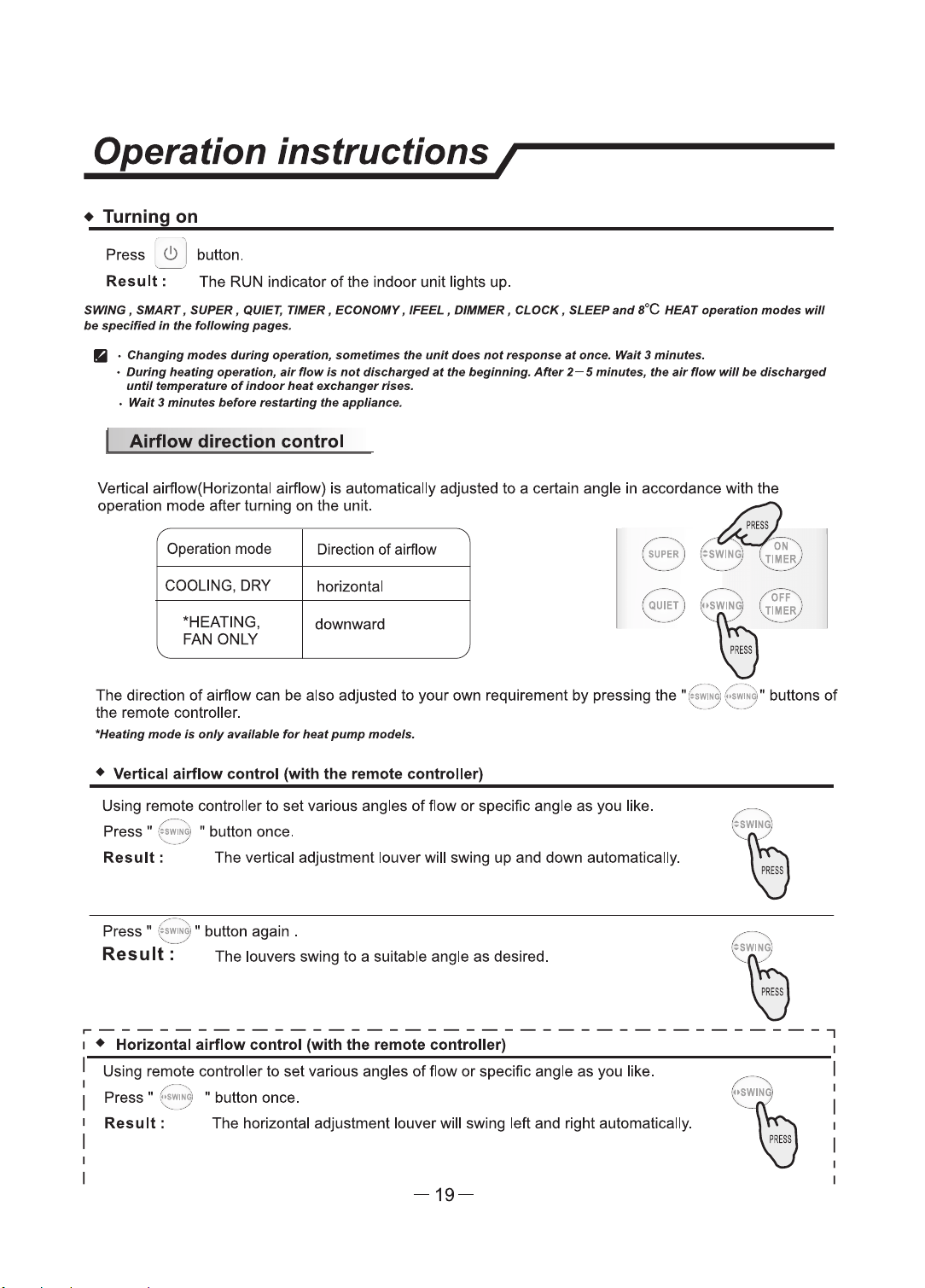
• Turning on
Press :
<!>
] button.
Result:
The RUN indicator
of
the indoor unit lights up.
SMNG,
SMART, SUPER, QUIET, 11MER, ECONOMY,
IFEEL,
DIMMER, CLOCK, SLEEP
and
l°C
HEAT operation
modea
wlll
be
specified
in
the
following,,.,,.._
Ii
·
Changing
modu
during
openrllon,
.ametlmell
tlle
unit
don
not
rnpanse
,rt
once.
Waif
3 minute&.
•
During
hNtlllfl
openrtton, air
flow,.
not
dlacha,ged
at
tlle
beginning.
After
2-S
minutes,
the
air flow
wlll
be
discharged
until
tempentun
of
Indoor
heat
exchanger
rfns.
•
wan
3
minutes
b8fonl
resfllrllng
the
appliance.
Airflow
direction
control
Vertical airflow(Horizontal airflow) is automatically adjusted
to
a certain angle in accordance with the
operation mode after turning on the unit.
dE2
PRESS
/----,\ /
',
.
oN
.,\
I
SUPER
J :
:SWING
)
1.
TIMER
J
Operation mode Direction of airflow
"----
.
__
_,/
,
....
__
--
~/
'-...:
....
_ -
__
.,,
/
COOLING, DRY
horizontal
"HEATING,
downward
FAN
ONLY
,,-,---,\
1~
0F,=
',
~~
~/
"'
'Y
The direction
of
airflow can
be
also adjusted
to
your
own
requirement
by
pressing the
"(
~~~
:i,f
;....~
,t buttons
of
the remote controller. '·-
_..
,
__
_...
"Hut/ng
mods
la
only
avalklble
fur
hNt
pump
models.
•
Vertical
airflow
control
(with
the
remote
controller)
Using remote controller
to
set
various angles
of
flow
or
specific angle
as
you like.
Press"
:~
,wi.
~: • button once.
Result:
The
vertical adjustment louver will swing
up
and down automatically.
Press •
~
~~
~
~
:
" button again .
Res
u
It
: The louvers swing
to
a suitable angle
as
desired.
~--------------------------------------,
1 •
Horizontal
airflow
control
(with
the
remote
controller)
1
I Using remote controller
to
set
various angles
of
flow
or
specific angle
as
you
like.
Result:
The horizontal adjustment louver will swing left and right automatically.
~---.....
/
'\
~
~
~
~
Press
~
(.
,;~
~1 " button once.
',
..
___
./
-19-
Operation instructions/
I
Press " :;;;;;~ w button again .
---
! Result:,,_---- The louvers swing
to
a suitable angle
as
desired.
(
~~
N
~
i
I NOTE:N
the
unit
doesn't
have
four
ways
airflow
function,
you
can
adjust
ib
I
I
horizontal
airflow
by
you,self..(invalid
for
some
models)
\J
1
1
---------------------------------------
•
[A)
Do
not
tum
tile
vertical adjuatment
louwtnl
manually, otll91WIH
malfunctlon
may
occur.
If
that
11app-,
tum
otr
tile
unit
first
and
cut
otr the
power
supply, tllen
rutoJ9
power
supply
8(1a/n.
[[J
It
Is
bder
not
to
let
the
vertical
adjustment
lounr
tilt
downward
for
a
long
rime at COOLJNG
or
DRY
mode
to
prevent
condennd
-•
lhJm drlpplng.
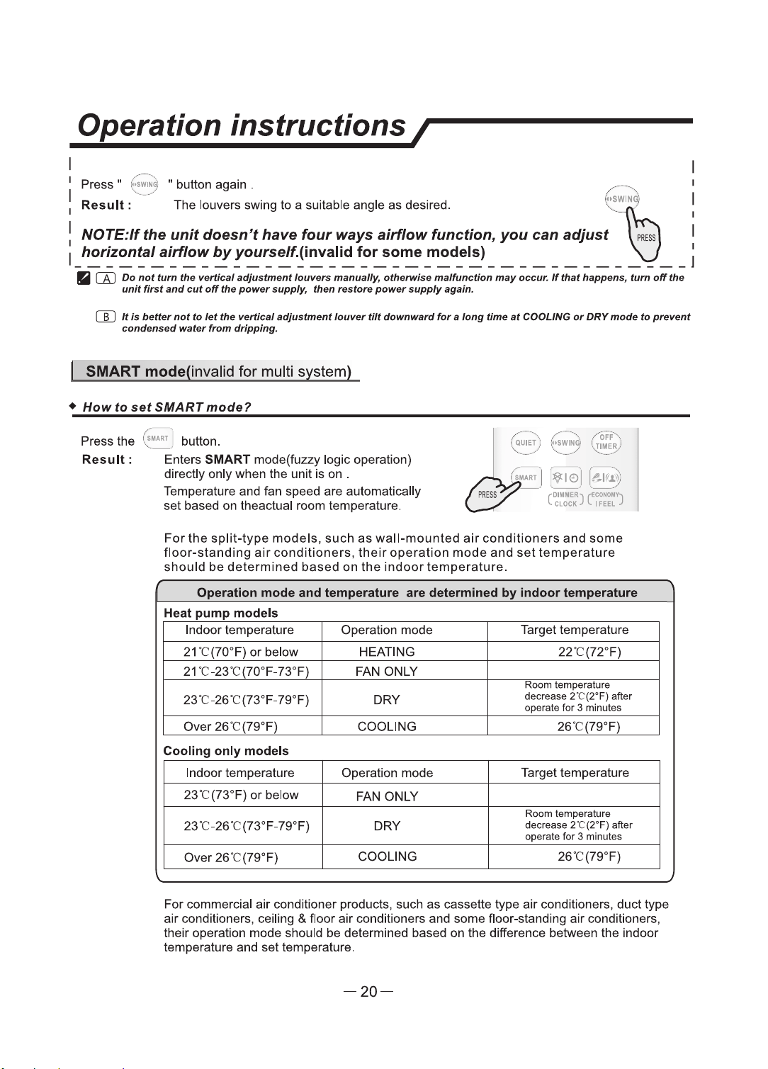
SMART mode(invalid for multi system)
•
HowtosetSMARTmode?
Press the
~
~~
J button.
Result:
Enters SMART mode(fuzzy logic operation)
directly only when the unit is on .
Temperature and fan speed are automatically
set based on theactual room temperature.
,r
;;;
J [
¥1e>
: [
&lf~
i
--
--
For
the
split-type
models,
such
as
wall-mounted
air
conditioners
and
some
floor-standing
air
conditioners,
their
operation
mode
and
set
temperature
should
be
determined
based
on
the
indoor
temperature.
Operation
mode
and
temperature
are
determined
by
indoor
temperature
Heat
pump
models
Indoor temperature Operation mode Target temperature
21
"C(70°F)
or
below HEATING 22
"C
(72°F)
21
"C-23"C(70°F-73°F) FAN ONLY
Room
temperature
23"C-26"C(73°F-79°F) DRY
decrease
2'C(2°F)
after
operate for 3 minutes
Over 26"C(79°F) COOLING 26"C(79°F}
Cooling
only
models
Indoor temperature Operation mode Target temperature
23"C(73°F}
or
below
FAN ONLY
Room
temperature
23"C-26"C(73°F-79°F) DRY
clec:rease
2
'C
(2°F) after
operate
for 3 minutes
Over 26'C(79°F)
COOLING 26"C(79°F)
For commercial
air
conditioner products, such as cassette type
air
conditioners, duct type
air
conditioners, ceiling & floor
air
conditioners and some floor-standing
air
conditioners,
their operation mode should be determined based on the difference between the indoor
temperature and set temperature.
-20-
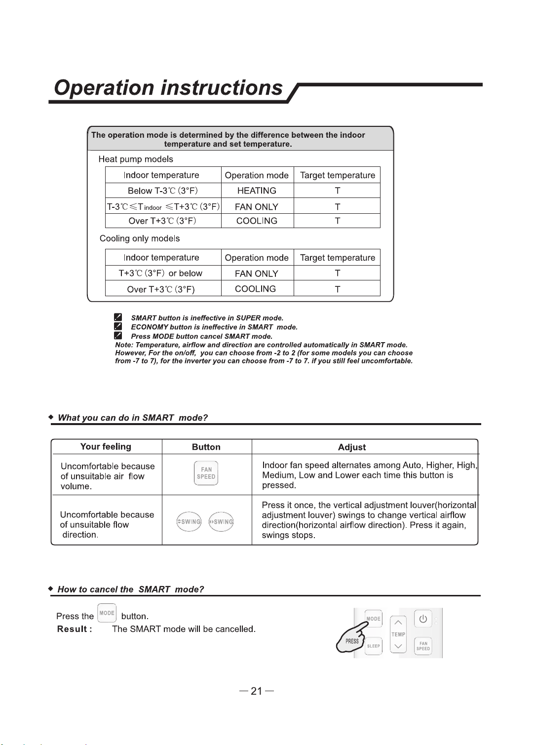
Operation instructions/
The operation mode
Is
determined
by
the difference between U,e Indoor
temperature and
set
temperature.
Heat pump models
Indoor temperature Operation mode Target temperature
Below T-3'C (3°F)
HEATING T
T-3
'C
~T1nc1oor
~T
+3'C (3°F)
FAN ONLY T
Over
T +3'C (3°F) COOLING T
Cooling only models
Indoor temperature Operation mode Target temperature
T+3'C (3°F)
or
below
FAN ONLY
T
over
T +3'C (3°F}
COOLING
T
• SIIIART
buttan
•
lllfllfuctlve
In
SUPER
mode.
• ECONOMY
buflon
la
ll'Hlll'ecllve fn SIIIART mode.
•
Preas
MODE
button
cam:e/
SMART
mode.
Noie: Temperature,
•ltffow
and
dlrectlon
•re
controlled
autom•tlct,lly In SMART
mode.
However,
For
the
on/off,
you
can
choose
from
-2
to 2
(for
.some
mode/a
you
can
choose
from
·7
to
7),
for
the
inverler
you
can
choa.e
from
·7
to
7.
if
you
still
feel uncomfortllble.
• What
you
can
do
In
SMART mode?
Your
feeling
Button
Adjust
Uncomfortable because
~ '
N I
Indoor fan speed alternates among Auto, Higher, High
of
unsuitable
air
flow
Medium,
Low
and Lower each time this button
is
volume.
, _ _ )
pressed.
Press
it
once, the vertical adjustment louver(horizontal
Uncomfortable because
,--
-·
,,
(/
- ··
--._
adjustment louver) swings
to
change vertical airflow
of
unsuitable flow
SWING
·,
I
OSWING
;
direction(horizontal airflow direction). Press
it
again,
'--.
____ 7
"-
/
direction.
--
swings stops.
•
How
to cancel the SMART mode?
~::
A
(!)
TEIIP
v
FAN
,..,m
Press the ,
1100
E,
button.
Result:
The SMART mode will
be
cancelled.
-21-
Operation instructions/
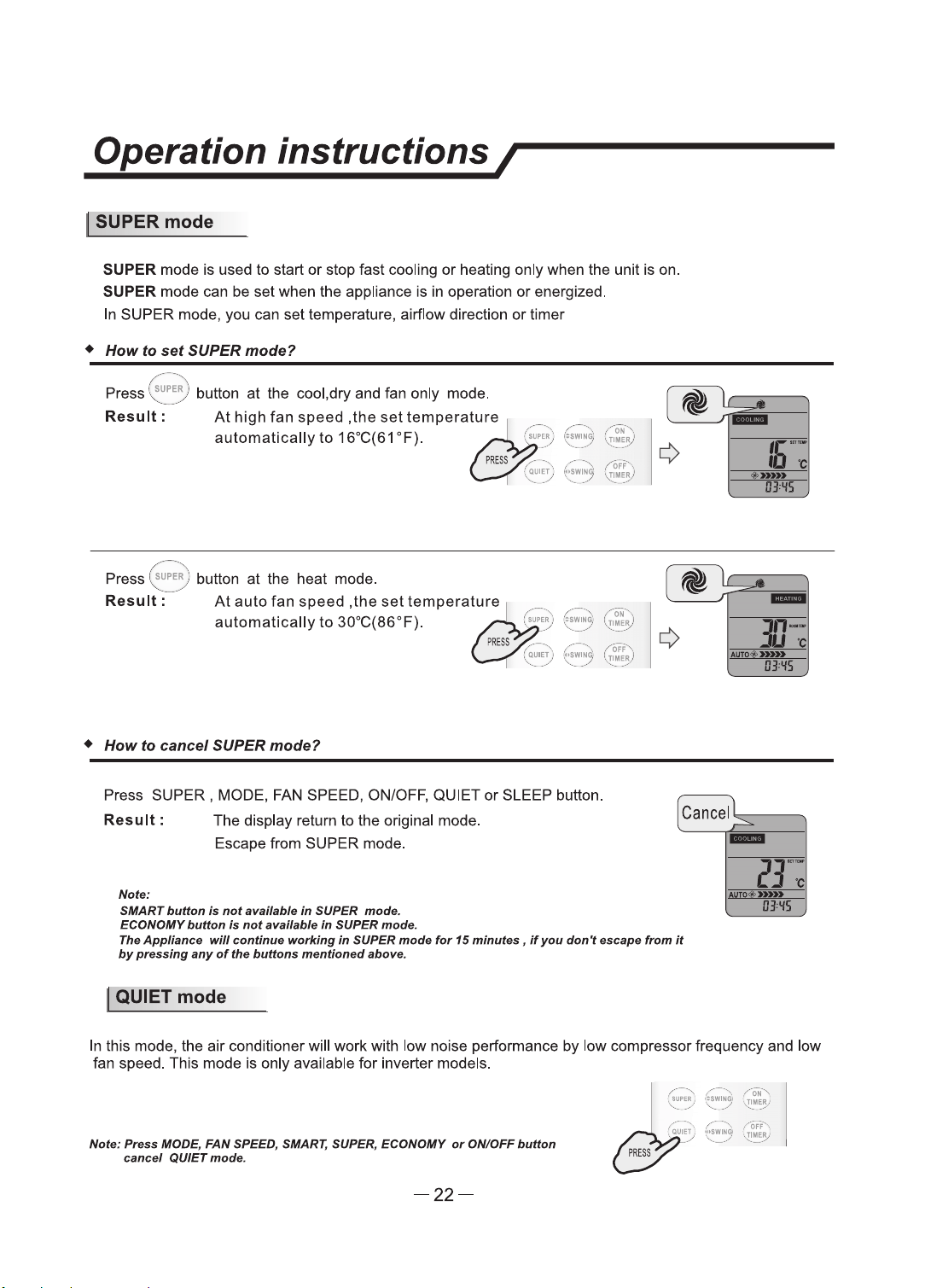
I SUPER
mode
SUPER mode is used
to
start
or
stop fast cooling
or
heating only when the unit
is
on.
SUPER mode can be set when the appliance is in operation
or
energized.
In SUPER mode, you can set temperature, airflow direction
or
timer
•
How
to
set
SUPER
mode?
,,----~,
Press
1
~au,E~:
button
at
the cool,dry and fan only mode .
......
___
.
Result:
At
high
fan
speed
,the
set
tempera~ture
,.
..•..
-
automatically
to
16°C(61 °F).
,:
....,.,
PRESS
,·--
(
QIJ1Ef
'::
-..
..
____
/
( '
Press ~
uPE~
) button
at
the heat mode.
Result=--
At
auto
fan
speed
,the
set
temperature
automatically
to
30°C(86°F).
•
How
to
cancel
SUPER
mode?
Press SUPER , MODE, FAN SPEED, ON/OFF, QUIET
or
SLEEP button.
Result:
Note:
The display return
to
the original mode.
Escape from SUPER mode.
SMART button
is
not
awilable
in
SUPER
mode.
ECONOMY
button
t.
not
alfllllable
In
SUPER
mode.
Tire
Appliana.
will
continl/9
working
in
SUPER
mode
for
15
minutu,
if
you
don't
escape
from
it
by
pnulng
any
of
the buttons mentioned above.
I QUIET
mode
-
JJ~
IJ)'fS
In this mode, the air conditioner will work with low noise performance by low compressor frequency and low
fan speed. This mode
is
only available for inverter models.
Nofle:
Ptutl
IIODE,
FAN
SPEED, SMART, SUPER.
ECONOMY
or
ON/OFF
button
cancel
QUIET
mode.
-22-
Operation instructions/
I
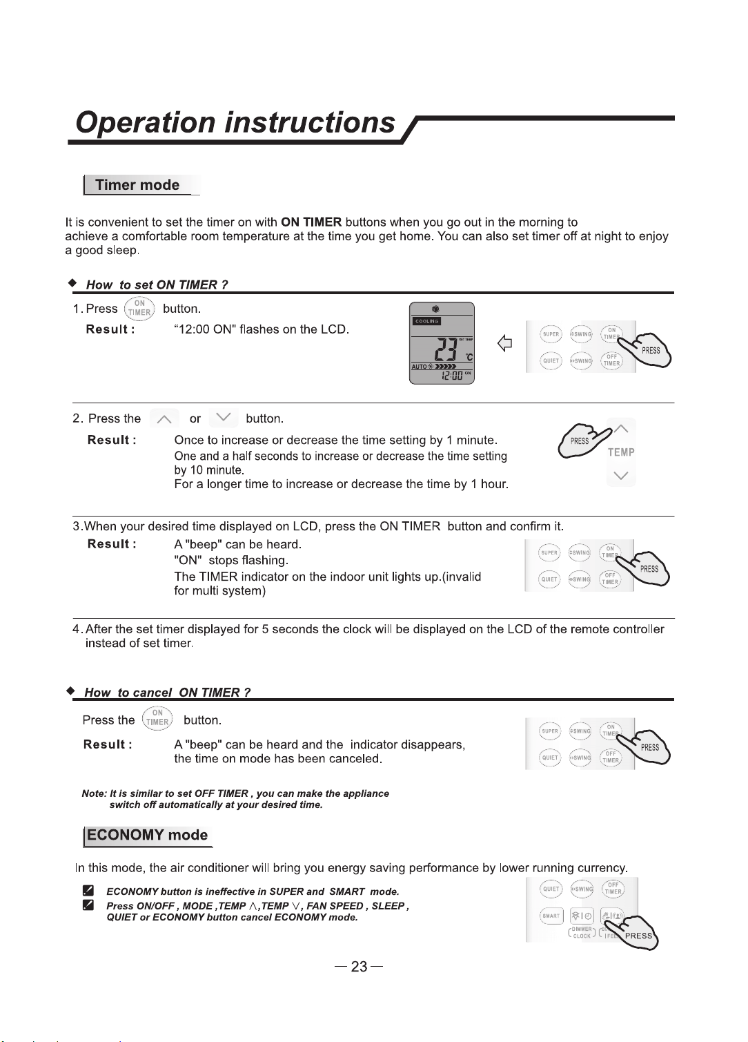
Timermode
It
is
convenient
to
set
the
timer
on
with
ON
TIMER buttons when you
go
out
in the morning
to
achieve a comfortable room temperature
at
the time you
get
home. You can also
set
timer
off
at
night
to
enjoy
a good sleep.
+
How
to
set
ON TIMER ?
•
.,.
ON
··,
1 .
Press
(
TIMER
) button.
-....:...
___
./
Result:
"12:00 ON" flashes
on
the
LCD.
-
2.
Press
the
A.
or
V button.
Result
:
Once
to
increase
or
decrease the time setting
by
1 minute.
One and a half seconds
to
increase
or
decrease the time setting
by
10 minute.
For
a longer time
to
increase
or
deaease
the time
by
1 hour.
~
A.
c:;.-"
TEMP
v
3.When
your
desired time displayed on LCD, press
the
ON
TIMER
button
and
confinn it.
Result
: A "beep" can be heard.
"ON" stops flashing.
The
TIMER indicator on the indoor unit lights up.(invalid
for
multi system)
4.
After the
set
timer displayed
for
5 seconds the clock will
be
displayed
on
the LCD of the remote controller
instead
of
set
timer.
+
How
to
cancel
ON
TIMER 1
/ ·
oN
··,._
Press
the
'
,;r
1~R,
) button.
Result:
A "beep" can be heard and the indicator disappears,
the
time on mode has been canceled.
Nate:
It
la
similar
to
nt
OFF
TIMER,
you
can
tnlllce
the
appliance
switch
off
aufomatlcally
at
your
dafred
time.
I ECONOMY mode
In
this mode, the
air
conditioner will bring
you
energy saving performance
by
lower running currency.
• ECONOMY
button
Is
Ineffective
In
SUPER
and
SMART mode.
•
Pntu
ON/OFF I
lllODE.
TEMP
/\,TEMP
v I
FAN
SPEED.
SLEEP.
QUIET
or
ECONOMY
button
cancel
ECONOMY
mode.
-23-

Operation instructions/
! IFEELmode
The
temperature sensor built in remote controller
is
activated.It can sense
its
surrounding temperature.and
transmit
the
signal back the unit,the unit can adjust
the
temperature
so
as
to
provide maximum comfort.
+
How
to
set
IFEEL mode ?
Press the [
&I«~
) button
for
about 5 seconds once.
Result
: The transmit signal in
the
display will appear,
the
IFEEL function will
be
started.
Nof.9:
111•
default
afHflng
la
lFEEL
lnactMng.
+
How
to
cancel
IFEEL mode?
Press the [ ' button
for
about 5 seconds once again.
Result:
IFEEL function will be shunted off.
I DIMMER
button
+
How
to
set
the DIMMER 1
Press the DIMMER button
to
tum
off
the light and
the
display in the unit.
Note:
When the
tight
Is off,recelve
signal
will
tum
on
the
tight
again.
I CLOCK
button
• How to
adjust
the
real
time?
1. Press [
\lie>
] button
for
about 5 seconds once.
Result:
The
time
flashes
on
the
LCD.
/,·-···,
..
...
,··-··,.
/"
Off
"·,
;
QUET
,'
'.
~
~g;
I.
Tlll!R
i
.......
-··
'·
....
./
.......
__
,,
•
-
2.
Press A and V buttons.
Result
: Once to increase
or
decrease the time setting
by
1 minute.
One
and
a
half
seconds
to
increase
or
decrease
the
time
setting
by 10 minute.
~ A
C/'
TEMP
For
a longer time
to
increase or decrease the time
by
1 hour.
v
'
3.
Press
91e:>
button once again.
•
Result
:
The
real time is set.
-
-24-
Operation instructions/
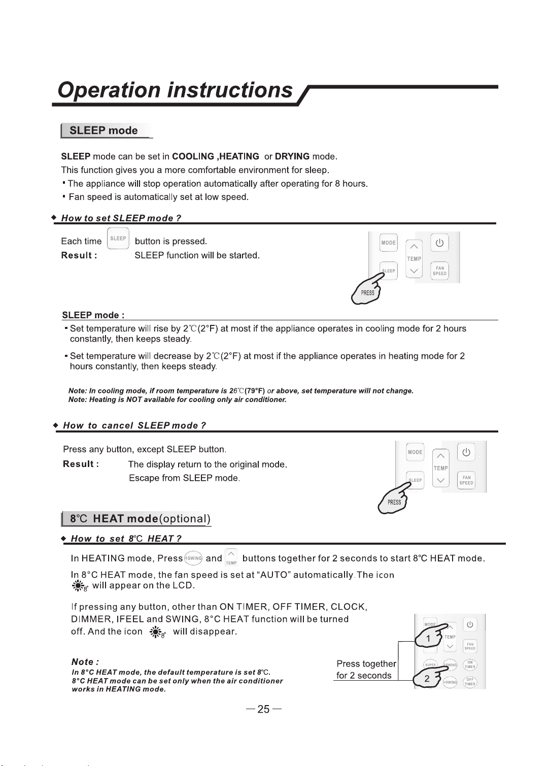
I SLEEPmode
SLEEP mode can be set
in
COOLING ,HEATING
or
DRYING mode.
This function gives you a more comfortable environment
for
sleep.
• The appliance will stop operation automatically after operating for 8 hours.
• Fan speed is automatically
set
at
low speed.
•
How
to
set
SLEEP
mode
1
Each time
aLEEP
I button
is
pressed.
',
/
Result:
SLEEP function will be started.
SLEEP
mode:
,
IODE
.1
A
I
e!>
TEIIP
v
[
·="ED
I
• Set temperature will rise by
2t(2°F)
at most
if
the appliance operates in cooling mode
for
2 hours
constantly, then keeps steady.
•
Set
temperature will decrease by
2t
(2°F)
at
most
if
the appliance operates in heating mode
for
2
hours constantly, then keeps steady.
Note:
In
r:oollng
mode,
If,_,
frlmPfllllfunt
/a
26"C(79"F)
or
&ban,
nt
tamp11T11tun
will
not
change.
Note:
HNtlng
la
NOT
avaflabls
for
cooling
only
air
conditioner.
•
How
to
cancel
SLEEP
mode ?
Press any button, except SLEEP button.
Result
: The display return to the original mode.
Escape from SLEEP mode.
I 8"C HEAT
mode(optional)
•
How
to
set
8°C
HEAT?
IIIODE
A
TEIIIP
v
,.--...
. . A .
In HEATING
mode,
Press
~~15
1
and
TE•
buttons
together
for
2
seconds
to
start
8°C HEAT mode.
In
8°C
HEAT mode,
the
fan
speed
is
set
at
"AUTO"
automatically.The
icon
+ir
will
appear
on
the
LCD.
If
pressing
any
button,
other
than
ON TIMER,
OFF
TIMER,
CLOCK,
DIMMER,
IFEEL
and
SWING,
8°C
HEAT
function
will
be
turned
off.
And
the
icon
.If
will
disappear.
Note:
In
re
HEAT mode,
the
default
temperature
is
set
re.
B°C
HEAT
mods
can
be
sat
only
when
the
air
conditioner
works
In
HEATING
mode.
-25-
Press together
for 2 seconds
son inscons /
I
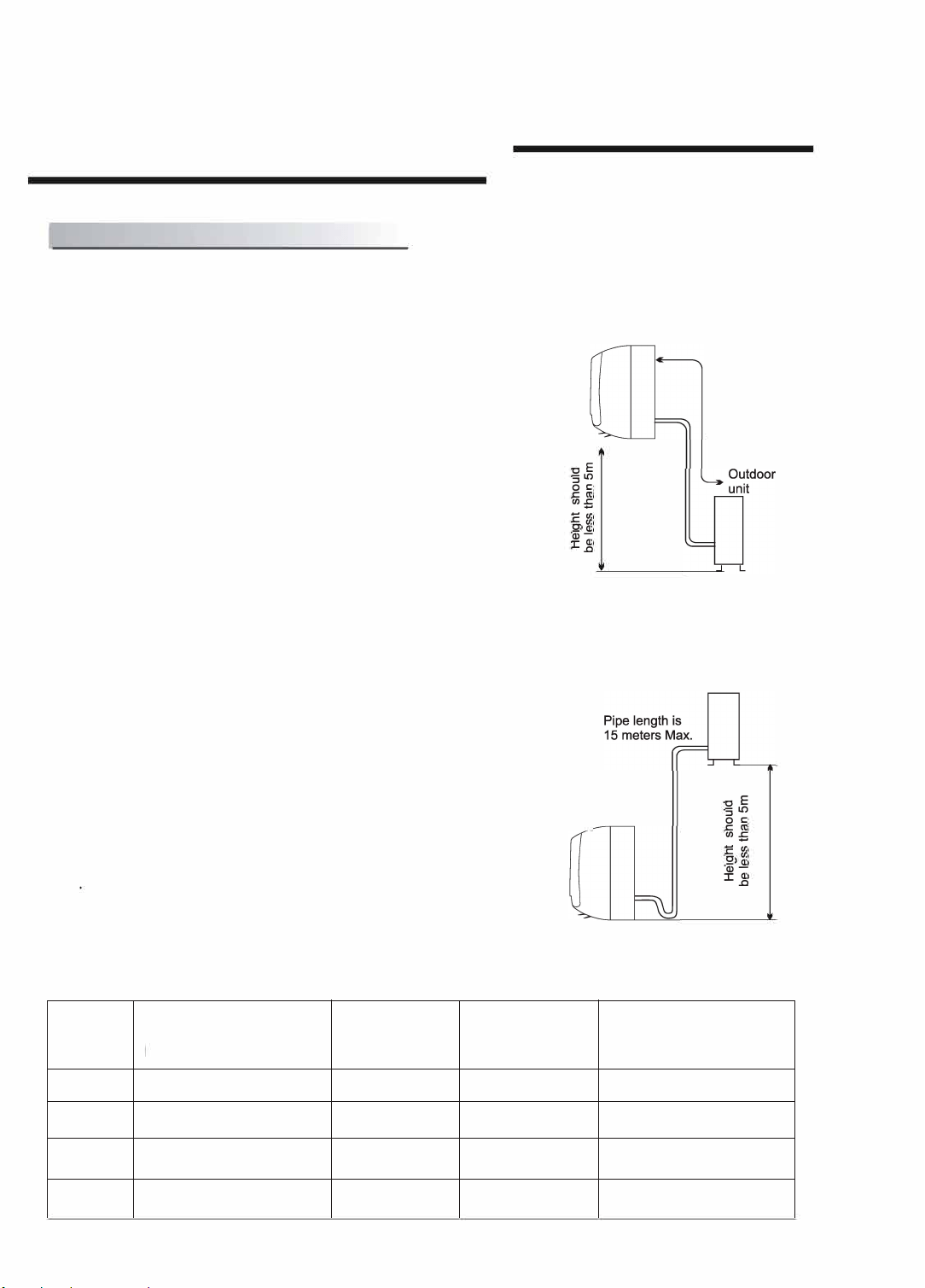
Select the installation locations
Eg
ue41
ssa1
aq
p1no4s
1461aH
15 Max.
Eg
ue41
ssa1
aq
p1no4s
1461aH
10
8
-26-
Instation strucons
/
巨i
>
二
p
二
n
g
刁
7.1KW,8.0KW,9.0 KW
7.1KW,8.0KW,9.0 KW
-28 -
son inscons /
nn
nnehe ee nnnnen
he ehe enn he nn
n ne h he nnnen
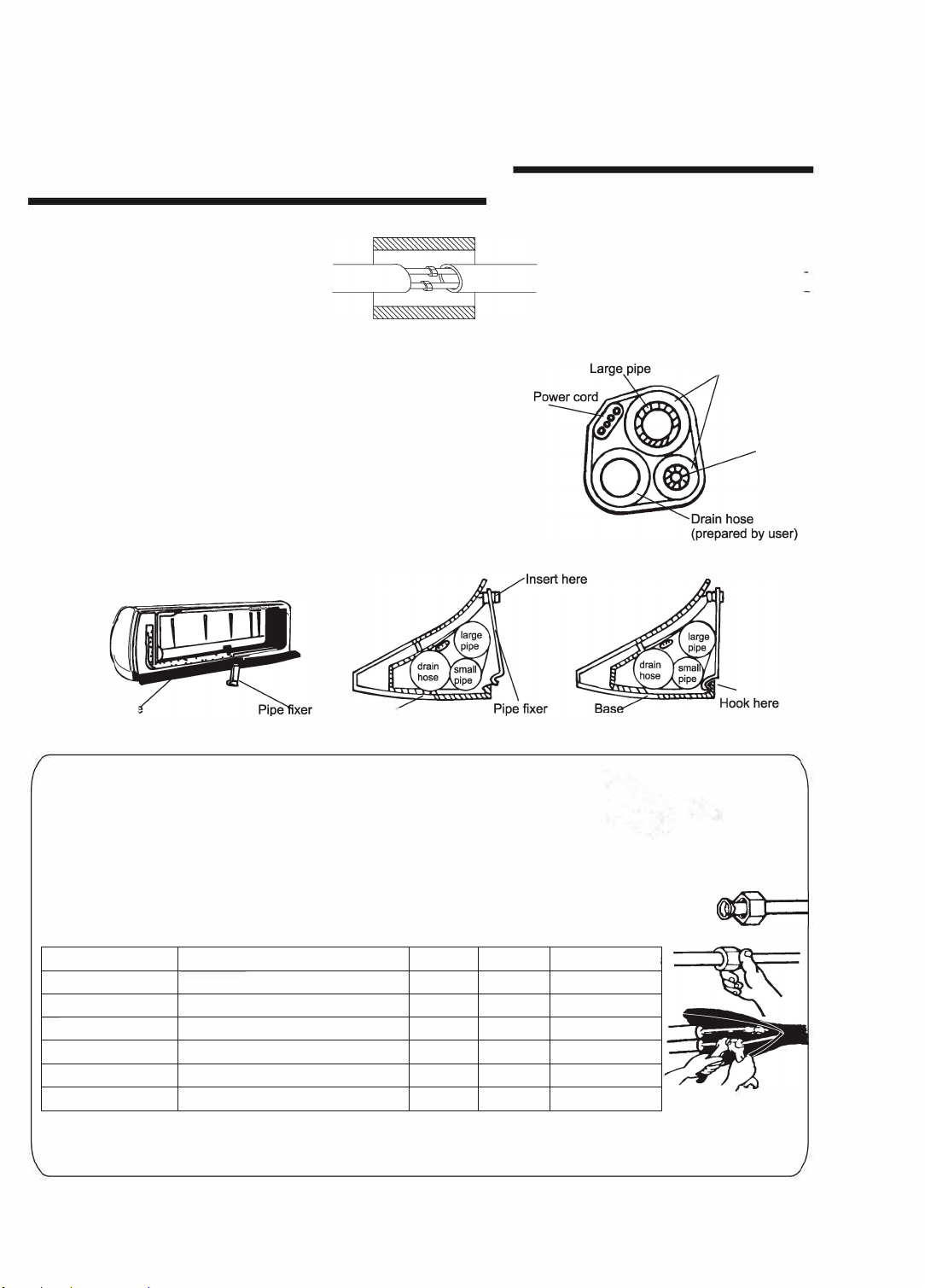
Note: For some models, it is necessary to remove the cabinet to
connect to the indoor unit te『minal.
n
ee he ee nenn
he ennee ehe enn he
nn
ee he enhe n
h e
enhe ehe nn
h he e
=
nn
n
e eneeeeeeen
h
$尽骂嘉芦言
n
e
l
n
eehe n neehe nnehe eh
neehe en he ne he e
hhe e hneeen he ee en
hehe ene e hhee heneee nnen
e e nn eh ee een ee
2
2
2
2
8
2
-29-
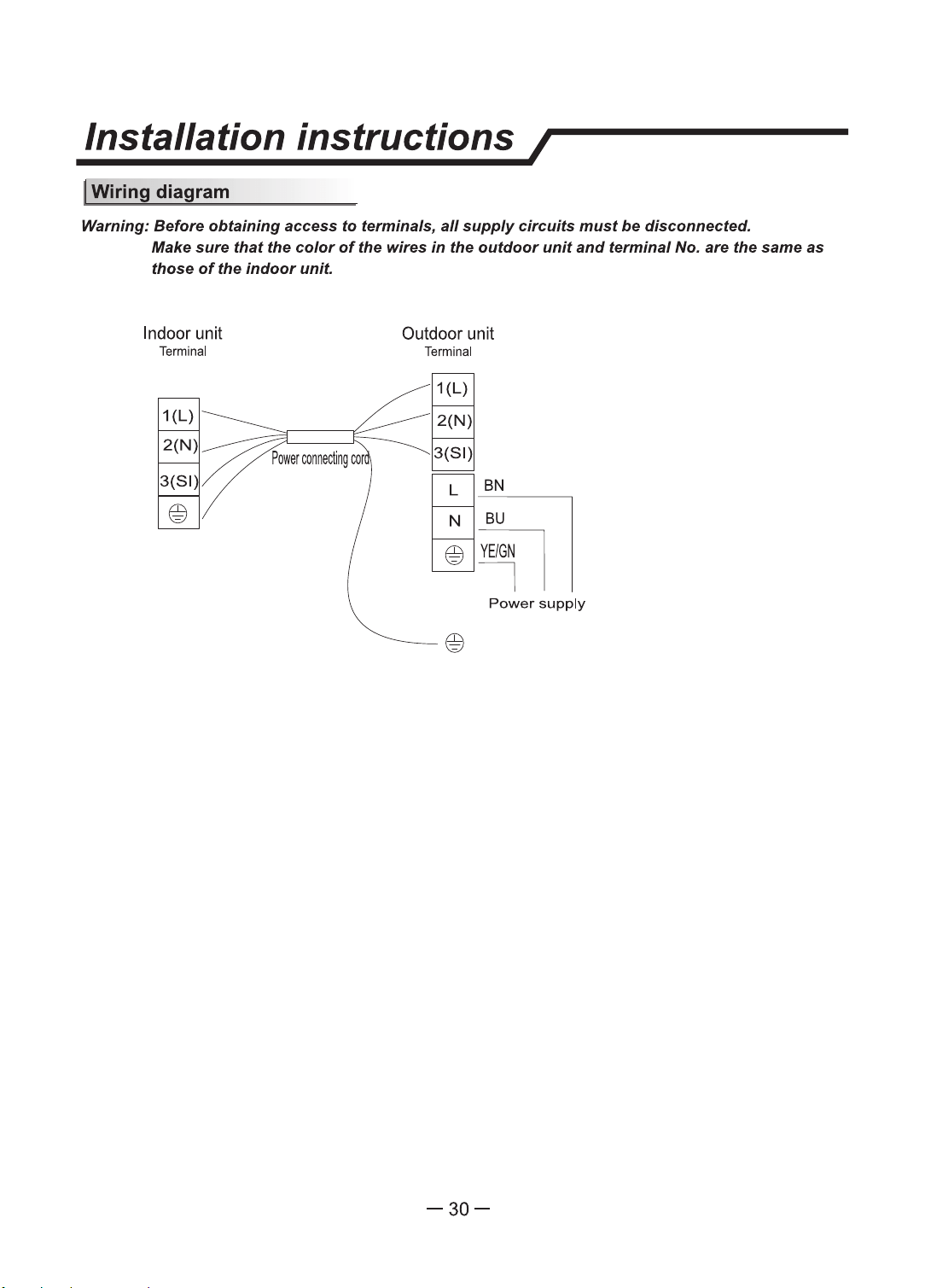
Warning: Before obtaining
access
to
terminals, all
supply
circuits
must
be disconnected.
Make sure
that
the
color
of
the wires
in
the
outdoor
unit
and terminal No. are the same
as
those
of
the
indoor
unit.
Indoor unit
Terminal
Outdoor unit
Terminal
1{L)
BN
~
Power
supply
-30-
Installation instructions /
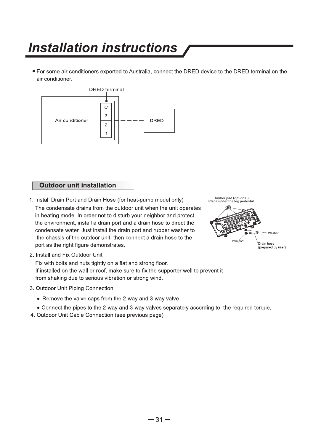
• For some air conditioners exported to Australia, connect the DRED device
to
the DRED terminal on the
air conditioner.
DRED
termlnal
Air
conditioner
~
---Fl
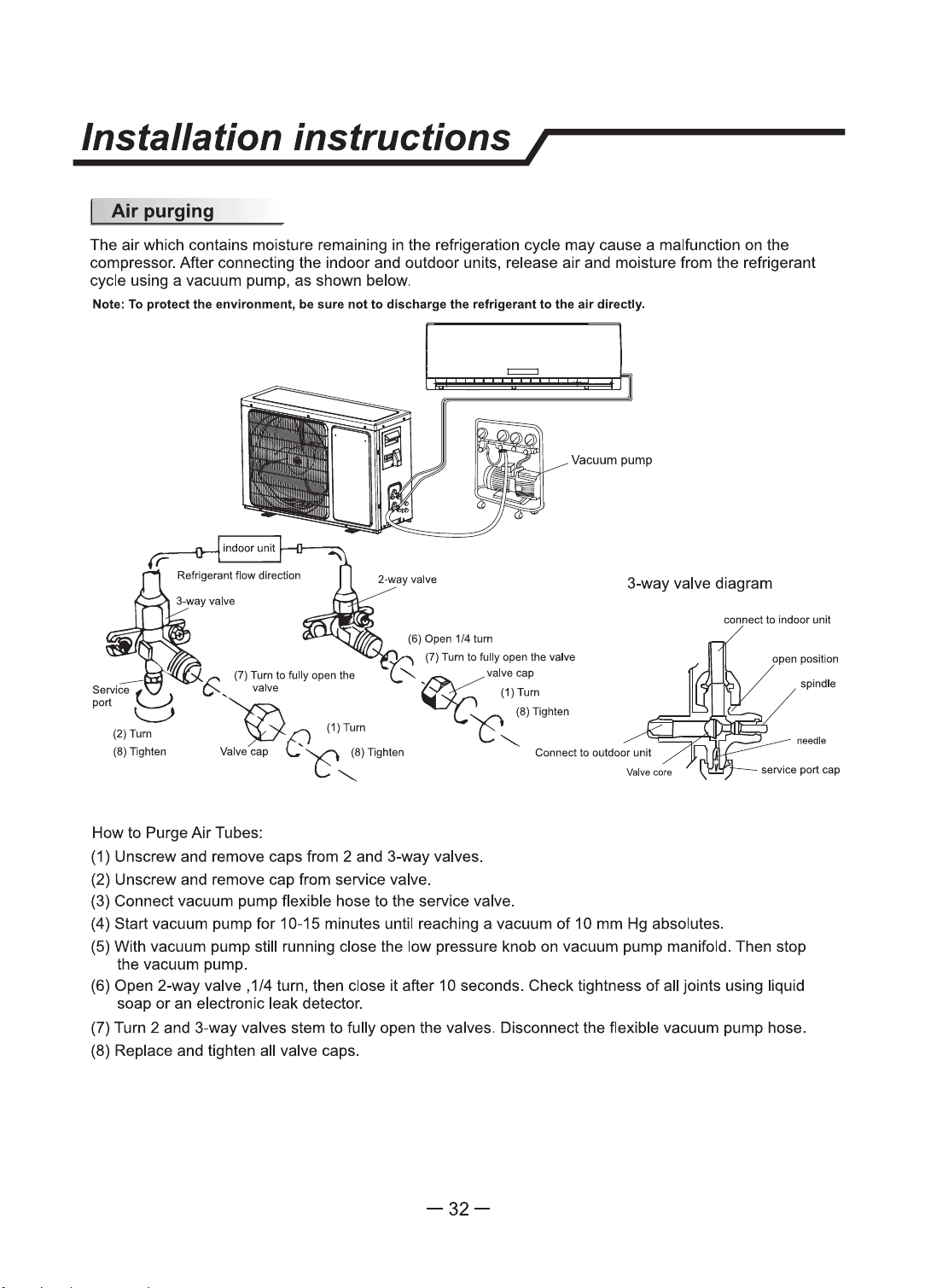
1. Install Drain Port and Drain Hose (for heat-pump model only)
The condensate drains from the outdoor unit when the unit operates
in heating mode. In order not to disturb your neighbor and protect
the environment, install a drain port and a drain hose to direct the
condensate water. Just install the drain port and rubber washer to
the chassis
of
the outdoor unit, then connect a drain hose to the
port as the right figure demonstrates.
2. Install and Fix Outdoor Unit
Fix with bolts and nuts tightly on a flat and strong floor.
Rubber pad (optional)
Place under
the
leg pedestal
/~Washer
Drain
port
\ _
..
Drainhoaa
(praparad by uoer)
If
installed on the wall
or
roof, make sure
to
fix
the supporter well to prevent
it
from shaking due
to
serious vibration
or
strong wind.
3.
Outdoor Unit Piping Connection
• Remove the valve caps from the 2-way and 3-way valve.
• Connect the pipes
to
the 2-way and 3-way valves separately according
to
the required torque.
4. Outdoor Unit Cable Connection (see previous page)
-31-
Installation
instructions/
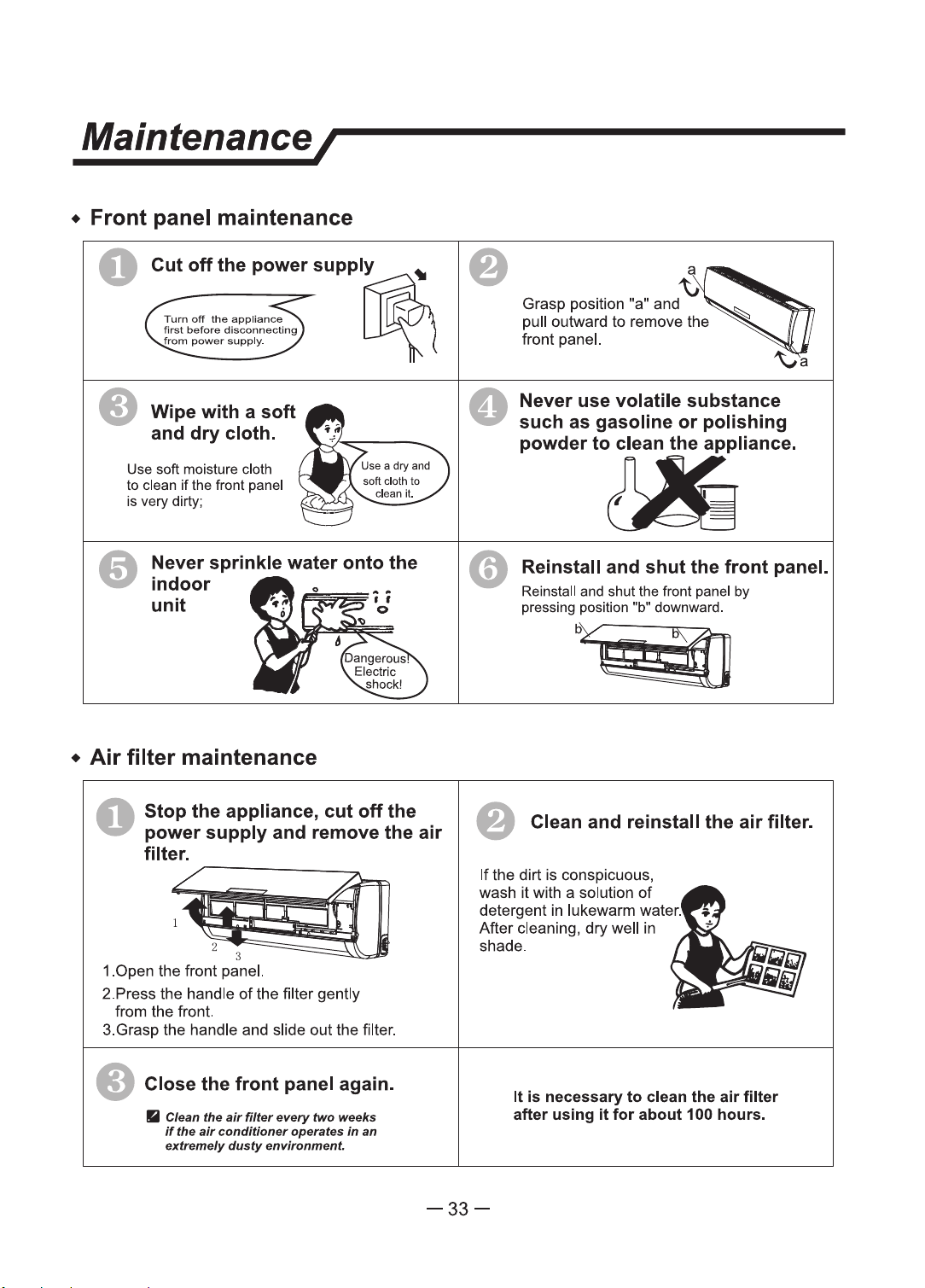
The
air
which contains moisture remaining in the refrigeration cycle
may
cause a malfunction on the
compressor. After connecting the indoor and outdoor units, release air and moisture from the refrigerant
cycle using a vacuum pump, as shown below.
Note: To protect the environment, be aura
not
to discharge the refrigerant to the
air
directly.
=
Vacuum pump
3-way valve diagram
(7)
Tum
to fully
open
the
valve
·~
(7) Tum to
fully
open
the
(,"
valve
"©
(1)Tum
......._
valve cap
~
(1)Tum
.......
c?c'
.:·-
'-'t
~
~8)
lighten
How to Purge
Air
Tubes:
(1) Unscrew and remove caps from 2 and 3-way valves.
(2) Unscrew and remove cap from service valve.
(3) Connect vacuum pump flexible hose to the service valve.
Connect
to
outdoor
unit
(4) Start vacuum pump
for
10-15 minutes until reaching a vacuum
of
10
mm Hg absolutes.
oonnect to indoor unit
open
position
spindle
needle
service port
cap
(5) With vacuum pump still running close the low pressure knob on vacuum pump manifold. Then stop
the vacuum pump.
(6) Open 2-way valve , 1/4 tum, then close it after 1 O seconds. Check tightness of all joints using liquid
soap
or
an electronic leak detector.
(7) Turn 2 and 3-way valves stem
to
fully open the valves. Disconnect the flexible vacuum pump hose.
(8) Replace and tighten all valve caps.
-32-
Maintenance/
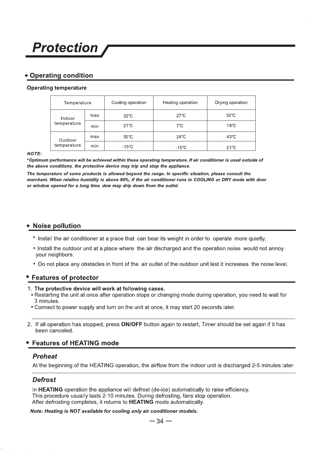
• Front panel maintenance
0
• Wipe
with
a
soft
and
dry
cloth.
Use
soft moisture cloth
to
clean
if
the front panel
is very dirty;
Never sprinkle water
onto
the
indoor
unit
•
Air
filter
maintenance
O
Stop
the appliance,
cut
off
the
power
supply
and remove the
air
filter.
~
1~
1.0pen
the
front panel.
2.Press
the
handle
of
the filter
gently
from
the
front.
3.Grasp the handle and slide
out
the filter .
• Close the
front
panel again.
• Clean the
air
filter
every"
two weeks
If
the
air
conditioner
operates
In
an
extremely
dusty
environment
0
~
Grasp
position "a" and
pull outward
to
remove
the
front panel.
Never use volatile substance
such as gasoline
or
polishing
powderto~llance.
Reinstall and
shut
the
front
panel.
Reinstall
and
shut the front panel by
pressing position "b" downward.
o/@
• Clean and reinstall the
air
filter.
If
the
dirt
is
conspicuous,
wash
it
with a solution
of
detergent in lukewann water.
After
cleaning,
dry
well in
shade.
It
is necessary
to
clean the air filter
after
using
it
for
about
100 hours.
-33-
Protection I
• Operating
condition
Operating temperature
Temperature
Cooling
operation
Heating
operation
Drying
operation
Indoor
max
32"C
27"C
32"C
temperature
min
21"C 7"C 18"C
max
50"C
Outdoor
24"C 43"C
temperature
min
-15"C
-15"C
21"C
NOTE:
~optimum perfonnam:e will
be
achieved within these operating temperature.
If
air
conditioner Is
used
outside
of
the above conditions, the protective device
may
trip
and
stop the appliance.
The temperature
of
some
products
is
allowed
beyond
the range. In specific situation,
please
consult the
merchant. When relative humidity
is
above
BO%.
if
the
air
conditioner runs in COOLING
or
DRY
mode with
door
or
window
opened
for
a
long
time,
dew
may
drip
down
from
the
outlet.
• Noise
pollution
' Install the air conditioner
at
a place that can bear its weight in order to operate more quietly.
• Install the outdoor unit
at
a place where the air discharged and the operation noise would not annoy
your neighbors.
• Do not place any obstacles in front
of
the air outlet
of
the outdoor unit lest
ii
increases the noise level.
• Features
of
protector
1.
The
protective
device
wlll
work
at
following
cases.
• Restarting the unit at once after operation stops
or
changing mode during operation, you need to wail for
3 minutes.
• Connect to power supply and tum
on
the unit at once, it may start 20 seconds later.
2.
If
all operation has slopped, press ON/OFF button again to restart, Timer should be set again
if
it has
been canceled.
• Features
of
HEATING mode
Preheat
At
the beginning
of
the HEATING operation, the airflow from the indoor unit is discharged 2-5 minutes later.
Defrost
In
HEATING operation the appliance will defrost (de-ice) automatically to raise efficiency.
This procedure usually lasts 2-10 minutes. During defrosting, fans stop operation.
After defrosting completes, it returns to HEATING mode automatically.
Note: Heating
is
NOT available
for
cooling
only
air
conditioner models.
-34-
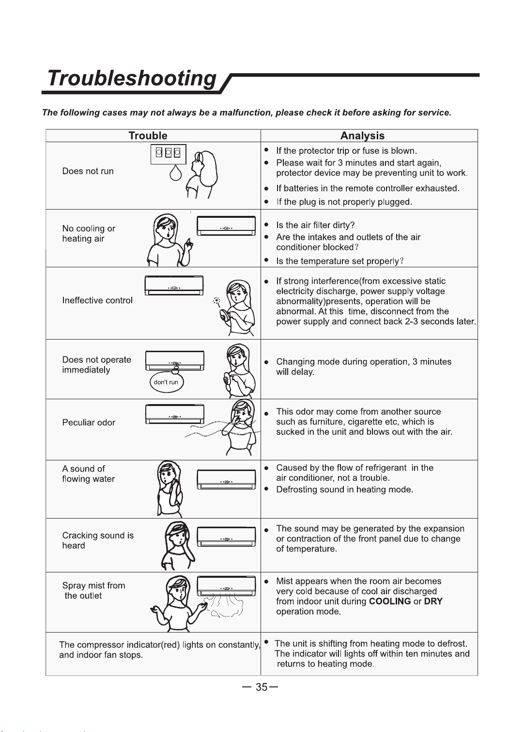
Troubleshooting I
The
following
cases
may
not
always
be
a malfunction, please
check
it
before asking
for
service.
Trouble
Anal
sis
[ITTrnl
ff\
Does
not
run O
R--1
•
If
the protector trip
or
fuse
is
blown.
• Please wait
for
3 minutes and start again,
protector device
may
be
preventing unit to work.
No cooling
or
heating
air
Ineffective control
•
If
batteries in
the
remote controller exhausted.
•
If
the plug
is
not
properly plugged.
I
..
""
..
j • Is the
air
filter dirty?
tr·
===
~~
~==
;;:j
, • Are the intakes and outlets
of
the air
conditioner blocked?
~-
'
..
, .1,
..
• Is the temperature set properly?
•
If
strong interference(from excessive static
electricity discharge,
power
supply voltage
abnormality)presents, operation will
be
abnormal.
At
this time, disconnect from the
power supply and connect
back
2-3 seconds later.
Does
not
operate
~
immediately
··
·
don~
run
• Changing
mode
during operation, 3 minutes
will delay.
Peculiar
odor
A sound
of
flowing water
I,
••
[:!
••
• This
odor
may
come from another source
such
as
furniture, cigarette etc, which is
sucked in the unit and blows
out
with the air.
• Caused by the flow
of
refrigerant in the
-..
I.
-~~-
....
, j aDirfcon~itioner,
ndo~
ahtro~ble. d
• e rostmg soun m eating
mo
e.
Cracking sound is
heard
I I
•
The sound
may
be
generated
by
the expansion
;
.__,.
, =
---.u
'
or
contraction
of
the front panel due to change
of
temperature.
Spray
mistfrom
the outlet
I
•
Mist appears when the room air becomes
t:=~
~:=::
+==.r11
. very cold because
of
cool air discharged
from indoor unit during
COOLING
or
DRY
operation mode.
The compressor indicator(red) lights
on
constantly, • The unit
is
shifting from heating
mode
to defrost.
and indoor fan stops. The indicator will lights
off
within ten minutes and
returns
to
heating mode.
-35-