Loading ...
Loading ...
Loading ...
5
the exact type of material to be used. The installation of
unions on the inlet and outlet water lines and a shut-off
valve in at least the cold water line is recommended so
the water heater may be easily disconnected for servic-
ing. Dielectric unions are not required for protection of
the water heater.
When this water heater is supplying general purpose hot
water requirements for use by individuals, a thermostati-
cally controlled mixing valve is recommended to reduce
the risk of scald injury. Contact a licensed plumber or
the local plumbing authority for further information.
Thermometer(s) should be installed so that they indicate
the temperature of the water at or near the outlet of the
water heater and storage tank(s) if provided. See Fig. 2
or 3.
4. RELIEF VALVE — A new combination pressure and
temperature relief valve, complying with the Standard
for Relief Valves and Automatic Gas Shutoff Devices
for Hot Water Supply Systems, ANSI Z21.22, is factory
installed on this water heater at the time of manufacture.
No valve is to be placed between the relief valve and the
water heater. For a circulating tank installation, the sepa-
rate storage tank(s) must have similar protection. Local
codes shall govern the installation of relief valves.
The pressure rating of the relief valve must not exceed
150 psi (1034kPa)(160 psi (1103kPa) for ASME models)),
the maximum working pressure of the water heater as
marked on the rating plate. The Btu/h rating of the relief
valve must not be less than the input rating of the water
heater as indicated on the rating plate located on the
front of the heater. (1 watt = 3.412 Btu/h).
Connect the outlet of the relief valve to a suitable open
drain so that the discharge water cannot contact live
electrical parts. The discharge line must pitch downward
from the valve to allow complete draining (by gravity) of
the relief valve and discharge line and be no smaller than
the outlet of the valve. The end of the discharge line
should not be threaded or
concealed and should be protected from freezing. No
valve of any type, restriction or reducer coupling should
be installed in the discharge line. Local codes shall govern
the installation of relief valves.
5. TO FILL WATER HEATER — Make certain drain valve is
completely closed. Open shut-off valve in cold water sup-
ply line. Open each hot water faucet slowly to allow air to
vent from the water heater and piping. A steady flow of
water from the hot water faucet(s) indicates a full water
heater.
Installation
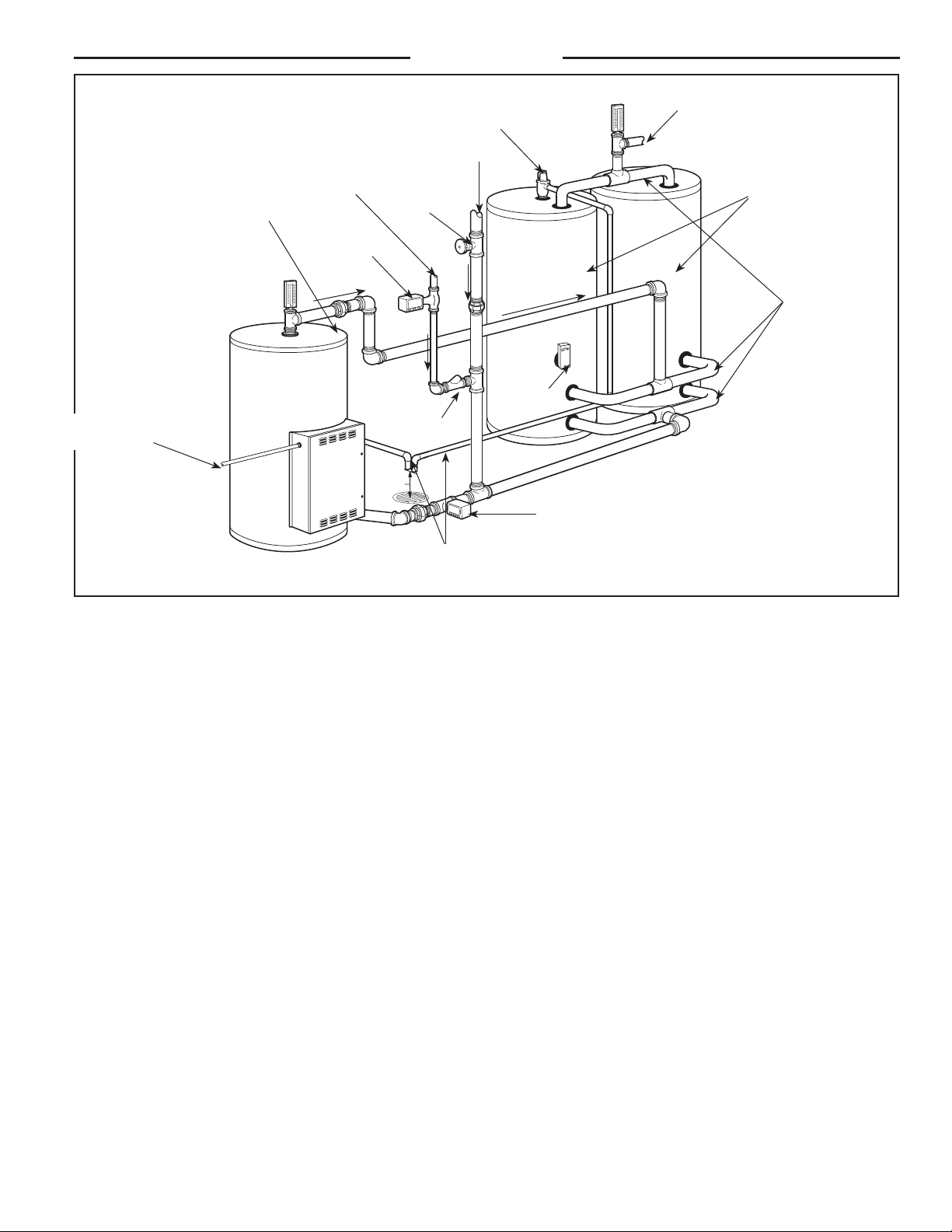
Figure 3. — Typical Forced Circulation Tank System with factory supplied jacketed and insulated storage tanks.
Temperature & Pressure Relief Valve
(Not visible in this view)
Refer to Local Codes
Storage Tank Temperature & Pressure Relief Valve
Refer to Local Codes
Temperature & Pressure Relief Valve(s)
Discharge Pipe(s) to suitable open drain
Branch Circuit from
Electrical Distribution Panel
Circulator*
* Circulator may be wired to run con-
tinuously without the control
Circulator
Control
(Optional*)
Manifolds
Cold Water Inlet
Shut-off Valve
Air Gap
6” (152mm)
Check Valve
Recirculation Loop
Recirculator
Storage Tanks
Hot Outlet
Vacuum Relief Valve
(Not visible in this view)
If required by local codes
Loading ...
Loading ...
Loading ...