Loading ...
Loading ...
3
Important Warnings
Installation
• Do not drill into or attempt to open any part of the PDU housing. There are no user-
serviceable parts inside.
• Do not attempt to use the PDU if any part of it becomes damaged.
• Use of this equipment in life support applications where failure of this equipment can
reasonably be expected to cause the failure of the life support equipment or to
significantly affect its safety or effectiveness is not recommended.
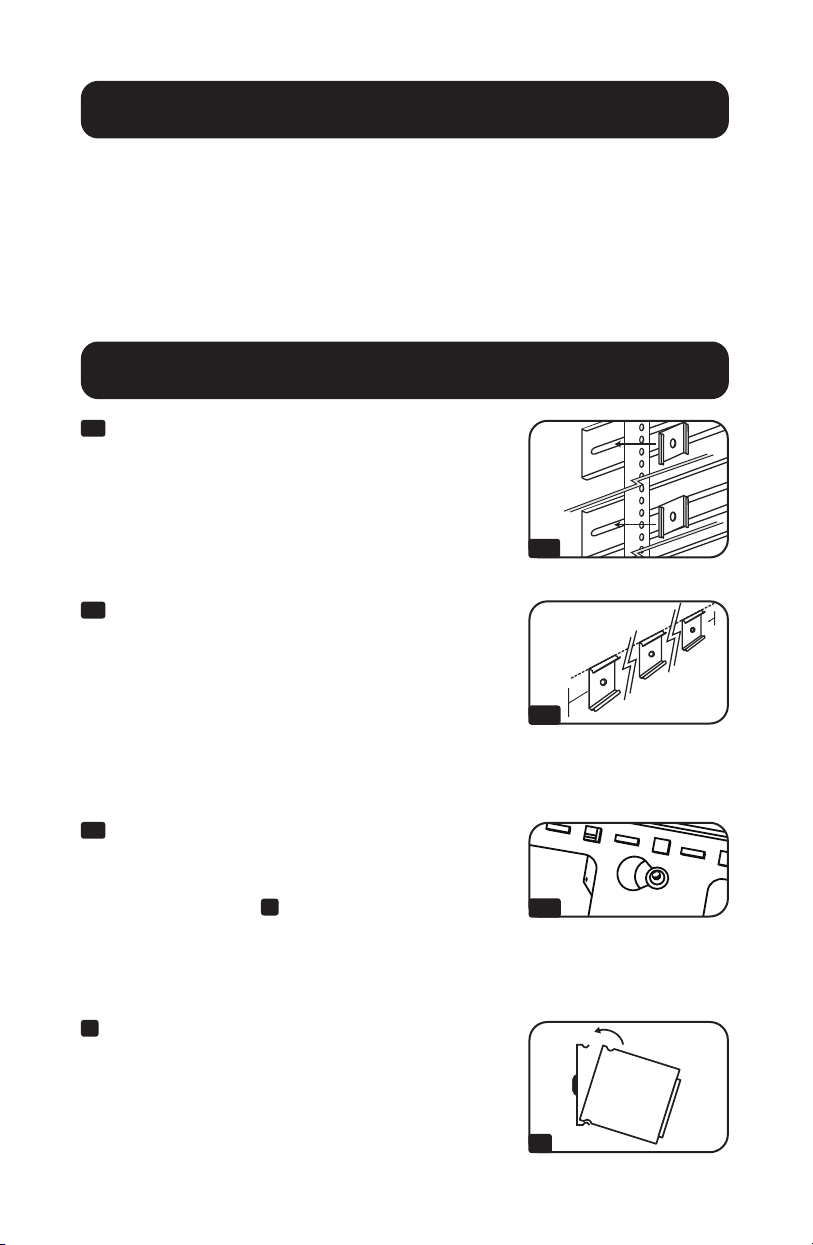
1A
0U Rack Configuration. Attach the three mounting
clips supplied with the PDU to the rack enclosure
using the included hardware. The mounting clips
should be attached along a vertical plane at
equidistant points which roughly correspond to the
center and ends of the PDU. The exact mounting
configuration may vary depending on the rack and
enclosure. If possible, use pre-existing mounting
points within the enclosure.
1B
Wall or Under-Counter Configuration. Attach the
three mounting clips supplied with the PDU to a wall
or similar flat, secure surface using the included
hardware. The mounting clips should be attached
along a vertical or horizontal plane at equidistant
points which roughly correspond to the center and
ends of the PDU. If possible, use pre-existing
mounting points. WARNING: Do not attempt to
mount the PDU with the outlets facing downward;
the mounting clips are not designed to support
the weight of the PDU in that manner.
1C
0U Rack Configuration. Attach the included
mounting buttons to the PDU. Position the PDU as
desired in the rack enclosure, align the buttons with
the rack mounting slots, and slide the PDU into
position. Go to step
3
.
Note: Regardless of configuration, the user must determine
the fitness of hardware and procedures before mounting. The
PDU and included hardware are designed for common rack
and rack enclosure types and may not be appropriate for all
applications.
2
Attach the PDU to the mounting clips. Using an
assistant, place a rear corner of the PDU at an inside
edge of the mounting clips, pivot the PDU toward the
alternate inside edge and snap into place.
2
1B
1A
1C
Loading ...
Loading ...
Loading ...