Loading ...
Loading ...
Loading ...
23
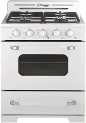
6. Replace the cap back on the regulator
7. Next you will remove the grates, burners and burner
caps from the range to access the orifices.
8. You will need a 7 mm wrench to remove the orifices.
Each orifice can be accessed easily - the larger
burner orifice is located on the burner wall.
9. Remove all LPG orifices: place in the bag and store in
a safe place.
10. Take the NG orifices provided and install them as shown below
See below for rating of orifice for each model
Smallest Medium x 2 Largest Oven
NG 0.80 mm 1.36 mm 1.51 mm 1.88 mm
11. Once all the orifices are installed, replace all burners and burner caps, then fire up
the burners to check the minimum flame height.
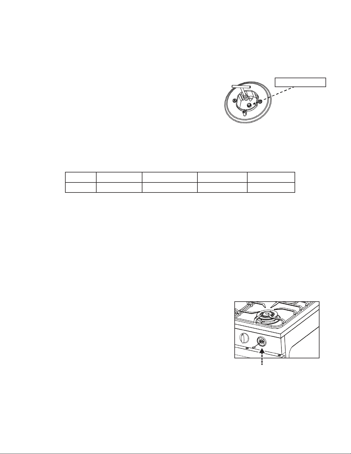
12. Minimum flame height should be approx. ¼” tall. There is a small adjustment screw
located on the valve itself. The lid and the front control panel must be removed to
accomplish this adjustment.
13. Turn the valve fully counter clockwise. Then proceed to adjust the adjustment screw
counter clockwise for a smaller flame and clockwise for a larger flame. Adjustment:
Minimum flame should be approx. ¼” tall.
14. Temporarily replace the lid, burners, burner caps and grates and recheck the flame.
Once complete, reassemble the control panel and the lid.
15. Next, the oven orifice needs to be replaced.
16. Remove all racks, then the bottom pan by lifting up
the back first to release the front then pull pan out.
17. Locate the burner tube and locate the retaining screw
at the front of the tube. Once this screw has been
removed, lift up the burner and pull away slightly to
the right to expose the oven orifice.
GAS RANGE CONVERSION (continued)
BURNER ORIFICE
FLAME HEIGHT ADJUSTMENT
Adjustment location is inside the
valve stem
ORIFICE LOCATION
Loading ...
Loading ...
Loading ...