
July 2013, Rev. 2, 12/22
© 2013-2022 Fluke Corporation. All rights reserved. Specifications are subject to change without notice.
All product names are trademarks of their respective companies.
101
Digital Multimeter
Users Manual

LIMITED WARRANTY AND LIMITATION OF LIABILITY
This Fluke product will be free from defects in material and workmanship for one year from
the date of purchase. This warranty does not cover fuses, disposable batteries, or damage
from accident, neglect, misuse, alteration, contamination, or abnormal conditions of operation
or handling. Resellers are not authorized to extend any other warranty on Fluke’s behalf. To
obtain service during the warranty period, contact your nearest Fluke authorized service
center to obtain return authorization information, then send the product to that Service Center
with a description of the problem.
THIS WARRANTY IS YOUR ONLY REMEDY. NO OTHER WARRANTIES, SUCH AS
FITNESS FOR A PARTICULAR PURPOSE, ARE EXPRESSED OR IMPLIED. FLUKE IS
NOT LIABLE FOR ANY SPECIAL, INDIRECT, INCIDENTAL OR CONSEQUENTIAL
DAMAGES OR LOSSES, ARISING FROM ANY CAUSE OR THEORY. Since some states or
countries do not allow the exclusion or limitation of an implied warranty or of incidental or
consequential damages, this limitation of liability may not apply to you.
Fluke Corporation
P.O. Box 9090
Everett, WA 98206-9090
U.S.A.
Fluke Europe B.V.
P.O. Box 1186
5602 BD Eindhoven
The Netherlands
11/99

i
Table of Contents
Title Page
Introduction ................................................................................................................. 1
Contact Fluke ............................................................................................................. 1
Safety Information ...................................................................................................... 2
Instrument Overview................................................................................................... 3
Terminals ................................................................................................................ 3
Display .................................................................................................................... 4
Rotary Switch ......................................................................................................... 6
Auto Power Off ........................................................................................................... 7
Measurements ............................................................................................................ 8
Data Hold ............................................................................................................... 8
Measure AC and DC Voltage ................................................................................. 8
Measure Resistance ............................................................................................... 10
Test for Continuity .................................................................................................. 10
Test Diodes ............................................................................................................ 12
Measure Capacitance ............................................................................................ 12

101
Users Manual
ii
Measure Frequency and Duty Cycle ...................................................................... 14
Maintenance ............................................................................................................... 16
General Maintenance ............................................................................................. 16
Replace Batteries ................................................................................................... 17
Service and Parts ....................................................................................................... 18
General Specifications ............................................................................................... 18
Accuracy Specifications ............................................................................................. 20

1
Introduction
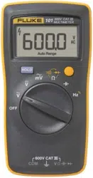
The Fluke 101 Multimeter (the Product) is a 6000-count instrument. The Product is battery
powered with a digital display.
Contact Fluke
Fluke Corporation operates worldwide. For local contact information, go to our website:
www.fluke.com
To register your product, view, print, or download the latest manual or manual supplement, go
to our website.
Fluke Corporation
P.O. Box 9090
Everett, WA 98206-9090
+1-425-446-5500

101
Users Manual
2
Safety Information
The Fluke 101 is rated to IEC 61010-1 CAT III 600 V measurement category. See General
Specifications.
A Warning identifies conditions and procedures that are dangerous to the user. A Caution
identifies conditions and procedures that could cause damage to the Product or the
equipment under test.
General Safety Information in the printed Safety Information document that ships with the
Product. It can also be found online at www.fluke.com. More specific safety information is
listed in this manual where applicable.
Digital Multimeter
Instrument Overview
3
Instrument Overview
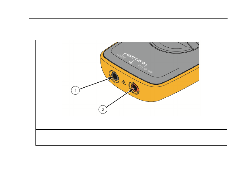
Terminals
hkm01.tif
Item Description
A Common (return) terminal for all measurements.
B Input terminal for all measurements.
101
Users Manual
4
Display
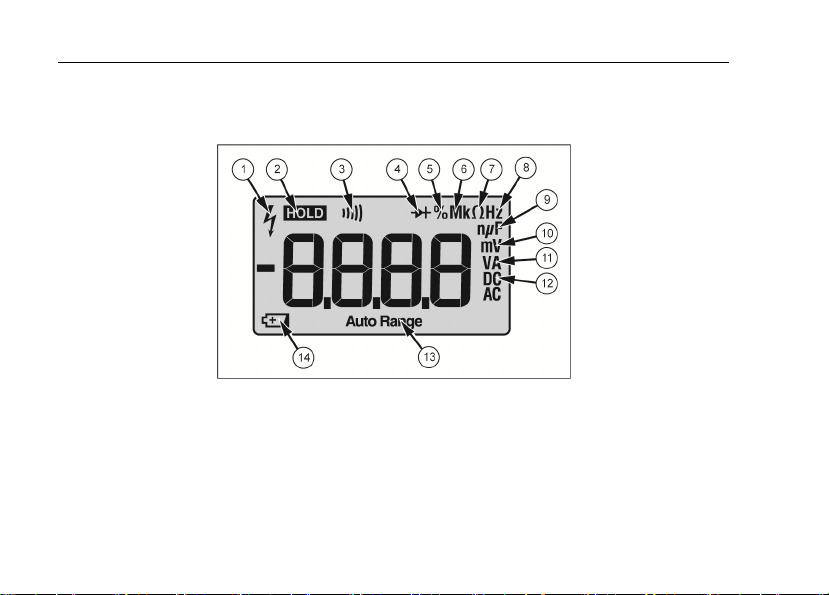
Figure 1 and Table 1 show the items on the Product display.
hkm02.tif
Figure 1. Display

Digital Multimeter
Instrument Overview
5
Table 1. Display
Item Description Item Description
A High voltage H Frequency is selected
B Display Hold is enabled I Farads
C Continuity selected J Millivolts
D Diode test is selected K Amps or volts
E Duty Cycle is selected L Dc or ac voltage or current
F Decimal prefix M Auto Range mode is enabled
G Ohms is selected N Battery is low and should be changed
101
Users Manual
6
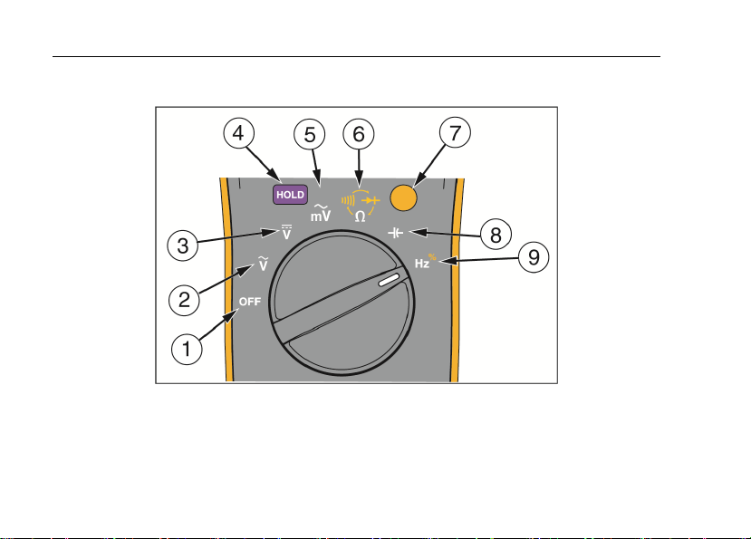
Rotary Switch
hkm06.tif
Figure 2. Rotary Switch

Digital Multimeter
Auto Power Off
7
Table 2. Rotary Switch Functions
Number Description Number Description
A Power down the Product.
F
Ohms. Push shift for continuity and
diode test.
B AC Volts G Shift. Push for yellow functions.
C DC Volts H Capacitance
D Freeze the display.
I Frequency. Push shift for duty cycle.
E AC millivolts
Auto Power Off
The Product automatically powers off after 20 minutes of inactivity.
To restart the Product, turn the rotary switch back to the OFF position and then to a
necessary position.
To disable the Auto Power Off function, hold down the YELLOW button when turning on the
Product, until PoFFshows on the display.

101
Users Manual
8
Measurements
Data Hold
XW Warning
To prevent possible electrical shock, fire or personal injury, do not use the HOLD
function to measure unknown potentials. When HOLD is turned on, the display
does not change when a different potential is measured.
To hold the present reading, push
H. Push H again to resume normal operation.
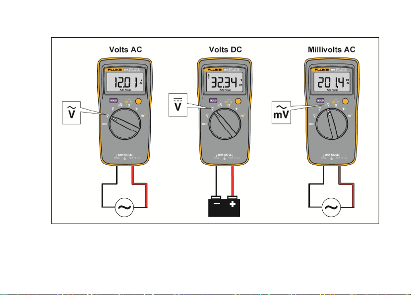
Measure AC and DC Voltage
To measure ac and dc voltage:
1. Choose ac or dc by turning the rotary switch to
K
,
L,
or G.
2. Connect the red test lead to the J terminal and the black test lead to the COM
terminal.
3. Measure the voltage by touching the probes to the correct test points of the circuit.
4. Read the measured voltage on the display.
Digital Multimeter
Measurements
9
hkm03.tif
Figure 3. Measure AC and DC Voltage

101
Users Manual
10
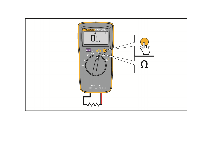
Measure Resistance
1. Turn the rotary switch to
D. Make sure power is disconnected from the circuit to be
measured.
2. Connect the red test lead to the J terminal and the black test lead to the COM
terminal.
3. Measure the resistance by touching the probes to the desired test points of the circuit.
4. Read the measured resistance on the display.
Test for Continuity
With the resistance mode selected, push the YELLOW button once to activate the continuity
mode. If the resistance is <70 Ω, the beeper sounds continuously, designating a short circuit.
If the Product reads
o
, the circuit is open.
Digital Multimeter
Measurements
11
hkm05.tif
Figure 4. Measure Resistance/Continuity

101
Users Manual
12
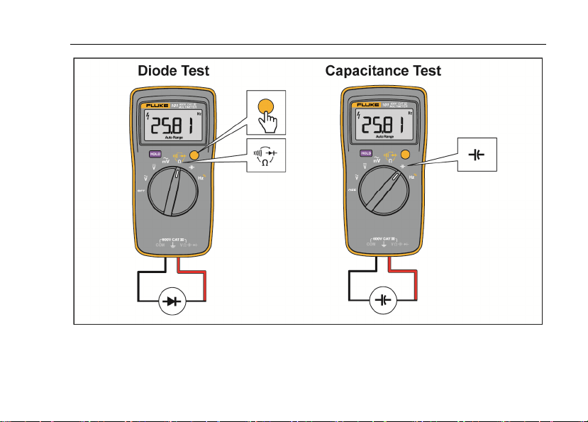
Test Diodes
1. Turn the rotary switch to
D.
2. Push the YELLOW button twice to activate the diode test mode.
3. Connect the red test lead to the J terminal and the black test lead to the COM
terminal.
4. Connect the red probe to the anode and the black test lead to the cathode of the diode
being tested.
5. Read the forward bias voltage value on the display.
6. If the polarity of the test leads is reversed with diode polarity, the display reading shows
o. This can be used to distinguish the anode and cathode sides of a diode.
Measure Capacitance
1. Turn the rotary switch to
c.
2. Connect the red test lead to the J terminal and the black test lead to the COM
terminal.
3. Touch the probes to the capacitor leads.
4. Let the reading stabilize (up to 18 seconds).
5. Read the capacitance value on the display.
Digital Multimeter
Measurements
13
hkm08.tif
Figure 5. Diode and Capacitance Tests

101
Users Manual
14
Measure Frequency and Duty Cycle
To measure frequency:
1. Turn the rotary switch to
I
.
2. Connect the red test lead to the J terminal and the black test lead to COM
terminal.
3. Measure frequency by touching the probes to the correct test points of the circuit.
4. Read the frequency on the display.
To measure duty cycle:
1. Turn the rotary switch to
I
.
2. Push the YELLOW button to switch to the duty cycle function.
3. Connect the red test lead to the J terminal and the black test lead to COM
terminal.
4. Measure duty cycle by touching the probes to the correct test points of the circuit.
5. Read the percent of duty cycle on the display.

Digital Multimeter
Measurements
15
hkm04.tif
Figure 6. Measure Frequency/Duty Cycle

101
Users Manual
16
Maintenance
Beyond replacing batteries, do not attempt to repair or service the Product unless you are
qualified to do so and have the relevant calibration, performance test, and service
instructions. The recommended calibration cycle is 12 months.
XW Warning
To prevent possible electrical shock, fire, or personal injury:
• Remove the input signals before you clean the Product.
• Use only specified replacement parts.
• Have an approved technician repair the Product.
For safe operation and maintenance of the Product, repair the Product before use
if the batteries leak.
General Maintenance
Periodically wipe the case with a damp cloth and mild detergent. Do not use abrasives or
solvents. Dirt or moisture in the terminals can affect readings.
Digital Multimeter
Maintenance
17
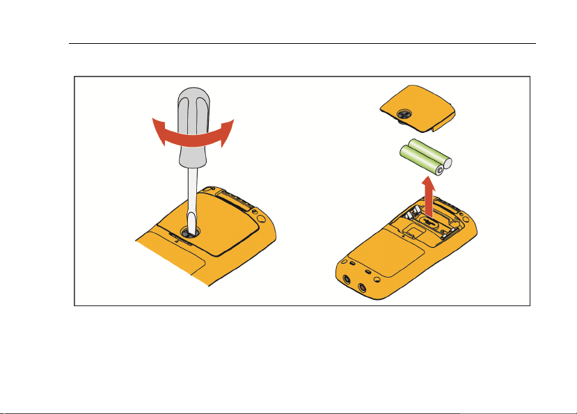
Replace Batteries
hkm07.tif
Figure 7. Replace Batteries

101
Users Manual
18
Service and Parts
If the Product fails, first check the batteries. Then, review this manual to make sure you are
operating the Product correctly.
Replacement parts are:
Item Fluke Part Number
Batteries 2838018
Battery door 4319659
Test leads TL175 4306653
Screws 4320657
General Specifications
Maximum voltage between any terminal
and Earth Ground .............................................. 600 V
Display (LCD) ..................................................... 6000 counts, update rate 3/sec
Battery Type ....................................................... 2 AAA, IEC LR03
Battery Life ......................................................... 200 hours minimum
Temperature
Operating ........................................................ 0 °C to 40 °C
Storage ........................................................... -30 °C to 60 °C
Relative Humidity
Operating Humidity ......................................... Non-condensing when <10 °C;
≤90 % at 10 °C to 30 °C;
≤75 % at 30 °C to 40 °C (Non-condensing)
Operating Humidity, 40 MΩ Range ................. ≤80 % at 10 °C to 30 °C;
≤70 % at 30 °C to 40 °C (Non-condensing)

Digital Multimeter
General Specifications
19
Altitude
Operating ........................................................ 2000 m
Storage ........................................................... 12,000 m
Temperature Coefficient ................................... 0.1 X (specified accuracy) / °C (<18 °C or >28 °C)
Size (HxWxL) ..................................................... 130 mm x 65 mm x 27 mm
Weight ................................................................ 160 g
IP Rating ............................................................. IEC 60529: IP 40
Safety ................................................................. IEC 61010-1: Pollution Degree 2,
IEC 61010-2-033: CAT III 600 V
Electromagnetic Compatibility (EMC)
International .................................................... IEC 61326-1: Portable, IEC 61326-2-2
CISPR 11: Group 1, Class A
Group 1: Equipment has intentionally generated and/or uses conductively-coupled radio frequency
energy that is necessary for the internal function of the equipment itself.
Class A: Equipment is suitable for use in all establishments other than domestic and those directly
connected to a low-voltage power supply network that supplies buildings used for domestic purposes.
There may be potential difficulties in ensuring electromagnetic compatibility in other environments
due to conducted and radiated disturbances.
Emissions that exceed the levels required by CISPR 11 can occur when the equipment is connected
to a test object. The equipment may not meet the immunity requirements of this standard when test
leads and/or test probes are connected.
Korea (KCC) ................................................... Class A Equipment (Industrial Broadcasting &
Communication Equipment)
Class A: Equipment meets requirements for industrial electromagnetic wave equipment and the seller
or user should take notice of it. This equipment is intended for use in business environments and not
to be used in homes.
USA (FCC) ..................................................... 47 CFR 15 subpart B. This product is considered an
exempt device per clause 15.103.

101
Users Manual
20
Accuracy Specifications
Accuracy is specified for 1 year after calibration, at operating temperature range of 18 °C to
28 °C, relative humidity at 0 % to 90 %. Accuracy specifications take the form of: ±([% of
Reading] + [Number of Least Significant Digits])
Function Range Resolution Accuracy
AC Volts
(40 Hz to 500 Hz)
[1]
v
6.000 V
60.00 V
600.0 V
0.001 V
0.01 V
0.1 V
1.0 % + 3
DC Volts
V
6.000 V
60.00 V
600.0 V
0.001 V
0.01 V
0.1 V
0.5 % + 3
AC Millivolts
(40 Hz to 500 Hz)
[1]
u
600.0 mV 0.1 mV 3.0 % + 3
Diode Test
[2]
G
2.000 V 0.001 V 10 %
[1] All AC, Hz, and duty cycle are specified from 1 % to 100 % of range. Inputs below 1 % of range are not specified.
[2] Typically, open circuit test voltage is 2.0 V and short circuit current is <0.6 mA.

Digital Multimeter
Accuracy Specifications
21
Function
Overload
Protection
Input Impedance
(Nominal)
Common Mode
Rejection Ratio
Normal Mode
Rejection Ratio
AC Volts 600 V
[1]
>10 MΩ <100 pF
>60 dB at dc,
50 Hz or 60 Hz
_
AC Millivolts 600 mV >1 M, <100 pF
>80 dB at dc,
50 Hz or 60 Hz
_
DC Volts 600 V
[1]
>10 MΩ <100 pF
>100 dB at
50 Hz or 60 Hz
>60 dB at
50 Hz or 60 Hz
[1] 6 x 10
5
V Hz Max.

101
Users Manual
22
Function Range Resolution Accuracy
Resistance
O
400.0 Ω
4.000 kΩ
40.00 kΩ
400.0 kΩ
4.000 MΩ
40.00 MΩ
0.1 Ω
0.001 kΩ
0.01 kΩ
0.1 kΩ
0.001 MΩ
0.01 MΩ
0.5 % + 3
0.5 % + 2
0.5 % + 2
0.5 % + 2
0.5 % + 2
1.5 % + 3
Capacitance
[1]
c
50.00 nF
500.0 nF
5.000 μF
50.00 μF
500.0 μF
1000 μF
0.01 nF
0.1 nF
0.001 μF
0.01 μF
0.1 μF
1 μF
2 % + 5
2 % + 5
5 % + 5
5 % + 5
5 % + 5
5 % + 5
Frequency
[2]
Hz
(10 Hz – 100 kHz)
50.00 Hz
500.0 Hz
5.000 kHz
50.00 kHz
100.0 kHz
0.01 Hz
0.1 Hz
0.001 kHz
0.01 kHz
0.1 kHz
0.1 % + 3
Duty Cycle
[2]
1 % to 99 % 0.1 % 1 % typical
[3]
[1] Specifications do not include errors due to test lead capacitance and capacitance floor (may be up to 1.5 nF in the
50 nF range).
[2] All AC, Hz, and duty cycle are specified from 1 % to 100 % of range. Inputs below 1 % of range are not specified.
[3] Typical means when the frequency is at 50 Hz or 60 Hz and the duty cycle is between 10 % and 90 %.