UN Series Models
Installation Manual
* This manual contains the precautions that must be followed by the professionals in charge of the installation.
Please be sure to read Setup manual and User’s Manual.
NEC Display Solutions, Ltd.
2020/02/13
Ver. 2.0

English - 2
Table of contents
1. Precautions when unpacking ..................................................................................................................3
2. Performances check before installation ................................................................................................. 5
3. Precautions when installing and moving the product .......................................................................... 6
4. Display external dimensions tolerances .................................................................................................9
5. Allowable temperature and installation environment ....................................................................... 10
6. Wall mount brackets installation .......................................................................................................... 11
7. Display cushions ...................................................................................................................................... 14
8. How to remove the protective tape ....................................................................................................... 15
9. Multiple screens installation .................................................................................................................. 17
10. Pins, spacers and spacer sheets ............................................................................................................. 18
11. Compatibility of optional products .......................................................................................................22
12. Installation procedure of options .......................................................................................................... 23
13. When repacking and sending the product ........................................................................................... 24
English
English - 3
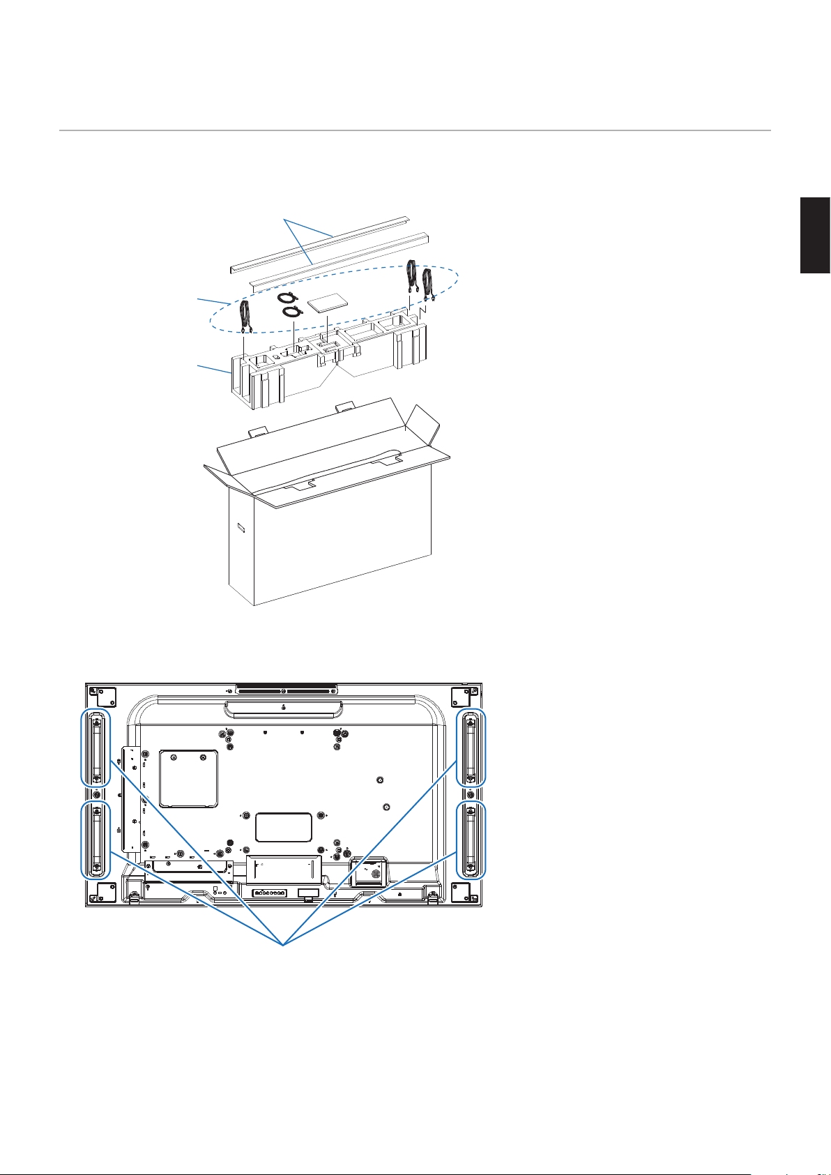
1. Precautions when unpacking
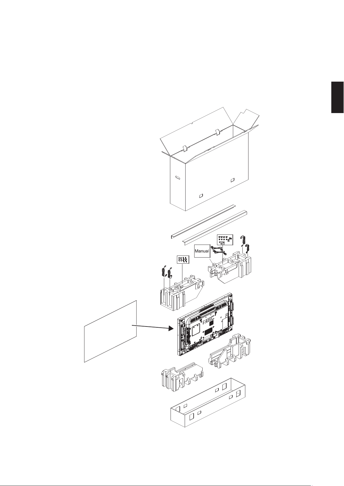
(1) Remove all the accessories from the package before removing the display.
L-shaped protections
Accessories
Cushioning materials
(2) Do not damage or dispose of the packing materials but keep them in case you need to pack the product again.
(3) Hold the display by the handle when removing it from the packing materials.
Handle
English - 4
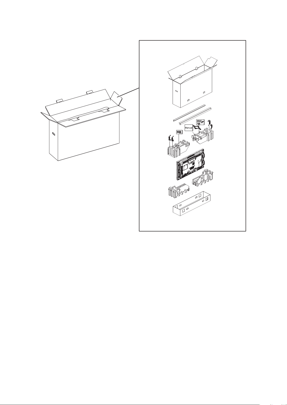
(4) When repacking the product, check the arrangement of the packing materials shown on the box.
Front side
English
English - 5
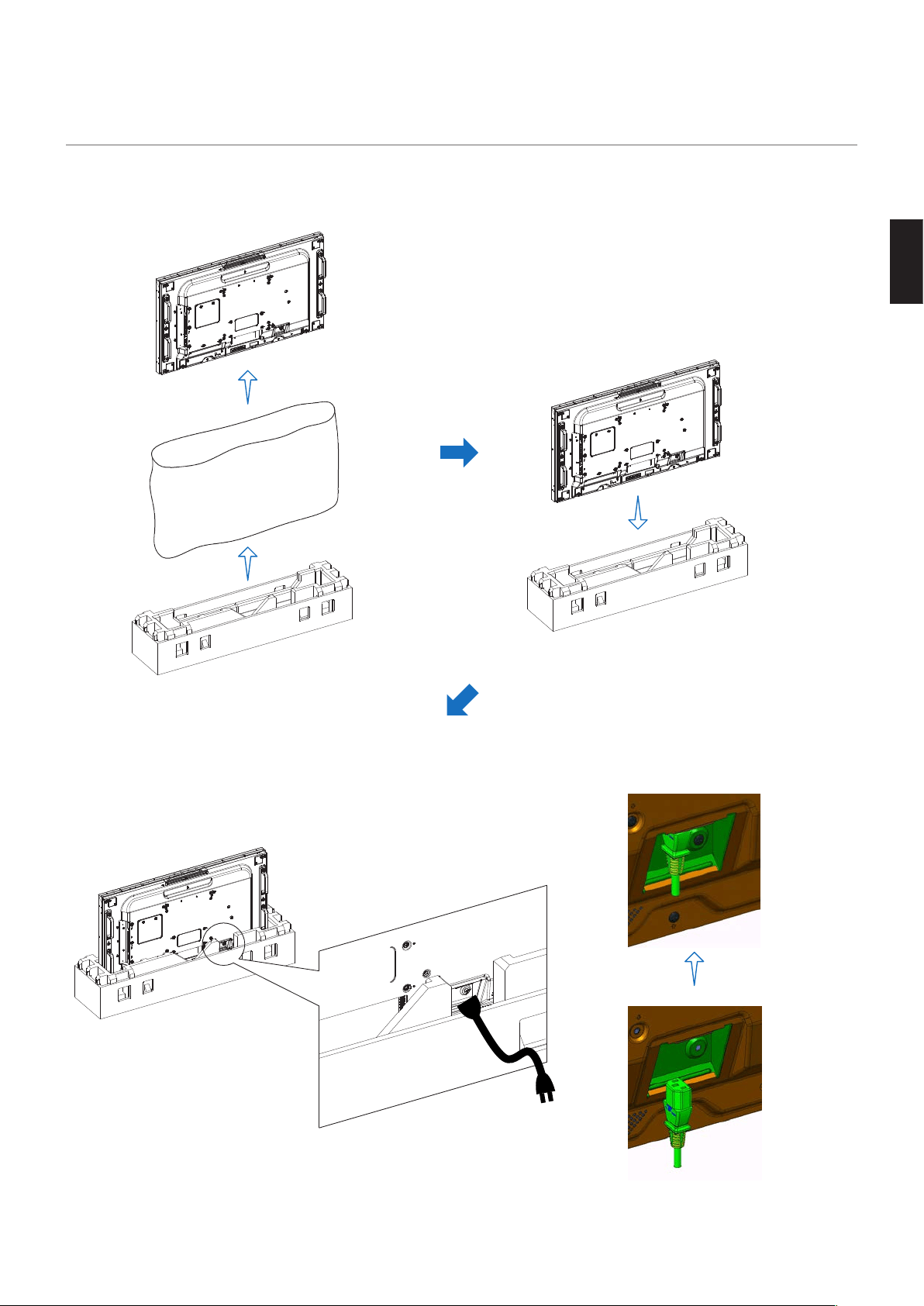
2. Performances check before installation
(3) Connect the power cord to the display, while it stands vertically in the
cushioning materials.
Do not keep the display turned on for a long time in that position.
(1) Remove the display from the cushioning
materials and from the protective bag.
(2) Put the display back in the cushioning materials.
English - 6
3. Precautions when installing and moving the
product
(1) When installing or moving the display, always keep it in the standing position, do not put it on its side or upside down.
Always hold the display by the handles to move it.
(2) Do not hold the display by a part other than the handles.
(3) The display must be carried by at least 2 people.
Handle
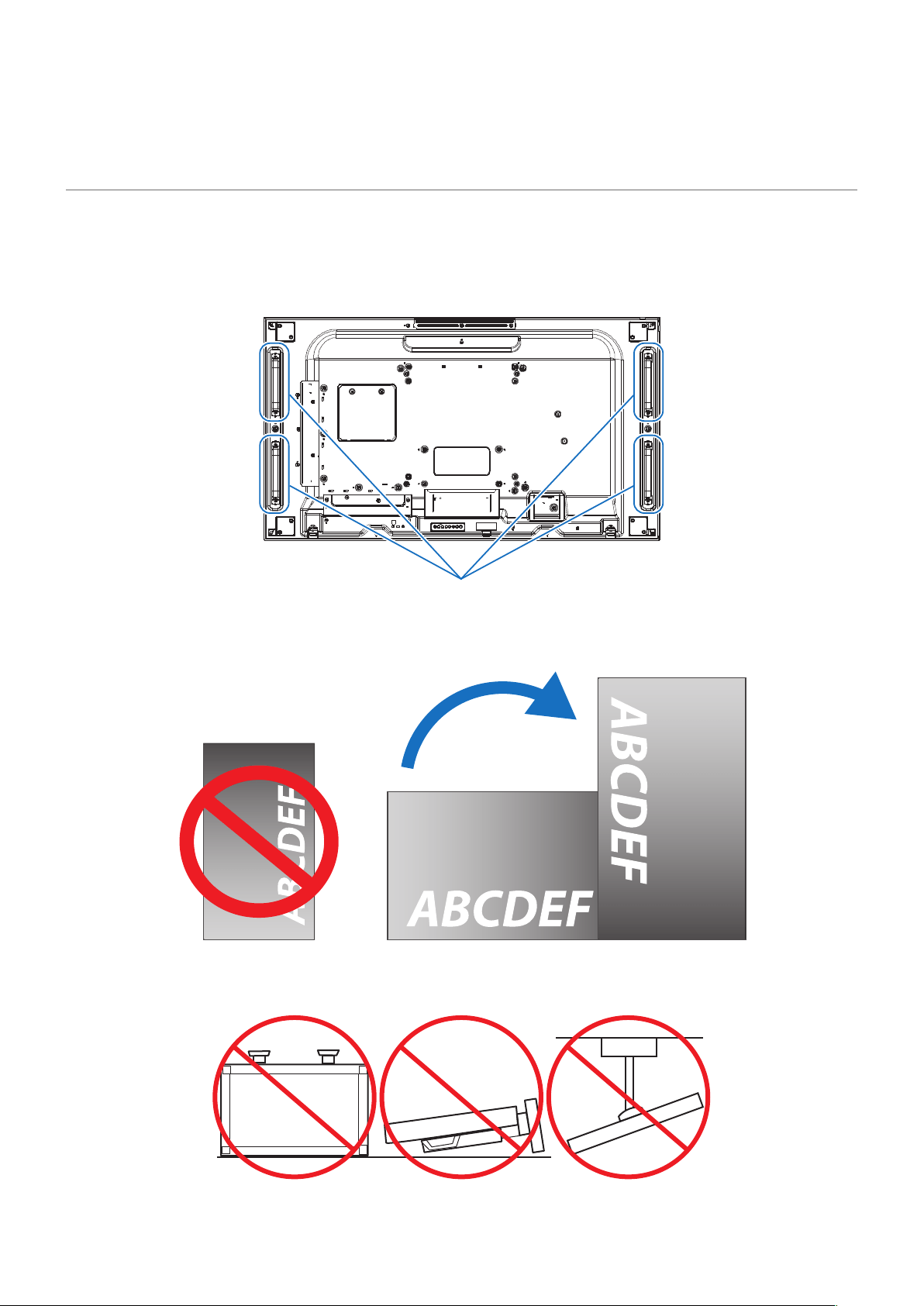
(4) When installing the display in the portrait orientation, be sure to place the left side on the top when seen from the
front.
The display cannot be installed upside down.
Do not install the display at a tilt.
Do not install it upside down, on its side, or with the screen facing downward. Otherwise, it may damage the screen.
English
English - 7
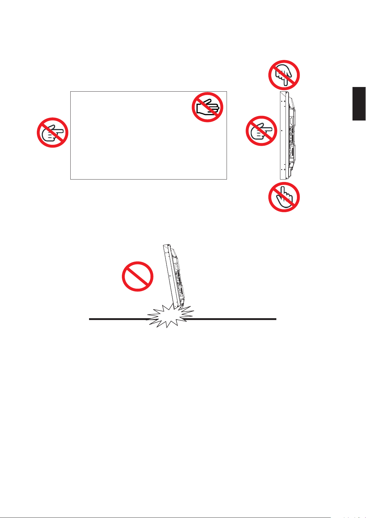
(5) Do not touch the top, bottom, left and right sides of the display. Also, do not touch the screen surface of the display.
Applying pressure or shocks on the top or left sides of the display may adversely aect the image quality.
Don’t
Don’t
Don’tDon’t
Don’t
Front side
(6) Putting the bottom of the display or the screen surface directly on the oor may damage the display.
Do not put the display directly on the oor but use the stand or the product package to keep it vertical.
Don’t
English - 8
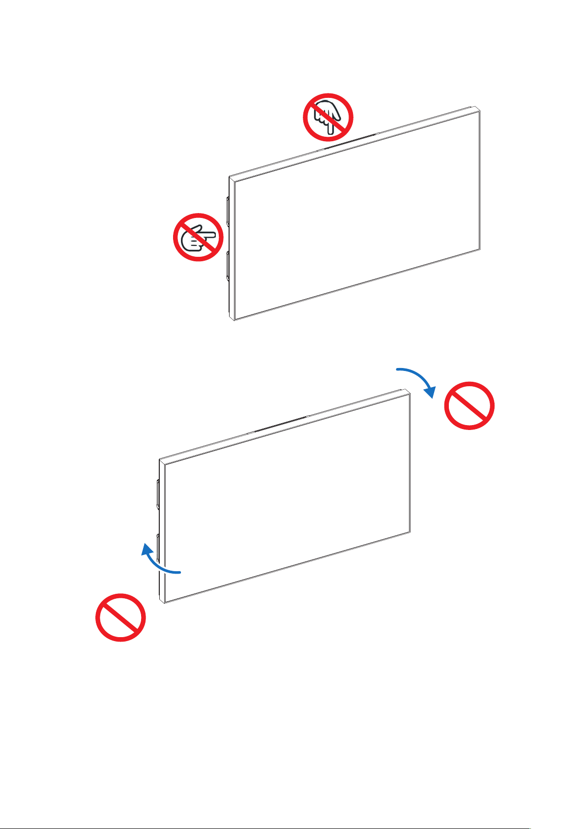
(7) When installing the display in a multiple screens conguration, do not place it in a structure that continuously
applies a load on its top or left side. Otherwise, it may adversely aect the image quality.
Don’t
Don’t
Front side
(8) Do not bend the display when installing it.
Don’t
Don’t
Front side
(9) Pay attention not to apply vibrations or shocks to the display when installing it.
Otherwise, it may cause a malfunction.
English
English - 9
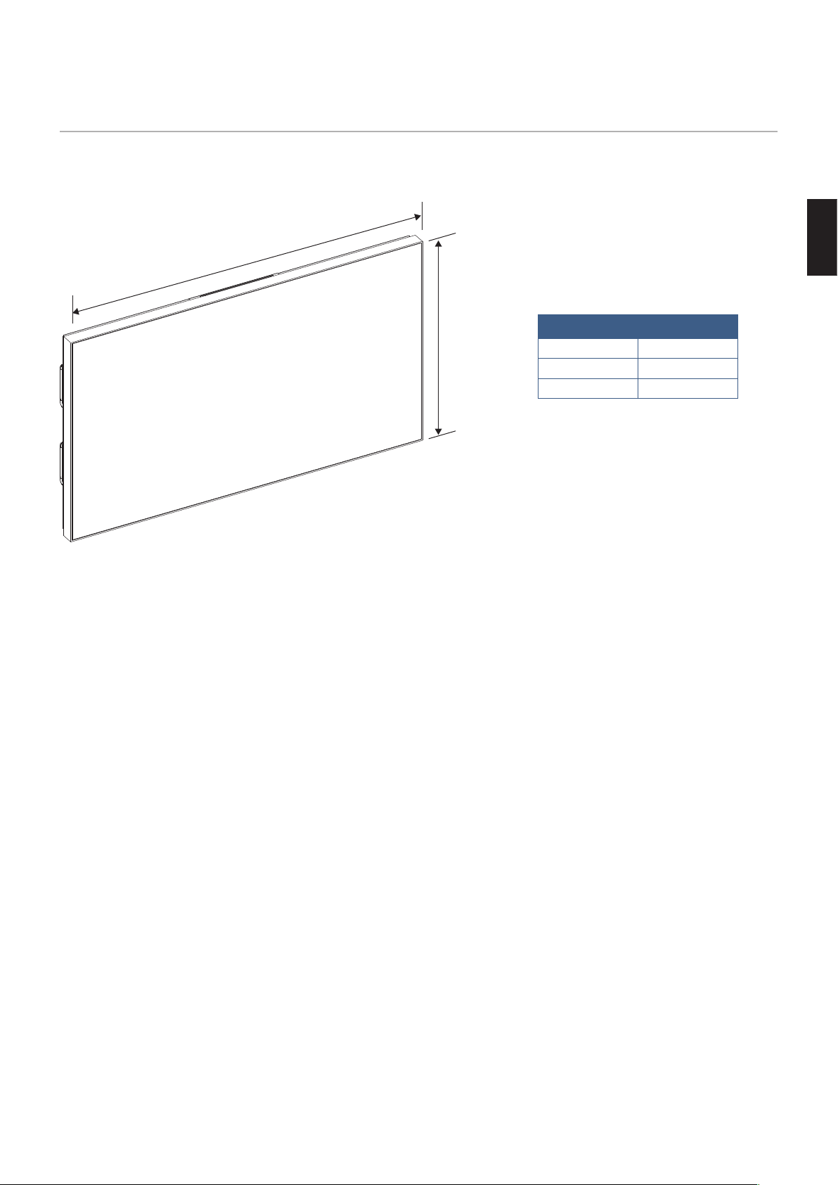
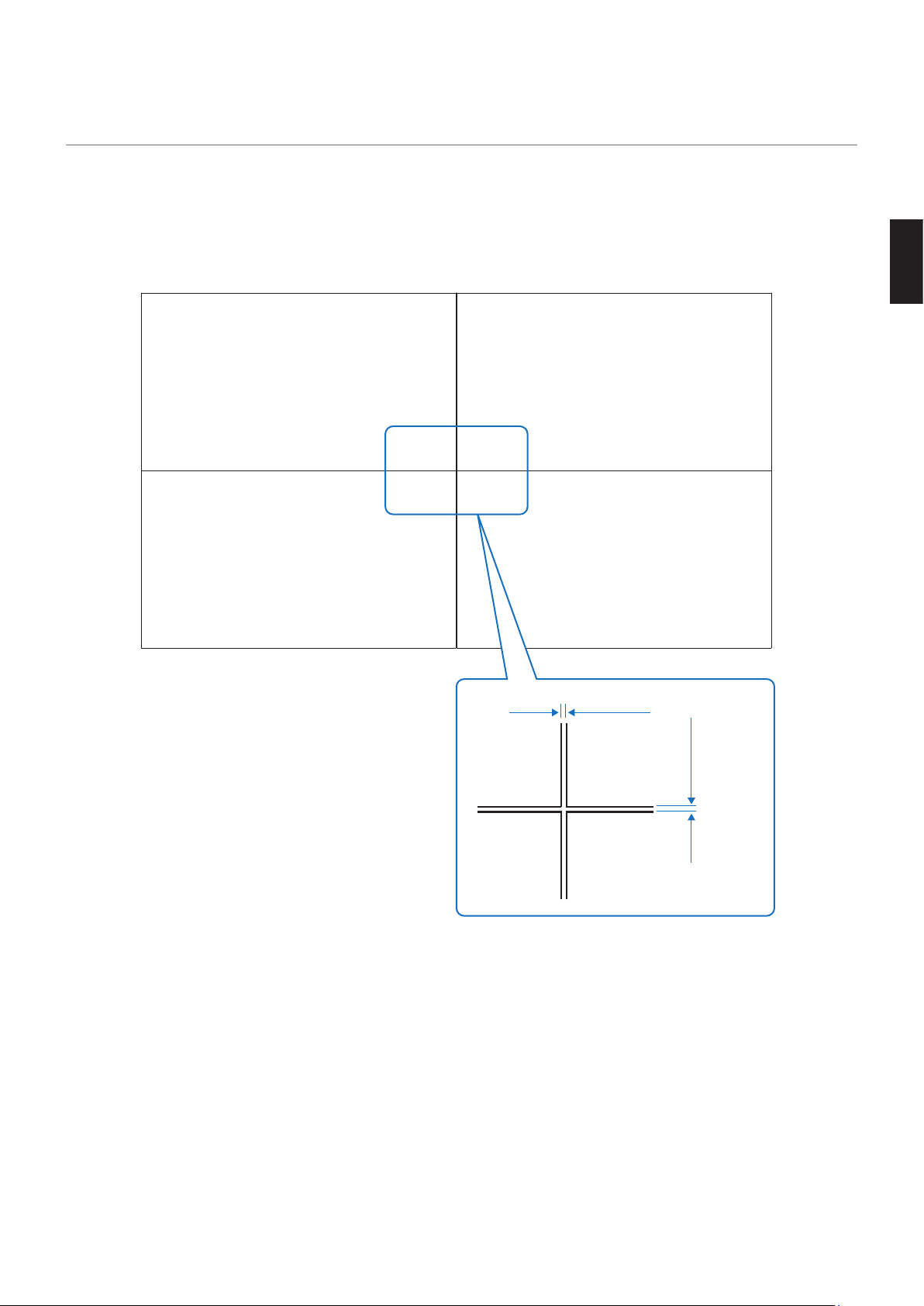
4. Display external dimensions tolerances
External dimensions tolerances of the display are as follows.
Consider these tolerances when installing the display and pay attention that it does not interfere with other parts of the
structure.
Front side
A
B
Tolerance
A B
±1.3 mm ±1.3 mm
English - 10
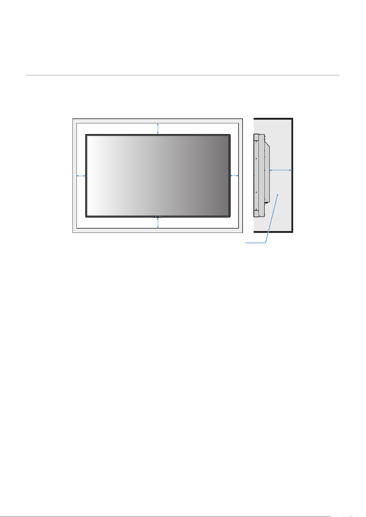
5. Allowable temperature and installation
environment
When installing the display in a narrow place (in a case embedded in a wall, etc.), leave gaps as shown in the gure below
between the display and the wall to prevent an increase in the temperature.
You may also implement suitable cooling measures.
100 mm
100 mm
30 mm
100 mm
100 mm
40°C (104°F) or less
The guaranteed ambient temperature for the display is 40°C (104°F).
When using it inside a case, take measures such as installing cooling fans in the case or air vents to keep the temperature
inside the case at a temperature of 40°C (104°F) or lower.
The display is equipped with temperature sensors and cooling fans. These fans turn on automatically when the inner
temperature is too high.
A warning is displayed in any environment that exceeds the guaranteed temperature, even when the cooling fans are
being used.
Using the display in an environment where a warning is displayed may cause a malfunction. In such a case, turn o the
main power supply.
In addition to automatic operation of the built-in cooling fans when the temperature exceeds the guaranteed temperature,
you can set the cooling fans to operate continuously under DISPLAY PROTECTION -> FAN CONTROL in the OSD menu.
When using the display with an option board, some of the cooling fans may turn on automatically to cool the option board
even when the display operates within the guaranteed temperature range.
When the display is installed inside a case or when it is used with the LCD surface covered with an acrylic sheet or other
protective sheets, check the inner temperature under DISPLAY PROTECTION -> HEAT STATUS in the OSD menu and then
congure the fan operation as required.
English
English - 11
6. Wall mount brackets installation
(1) Use only mounting brackets that comply with the VESA standards.
(2) Install the display only after thoroughly checking the strength of the mounting surface.
(3) Use mounting brackets strong enough to support the display.
(4) Check the strength and other safety factors before installing the display.
(5) Refer to the mounting brackets manual for details on the mounting method and on how to guarantee the
installation safety.
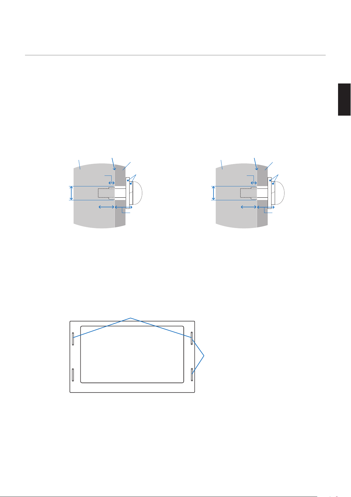
(6) When using M6 screws, make screw holes of 8.5 mm or less in diameter.
When using M8 screws, make screw holes of 10 mm or less in diameter.
(7) Pay attention not to leave any gap between the installation surface of the display and the mounting brackets.
Screw
The display
8.5 mm in
diameter or less
No gap
Washer
Mounting bracket
Non-threaded
part 4 mm
Mounting
bracket and
washer thickness
10 -12 mm
[With M6 screws]
Screw
The display
10 mm in
diameter or less
No gap
Washer
Mounting bracket
Non-threaded
part 4 mm
Mounting
bracket and
washer thickness
15-17 mm
[With M8 screws]
(8) When installing the display on a wall or the ceiling, install a fall protection wire rope for safety.
(9) Never attach the display to a wall or the ceiling using only the fall protection wire rope.
(10) Install the fall protection wire rope not fully stretched.
When attaching the fall protection wire rope to the handles, use the handles shown in the picture below
depending on the orientation.
When attaching the fall protection wire rope to the speaker brackets, follow the method shown in the gure
below.
(Tightening torque 139 to 189 N•cm)
Fall protection wire rope position with landscape orientation
Fall protection wire rope position
with portrait orientation
English - 12
(11) When attaching the wire rope to a display equipped with speakers (landscape orientation only)
Attach the wire rope using the speaker brackets.
Wire rope
Mounting bracket
Speaker
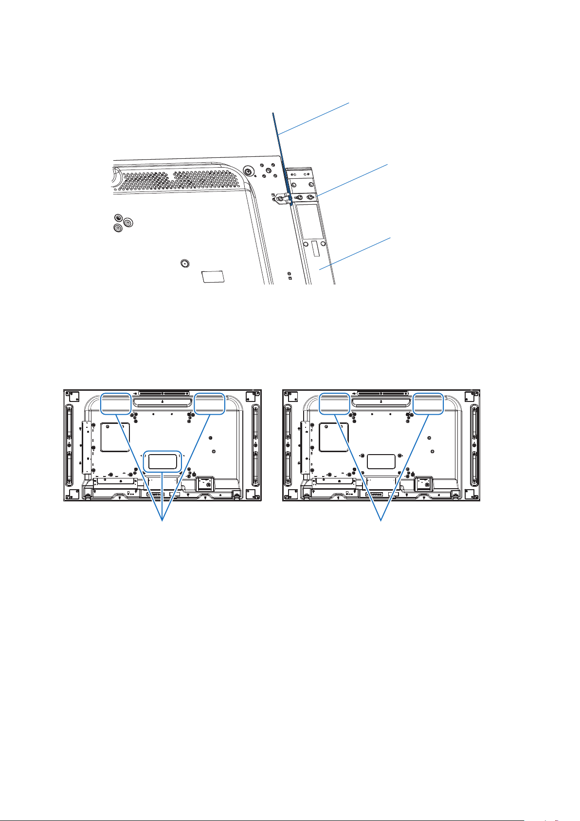
(12) The display fans are located at the three locations shown in the gure below.
Do not obstruct the fan vents with the mounting brackets or other parts.
There are 3 fan vents when the option board is used, and 2 fan vents when the option board is not used.
Using the display with the fan vents obstructed may cause a malfunction.
[When the option board is used]
Fan locations
[When the option board is not used]
Fan locations
English
English - 13
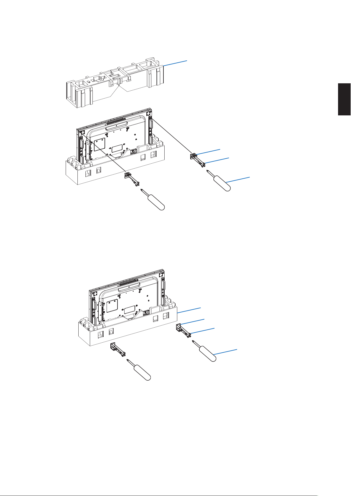
(13) When using the NEC wall mount kit, remove the upper cushioning materials and x the display top brackets to the
display using screws.
Upper cushioning materials
Display top bracket
Screw
Screwdriver
(14) It is possible to x the display bottom brackets by passing the screw through the holes in the lower cushioning
materials.
Since it is possible to x the brackets with the display maintained by the cushioning materials in the vertical
position, there is no risk to damage the screen.
Lower cushioning materials
Display bottom bracket
Screw
Screwdriver
English - 14
7. Display cushions
Some of the display models have cushions stuck around them. The cushions must be removed before installing these
models.
The cushions must be removed slowly.
Otherwise, it may damage the display.
Keep the display cushions in the event you need to pack the display again.
For models: UN492S/UN492VS/UN552S/UN552VS
Display cushion
Front side
English
English - 15
8. How to remove the protective tape
Some of the display models have protective tape stuck on their upper side to protect them from shocks during installation.
Remove the protective tape following the procedure below.
For models: UN492S/UN492VS/UN552S/UN552VS
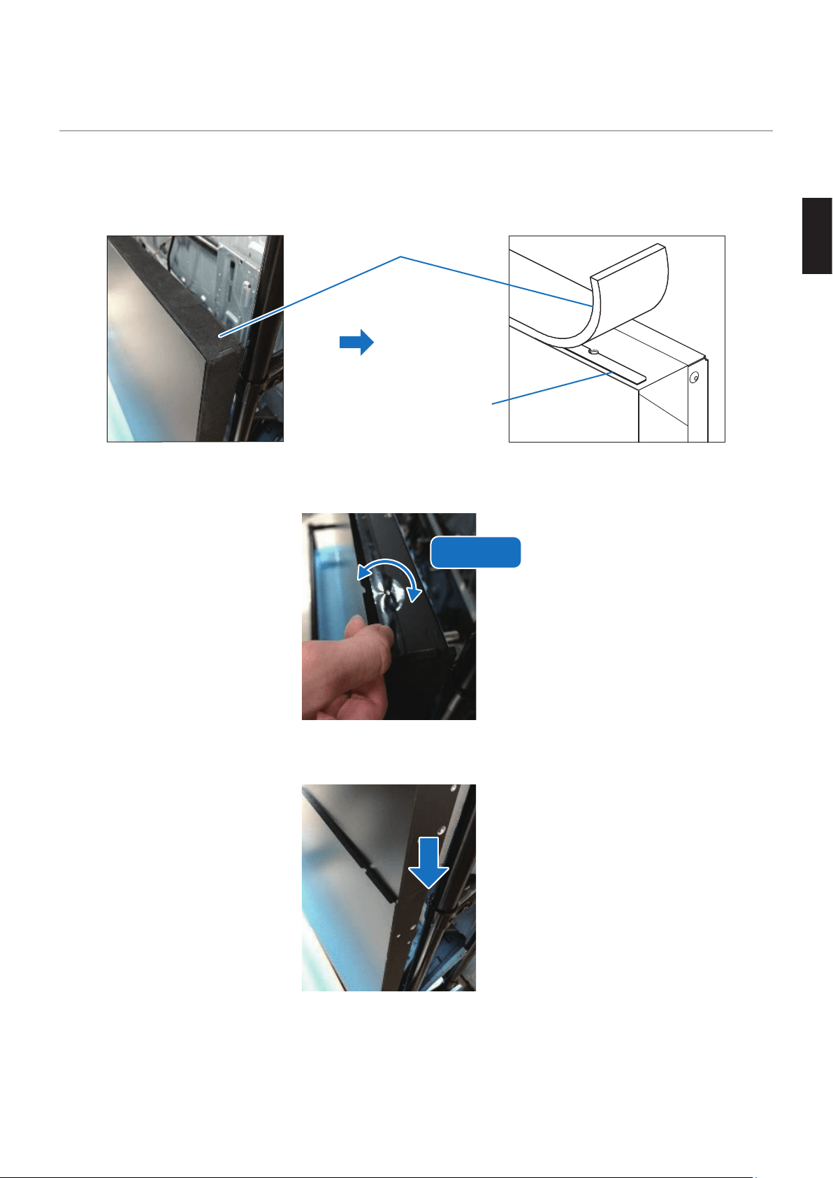
(1) Remove the display cushions.
Display cushion
Protective tape
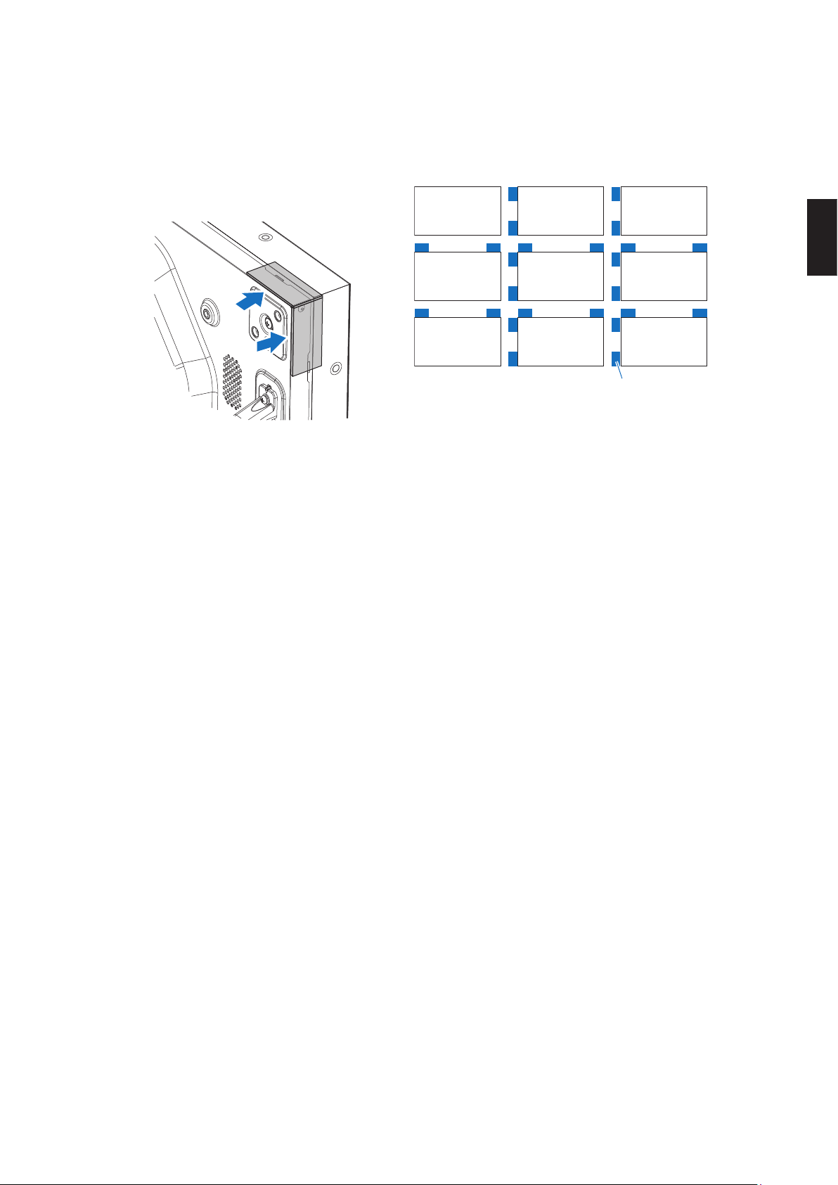
(2) Open the pieces of protective tape by turning them in the direction of the arrow before installing the display in a
multiple screens conguration.
Open
(3) Install the display that comes above.
English - 16
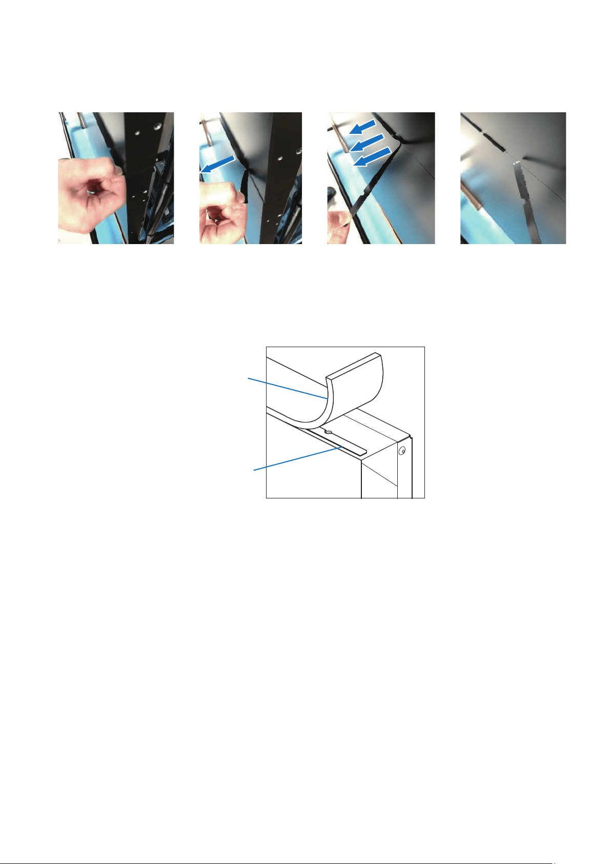
(4) After installing the display in a multiple screens conguration, hold the extremity of the piece of protective tape and
pull it in the direction of the arrow to remove it.
Remove the protective tape slowly. Otherwise, it may damage the display.
(5) Since the protective tape is very thin, it is possible to install the display in a multiple screens conguration without
removing it.
In this case, remove only the display cushions.
Display cushion
Protective tape
English
English - 17
9. Multiple screens installation
(1) When installing the displays in a multiple screens conguration, turn the displays o and leave a gap of 1.0 mm
between each display.
Note that light from the back may pass through the gaps between the displays.
To prevent the light from passing through the gaps, install a plate that stops the light at the back of the displays.
This plate is not supplied by NEC.
Gap of 1 mm
Gap of 1 mm
(2) Consider the following when installing the display in a multiple screens conguration.
(a) Check that the wall to which the mounting brackets will be installed is perfectly at.
(b) Make sure that the mounting brackets used are strong enough to meet the installation requirements.
(c) Choose a structure in which load is not applied on the display top and left sides.
(d) Pay attention that the cable route does not interfere with other parts of the structure.
(e) Choose a conguration with which there is no risk that the displays bend after they have been installed.
English - 18
10. Pins, spacers and spacer sheets
Some display models are supplied with pins, spacers and spacer sheets.
With multiple screens conguration, installing the pins and the spacers makes it possible to secure a constant gap between
the displays.
However, the pins can be installed only on the models that have pin holes of 6 mm in diameter in their bottom and right
sides. The pins cannot be used with the other models. The pins and the spacers cannot be used with installation brackets
that allow the display to move, such as pantograph or sliding mechanisms.
Pin hole
Front side
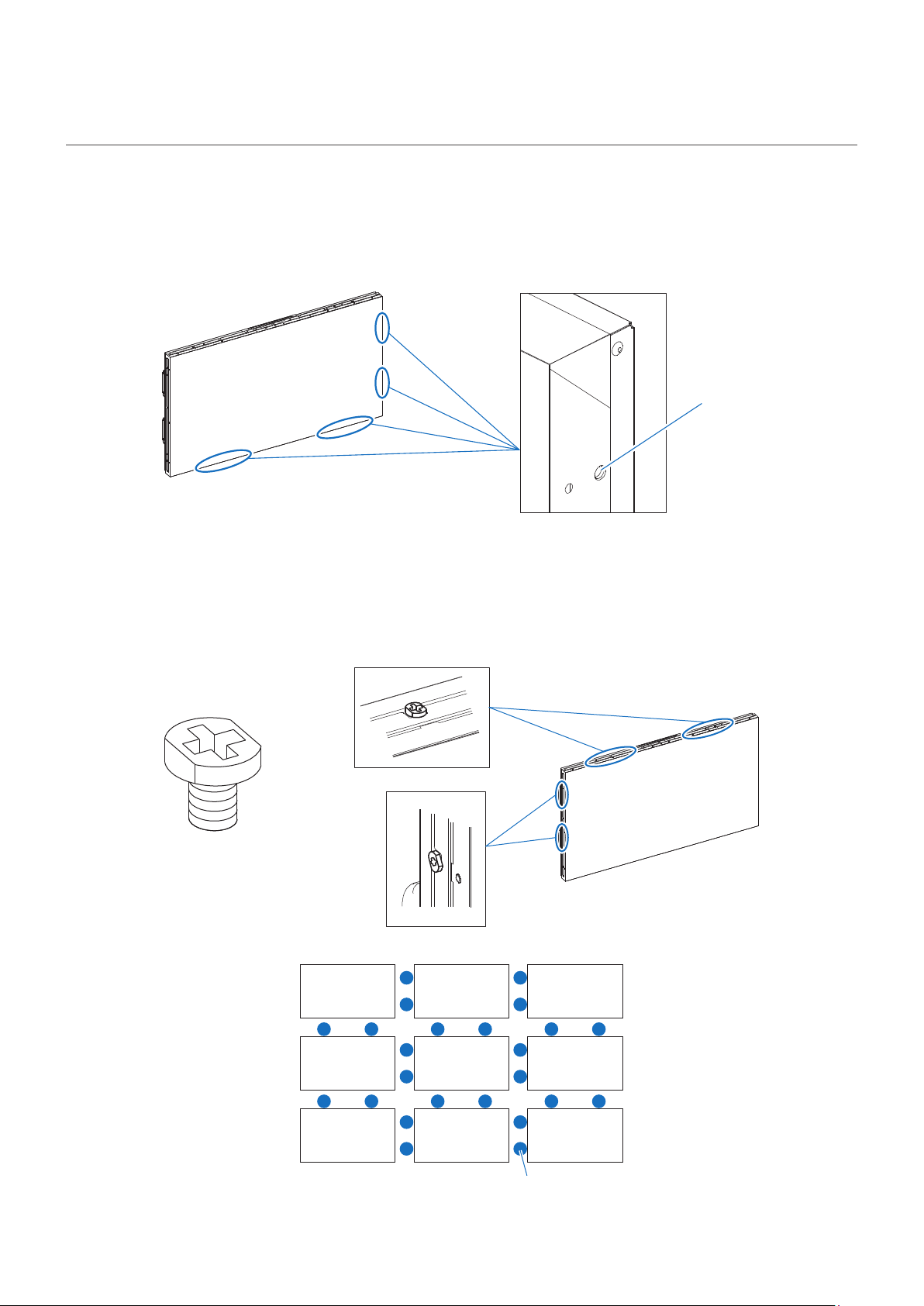
(1) Spacers
The spacers supplied with the display can be installed in the screw holes on the top and left sides of the display.
They are useful to prevent the display from coming into contact on their weaker sides with other displays in multiple
screens conguration. Therefore, we recommend installing these spacers in this conguration.
However, the spacers cannot be used with installation brackets, such as pantograph or sliding mechanisms, that
allow the display to move back and forth or right and left.
Front side
Spacer
[Installation locations]
Example: Spacer installation with multiple screens conguration
Spacer
English
English - 19
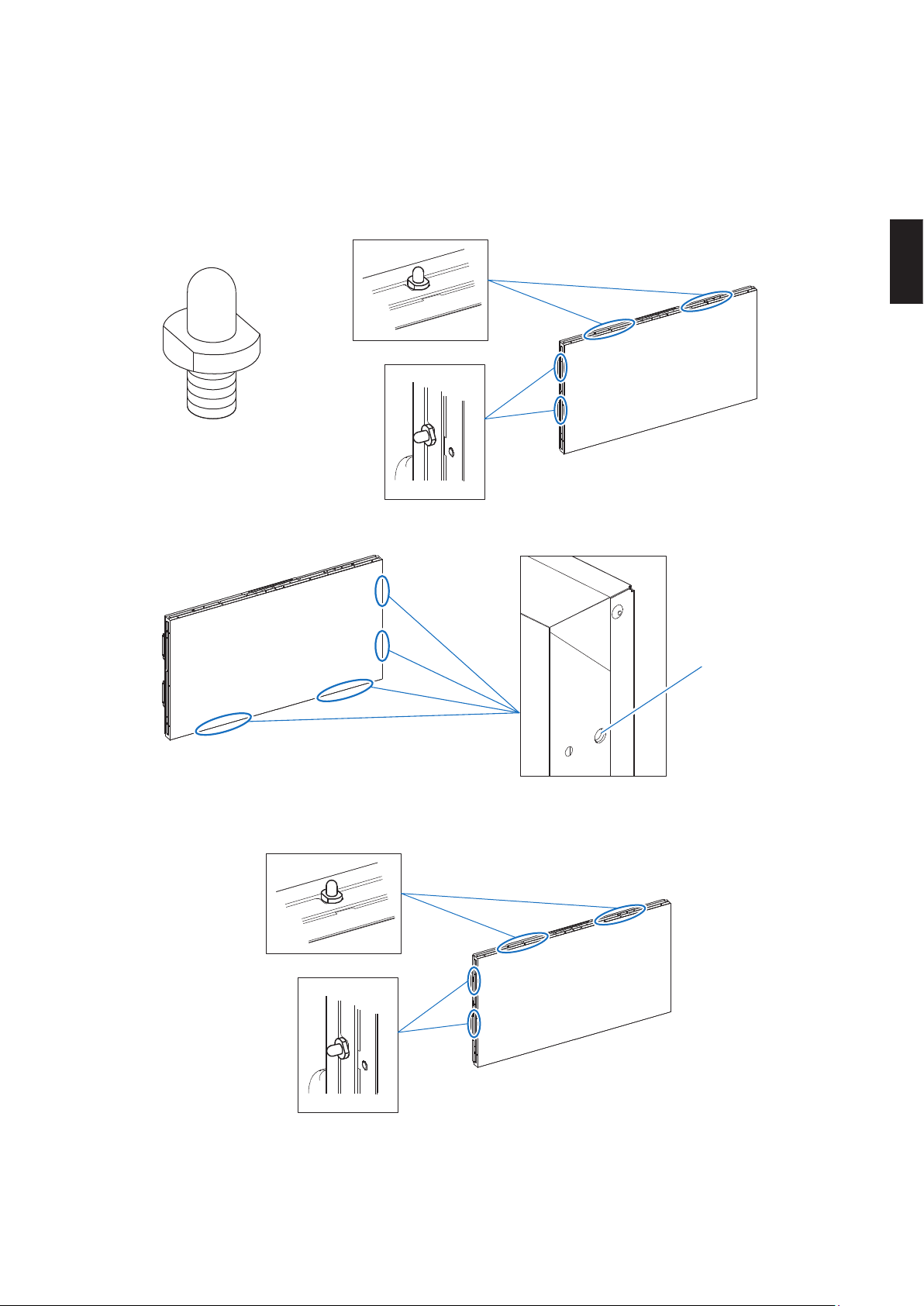
(2) Pins
The pins supplied with the display can be installed in the screw holes on the top and left sides of the display.
They are useful to prevent the display from coming into contact on their weaker sides with other displays in multiple
screens conguration. Using these pins also facilitates alignment when xing the display to VESA wall mounting
brackets.
However, the spacers cannot be used with installation brackets, such as pantograph or sliding mechanisms, that
allow the display to move back and forth or right and left.
Front side
Pin
[Installation locations]
The displays have two pin holes on each of their bottom and right sides.
Pin hole
Front side
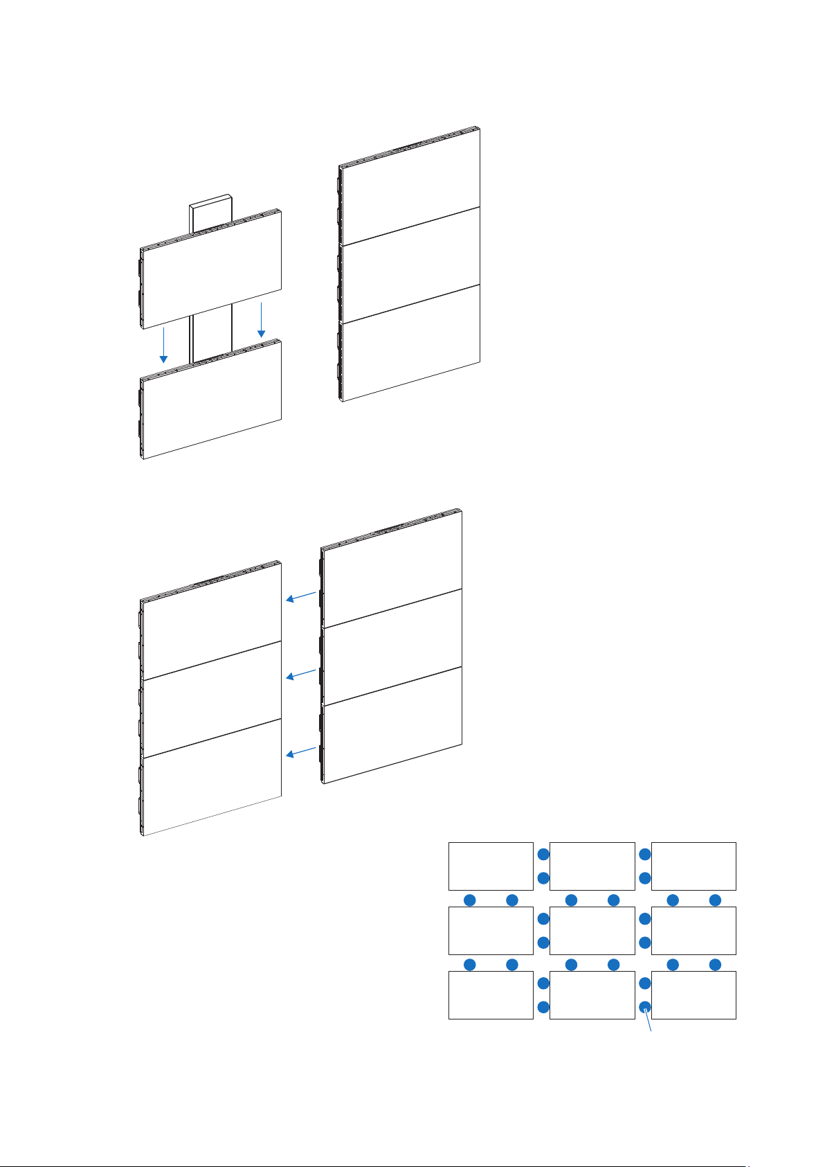
Follow the procedure below to install the pins.
(a) Fix the pins on the top and left sides on the display.
Front side
English - 20
(b) Fix the display on the VESA wall mounting bracket and insert the pins into the holes of the display placed
above.
(c) Insert the pins to the pin holes on the display sides.
Example: Spacer installation with multiple screens conguration
Spacer
English
English - 21
(3) Spacer sheets
Spacer sheets are useful to prevent the display from coming into contact on their weaker sides with other displays.
Remove the release paper from the double-sided tape on the back of the spacer sheet, and stick the spacer sheet
aligned with the edge at the back of the display.
Spacer sheet
Example: Spacer sheet installation with multiple screens conguration
* Caution: When using movable installation brackets
• If pins are installed to the display, the display cannot be moved.
• When spacers or spacer sheets are installed to the display, the spacers and the spacer sheets may contact or rub against
the display and cause image problems in the case the display is allowed to move.
• Do not install the pins, spacers or spacer sheets when using a movable bracket or an adjustable stand that allows the
display to move.
• Example of movable installation brackets are such as pantograph mechanisms, slide mechanisms.

English - 22
11. Compatibility of optional products
For information on optional mounting brackets compatibility, refer to the manual supplied with the optional mounting
brackets.

English
English - 23
12. Installation procedure of options
For information on the installation procedure of options, refer to the manual supplied with the options.
English - 24
13. When repacking and sending the product
Some of the display models have protective tape stuck on their upper side to protect them from shocks during installation.
With these models, always stick the display cushions back in place before sending the display.
Sending the display without the cushions may cause malfunctions due to vibrations during transportation.
If the cushions have been lost, fold inward the corners of the front ap of the box following the lines to pack the display.
The packing method is as follows.
1. Models with display cushion
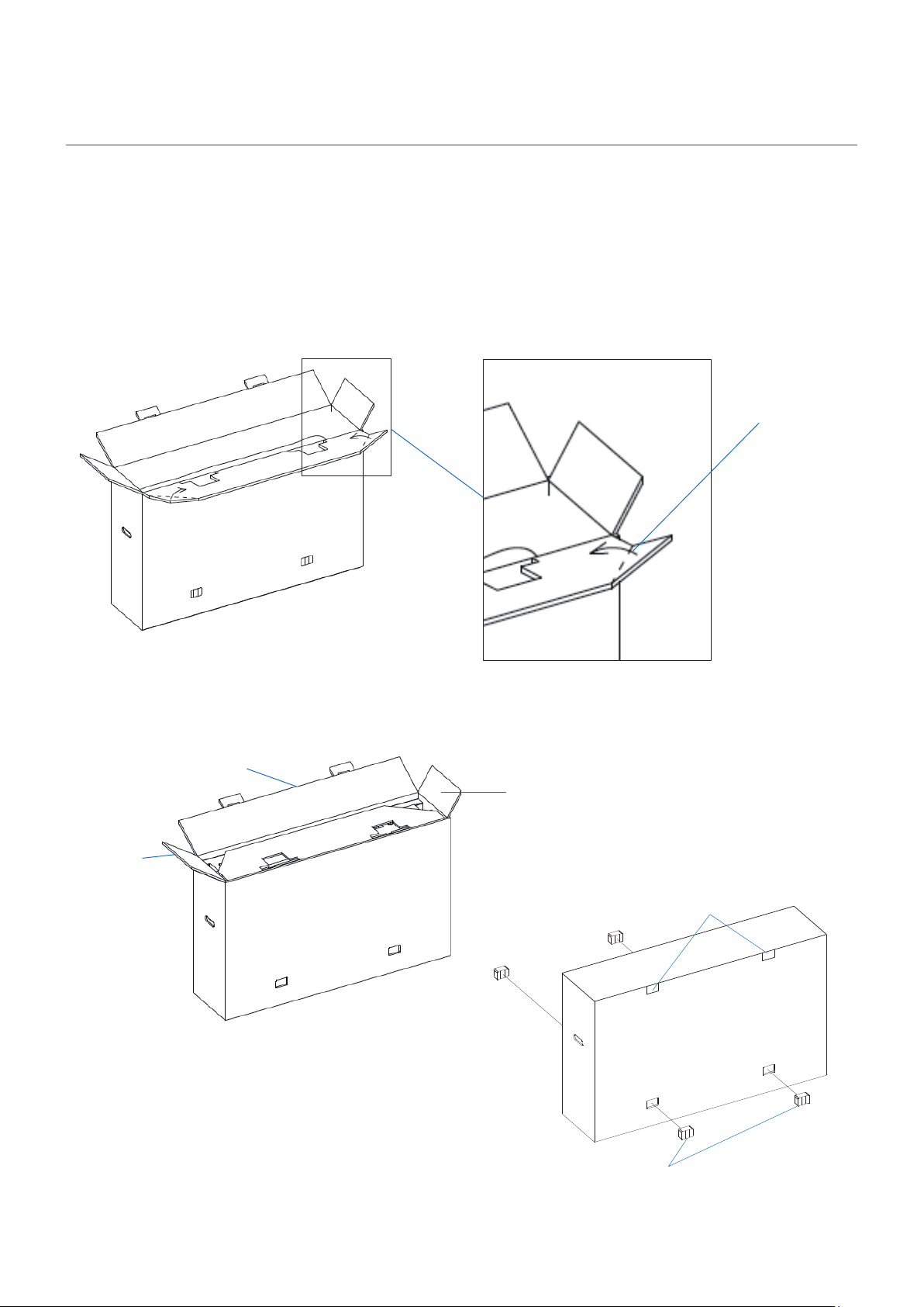
(1) Fold the corners of the front ap inward following the lines.
Folding line on the
front ap
(2) Fold the front ap, the aps on the sides, and then the rear ap in that order.
Rear ap
Flap on the side
Flap on the
side
(3) Insert the hooks and secure the fasteners.
Hooks
Fasteners
English
English - 25
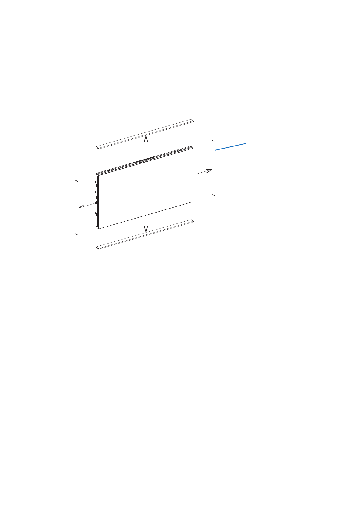
2. Models with front boards
Some models have front boards that come on the front side of the LCD.
When you want to send one of these models, always send the front boards together with the display.
The front boards are designed to protect the display from the shocks and vibrations during transportation. Sending the
display without the front boards may lead to a malfunction.
When packing the product, place the front boards rst in the lower packing materials before placing the display in the
lower packing materials.
Placing the front boards in the package after the display may lead to a malfunction.
Front board
English - 26
The repacking procedure is as follows.
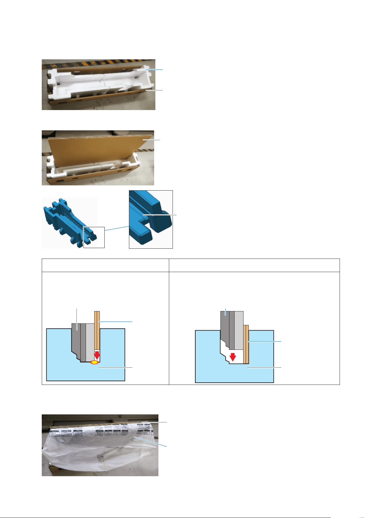
(1) Place the cushioning materials in the lower box.
Lower cushioning materials
Lower box
(2) Insert the two front boards into the grooves in the cushioning materials.
Front board
Groove
NG OK
Placing the front boards in the lower
cushioning materials after the display may lead
to a malfunction.
1) First, place the front boards in the lower cushioning materials,
2) and then place the display in the lower cushioning materials.
Front board
Display
Cushioning
materials
Front board
Display
Cushioning
materials
(3) Put the display in the protective bag and then in the lower cushioning materials.
See the gures on the aps of the box for the other packing procedures.
Display and protective bag
Front board