
Loading ...
Loading ...
Loading ...
English
10
OPERATION
WARNING: To reduce the risk of serious personal
injury, turn unit off and disconnect it from
power source before making any adjustments or
removing/installing attachments or accessories.
An accidental start-up can causeinjury.
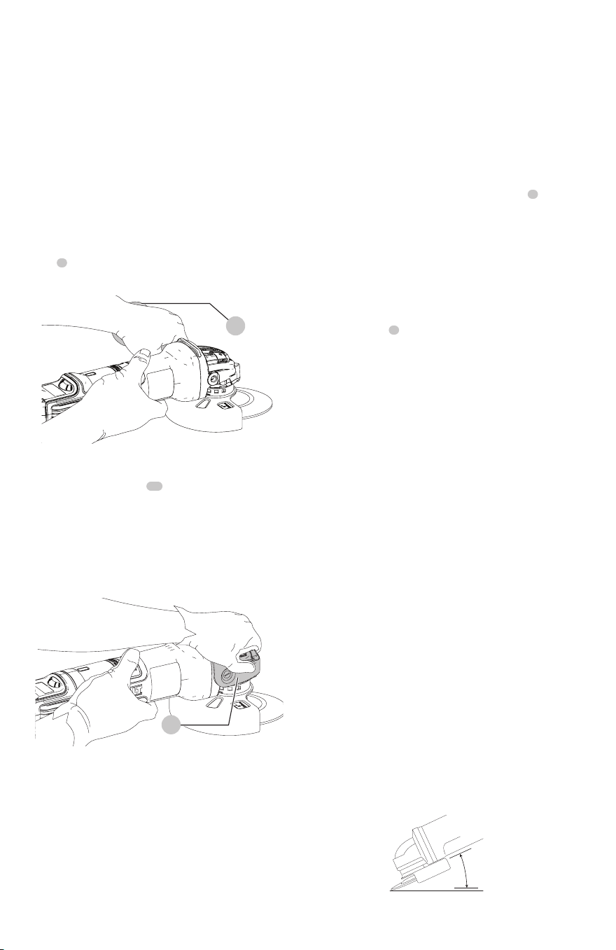
Proper Hand Position (Fig. H, I)
WARNING: To reduce the risk of serious personal injury,
ALWAYS use proper hand position asshown.
WARNING: To reduce the risk of serious personal
injury, ALWAYS hold securely in anticipation of a
suddenreaction.
Proper hand position requires one hand on the side
handle
5
, with the other hand on the body of the tool, as
shown in FigureH.
Fig. H
5
Proper hand position with the gear case grip installed
requires one hand on the body of the tool, with the other
hand on the gear case grip
11
, as shown in FigureI.
WARNING: The gear case grip is only to be used as
a gripping surface for grinding and cleaning when
precise control is needed to ensure accuracy. As with
any gripping surface, maintain firm grip during use.
The side handle should be used as the secondary grip
surface for other applications.
Fig. I
11
Slider Switch (Fig. A)
CAUTION: Hold the side handle and body of the tool
firmly to maintain control of the tool at start up and
during use and until the wheel or accessory stops
rotating. Make sure the wheel has come to a complete
stop be fore laying the tooldown.
nOTE: To reduce unexpected tool movement, do not
switch the tool on or off while under load conditions. Allow
the grinder to run up to full speed before touching the work
surface. Lift the tool from the surface before turning the tool
off. Allow the tool to stop rotating before putting itdown.
WARNING: Before connecting the tool to a power
supply, be sure the slider switch is in the off position
by pressing the rear part of the switch and releasing.
Ensure the slider switch is in the off position as
described above after any interruption in power
supply to the tool, such as the activation of a ground
fault interrupter, throwing of a circuit breaker,
accidental unplugging, or power failure. If the slider
switch is locked on when the power is connected, the
tool will startunexpectedly.
To start the tool, slide the ON/OFF slider switch
8
toward
the front of the tool. To stop the tool, release the ON/OFF
sliderswitch.
For continuous operation, slide the switch toward the front
of the tool and press the forward part of the switch inward.
To stop the tool while operating in continuous mode, press
the rear part of the slider switch andrelease.
Spindle Lock (Fig. A)
The spindle lock
2
is provided to prevent the spindle from
rotating when installing or removing wheels. Operate the
spindle lock only when the tool is turned off, unplugged
from the power supply, and has come to a completestop.
NOTICE: To reduce the risk of damage to the tool, do
not engage the spindle lock while the tool is operating.
Damage to the tool will result and attached accessory
may spin off possibly resulting ininjury.
To engage the lock, depress the spindle lock button
and rotate the spindle until you are unable to rotate the
spindlefurther.
Surface Grinding, Sanding, Wire Brushing
and Finishing (Fig. J)
CAUTION: Always use the correct guard per the
instructions in thismanual.
WARNING: Metal dust build-up. Extensive use
of flap discs in metal applications can result in the
increased potential for electric shock. To reduce
this risk, use a ground fault circuit interrupter
(GFCI) protected supply and clean the ventilation
slots daily by blowing dry compressed air into the
ventilation slots in accordance with the below
maintenanceinstructions.
To perform work on the surface of a workpiece:
1. Allow the tool to reach full speed before touching the
tool to the worksurface.
2. Apply minimum pressure to the work surface, allowing
the tool to operate at high speed. Material removal rate
is greatest when the tool operates at highspeed.
Angle
Fig. J
Loading ...
Loading ...
Loading ...