
www.manitowocfsusa.com 800-225-9916 1
Refrigeration System
Installation & Operation
Manual
Manitowoc Foodservice Walk-In Division
2915 Tennessee Avenue North
Parsons, TN 38363
Phone: 800-225-9916
www.manitowocfsusa.com
550001058-5
September 2013

www.manitowocfsusa.com 800-225-9916 2
Table of Contents
Safety Information .…………………..………………………………………. 3
Receiving Inspection ……………………………………………………. ….. 4
Locating and Mounting Condensing Units ………………………………… 4 - 5
Locating and Mounting Evaporator Coils …………………………………. 6
Wiring …………………………………………………………………………. 7
Piping …………………………………………………………………………. 7 - 10
Leak Test ……………………………………………………………………… 11
Evacuation ……………………………………………………………………. 12
Refrigerant Charging ………………………………………………………… 13
Operational Start-Up ….……………………………………………………… 13 – 15
Compressor Superheat ……………………………………………………… 16
Evaporator Superheat ………………………………………………………. 17
Electric Defrost Timer ……………………………………………………….. 18
Air Defrost Timer …………………………………………………………….. 19
Maintenance ………………………………………………………………….. 20
Troubleshooting Charts ……………………………………………………… 21 – 23
Warranty Information ………………………………………………………… 23
System Start-Up Data Sheet ………………………………………………… 24
Wiring Diagrams……………………………………………………………… 26 – 36
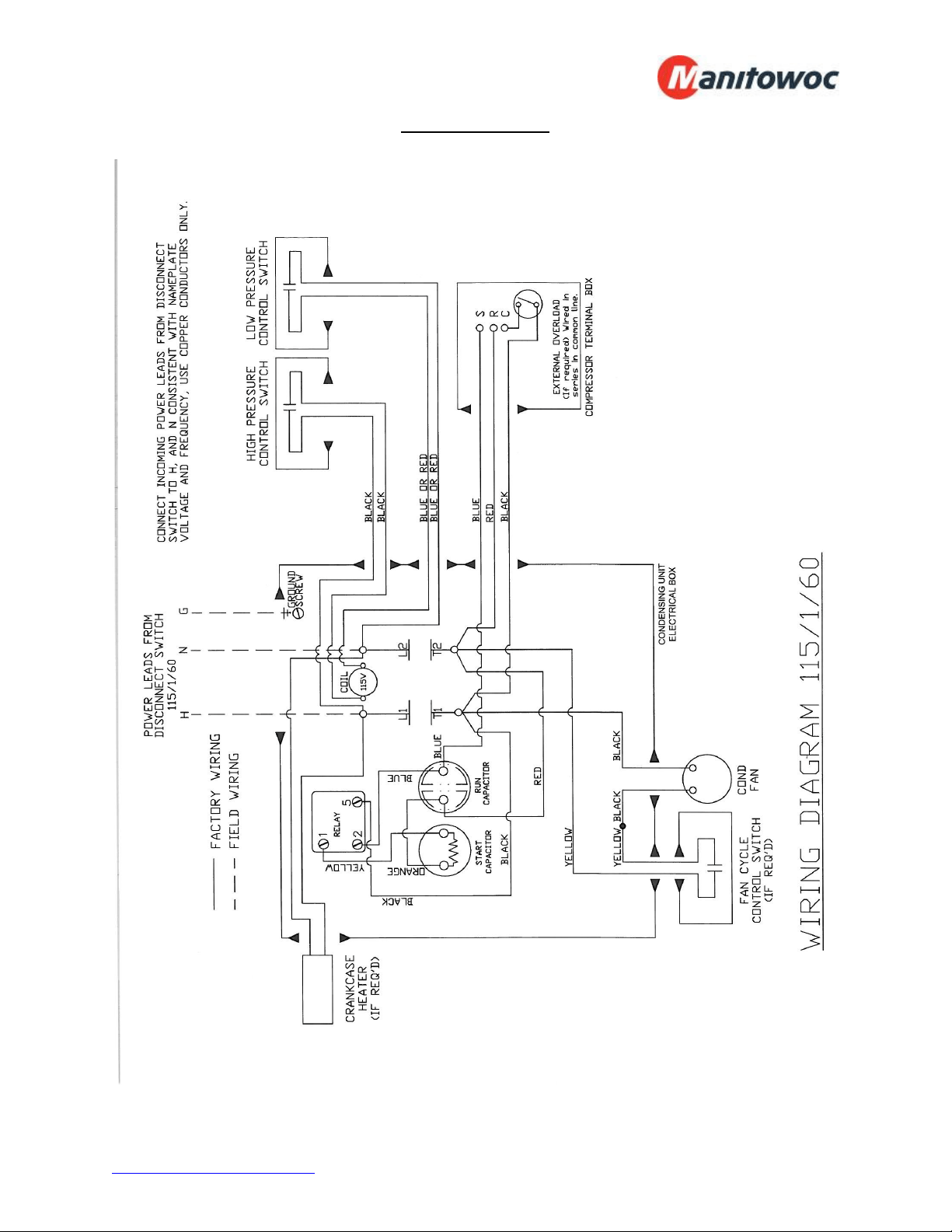
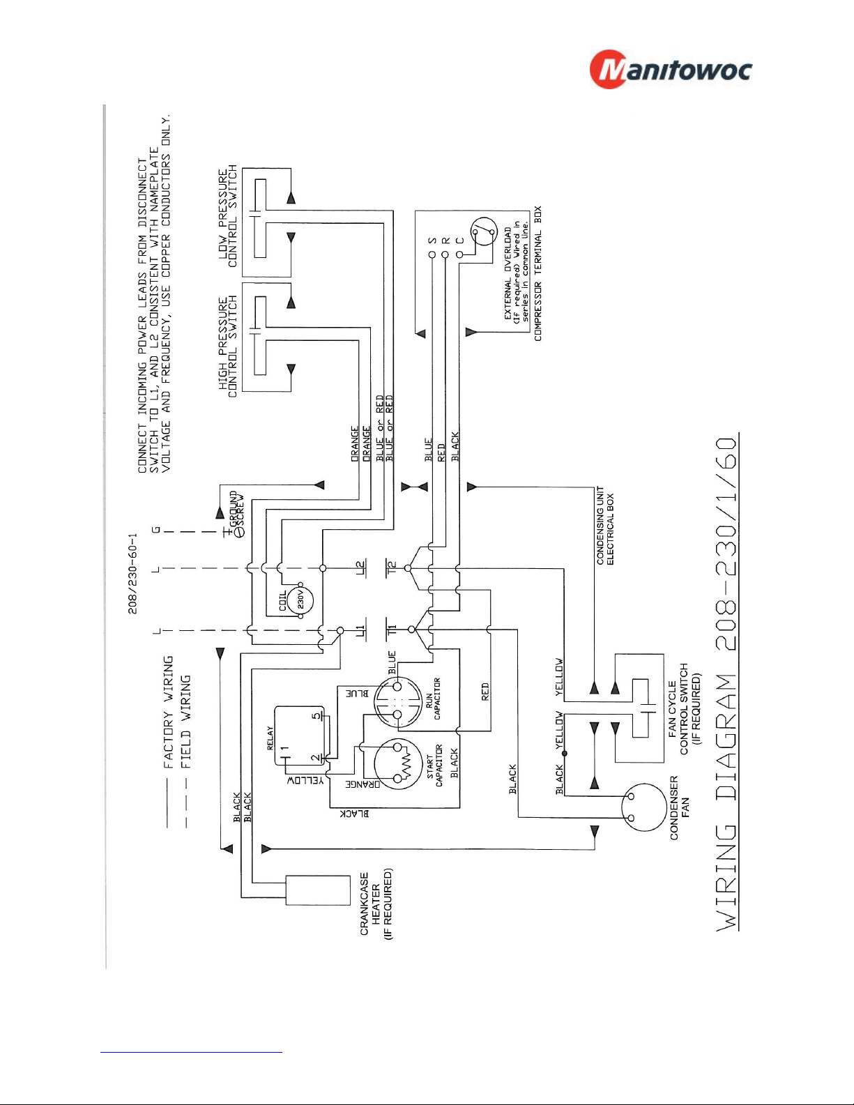
Condensing Unit 208-230/1/60…………………...………………………… 26
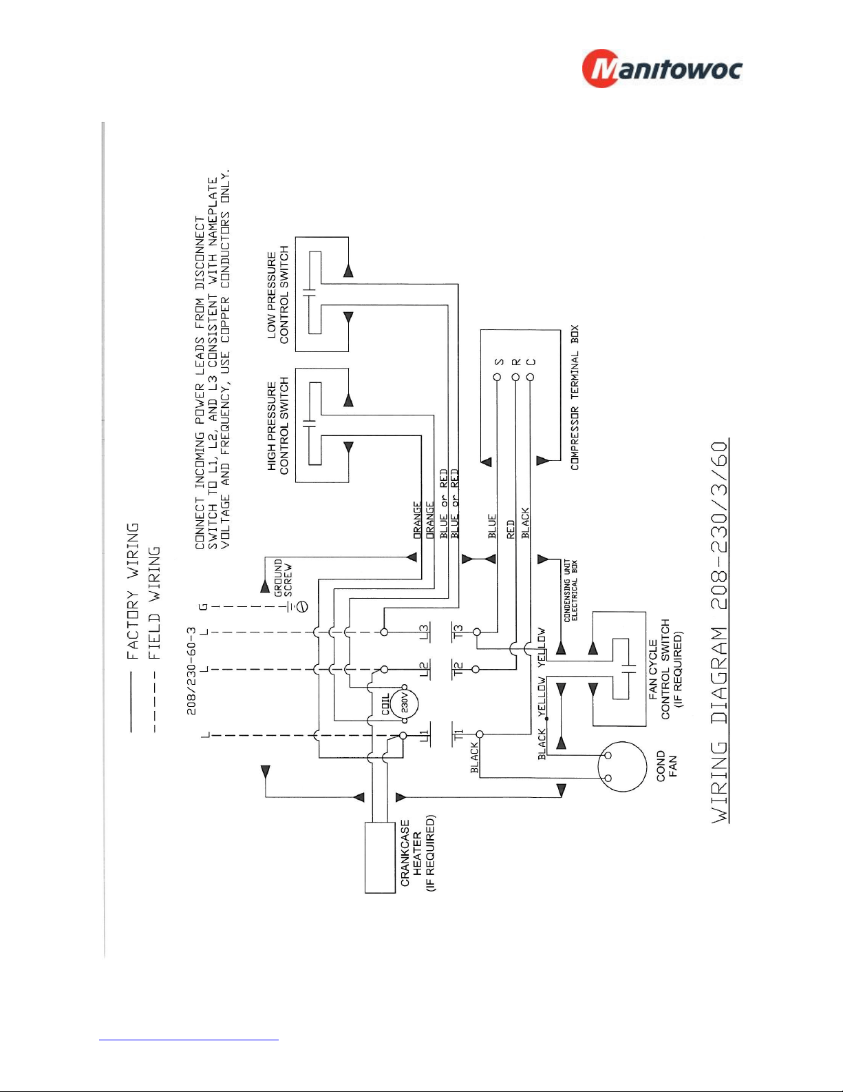
Condensing Unit 208-230/3/60……………………………………………… 27
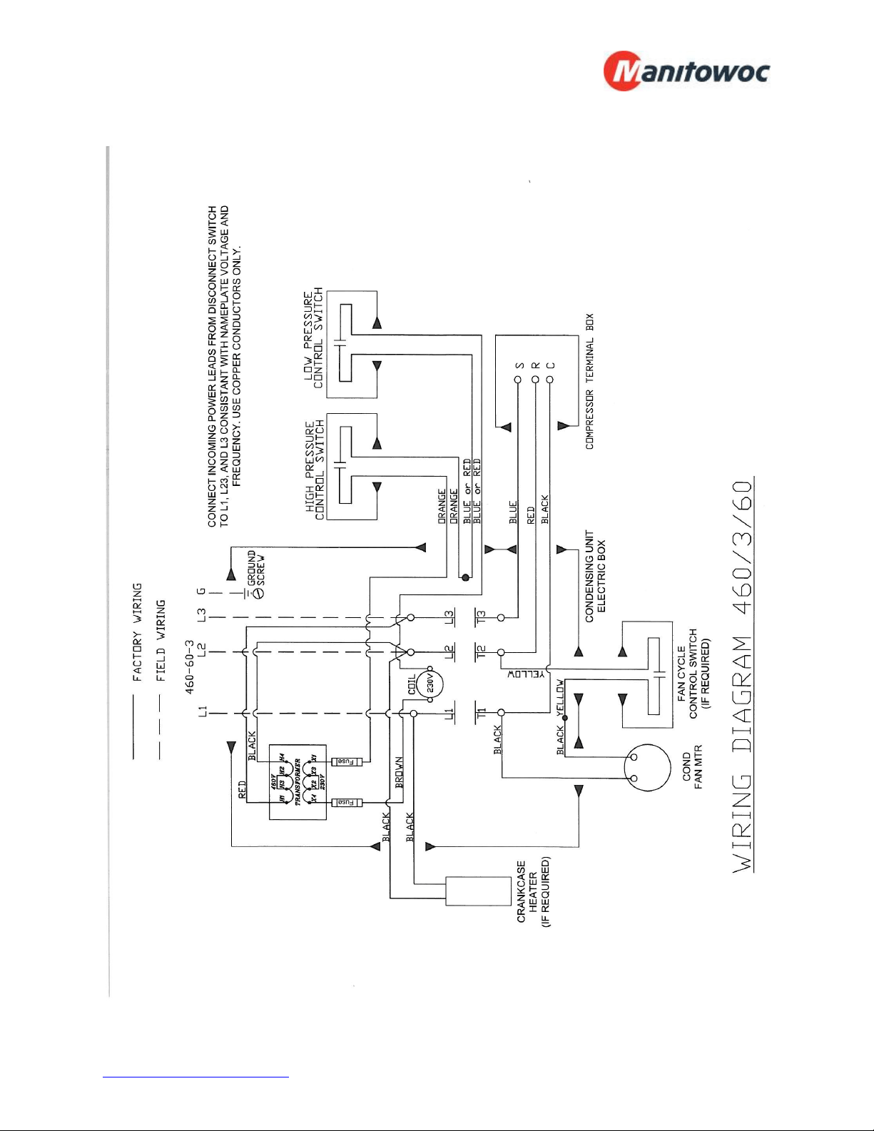
Condensing Unit 460/3/60…………………………………………………… 28
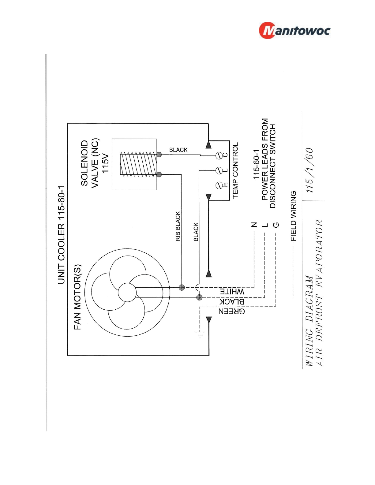
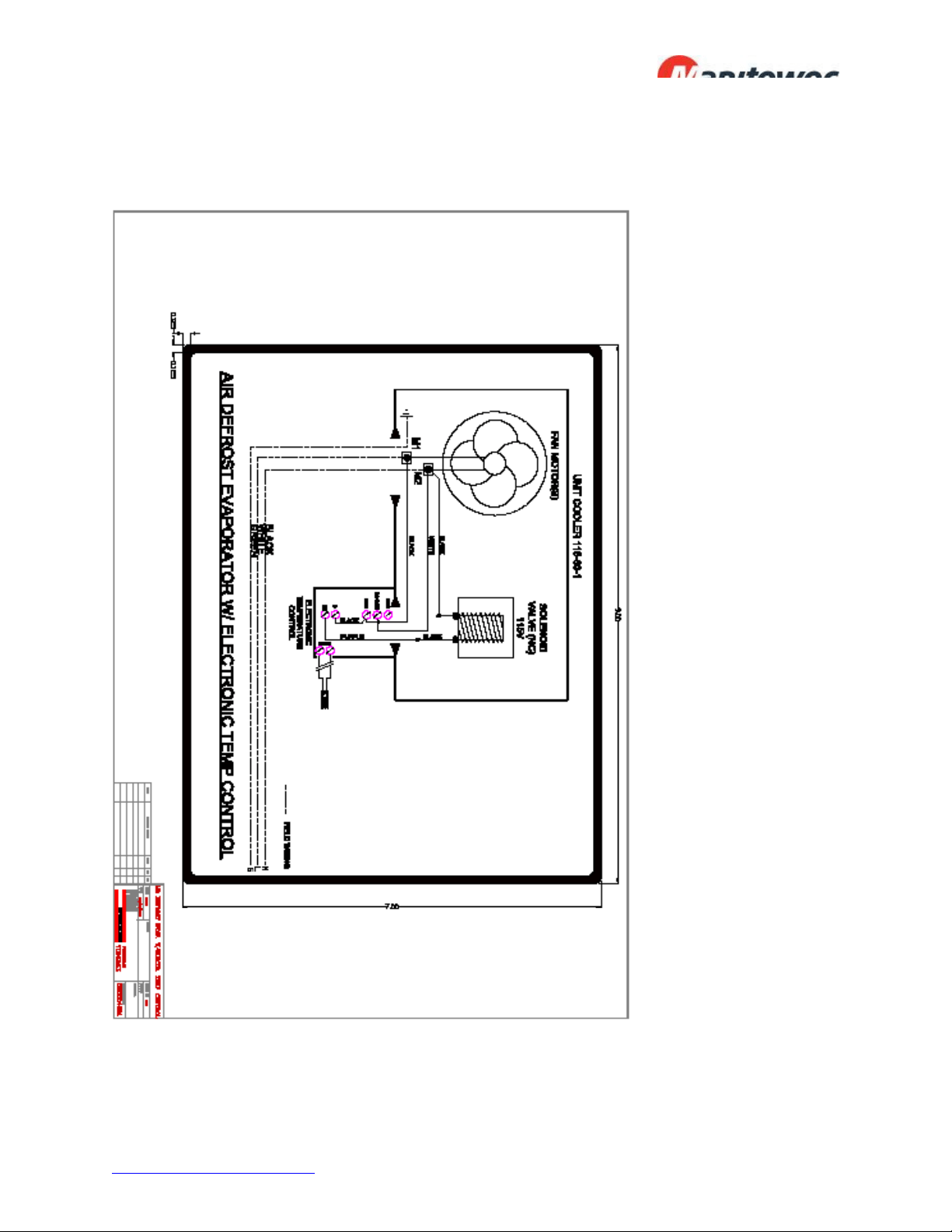
Air Defrost Evaporator 115/1/60…………..………………………………… 29
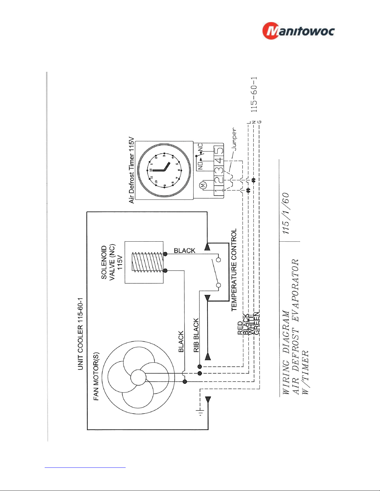
Air Defrost Evaporator with Timer 115/1/60………………………………. 30
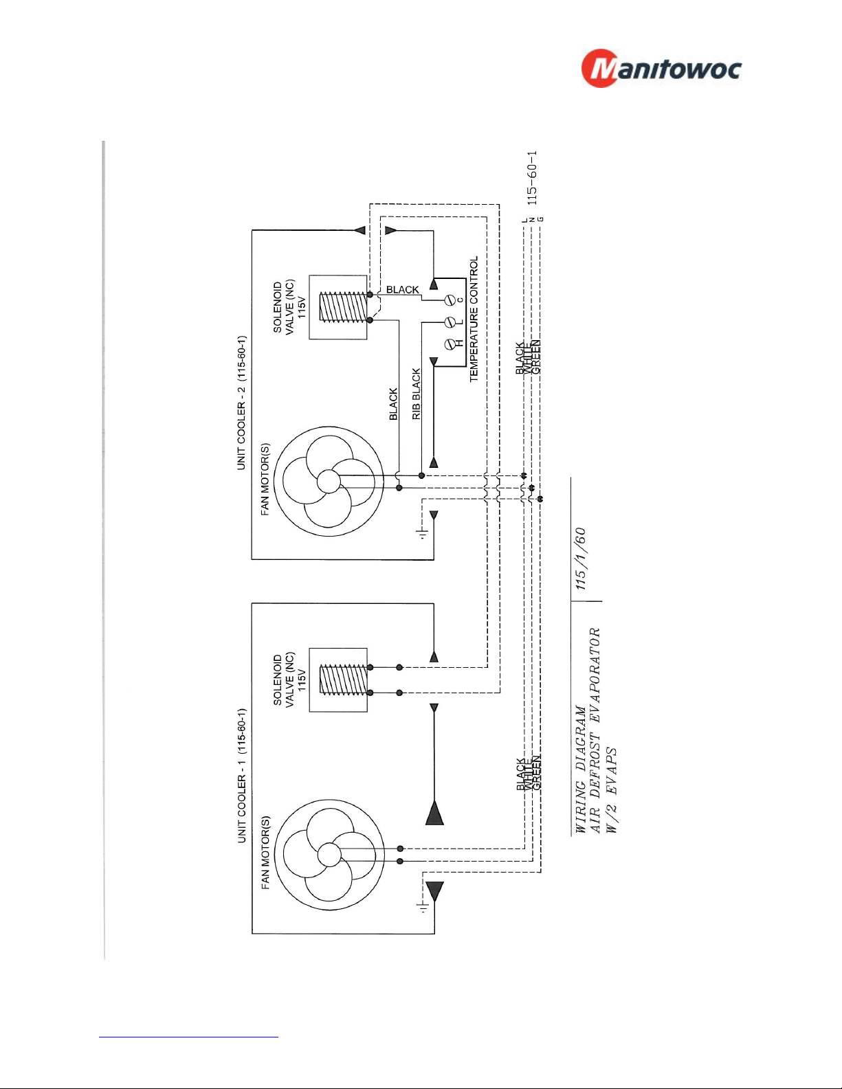
Air Defrost Evaporator with 2 Evaps 115/1/60……..……………………… 31
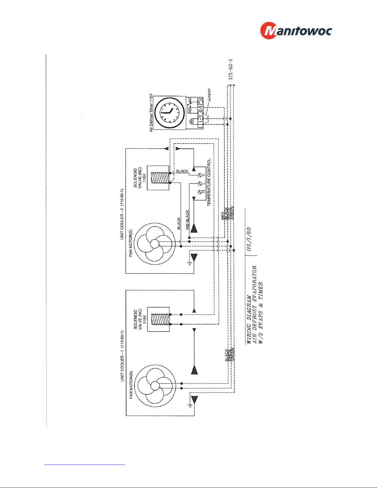
Air Defrost Evaporator with 2 Evaps & Timer 115/1/60………………….. 32
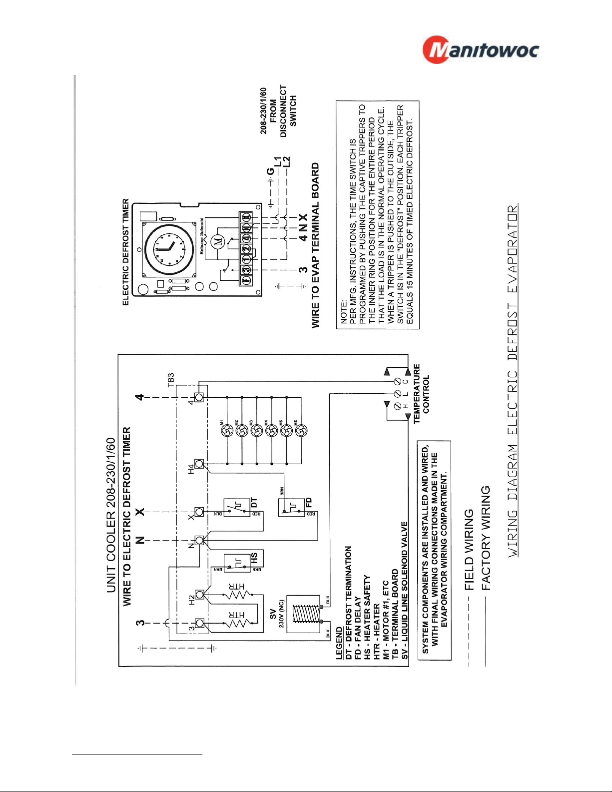
Electric Defrost Evaporator 208-230/1/60………..………………………… 33
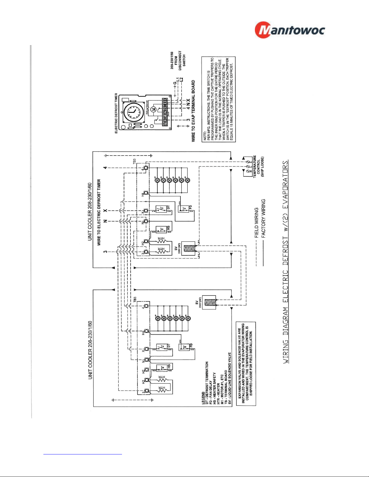
Electric Defrost with 2 Evaps 208-230/1/60………..…………………….… 34
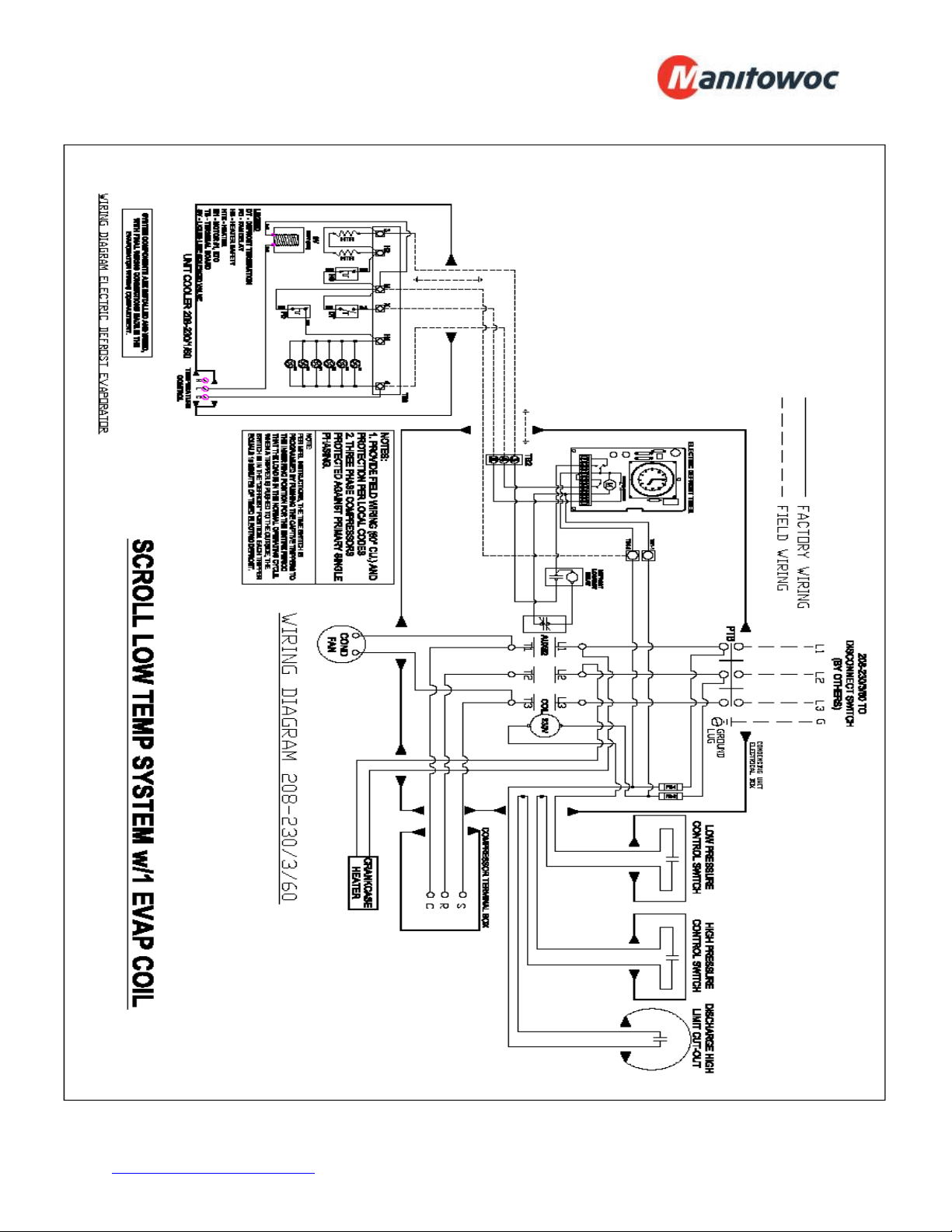
Scroll Low Temp System with 1 Evap…….………..…………………….… 35
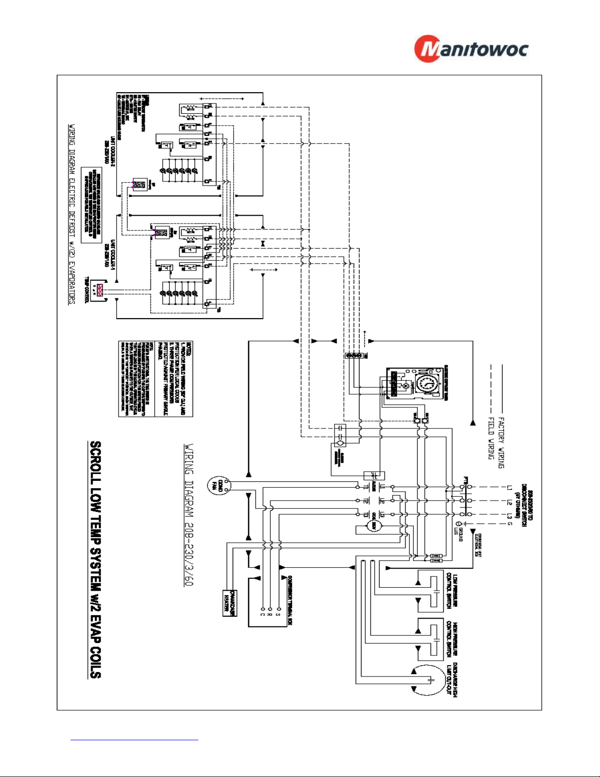
Scroll Low Temp System with 2 Evaps…….………..…………………….. 36
www.manitowocfsusa.com 800-225-9916 3
General Safety Information
Read this manual carefully before beginning the installation and operation of the
refrigeration system. Special attention is required to all sections identified with the
following warning and caution notices:
WARNING
Text in a Warning box alerts you to a potential personal injury situation. Read each
Warning statement before proceeding and work carefully.
CAUTION
Text in a Caution box alerts you to a situation in which you could damage the
refrigeration system. Read each Caution statement before proceeding and work
carefully.
Disregarding these special notices may result in personal injury and/or damage to the
refrigeration system.
Safety Notices:
Installation and maintenance/servicing are to be performed only by trained and
qualified personnel familiar with commercial refrigeration systems.
Ensure that all field wiring conforms to the equipment requirements and all
applicable local and national codes.
Disconnect all power sources before servicing the refrigeration equipment.
Sheet metal and coil surfaces have sharp edges. Use appropriate protective
gloves to prevent injury.
Use appropriate eye protection during installation and servicing.
www.manitowocfsusa.com 800-225-9916 4
Receiving Inspection
Check the shipment carefully and compare to the bill of lading. Account for all items
listed and inspect each container for damage. Carefully inspect for any concealed
damage. Report any shortages or damages to the carrier, note on the bill of lading, and
file a freight claim.
Damaged material cannot be returned to the manufacturer without prior approval. A
Return Material Authorization (RMA) must be obtained. Contact a sales representative
at 800-826-7036.
Locating and Mounting Condensing Unit
General Guidelines:
Check the selected installation location to ensure that racks, braces, flooring,
foundations, etc. are adequate to support the condensing unit weight.
The installation location is clean, dry, and level.
Locate away from corrosive and noise sensitive atmospheres.
Use the condensing unit skid and base when moving the unit. Do not remove
unit from skid until the unit is moved to the mounting location.
Mount the condensing unit base to pads or structural rails using properly sized
bolts through the unit base.
WARNING
Do not lift the condensing unit by the refrigerant tubing or components. These features
will not support the condensing unit weight. Injury and unit damage may occur!
CAUTION
Do not leave the condensing unit mounted to the wooden skid. This prevents all of the
unit supports from contacting the mounting surface. Excessive vibration and premature
equipment failure can occur.
www.manitowocfsusa.com 800-225-9916 5
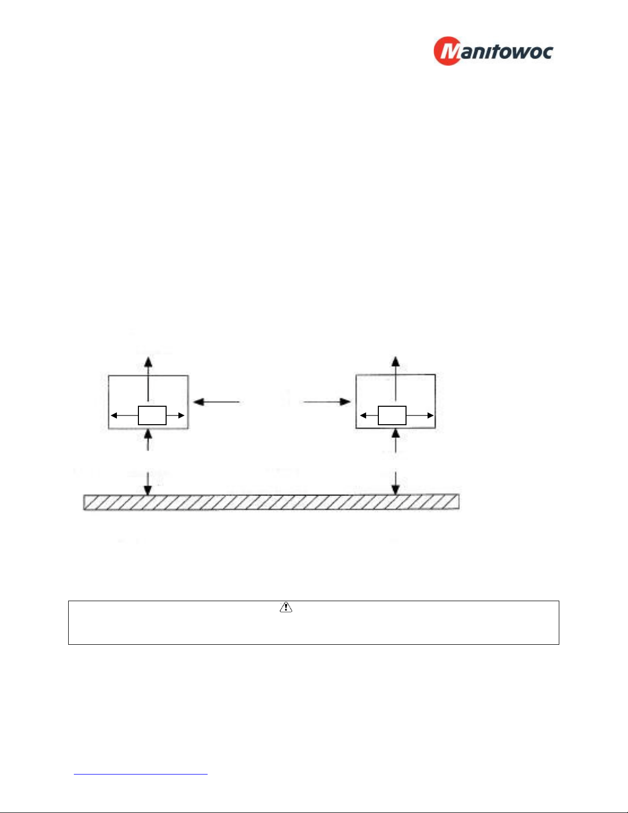
Clearance Requirements:
Locate where there is a sufficient and unrestricted supply of clean ambient air.
Locate where this is adequate space for the removal of the heated discharged air
from the condensing unit area.
Do not position multiple units so that discharge air from one unit is blowing into
the condenser inlet air of the other unit.
All sides of the unit should be positioned a minimum distance equal to the total
width of the condensing unit away from any other unit, wall, or obstruction.
Example of Multiple Units with Horizontal Airflow
CAUTION
Failure to observe clearance and air flow requirements will result in poor system
performance and premature equipment failure!
BUILDING WALL
(VIEWED FROM ABOVE)
AIR
FLOW
AIR
FLOW
MINIMUM
DISTANCE
24”
INTAKE AIR
MINIMUM DISTANCE 24”
24”
INTAKE AIR
MINIMUM DISTANCE 24”
24”
www.manitowocfsusa.com 800-225-9916 6
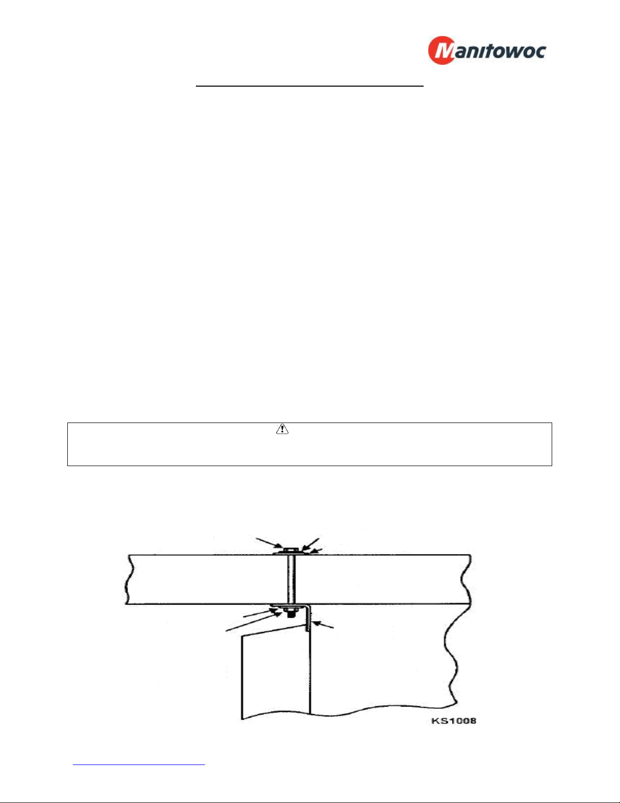
Locating and Mounting Evaporator Coil
General Guidelines:
Do not place the evaporator above or close to door openings. This will help
prevent potential icing problems.
Allow a minimum clearance equal to or greater than the coil height on all sides of
the coil for proper air flow and service access.
Use the evaporator coil for a template to locate and drill the mounting holes (1/2”
diameter).
Place a 1” and a 1-5/8” washer on each nylon bolt and insert through the drilled
mounting holes.
Lift the evaporator coil until the nylon bolts extend through the mounting
brackets.
Install washers and secure with nuts. Tighten until the coil is firm against the
ceiling. The evaporator coil must be level.
Additional information is available in the installation manual supplied with the
evaporator.
CAUTION
Failure to observe clearance and air flow requirements will result in poor system
performance and premature equipment failure!
Evaporator Coil Mounting Diagram
Evaporator
Mounting
Bracket
Nylon Bolt 1” O.D. washer
1-5/8” O.D. washer
Nut
1” O.D. washer
Note
:
Fasteners are
supplied in the
mounting kit.
www.manitowocfsusa.com 800-225-9916 7
Wiring
All electrical connections and routing must comply with local and national codes. Do not
modify the factory installed wiring without written factory approval. The field wiring must
enter through the knockouts provided. Refer to the nameplate on the condensing or
evaporator coil to determine the proper electrical power supply. Wire type should be of
copper conductor only and properly sized to handle the electrical load. The unit and coil
must be properly grounded. Condensing unit wiring diagrams are attached inside the
electrical box cover. Evaporator coil wiring diagrams are located inside the installation
folder. Copies of the wiring diagrams are also available in the back of this manual.
WARNING
All wiring must comply with local and national codes. Wiring must be performed only by
a refrigeration technician or certified electrician. Failure to follow these guidelines may
result in injury!
CAUTION
Check all wiring connections, including factory terminals, before operation. Connections
can become loose during shipment and installation.
Piping
General Requirements:
All refrigeration piping and components are to be installed in accordance with applicable
local and national codes and in conformance with industry refrigeration guidelines to
ensure proper operation of the refrigeration system. Only refrigeration grade copper
tubing should be used. Long radius elbows should be used. Short radius elbows have
points of excessive stress concentration and are subject to breaking at these points, do
not use short radius elbows. Suction lines must be insulated with a minimum ¾” thick
armaflex to reduce heat pick-up.
www.manitowocfsusa.com 800-225-9916 8
Cleanliness:
Condensing units and evaporator coils are cleaned and dehydrated at the factory. The
condensing unit must remain closed and pressurized until the piping is complete and
final connections are ready to be made.
CAUTION
The maximum air exposure for dehydrated condensing units is 15 minutes. Systems
exposed longer than 15 minutes must have the compressor oil and drier filter replaced.
Leaving a system exposed to the atmosphere for more than 15 minutes can result in
premature system failure.
Do not remove system tubing covers until work is ready to be performed. Ensure that
all refrigeration tubing is clean and dry prior to installation. Use only tubing cutters when
trimming tubing to the proper length. Do not use saws to cut tubing.
CAUTION
The use of saws to cut tubing can contaminate the system with copper chips causing
premature system failure.
Brazing joints require a dry inert gas, typically nitrogen, be passed through the lines at a
low pressure to prevent scaling and oxidation. Use only silver solder brazing alloys.
Minimize the amount of flux to prevent internal contamination. Flux only the male
portion of the joint. Thoroughly clean fluxed joints after brazing.
CAUTION
Dry inert gas must be passed through the system while brazing to prevent scaling and
oxidation. Scaling and oxides can clog refrigeration components resulting in system
failure.
Pipe Supports:
All tubing should be supported in a least two locations (near the end of each tubing run).
Long runs will require additional support. As a guide, support 3/8” to 7/8” pipe every five
feet, 1-1/8” to 1-3/8” every seven feet, and 1-5/8” to 2-1/8” every ten feet. Do not leave
a corner unsupported when changing directions. Place supports within 2 feet of each
direction change. Piping that is attached to a vibrating object (such as a compressor or
compressor base) must be supported in a manner that will not restrict the movement of
the vibrating object. Rigid mounting will fatigue the tubing causing refrigerant leaks.
www.manitowocfsusa.com 800-225-9916 9
Oil Traps:
To ensure proper oil return to the compressor, a P-type oil trap should be installed at
the base of each suction riser of four feet or more. The suction trap must be the same
size as the suction line. Additional traps are necessary for long vertical risers. Add a
trap for each length of pipe (approximately 20 feet) to insure proper oil return. Suction
lines must slope ¼” per 10 feet toward the compressor. Install a suction line trap at the
evaporator outlet if the suction line rises to a point higher than the connection on the
evaporator.
CAUTION
Failure to properly install oil traps can prevent sufficient oil return to the compressor
resulting in premature compressor failure.
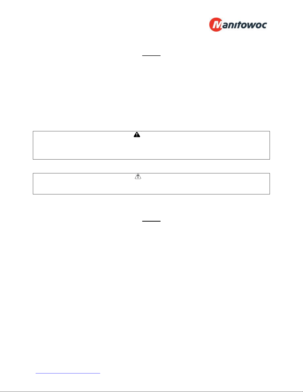
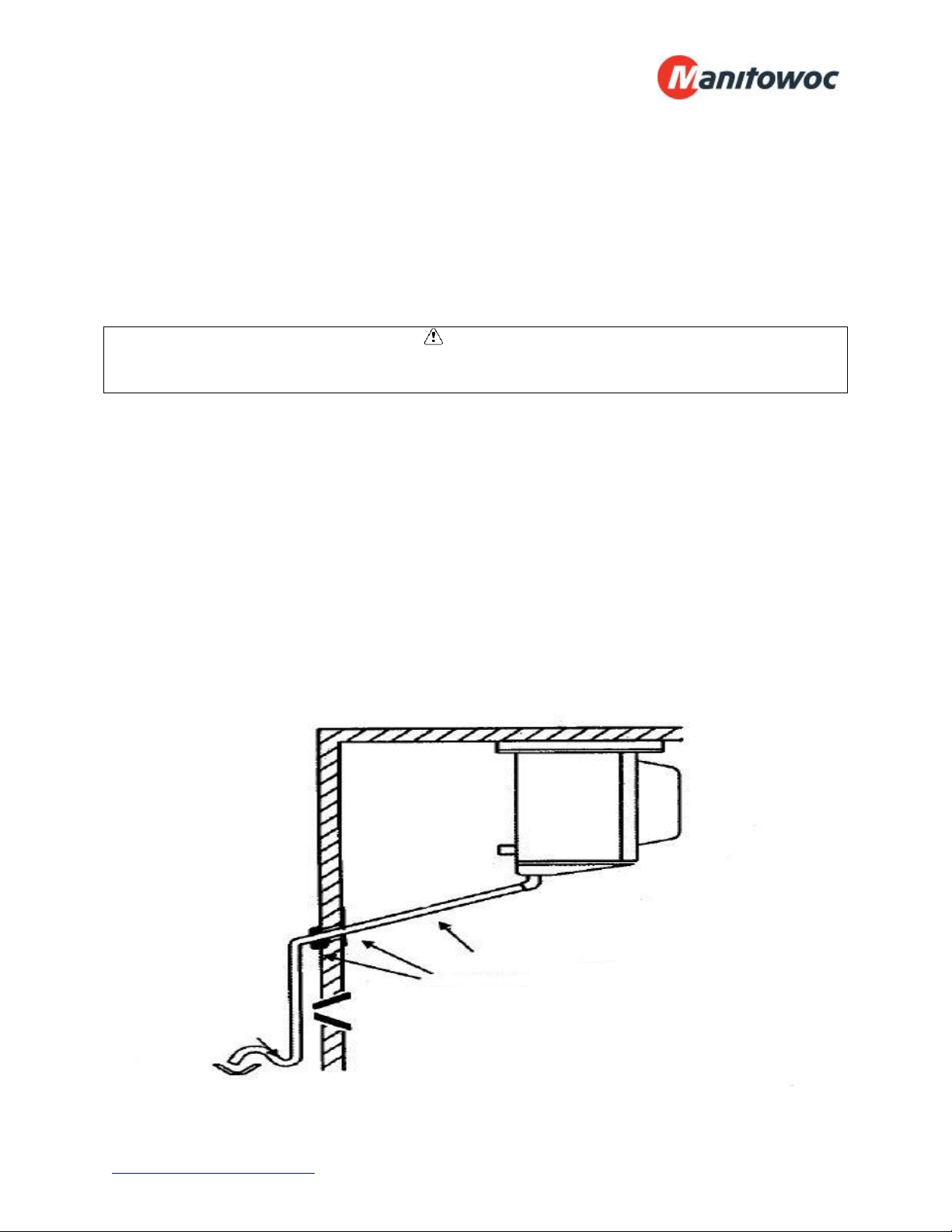
Drain Lines:
Evaporator coil drain lines should be pitched a minimum of ½” per foot to allow proper
drainage and exit the walk-in as quickly as possible. Insulate and seal the drain line
where it passes through the wall. Copper drain line is required. If the refrigerated
space is 33°F or lower, drain line insulation and heat tape are required. Drain lines
must be insulated with minimum ½” thick armaflex. The drain line heat tape must be
wrapped around the copper drain line. Do not locate bends, elbows, or drain traps
within the refrigerated space. Do not reduce the drain line size. Locate a drain line P-
trap outside of the refrigerated space. Any traps exposed to low ambient temperatures
should be wrapped with a drain line heater (provide 20 watts of heat per foot of drain
line at 0°F, 30 watts per foot at -20°F.
P-Trap
Pitch drain line
½” per foot
Seal and
Insulate
Typical Drain Installation
www.manitowocfsusa.com 800-225-9916 10
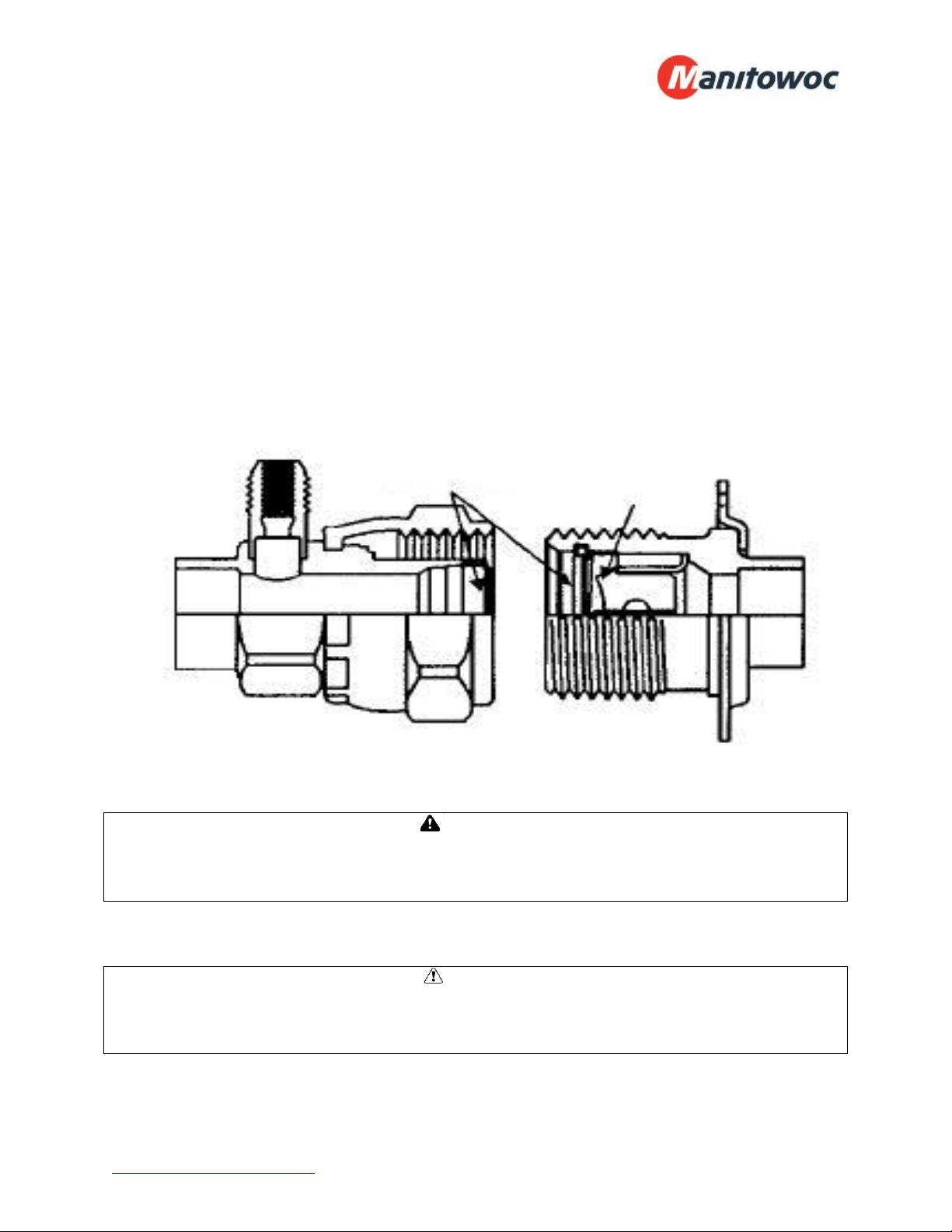
Pre-Charged lines and Quick Connects:
Route the suction and liquid line sets between the condensing unit and evaporator coil
following the piping guidelines identified in this manual. Remove the dust caps from the
quick connect fittings and verify that the o-rings are intact. Wipe the coupling seals and
threaded surfaces with a clean cloth to prevent contamination. Lubricate the threads
and o-rings with Polyol Ester oil. Thread the coupling halves together by hand to
ensure proper thread mating. Tighten with a wrench until the coupling bodies “bottom”
or until there is definite resistance. Tighten an additional ¼ turn to ensure proper brass-
to-brass seating. Once the system is opened and pressurized, check each fitting for
refrigerant leaks. If a leak is detected, tighten until the leak stops.
WARNING
Do not loosen and disconnect the quick connect fittings before reclaiming the refrigerant
and depressurizing the system. Disconnecting a pressurized system can result in
injury!
CAUTION
Quick connects are for one time use only. Once disconnected, the coupling cannot be
re-used. Refrigerant leaks will occur if the couplings are re-used resulting in poor
system performance.
Diaphragms
Cutter
www.manitowocfsusa.com 800-225-9916 11
Leak Testing
After all connections are complete the refrigeration system must be tested for leaks.
Failure to perform a leak test can result in unsatisfactory system performance,
additional servicing and service costs, and possible system failure. Leak test should be
performed using an electronic leak detector. All joints and components, both factory
and field installed, should be thoroughly inspected for leaks. The system installation
must be leak free!
Leak Testing “PR” model systems:
Open both the liquid and suction service valves.
Ensure the solenoid valve is energized and open.
Add 50 psi refrigerant, then pressurize with dry nitrogen to the low side test
pressure identified on the unit rating label.
Allow thirty minutes for refrigerant to reach all parts of the system.
Check all joints and components with an electronic leak detector.
Leak Testing “PC” model systems:
Leave the service valves closed, the condensing unit is charged with refrigerant.
Ensure the solenoid valve is energized and open.
Add 50 psi refrigerant, then pressurize with dry nitrogen to the low side test
pressure identified on the unit rating label.
Allow thirty minutes for refrigerant to reach all parts of the system.
Check all joints and components with an electronic leak detector.
Leak Testing “PCL” model systems:
Open both the liquid and suction service valves.
Ensure the solenoid valve is energized and open.
Allow thirty minutes for refrigerant to reach all parts of the system.
Check all joints and components with an electronic leak detector.
If a leak is detected, relieve the pressure and/or reclaim the refrigerant and repair the
leak. If additional brazing is required, pass a dry inert gas (nitrogen) through the system
to prevent contamination. Reference page 10 of this manual for leaks located at quick
connects couplings. Retest the system as outlined above until no leaks are detected.
CAUTION
If a braze joint is detected leaking, dry inert gas must be passed through the system
while repairing the joint to prevent scaling and oxidation. Scaling and oxides can clog
refrigeration components resulting in system failure.
CAUTION
Always use the system specified refrigerant when pressuring to perform a leak test.
www.manitowocfsusa.com 800-225-9916 12
System Evacuation
Evacuation of the refrigeration system is necessary to remove all air and moisture from
the system. A reliable rotary vacuum pump with an accurate deep vacuum gauge is
recommended. Do not use the system compressor as a vacuum pump and do not
operate the compressor while the system is under vacuum.
Evacuation of “PR” model systems:
Open both the liquid and suction service valves.
Ensure the solenoid valve is energized and open.
Connect vacuum pump to the liquid and suction service valves.
Evacuate the system to 250 microns and maintain for a minimum of 4 hours.
Perform a vacuum decay test for a minimum of ten minutes to ensure the system
is leak free and dry.
Evacuation of “PC” model systems:
Leave the service valves closed, the condensing unit has been evacuated and is
charged with refrigerant.
Ensure the solenoid valve is energized and open.
Connect vacuum pump to the liquid and suction service valves.
Evacuate the system to 250 microns and maintain for a minimum of 4 hours.
Perform a vacuum decay test for a minimum of ten minutes to ensure the system
is leak free and dry.
Evacuation of “PCL” model systems:
“PCL” systems do not require evacuation; this process has been performed at
the factory.
CAUTION
Do not use the system compressor to evacuate the system. Do not start the
compressor while the system is under vacuum. This may damage to the compressor
and cause premature system failure.
www.manitowocfsusa.com 800-225-9916 13
Refrigerant Charging
The refrigerant charge should be added to the system through the liquid line service
valve. Do not charge liquid refrigerant into the suction service valve! The initial charge
should be determined by weight and sight glass indication. Start the system. If the
condensing temperature is 105° F or greater, charge the system until the sight glass
clears. If the condensing unit temperature is below 105° F, reduce the condenser face
surface area to raise the discharge pressures above 105° F and proceed to charge to a
clear sight glass. Return to a full condenser face area when charging is complete.
CAUTION
Do not charge liquid refrigerant into the suction service valve. Do not overcharge the
system. These conditions can permit liquid refrigerant to enter the compressor and
cause damage to internal components resulting in premature system failure.
Operational Start-Up
The first 2 – 4 hours of operation after initial start-up is a critical time. Do not just start
the system and leave. Pressure values, compressor and evaporator superheat, and
inspecting for excessive vibrations and loose connections are some of checks that must
be performed prior to leaving the system.
Pre-Start Checks:
Verify that all service valves are fully open.
Ensure that all refrigerant and electrical connections are tight.
Verify that the wiring and piping is properly routed and secured.
The compressor mounting bolts are properly adjusted (see compressor mounts
on page 14).
All fan motors and mounting brackets are tight.
The condensing unit base and evaporator coil are properly secured.
www.manitowocfsusa.com 800-225-9916 14
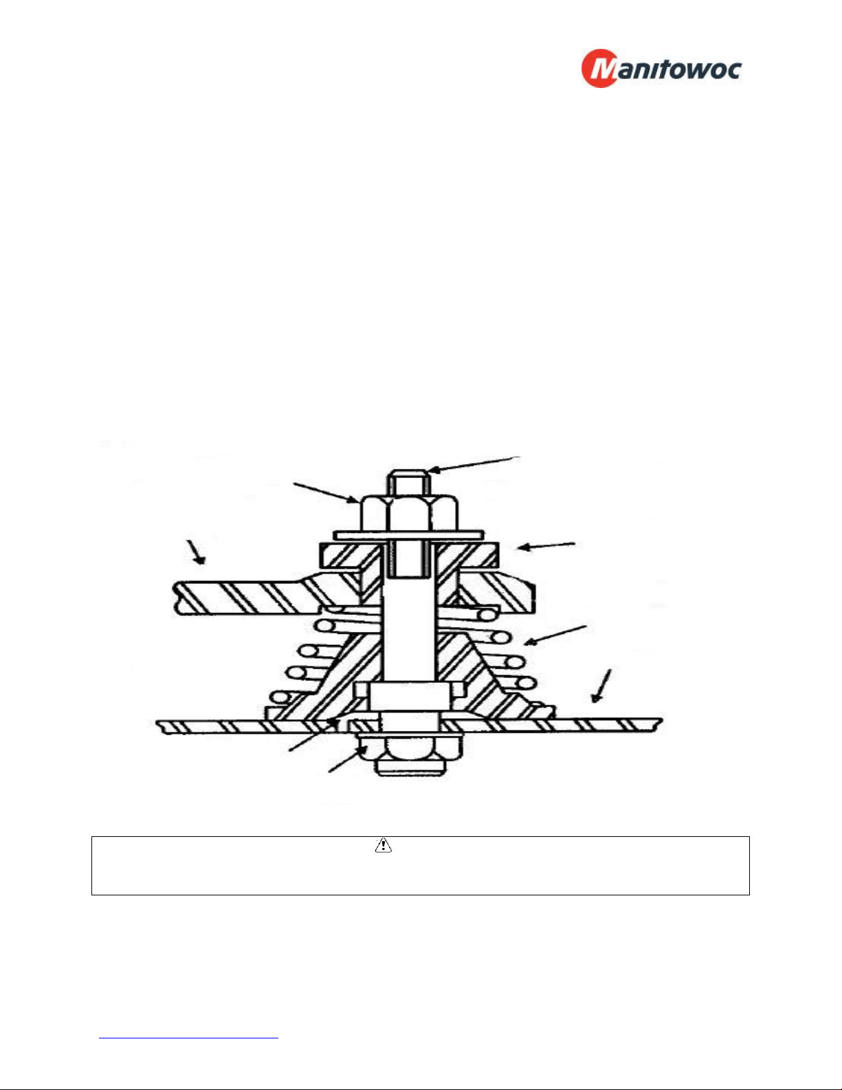
Compressor Mounts:
Hermetic Compressors – hermetic compressor springs are mounted internally; check
the compressor mounting bolts to ensure the nuts have not become loose during
shipment.
Semi-Hermetic Compressors – most semi-hermetic compressors have external spring
mounts and are factory assembled. The following actions are required once the
condensing unit is installed and before system start-up:
Loosen the upper mounting nuts.
Remove the spring steel clips from the mounting springs.
Retighten the upper mounting nuts until the compressor can float on the springs
approximately 1/16” between the mounting nut and rubber grommet.
CAUTION
Failure to ensure the compressor mounts are properly tightened can result in fatigue to
the system piping causing leaks and poor system performance.
Compressor
Mounting Foot
Mounting Nut
(Upper)
Mounting
Stud
Rubber
Spacer
Mounting
Spring
Mounting
Base
Locking
Device
Mounting Nut
(Lower)
Properly Adjusted Compressor Mount

www.manitowocfsusa.com 800-225-9916 15
Start-Up Procedure:
CAUTION
Do not start the system while in a vacuum. Do not leave the system unattended until
normal operating conditions are achieved.
Operate the system for a minimum of two hours and perform checks of the following:
Check the compressor discharge and suction pressures to ensure they are in the
normal operating range.
Check the liquid line sight glass for proper refrigerant charge.
Monitor the compressor oil level (semi-hermetic compressors), add oil as
necessary to keep the level at ¾ sight glass when idle and ½ sight glass when
running.
Check the voltage and amperage at the compressor terminals. Voltage must be
within +10% or -5% of the rating indicted on the condensing unit name plate. On
three phase compressors, verify there is a balanced load.
Check all fans on the evaporator coil and condensing unit to be sure they are
operational and turning in the correct direction.
Check the piping and electrical connections for vibration. Add supports and
strapping if needed.
Check the crankcase heater operation (if equipped).
Set the defrost control time and verify the defrost initiation settings. See pages
18 - 19 for additional details.
Set temperature control to desired temperature range.
Check the compressor and evaporator superheat (reference pages 16 - 17).
After all system checks have been checked, properly adjusted, and verified, replace all
Schrader caps, service valve caps, electrical box covers, housings, etc. File a copy of
this manual for future reference.

www.manitowocfsusa.com 800-225-9916 16
Compressor Superheat:
CAUTION
Failure to check and properly adjust compressor superheat can result in premature
system failure.
Compressor superheat is a critical value that must be checked. Check the compressor
superheat as follows:
1. Determine the suction pressure at the suction service valve of the compressor.
2. Determine the saturation temperature at the observed suction pressure using
refrigeration pressure temperature tables.
3. Measure the suction line temperature 6 -10 inches away from the compressor.
4. Subtract the saturation temperature (step 2) from the measured temperature
(step 3). The difference is the superheat of suction gas.
A low suction superheat can cause liquid to return to the compressor. This will cause
dilution of the oil and eventual failure of the bearings, rings and valves. A high suction
superheat will cause excessive discharge temperatures, which cause a breakdown of
the oil. This causes piston ring wear, and piston and cylinder wall damage. System
capacity decreases as the suction superheat increases. For maximum system capacity,
keep the suction superheat as low as practical. Copeland requires a minimum
compressor superheat of 20°F; however, to improve compressor life, 25°F to 40°F is
preferred. Adjust the expansion valve at the evaporator when adjustments to the
suction superheat are necessary. Refer to “Evaporator Superheat” on the next page for
more information.
www.manitowocfsusa.com 800-225-9916 17
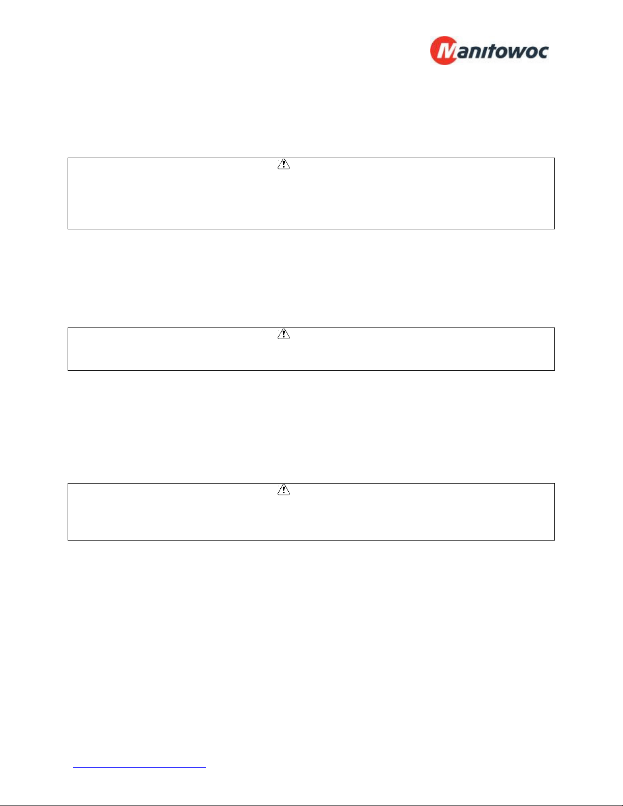
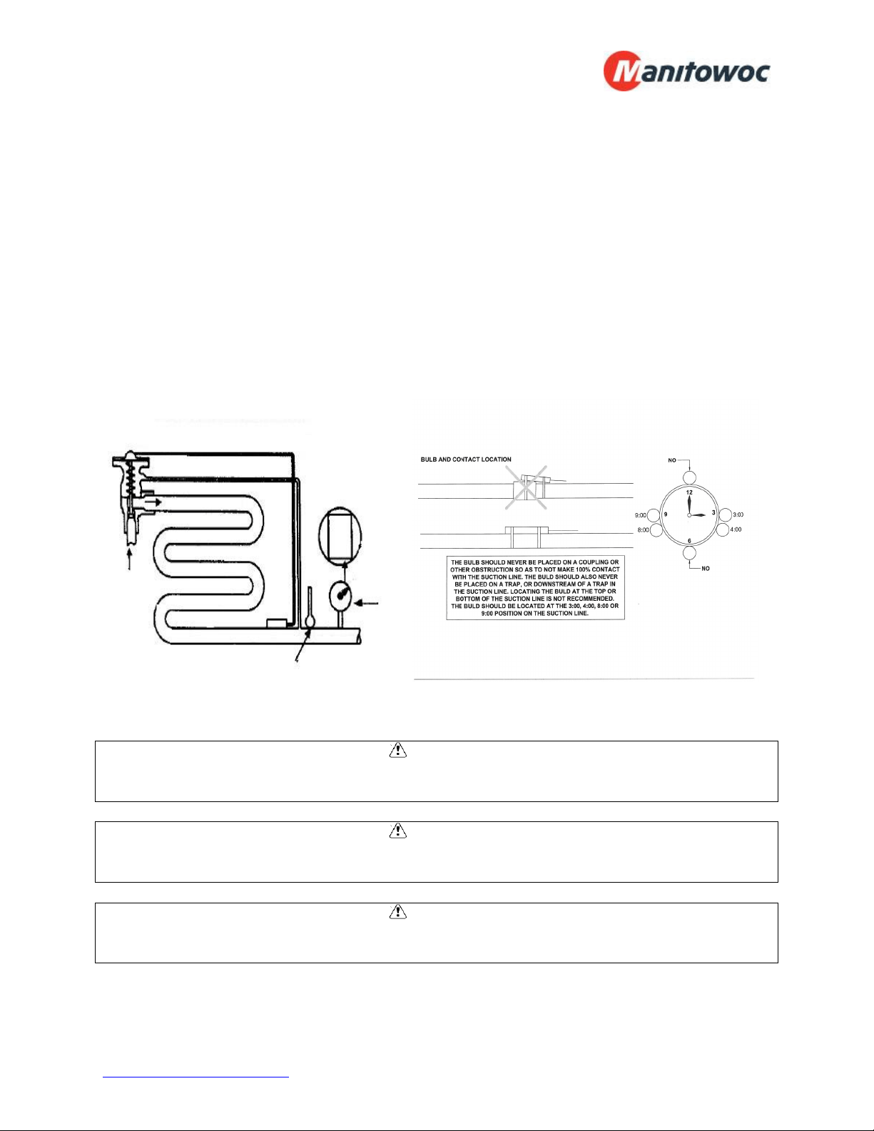
Evaporator Superheat:
Check the evaporator superheat once the walk-in has reached the desired temperature.
Generally, systems with a design temperature drop of 10°F should have an evaporator
superheat value of 6° - 10°F on freezers and 8° - 12°F on coolers for maximum
efficiency.
To determine the evaporator superheat:
1. Measure the suction pressure at the evaporator outlet.
2. Convert the pressure to saturation temperature referencing a temperature-pressure
chart.
3. Measure the temperature of the suction line at the expansion valve bulb. Ensure
the bulb is mounted at the correct location on the suction tube.
4. Subtract the saturation temperature reading (step 2) from the measured temperature
(step 3). The difference is the evaporator superheat.
CAUTION
Minimum compressor superheat of 20°F may override these recommendations on
systems with short line runs.
CAUTION
The condensing unit must have the discharge pressure above the equivalent 105°F
condensing pressure (reference refrigerant charging on page 13).
CAUTION
Correct location and full contact of the expansion valve bulb is extremely important for
proper system performance.
Temperature minus
pressure converted
to temperature
equals superheat
Temperature
Pressure
Determining Evaporator Superheat
www.manitowocfsusa.com 800-225-9916 18
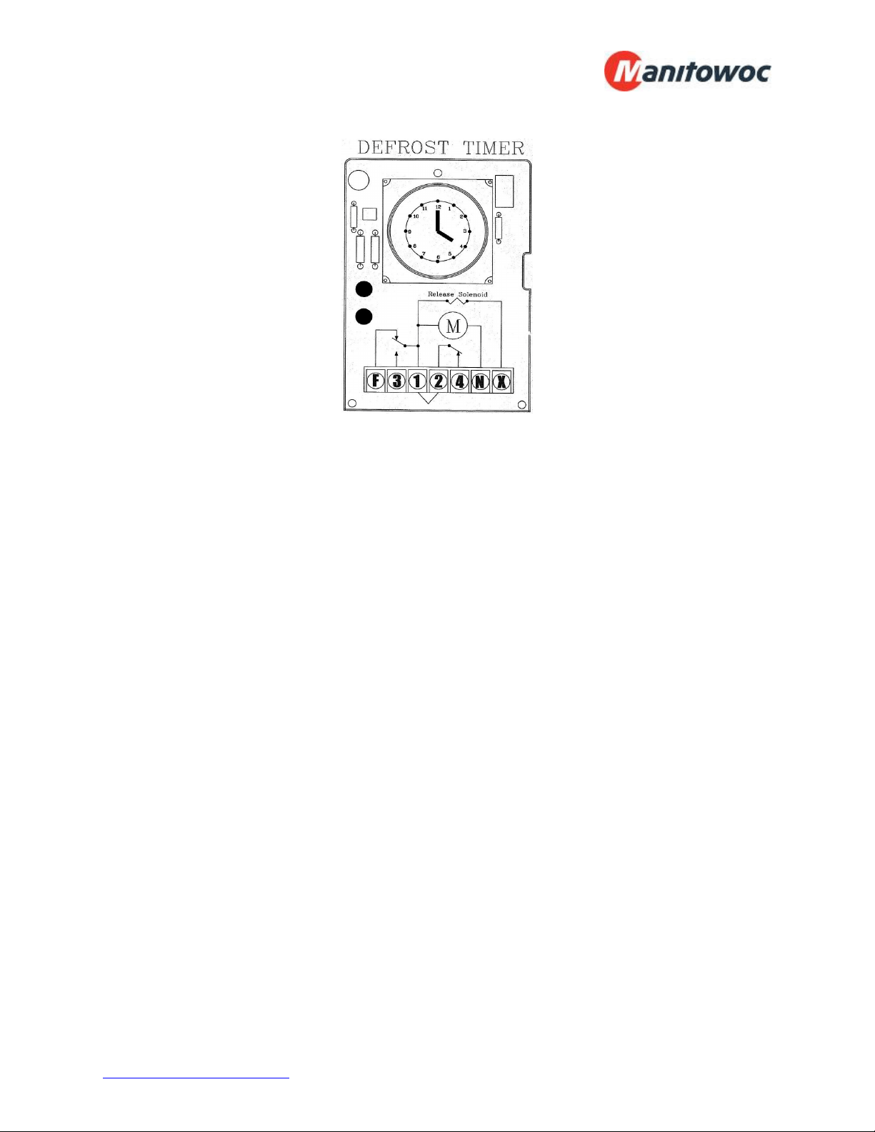
Electric Defrost Timer:
Defrost Time Clock
Instructions for setting the timer is located on the inside cover of the time clock. The defrost
timer clock must be set to the correct time at initial start-up and after any power interruptions.
Set the clock by rotating the clock face until the correct time is at the arrow on the face of the
timer.
The switch is programmed by pushing the captive trippers to the inner ring for the entire
period the load is to be turned “ON”. When a tripper is pushed to the outside, the switch is in the
“DEFROST” position. Each defrost tripper represents 15 minutes of defrost time. The timer is
factory set for four defrost cycles daily at the following times: 4:00AM, 10:00AM, 4:00PM, and
10:00PM. Each defrost cycle is programmed for 45 minutes duration. The defrost times may be
changed to initiate at periods of low activity (trippers pushed out will close contacts to terminals
1 & 3).
Note: If the defrost termination thermostat fails to close, the fail safe setting on the timer will
terminate the defrost cycle. The timer starts the defrost cycle automatically at the
predetermined times. A setting of two to four defrost cycles per day is typical. For heavier frost
loads, additional cycles may be required.
When the defrost cycle begins:
1. Switch 2 to 4 opens in the time clock, breaking the circuit to the room thermostat, liquid line
solenoid, and evaporator fan motors. This allows the compressor to pump down and shut
off. Simultaneously, switch 1 to 3 closes in the timer, energizing the defrost heaters.
2. The heaters increase the coil temperatures above 32°F, melting the frost off the coil.
3. When the coil warms to approximately 55°F, the defrost termination thermostat closes and
energizes the switching solenoid in the timer. At this time, switch 1 to 3 in the timer opens,
terminating the defrost heaters. Simultaneously, switch 2 to 4 closes in the time clock,
energizing the temperature control circuit.
4. Suction pressure rises, the low pressure control closes, and the compressor starts.
5. The fan relay closes when the coil temperature reaches approximately 30°F. This energizes
the fan motors.
6. The system operates in the refrigeration cycle until another defrost cycle is initiated by the
timer.
www.manitowocfsusa.com 800-225-9916 19
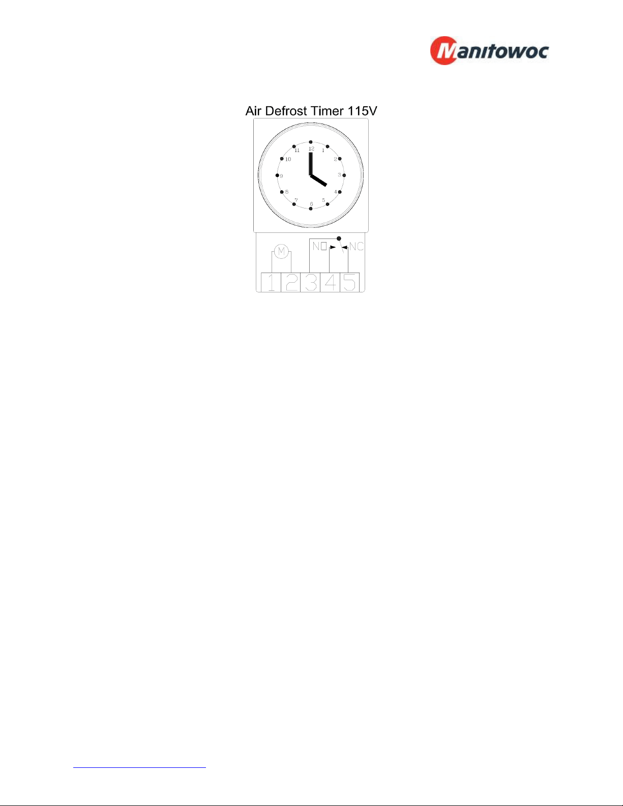
Air Defrost:
Instructions for setting the timer is located on the inside cover of the time clock. The defrost
timer clock must be set to the correct time at initial start-up and after any power interruptions.
Set the clock by rotating the clock face until the correct time is at the arrow on the face of the
timer. The switch is programmed by pushing the captive trippers to the outer ring for the entire
period the load is to be turned “ON”. When the tripper is pushed to the inside, the switch is in
the “Defrost” position. Each defrost tripper represents 15 minutes of defrost time. The timer is
factory set for four defrost cycles daily at the following times: 4:00AM, 10:00AM, 4:00PM, and
10:00PM. Each defrost cycle is programmed for 30 minutes duration. The defrost times may
be changed to initiate at periods of low activity (trippers pushed out will close contacts to
terminals 3 & 4).
Note: The timer starts the defrost cycle automatically at the predetermined times. A setting of
two to four defrost cycles per day is typical. For heavier frost loads, additional cycles may be
required.
When the defrost cycle begins:
1. Switch 3 to 4 opens in the time clock, breaking the circuit to the temperature control and
liquid line solenoid valve. This allows the compressor to pump down and shut off. Note,
the evaporator fans continue to run during the defrost cycle.
2. At the end of the defrost duration, switch contacts 3 and 4 close, energizing the
temperature control, solenoid valve circuit.
3. The suction pressure rises. When the cut-in pressure setting of the low pressure control
is reached, the compressor contactor is energized, and the compressor starts.
4. The system operates in the refrigeration cycle until the next defrost cycle is initiated by
the timer.
www.manitowocfsusa.com 800-225-9916 20
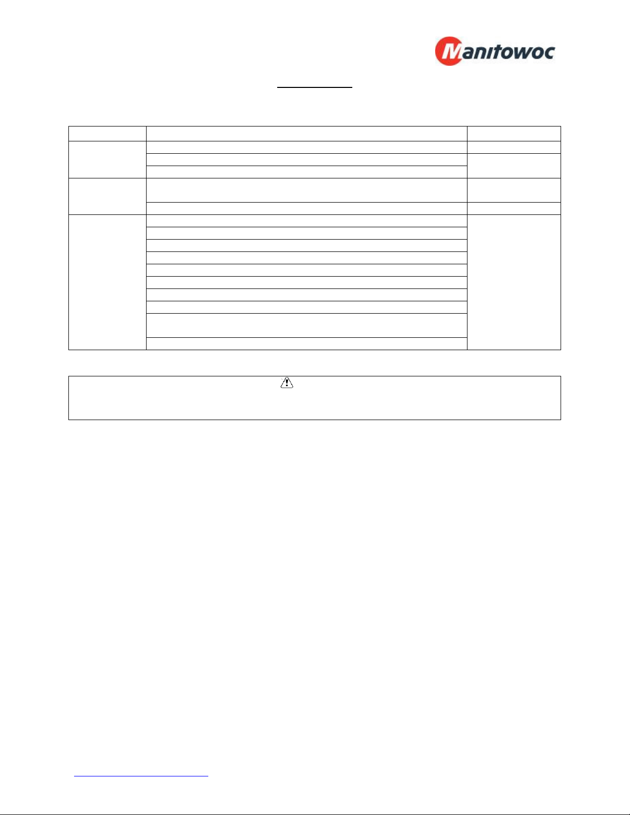
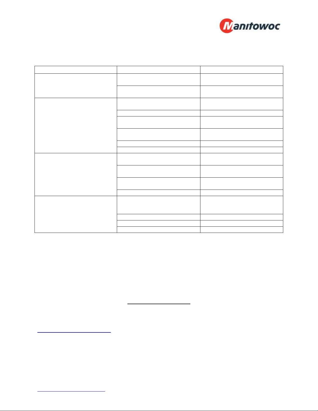
Maintenance
Maintenance Chart
Area
Task
Frequency
Evaporator Check for proper defrosting Monthly
Clean the coil and drain pan Every 6 months
Check for proper drainage
Condenser Inspect /clean the coil if the air supply is near polluting sources
(such as cooking appliances)
Monthly
Clean the coil surface Every 3 months
General Check/tighten all electrical connections Every 6 months
Check all wiring and insulators
Check contactor for proper operation and contact point deterioration
Check all fan motors
Tighten fan set screws, and motor mount nuts and bolts
For semi-hermetics, check the oil level in the system
Check the operation of the control system
Make certain all safety controls are operating properly
Check operation of the drain line heater and examine for cuts and
abrasions
Check/tighten all mechanical/flare connections
CAUTION
Failure to keep the condenser coil clean will result in reduced airflow through the
condenser, resulting in poor system performance and premature compressor failure.
Polyol Ester (POE) Lubricants:
Polyol Ester (POE) lubricants quickly absorb moisture from the ambient surroundings.
POE lubricants absorb moisture more rapidly and in greater quantity than conventional
mineral oils. Because moisture levels greater than 100 PPM will result in system
corrosion and component failure, it is essential that system exposure to ambient
conditions be kept to a minimum.
If a system is left open to the atmosphere for more than 15 minutes, the liquid line drier
and compressor oil must be replaced. Drain at least 95% of the oil from the compressor
suction port. Measure the amount of removed oil, and replace it with exactly the same
amount of new POE oil.
Mobil EAL™ ARCTIC 22 CC is the preferred Polyol Ester lubricant because of its
particular additives. ICI Emkarate RL 32S is an acceptable alternative when the Mobil
is not available. These POE lubricants must be used with HFC refrigerants. Lubricants
are packaged in specially designed, sealed containers. Once opened, use the lubricant
immediately. Properly dispose of any unused lubricant.
www.manitowocfsusa.com 800-225-9916 21
Troubleshooting Guides
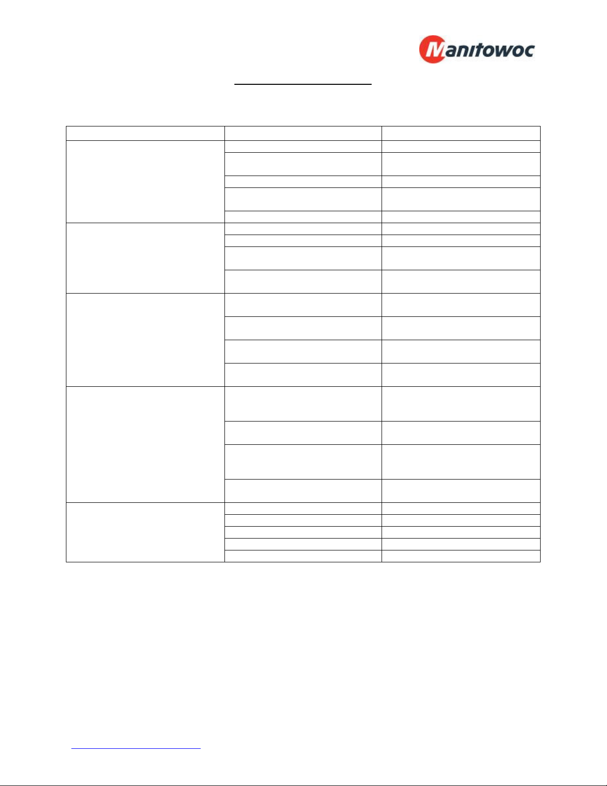
Evaporator Troubleshooting Chart:
Problem
Possible Cause
Corrective Action
Fan(s) will not operate. Main switch open Close switch
Blown fuse(s) Replace fuse(s). Check for short
circuits or overload conditions.
Defective motor Replace motor.
Defective timer or defrost
thermostat
Replace defective component.
Unit in defrost cycle Wait for completion of cycle.
Walk-in temperature too high. Thermostat set too high Adjust thermostat.
Superheat too high Adjust thermal expansion valve.
System low on refrigerant Locate and repair leak, recover,
evacuate and recharge.
Coil iced up Manually defrost coil. Check
defrost controls.
Ice accumulating on ceiling
around evaporator and/or on fan
guards, venturi, or blades.
Defrost duration is too long Adjust defrost termination
thermostat (if adjustable).
Fan delay not delaying fans after
defrost period
Replace defective defrost
thermostat.
Defective defrost thermostat or
timer
Replace defective component.
Too many defrost cycles per day Reduce number of defrost cycles
per day.
Frost on coil after defrost cycle. Coil temperature not getting
above freezing point during
defrost
Check heater operation
Not enough defrost cycles per
day
Adjust timer for more defrost
cycles per day
Defrost cycle too short Adjust timer for longer cycle,
check defrost thermostat
mounting
Defective timer or defrost
thermostat
Replace defective component.
Ice accumulating in drain pan. Defective heater Replace heater.
Unit not pitched properly Check and adjust.
Drain line plugged Clean drain line.
Defective drain line heater Replace heater.
Defective timer or thermostat Replace defective component.
www.manitowocfsusa.com 800-225-9916 22
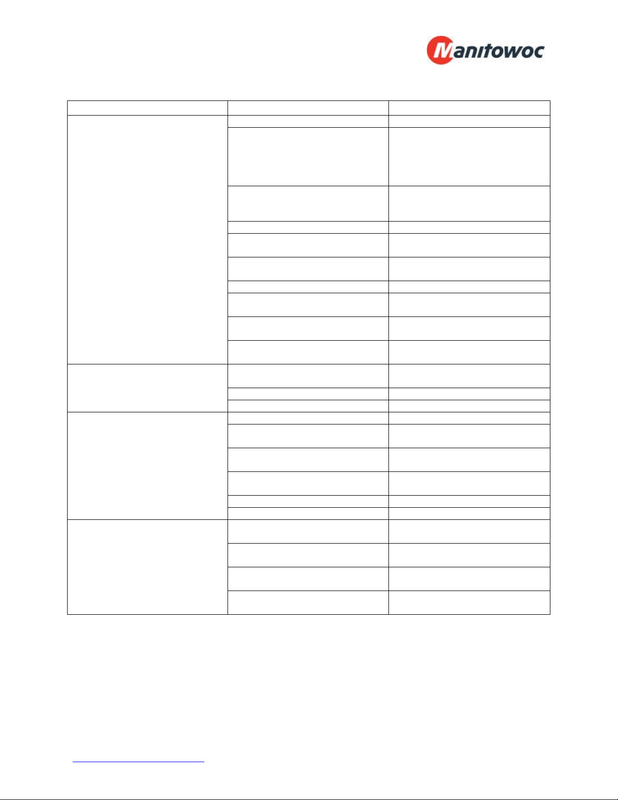
Condensing Unit Troubleshooting Chart:
Problem
Possible Cause
Corrective Action
Compressor will not run. Main switch open Close switch
Fuse blown Check electrical circuits and
motor winding for shorts or
grounds. Investigate for possible
overloading. Replace fuse after
fault is corrected.
Thermal overloads tripped Overloads are automatically
reset. Check unit closely when
unit comes back on line.
Defective contactor or coil Repair or replace
System shut down by safety
devices
Determine type and cause of
shutdown and correct
No cooling required None. Wait until cooling is
required.
Liquid line solenoid will not open. Repair or replace coil.
Low pressure switch will not
close.
Replace switch
Motor electrical trouble Check motor for open windings
or short circuit.
Loose wiring Check all wire junctions. Tighten
all terminal screws.
Compressor noisy or vibrating Flooding of refrigerant into
crankcase
Check superheat setting of
expansion valve
Improper pipe support Relocate or add hangers
Worn compressor Replace compressor
High discharge pressure Non-condensable in system Recover, evacuate and charge
System overcharged with
refrigerant
Remove excess charge
Discharge shut-off valve partially
closed
Open valve
Fan not running Check electrical circuit or replace
defective fan motor
Insufficient condenser air supply Check for cause and correct
Dirty condenser coil Clean coil
Low discharge pressure Faulty head pressure control Check head pressure control
operation.
Suction shut-off valve partially
closed
Open valve
Insufficient refrigerant in system Locate and repair leak, recover,
evacuate and recharge
Low suction pressure See “Low Suction Pressure”
page 3-8.
www.manitowocfsusa.com 800-225-9916 23
Condensing Unit Troubleshooting Chart (continued):
Problem
Possible Cause
Corrective Action
High suction pressure Excessive load Reduce load or add additional
equipment
Expansion valve overfeeding Secure and insulate TXV bulb or
if required adjust superheat.
Low suction pressure Lack of refrigerant Locate and repair leak, recover,
evacuate and charge.
Evaporator dirty or iced Clean
Clogged liquid line or suction line
filter-drier
Replace filter-drier
Expansion valve malfunctioning Check and reset for proper
superheat
Condensing temperature too low Check head pressure control
Improper TXV Check for proper sizing
Compressor loses oil Lack of refrigerant Locate and repair leak, recover,
evacuate and recharge
Excessive compression ring
blow-by
Replace compressor
Refrigerant flood back Maintain proper superheat at
compressor
Improper piping or traps Correct piping
Compressor thermal protector
switch open
Operating beyond design Add facilities so that operating
conditions are within allowable
limits
Discharge valve partially shut Open valve
Dirty condenser coil Clean coil
Overcharged system Correct charge
Notes:
Warranty Information
For information regarding warranty guidelines, claim form, product registration, warranty
verification, or locating a service provider please visit our website at
www.manitowocfsusa.com or call 1-800-225-9916.

www.manitowocfsusa.com 800-225-9916 24
System Start-Up Data Sheet
A permanent data sheet must be prepared on each installation. A completed copy should be retained
with this manual.
System Reference Data
The following information should be filled out and signed by Refrigeration Installation Contractor:
Date System Installed: / /
Installer and Address:
Phone Number: ( ) -
Service Agency:
Phone Number: ( ) -
Condensing Unit: Model Number:
Serial Number:
Compressor Model Number: Compressor Model Number:
Compressor Serial Number: Compressor Serial Number:
Electrical: Volts: Phase:
Voltage at Compressor: L1: L2: L3:
Amperage at Compressor: L1: L2: L3:
Evaporator(s): Quantity:
Evaporator Model Number: Evaporator Model Number:
Evaporator Serial Number: Evaporator Serial Number:
Electrical: Volts: Phase:
Expansion Valve Manufacturer/Model Number:
Ambient at Start-Up: °F
Design Box Temperature: °F °F
Operating Box Temperature: °F °F
Thermostat Setting: °F °F
Defrost Settings: /day minutes failsafe /day minutes failsafe
Compressor Discharge Pressure: PSIG PSIG
Compressor Suction Pressure: PSIG PSIG
Suction Line Temperature at Compressor: °F °F
Discharge Line Temperature at Compressor: °F °F
Superheat at Compressor: °F °F
Suction Line Temperature at Evaporator: °F °F
Superheat at Evaporator: °F °F
Evacuation: # Times Final Micron # Times Final Micron
Evaporator Drain Line Trapped Outside of Box: Yes No
www.manitowocfsusa.com 800-225-9916 25
Wiring Diagrams
www.manitowocfsusa.com 800-225-9916 26
www.manitowocfsusa.com 800-225-9916 27
www.manitowocfsusa.com 800-225-9916 28
www.manitowocfsusa.com 800-225-9916 29
www.manitowocfsusa.com 800-225-9916 30
www.manitowocfsusa.com 800-225-9916 31
www.manitowocfsusa.com 800-225-9916 32
www.manitowocfsusa.com 800-225-9916 33
www.manitowocfsusa.com 800-225-9916 34
www.manitowocfsusa.com 800-225-9916 35
www.manitowocfsusa.com 800-225-9916 36
www.manitowocfsusa.com 800-225-9916 37