User Manual

User Manual
GENERAL INFORMATION
SRX900 Series - User Manual
Document Number: 1000365021
Version: A-EN
Distribution Date: May 10, 2022
Copyright © 2022 by HARMAN International; all rights reserved
JBL PROFESSIONAL
8500 Balboa Blvd
Northridge, CA 91329
USA

User Manual
TABLE OF CONTENTS
1 - SAFETY .................................................................................................5
1.1 Safety Instructions ....................................................................................5
1.2 General Hardware Information ..........................................................................5
1.3 Attachment to Structures ...............................................................................5
1.4 Important Safety Warning ..............................................................................5
1.5 Are You New to Rigging? ..............................................................................6
1.6 Inspection and Maintenance ............................................................................6
1.7 Symbols ............................................................................................7
1.8 Resources and Documentation ..........................................................................7
2 - SYSTEM COMPONENTS ..................................................................................8
3 - COMPATIBLE ACCESSORIES ...............................................................................9
4 - SOFTWARE OVERVIEW ...................................................................................11
4.1 Line Array Calculator 3
TM
.............................................................................11
4.2 Array Link
TM
.......................................................................................11
4.3 Performance
TM
......................................................................................11
5 - SRX900 SERIES .........................................................................................12
6 - AMPLIFIER MODULES ...................................................................................13
6.1 SRX906LA and SRX910LA Rear Panel ...................................................................13
6.2 SRX918S and SRX928S Rear Panel .....................................................................14
7 - DSP OVERVIEW .........................................................................................15
8 - AC POWER .............................................................................................16
8.1 AC Voltage Requirements .............................................................................16
8.2 Power Connectors ...................................................................................16
8.3 Current Draw ....................................................................................17
8.4 Power States .......................................................................................17
8.5 Power LED ........................................................................................17
9 - AUDIO CONNECTIVITY ...................................................................................18
9.1 Rear Panel Audio LEDs ...............................................................................18
9.2 Example: Small System Audio Wiring ....................................................................19
9.3 Example: Large System Audio Wiring ....................................................................19
10- NETWORKING ..........................................................................................20
10.1 IP Addresses ......................................................................................20
10.2 Subnet Mask ......................................................................................20
10.3 Network Configuration for SRX900 Devices ..............................................................20
10.4 Ethernet Ports .....................................................................................21

User Manual
10.5 Network Topologies .................................................................................21
11 - HCONTROL ............................................................................................23
11.1 HControl ID ........................................................................................23
11.2 HCID Use Cases . . . . . . . . . . . . . . . . . . . . . . . . . . . . . . . . . . . . . . . . . . . . . . . . . . . . . . . . . . . . . . . . . . . . . . . . . . . . . . . . . . . . 23
11.3 Example System HCID Addressing .....................................................................23
12 - SPEAKER PRESETS ....................................................................................24
12.1 Line Array Modes ...................................................................................24
12.2 Subwoofer Presets ..................................................................................24
12.3 SRX906LA Preset Examples ..........................................................................25
12.4 SRX910LA Preset Examples ..........................................................................25
13 - ARRAY CALIBRATION . . . . . . . . . . . . . . . . . . . . . . . . . . . . . . . . . . . . . . . . . . . . . . . . . . . . . . . . . . . . . . . . . . . . . . . . . . . . . . . . . . . 26
13.1 Filter 1- Array Size Compensation (ASC) .................................................................26
13.2 Filter 2 - Throw Distance Compensation (TDC) ............................................................26
13.3 Array Calibration Filter Example ........................................................................27
14 - SUBWOOFERS ........................................................................................28
14.1 Cardioid Subwoofers ................................................................................28
14.2 Recommended Cardioid Setups .......................................................................28
14.3 Minimum Space Between Cardioid Stacks ...............................................................29
14.4 Subwoofer Ratios ...................................................................................29
15 - LCD ..................................................................................................30
15.1 Overview Screens ...................................................................................30
15.2 DSP .............................................................................................30
15.3 Network ..........................................................................................32
15.4 HControl ..........................................................................................33
15.5 Settings ..........................................................................................33
15.6 Info ..............................................................................................34
15.7 System Reset ......................................................................................35
15.8 Menu Overview .....................................................................................36
15.9 Revert Firmware ....................................................................................37
16 - SRX900 RC RAIN COVER ................................................................................38
17 - PRODUCT SPECIFICATIONS .............................................................................39
18 - REGULATORY SPECIFICATIONS ..........................................................................47
19 - DIMENSIONS ..........................................................................................48
20 - CONTACT INFORMATION ................................................................................50

User Manual
5
1 - SAFETY
1.1 SAFETY INSTRUCTIONS
1. Read these instructions.
2. Keep these instructions.
3. Heed all warnings.
4. Follow all instructions.
5. Do not expose the product to direct rain or sea spray.
6. Clean only with a dry cloth.
7. Do not install near any heat sources such as radiators, heat registers, stoves, or other apparatus that produce heat.
8. Only use attachments/accessories specified by the manufacturer.
9. Use only with a cart, stand, tripod, bracket, or table specified by the manufacturer or sold with the apparatus. When a cart is used,
use caution when moving the cart/apparatus combination to avoid injury from tip-over.
10. Refer all servicing to qualified service personnel. Servicing is required when the apparatus has been damaged in any way, such as if
liquid has been spilled or objects have fallen into the apparatus, or if the apparatus has been exposed to rain or moisture, does not
operate normally, or has been dropped.
11. Contact JBL Professional for advanced servicing issues.
12. CAUTION - DO NOT PERFORM ANY SERVICING UNLESS YOU ARE QUALIFIED TO DO SO.
13. Prolonged exposure to excessive SPL can cause hearing damage. The loudspeaker is easily capable of generating sound pressure
levels (SPL) sufficient to cause permanent hearing damage to performers, production crew, and audience members. Caution should
be taken to avoid prolonged exposure to SPL in excess of 90 dB.
14. Read the SRX900 Series Rigging Manual before installation and use of the product.
1.2 GENERAL HARDWARE INFORMATION
Any hardware used in an overhead suspension application must be load rated for the intended use. Generally, this type of hardware
is available from rigging supply houses, industrial supply catalogs, and specialized rigging distributors. Local hardware stores do not
usually stock these products. Compliant hardware will be referenced with a working load limit (WLL) and a traceability code.
1.3 ATTACHMENT TO STRUCTURES
A licensed Professional Engineer must approve the placement and method of attachment to the structure prior to the installation of any
overhead object. The following performance standards should be provided to the Professional Engineer for design purposes: Uniform
Building Code as applicable, Municipal Building Code as applicable, and Seismic Code as applicable. The installation of the hardware
and method of attachment must be carried out in the manner specified by the Professional Engineer. Improper installation may result in
damage, injury, or death.
1.4 IMPORTANT SAFETY WARNING
The information in this section has been assembled from recognized engineering data and is intended for informational purposes only.
None of the information in this section should be used without first obtaining competent advice with respect to applicability to a given

User Manual
6
1.5 ARE YOU NEW TO RIGGING?
If you are new to rigging, you should:
• Know the rules for safe rigging.
• Attend a safe rigging seminar.
• Meet and establish a relationship with a licensed mechanical or structural engineer. Get in the habit of asking them questions in-
stead of assuming their answers. Learn from what they tell you.
• Research and understand the codes, practices, and requirements of the venues where you intend to operate your sound system.
1.6 INSPECTION AND MAINTENANCE
Suspension systems are comprised of mechanical devices and, as such, require regular inspection and routine maintenance to ensure
proper functionality. Before suspending or pole mounting any speaker system, always inspect all components (enclosure, suspen-
sion frames or brackets, pins, eye bolts, etc.) for cracks, deformations, corrosion, or missing/loose/damaged parts that could reduce
strength and safety of the array. Do not suspend or pole mount a speaker until the proper corrective action has been taken.
Installed systems should be inspected at least once a year. The inspection must include a visual survey of all corners and load-bearing
surfaces for signs of cracking, water damage, delamination, or any other condition that may decrease the strength of the loudspeaker
enclosure.
Accessory suspension hardware provided with or for SRX900 systems must be inspected for fatigue at least once a year or as required
by local ordinance. The inspection must include a visual survey of the material for signs of corrosion, bending, or any other condition that
may decrease the strength of the fastener. Additionally, any eyebolts must be checked for possible spin-out of the enclosure.
For all other hardware and fittings, refer to the hardware manufacturer’s inspection and maintenance guidelines for process.
JBL is not responsible for the application of its products for any purpose or the misuse of this information for any purpose. Furthermore,
JBL is not responsible for the abuse of its products caused by avoiding compliance with inspection and maintenance procedures or
any other abuse.
Prior to suspending the system, an expert, trained and experienced in suspending speaker systems, should inspect all parts and com-
ponents.
circumstance. None of the information presented herein is intended as a representation or warranty on the part of JBL. Anyone making
use of this information assumes all liability arising from such use.
All information presented herein is based upon materials and practices common to North America and may not directly apply to other
countries because of differing material dimensions, specifications, and/or local regulations. Users in other countries should consult with
appropriate engineering and regulatory authorities for specific guidelines.
Correct use of all included hardware is required for secure system suspension. Careful calculations should always be performed to
ensure that all components are used within their working load limits before the array is suspended. Never exceed the maximum recom-
mended load ratings.
Before suspending any speaker system, always inspect all components (enclosure, rigging frames, pins, eye bolts, track fittings, etc.)
for cracks, deformations, corrosion, or missing/loose/damaged parts that could reduce strength and safety of the array. Do not suspend
the speaker until the proper corrective action has been taken. Use only load-rated hardware when suspending JBL suspendable loud-
speaker models.
User Manual
7
1.7 SYMBOLS
The following symbols are used in this document:
CAUTION: This symbol gives notice of a potential risk of harm to the individual or the equipment. Instructions
marked with this symbol must be strictly followed.
TIP: This symbol gives notice of helpful, relevant information about the topic.
INSTRUCTIONS: This symbol gives notice of instructions that must be followed for proper installation and use of
the product.
TOOLS REQUIRED: This symbol gives notice of tools that must be used for proper installation and use of the
product.
TIPPING HAZARD: This symbol gives notice of potential tip hazard. Use caution when moving the cart/apparatus
combination to avoid injury from tip-over.
USER MANUAL: This document focuses on the electromechanical aspects of the system, including amplification, wiring, speaker pre-
sets, tuning, and optimization. User manuals do not include information regarding rigging and suspension hardware.
RIGGING MANUAL: This document focuses on the mechanical aspects of the system, including step-by-step rigging instructions, ac-
cessory usage, mechanical limits, and safety instructions. All users must read this document.
SPECIFICATION SHEETS: These documents include detailed specifications for loudspeakers and accessories. Specifications include
acoustical performance, material types, weight, and general mechanical information. Specification sheets are available for each SKU.
CUSTOMER DRAWINGS: This is a collection of files that include detailed drawings for each SKU. The collection consists of detailed
dimensional 2D PDF/DXF documents and simplified 3D DXF models. Depending on the product, additional types of 3D files might be
available for download at www.jblpro.com.
VIDEO TUTORIALS: Software and hardware video tutorials are available for watching on the JBL Professional YouTube channel.
1.8 RESOURCES AND DOCUMENTATION
Several resources are available to SRX900 Series owners to illustrate proper and safe use of the equipment. Below is an overview of
what is available and a brief description of each resource:
User Manual
8
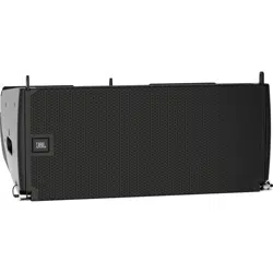
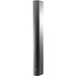
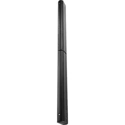
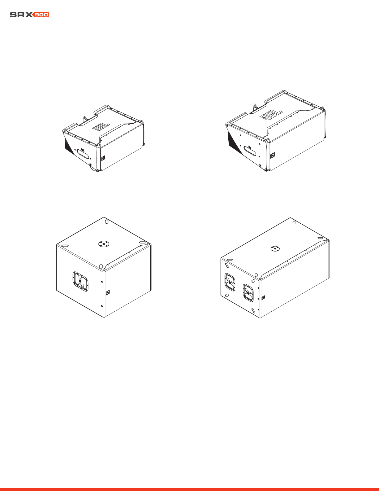
2 - SYSTEM COMPONENTS
SRX906LA | Line Array Element SRX910LA | Line Array Element
SRX918S | Subwoofer SRX928S | Subwoofer
User Manual
9
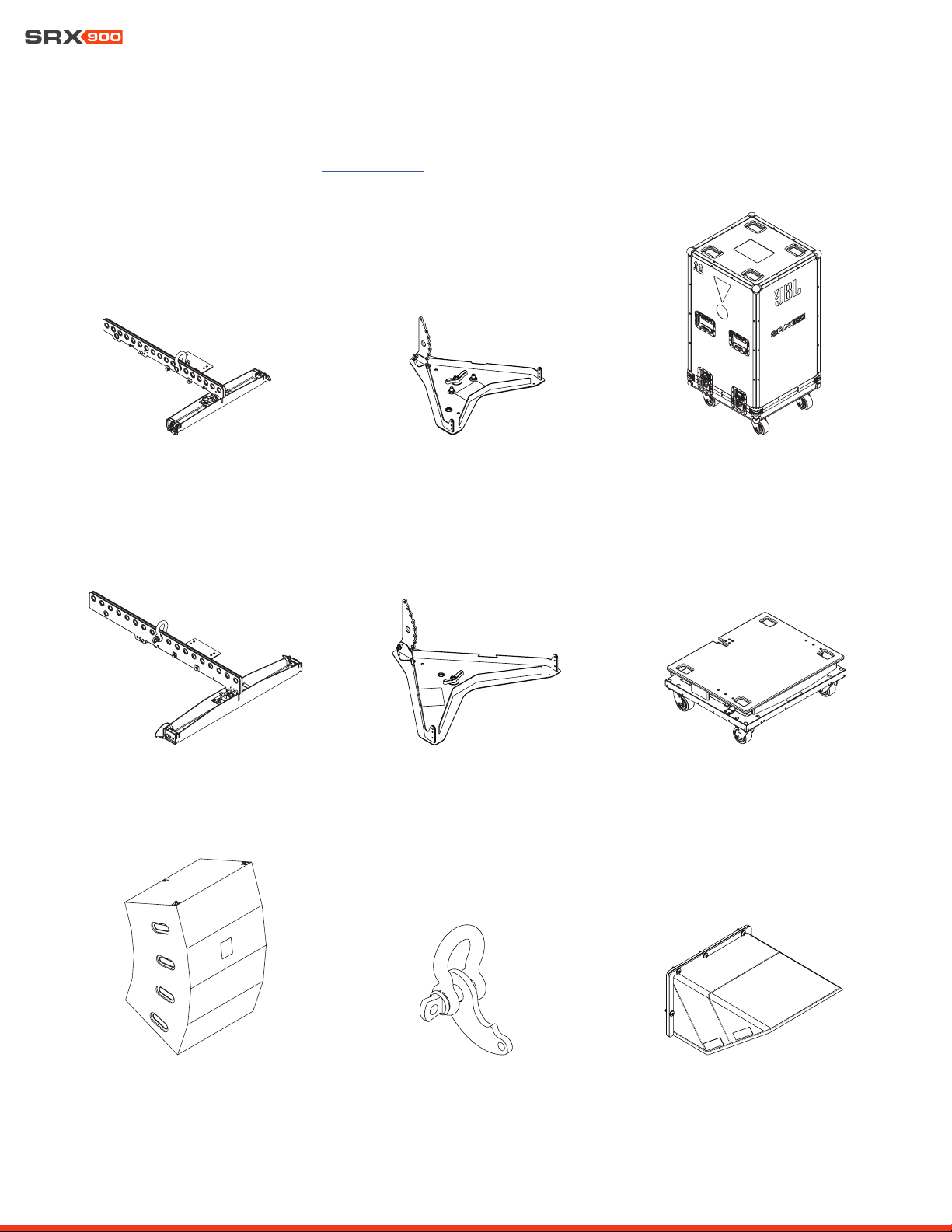
3 - COMPATIBLE ACCESSORIES
All listed accessories are compatible with SRX900 Series products. For more information on the accessories and use cases refer to the
SRX900 Series Rigging Manual found at www.jblpro.com.
SRX906LA CASE
SRX910LA VT | Vertical Transporter
SRX910LA BP | Base Plate
SRX900LA PB | Pull Back SRX900 RC1 | Rain Cover
SRX906LA BP | Base Plate
SRX906LA AF | Array Frame
SRX910LA VT CVR | Cover
SRX910LA AF | Array Frame
User Manual
10
TIP: For rigging-specific instructions, refer to the SRX900 Series Rigging Manual found at www.JBLpro.com.
CAUTION: Always use components and accessories specified and approved by JBL Professional. When a cart is
used, use caution when moving the cart to avoid injury from tip-over.
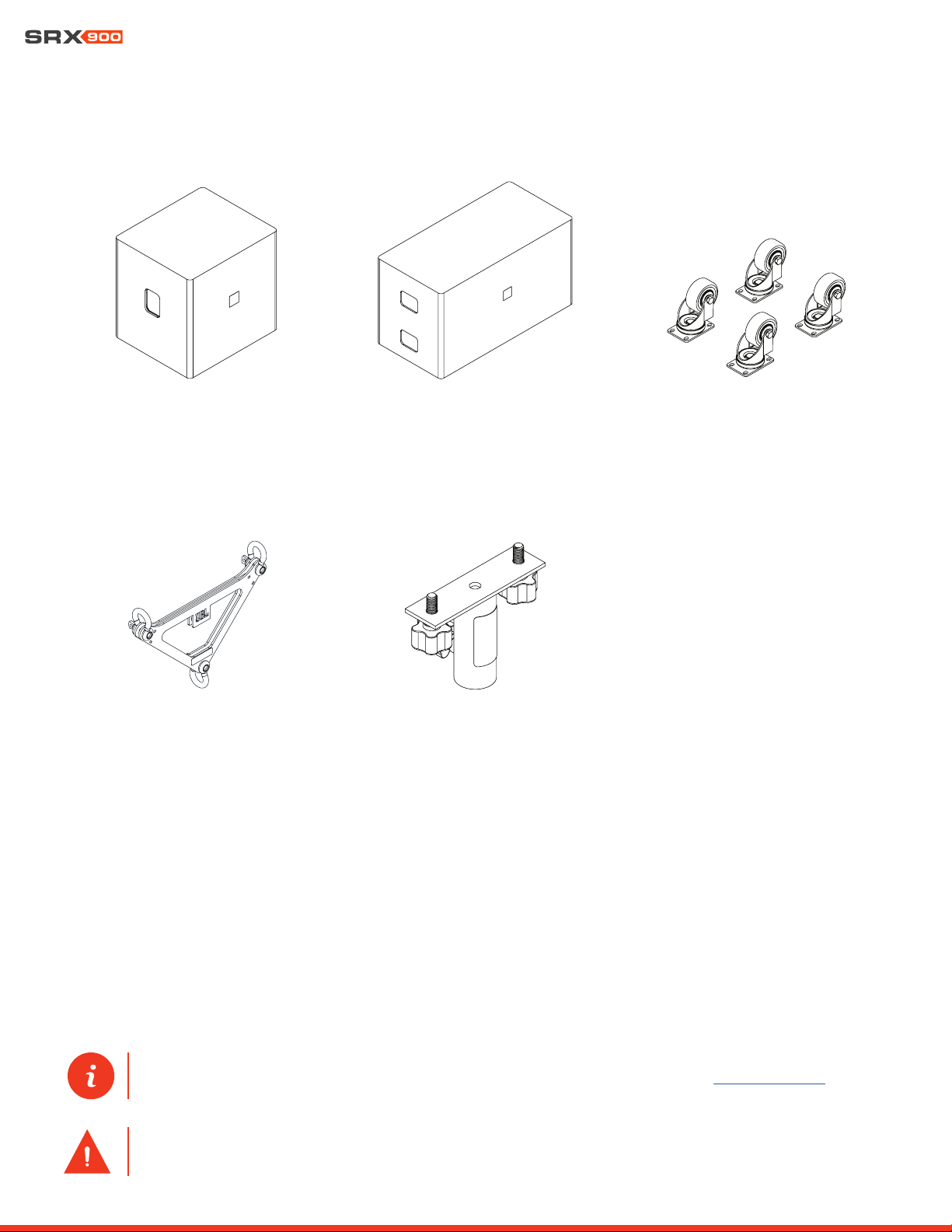
ACK1 | Accessory Caster Kit
VTX PM T | Pole Mount Adapter T-Style
SRX928S CVR | Padded CoverSRX918S CVR | Padded Cover
VTX DELTA | Delta Plate
User Manual
11
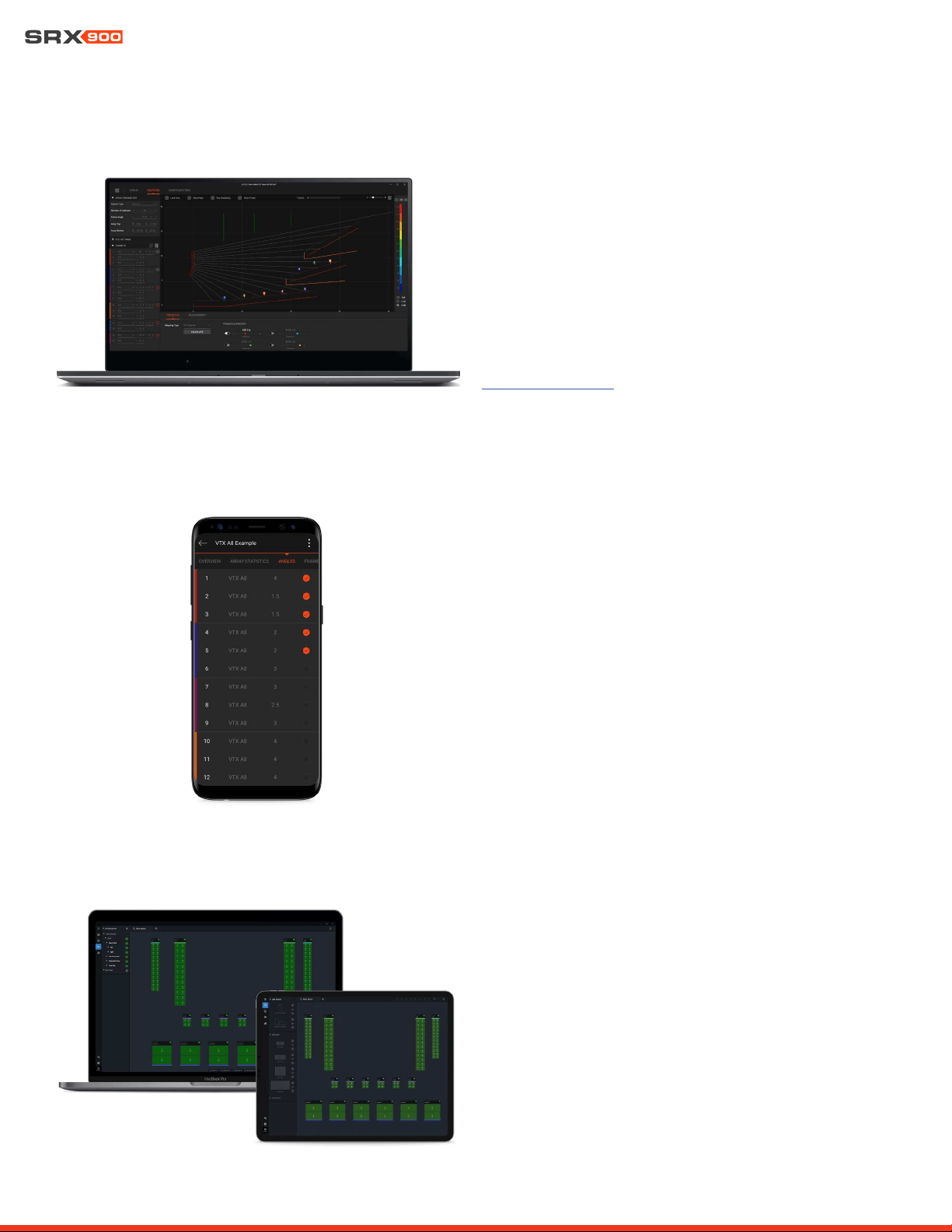
4 - SOFTWARE OVERVIEW
4.1 LINE ARRAY CALCULATOR 3
TM
LAC-3 is simulation software for designing and predicting the
acoustical performance of JBL line array systems, such as the
SRX900 Series, as well as flown and ground-stacked subwoofer
arrays. Subwoofer delay values can be generated for electronic
delay steering (EDS) using the built-in coverage calculator. LAC-
3 also performs mechanical validation of rigging hardware, calcu-
lates weight limits, and generates safety warnings.
www.jblpro.com/lac3
4.2 ARRAY LINK
TM
Array Link
TM
is a mobile companion app that works in conjunction
with LAC-3 software to assist in deployment of SRX900 systems.
Array Link uses a QR code system to transfer all mechanical array
information from the main LAC-3 application to a mobile phone.
All relevant rigging and mechanical options are presented in an
easy-to-understand layout. The application is compatible with
iOS® and Android
TM
and can be obtained from their respective
app stores.
4.3 PERFORMANCE
TM
JBL Performance is the configuration and control application for
networked SRX900 Series systems. The user interface guides the
user through the complete system design, configuration, and con-
trol process with a thoughtful and visual workflow. A dedicated
show mode provides all monitoring and control functions needed
to deliver a complete picture of the system’s performance in real
time..
User Manual
12
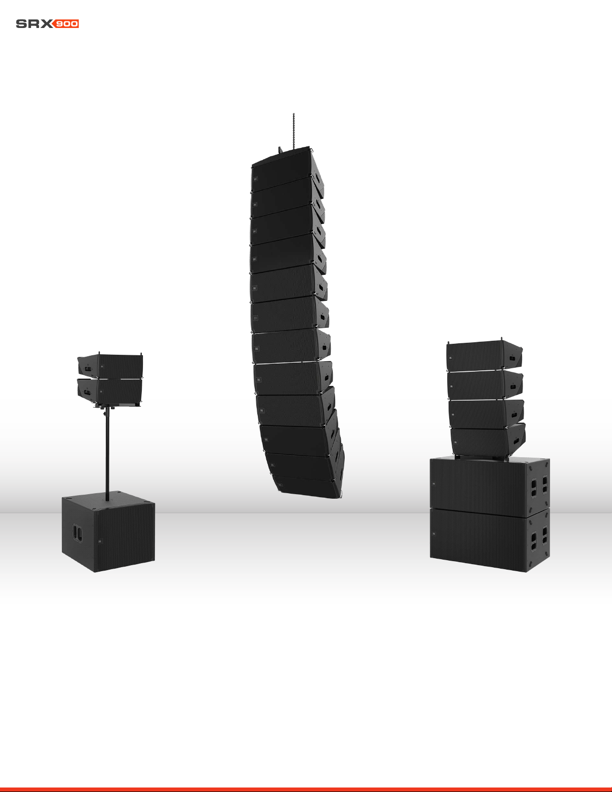
5 - SRX900 SERIES
Thank you for purchasing SRX900 Series products!
The SRX900 Series is a high performance powered loudspeaker system comprising two full-range line array elements and two subwoof-
ers. The SRX900 Series boasts an array of premium features that make it the best system solution in its class. Drawing on JBL’s long
history of groundbreaking technology and innovative loudspeaker design, the SRX900 Series meets the needs of any application where
high performance, comprehensive control, and legendary JBL sound are required. Each speaker was purposefully designed and thought
through with full consideration for its intended use. Each accessory is carefully designed to achieve a complete and perfectly cohesive
system that is both powerful, lightweight, and easy to use. All models integrate Class-D amplification, premium digital signal processing,
including speaker presets compatible with our flagship touring systems. Now, local production houses and smaller to medium-sized
installations can deploy a no-compromise, affordable solution configurable as ground stacked, pole mounted, or fully flyable with the
SRX900’s integrated three-point rigging system and suspension accessories.
User Manual
13
6 - AMPLIFIER MODULES
SRX900 products include a Class-D amplifier with built-in DSP providing optimum performance and a plug and play, easy-to-use experi-
ence. All speaker processing is performed using the internal processing, which includes the advanced LevelMax
TM
limiter suite, ensuring
proper, reliable operation under any conditions. The SRX900 Series DSP also offers a user-adjustable input section for equalization,
time alignment, and level adjustments. An LCD screen allows easy access to critical functions, including selecting operating modes,
adjusting networking parameters, and basic DSP access. Two Ethernet ports utilize Harman’s HControl protocol for external control
using standard off-the-shelf Ethernet and WiFi equipment.
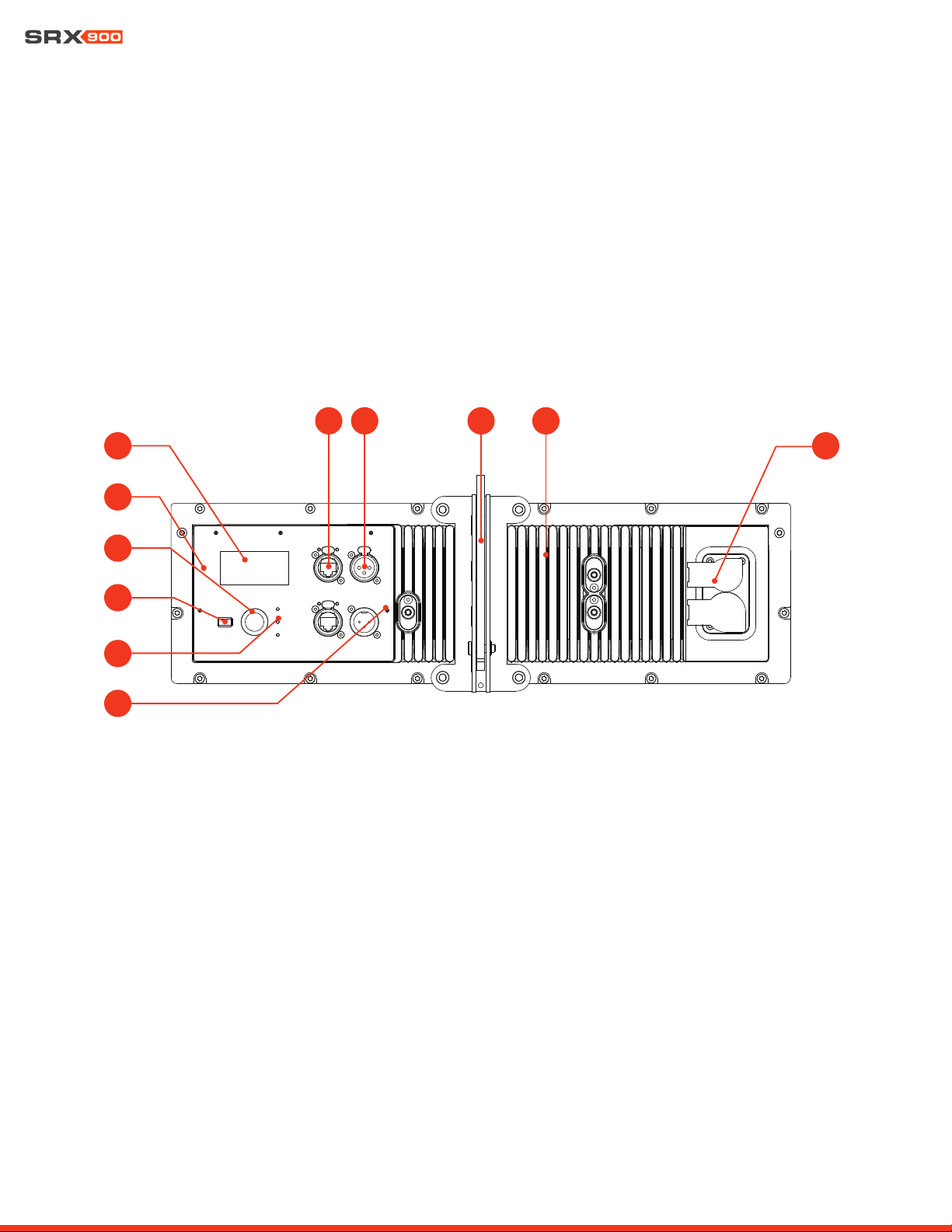
6.1 SRX906LA AND SRX910LA REAR PANEL
The SRX906LA and SRX910LA share the same rear panel layout and features. The illustrations and descriptions below apply to both
models.
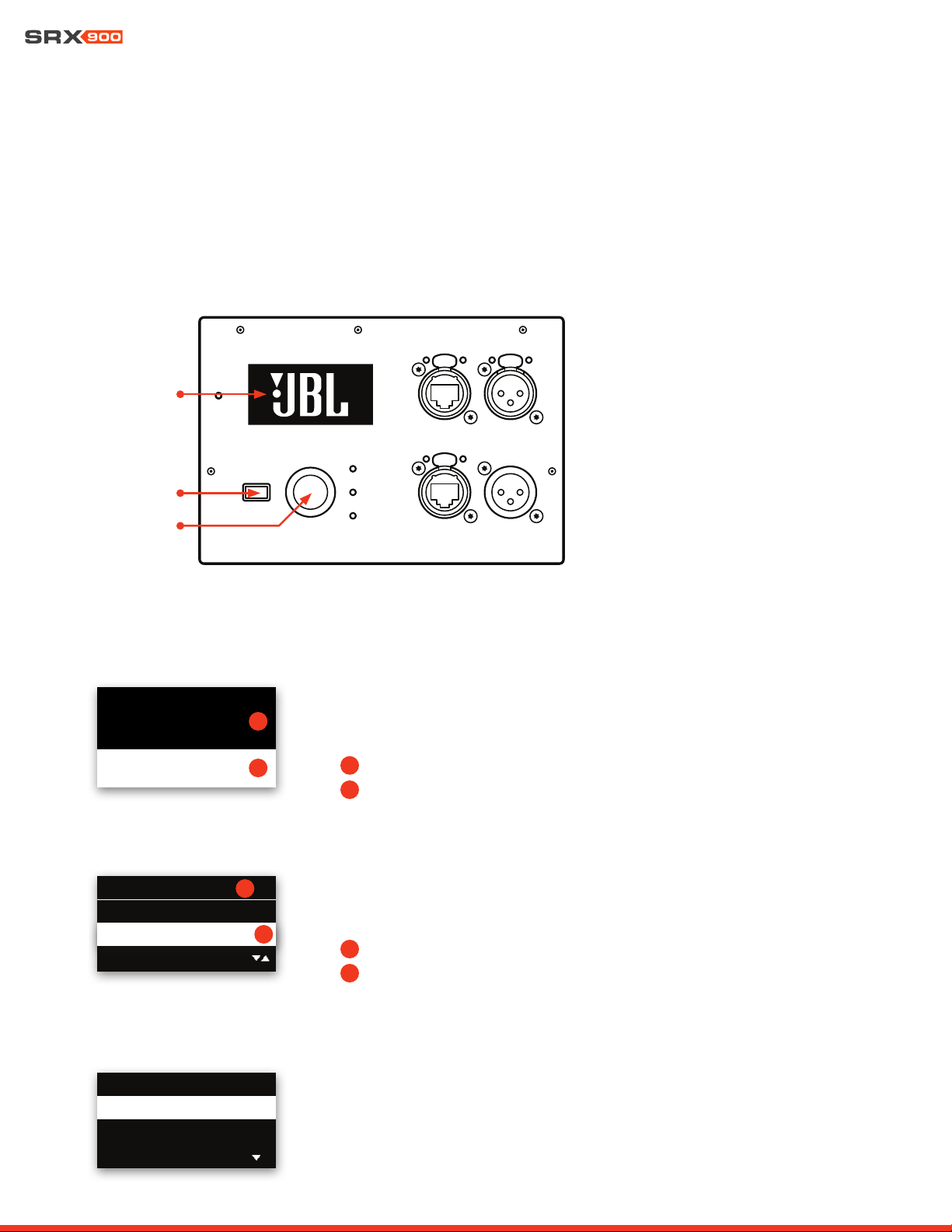
1 - LCD Screen: Allows users to access speaker operating modes, DSP parameters, networking settings, and much more. Controlled
with the Encoder and the Back button. Refer to Section 15-LCD for more information on navigation and additional details on func-
tionality.
2 - Locate LED: Software-controlled LED for speaker identification. The speaker can be set to Locate mode via JBL Performance
software or from the LCD, for bidirectional visual identification of speaker. This is especially useful during setup, when physical speak-
ers are matched with software equivalents.
3 - Encoder: Controls the LCD menus and the master volume of the unit. Turn the knob to navigate through the menus. Press the
encoder to confirm an action or enter a menu. Refer to Section 15-LCD for more information on using the encoder to control the LCD
screen.
4 - Back Button: Used in conjunction with the encoder to control the LCD screen.
5 - Signal/Limit/Power LED: These three LEDs provide visual feedback for critical speaker parameters, including power state, signal,
and limiting and fault conditions. For additional information on LED functionality refer to Section 8.5 - Power LED and Section 9.1 -
Rear Panel Audio LEDs.
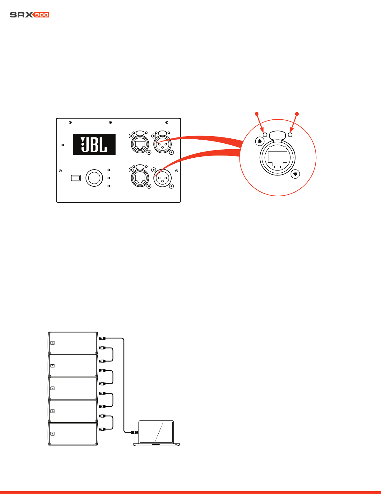
6 - etherCON Connectors: Allow use of standard Ethernet cable to network multiple units and control the system. An internal Ether-
net switch connects the two connectors together. Either connector can be used as the input or output. For more information on the
1
2
4
3
5
6 7 8 9
10
11
User Manual
14
connectors, refer to Section 10-Networking
7 - XLR Connectors: Input and output balanced XLR connectors for audio connectivity. The input connector passes signal directly
from the input to the output, bypassing DSP for zero latency. The output connector continues to function even under power loss.
8 - Rigging Link Bar: Adjustable central rigging bar for connecting cabinets together and selecting angles. For more information refer
to the SRX900 Rigging Manual.
9 - Amplifier Heatsink: Aluminum fins for cooling the SRX900 internal amplifier. No external fans are used for cooling the amplifiers.
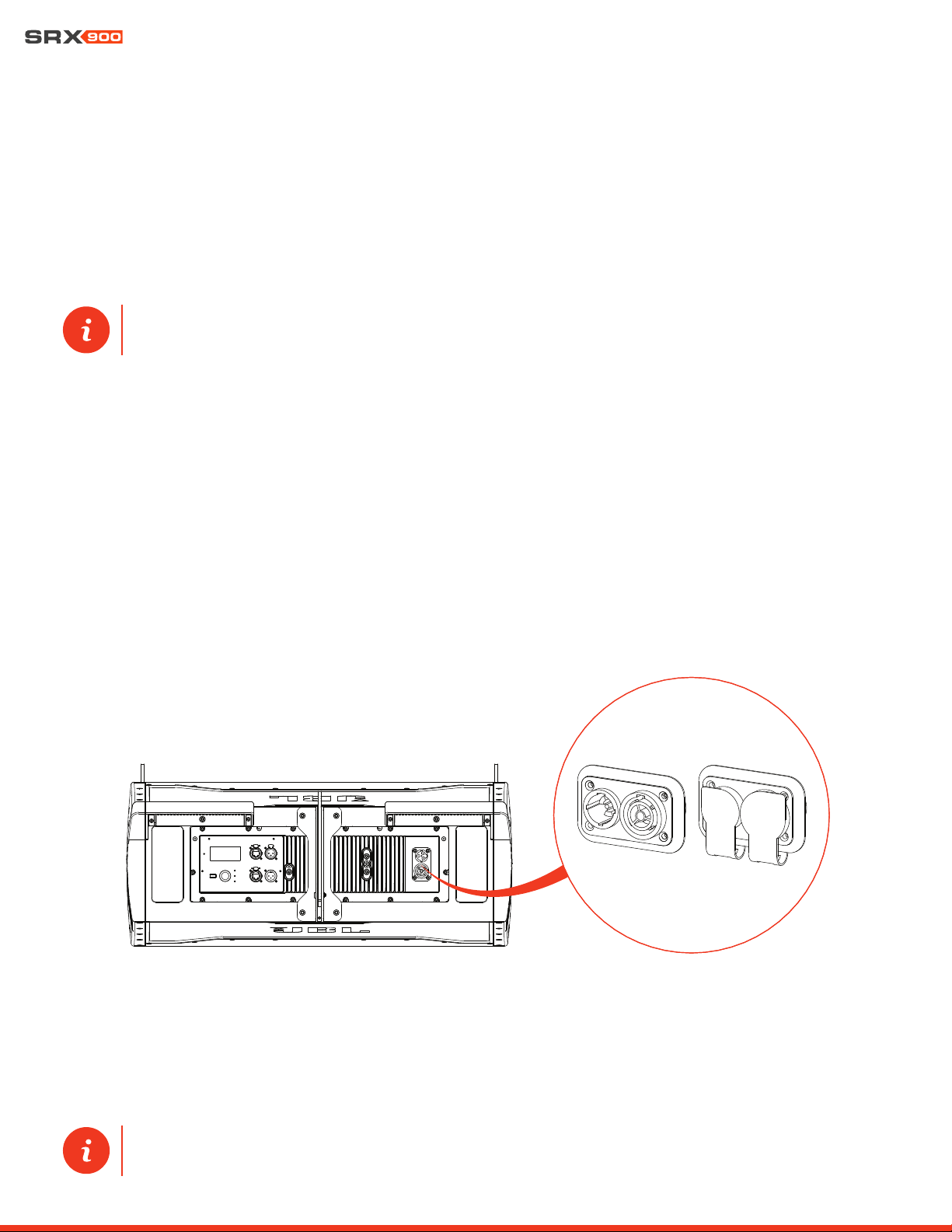
10 - Power Connectors: Neutrik powerCON TRUE1® TOP (True Outdoor Protection) connectors for power connectivity. These rugge-
dized sealed connectors feature an IP65 rating as well as UL 50E certification for UV resistance. The input connector is used to supply
power but also serves as the mains ON/OFF switch. The output connector can be used to connect multiple units together. Refer to
Section 9-Power for additional information on power connectivity and requirements.
10 - Mount Point for SRX900RC Rain Cover: Six M6 mounting points for attaching the SRX900 RC Rain Cover. The cover protects
the screen, controls, and connectors from moisture. Refer to Section 16 - Rain Cover for more information.
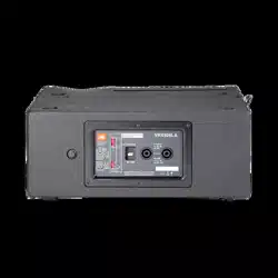
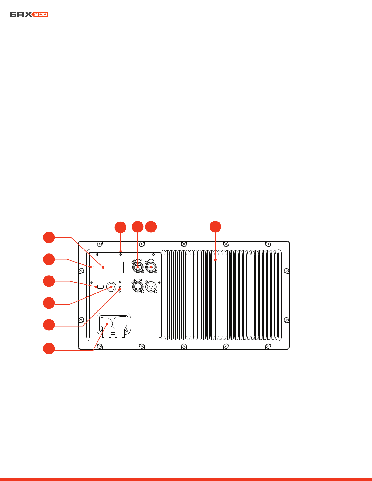
6.2 SRX918S AND SRX928S REAR PANEL
The SRX918S and SRX928S share the same rear panel layout and features. The illustrations and description below apply to both models.
1
2
4
3
5
7 8 9
6
10
1 - LCD Screen: Allows users to access speaker operating modes, DSP parameters, networking settings, and much more. Controlled
with the Encoder and the Back button. Refer to Section 15-LCD for more information on navigation and additional details on func-
tionality.
2 - Locate LED: Software-controlled LED for speaker identification. The speaker can be set to Locate mode via JBL Performance
software or from the LCD, to bi-directionally visually identify the speaker. This is especially useful during setup, when physical speak-
ers are matched with software equivalents.
3 - Encoder: Controls the LCD menus and master volume of the unit. Turn the knob to navigate through the menus. Press the encod-
er to confirm an action or enter a menu. Refer to Section 15 - LCD for more information on using the Encoder to control LCD screen.
User Manual
15
4 - Back Button: Used in conjunction with the Encoder to control the LCD Screen.
5 - Signal / Limit / Power LED: These three LEDs provide visual feedback for critical speaker parameters, including power state,
signal, and limiting and fault conditions. For additional information on LED functionality refer to Section 8.5 - Power LED and Section
9.1 - Rear Panel Audio LEDs.
6 - Mount Point for SRX900RC Rain Cover: Six M6 mounting points for attaching the SRX900RC Rain Cover. The cover protects the
screen, controls, and connectors from moisture. Refer to Section 16 - Rain Cover for more information.
7 - EtherCon Connectors: Allows use of a standard Ethernet cable to network multiple units and control the system. An internal Eth-
ernet switch connects the two connectors together. Either connector can be used as the input or output. For more information no the
connectors refer to Section 10-Networking.
8 - XLR Connectors: Input and output balanced XLR connectors for audio connectivity. The input connector passes signal directly
from the input to the output, bypassing DSP for zero latency. The output connector continues to function even under power loss.
9 - Amplifier Heatsink: Aluminum fins for cooling the SRX900 internal amplifier. No external fans are used for cooling the amplifiers.
10 - Power Connectors: Neutrik powerCON TRUE1 TOP (True Outdoor Protection) connectors for power connectivity. These rugged
sealed connectors feature an IP65 rating as well as UL 50E certification for UV resistance. The input connector is used to supply
power, but also serves as the mains ON/OFF switch. The output connector can be used to connect multiple units together. Refer to
Section 8 - Power for additional information on power connectivity and requirements.
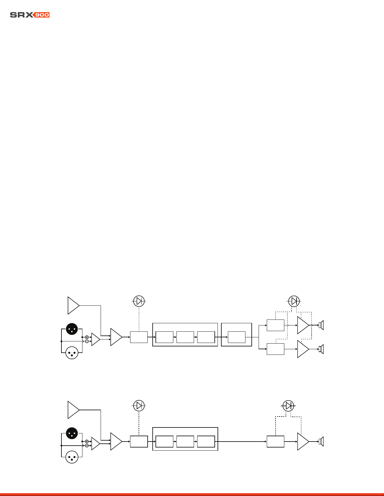
7 - DSP OVERVIEW
A full suite of user-configurable DSP driven by the SRX900 Series’ powerful onboard 400 MHz SHARC DSP includes 24 parametric EQs,
up to two seconds of delay, signal generators, monitoring, and device presets. Additionally, the system features 48 kHz 24-bit process-
ing, LevelMax limiting, and is compatible with JBL’s Performance Audio catalog of products.
XLR IN
XLR OUT
ADC
MIXER
INPUT
METER
GAIN
USER
DELAY
USER
EQ
TDC/
ASC
USER DSP
USER
SIGNAL
GEN
ARRAY TOOLS
SPEAKER
DSP - HF
AMP
SPEAKER
DSP - LF
AMP
LIMIT / FAULT
LED
SIGNAL
LED
MIXER
INPUT
METER
GAIN
USER
DELAY
USER
EQ
USER DSP
USER
SIGNAL
GEN
SPEAKER
DSP - SUB
AMP
XLR IN
XLR OUT
ADC
SIGNAL
LED
LIMIT / FAULT
LED
Line Array Products
Subwoofers
User Manual
16
COVER CLOSED
COVER OPEN
8 - AC POWER
SRX900 products feature Neutrik powerCON TRUE1 TOP (True Outdoor Protection) connectors for power connectivity. TRUE1 TOP
connectors are locking 16 A (20 A for USA) mains connectors specifically designed for the demanding needs of the entertainment in-
dustry. These ruggedized sealed connectors feature an IP65 rating and provide protection from degradation caused by UV in outdoor
applications certifed to the UL 50E standard. Additionally, powerCON TRUE1 TOP connectors feature breaking capacity (CBC), meaning
the connectors can be connected or disconnected under active load. In the case of SRX900 Series products, the powerCON connectors
also serve as the mains ON/OFF switch and no additional/secondary power switch is necessary.
8.2 POWER CONNECTORS
SRX900 Series products include two powerCON TRUE1 TOP connectors, one for AC input and one for AC output/loop through. The
loop through connector allows multiple products to be powered from a single power source. Rubber sealing covers are used to maintain
proper water ingress protection when a connector is not in use.
TIP: One input and one output powerCON TRUE1 TOP connector are included with all SRX900 products. Additional con-
nectors can be purchased from authorized Neutrik resellers.
8.1 AC VOLTAGE REQUIREMENTS
The SRX900 Series amplifier module includes a universal power supply with Power Factor Correction (PFC), which can be used on any
line voltage from 90 V to 250 V depending on the region, the type of wiring, and the power distribution panels available. When the line
voltage goes above or below the set voltage limits, a protection circuit engages to protect the amplifier from damage. In this case, power
to the loudspeaker is interrupted and the power LED at the back of the speaker flashes green to notify the user of improper incoming
power.
The maximum number of loudspeakers that can be looped from the AC output connector is determined by the voltage of the power
source, the type of the looped loudspeakers (subwoofers vs full-range, etc.), and the circuit breaker rating. In general, the higher the line
voltage, the lower the current consumption and the larger the number of speakers that can be used on a single line is. Using too many
speakers looped together will not damage the speakers, but it will trip the mains breaker and interrupt audio once the breaker rating
has been reached.
TIP: For detailed single cabinet current draw specifications refer to Section 17 - Specifications. Current draw and inrush
values for a variety of input voltages are available.
User Manual
17
CAUTION: The number of speakers connected to the same power line should take into consideration the total in-
rush requirements of the speakers and the inrush capabilities of the circuit breaker. Check inrush requirements in
Chapter 17 - Specifications.
CAUTION: The numbers provided in the table above serve as a starting point and do not guarantee uninterrupted
operation. Always make sure sufficient power is available to maintain operation at full output.
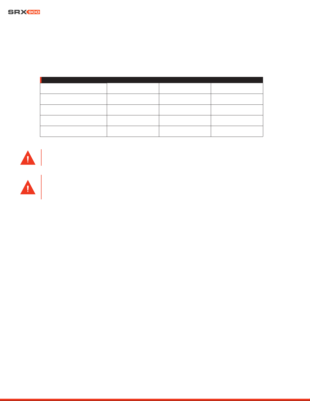
8.3 CURRENT DRAW
The table below serves as a general guideline on the number of SRX900 Series products that can be connected together to a single
power line. As previously discussed, the exact current draw of a speaker can by influenced by a number of factors, including the input
voltage, music type, and cable length. The numbers below serve as a starting point and do not guarantee uninterrupted operation.
NUMBER OF SPEAKERS PER LINE
120 V (15 A) 208 V (15 A) 240 V (16 A)
SRX906LA
(6) (10) (12)
SRX910LA:
(4) (7) (8)
SRX918S
(2) (3) (4)
SRX928S
(1) (3) (3)
8.4 POWER STATES
SRX900 Series speakers can be set to one of two power modes. See Section 15 - LCD for information on how to change between
power modes via the rear LCD.
• Always ON: This is the default power mode. In this case, the speaker will remain always ON and consuming the idle power
listed in Chapter 17 - Specifications.
• Auto Standby: The amplifier can be set to automatically conserve power after the audio drops below a specified level for a
specified amount of time. When activated, auto standby reduces the idle current draw and is recommended for situations where
loudspeakers are always connected to power but not always used. Amplifiers switch ON instantaneously once signal is applied.
This feature can be switched ON/OFF via the LCD or configured via JBL Performance software. JBL Performance allows chang-
ing power parameters, reducing the time needed to setup this feature.
8.5 POWER LED
The power LED displays the current power status as stated below:
• OFF: No power is available.
• Solid GREEN: Power is connected and the speaker is active with no errors.
• Fast flashing GREEN: Power is available but the input voltage is below or above the safe operating range for the amplifier. The
LED will continue to flash until power falls within range. In this state, the LCD, DSP, and amplifier are all OFF
• Slow, GREEN fade-in/fade-out: Power is available without errors. The speaker is in Standby mode. In this case, the LCD dis-
play is OFF.
User Manual
18
9 - AUDIO CONNECTIVITY
SRX900 products are equipped with a balanced line level analog input for interfacing with external audio equipment such as mixing
consoles. The balanced line input can accept signals of up to +21 dBu and has an input impedance of 100 kOhm. The male XLR output
connector allows multiple loudspeakers to be connected together from a single output. The output connector is wired directly to the
input and continues to function under a power loss condition.
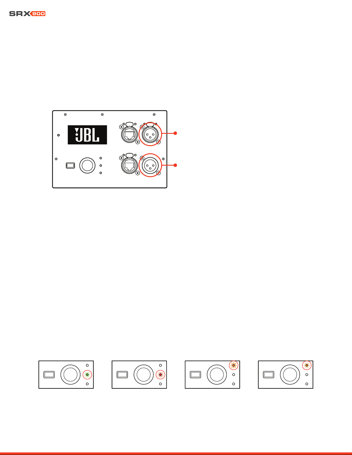
9.1 REAR PANEL AUDIO LEDS
Two LEDs are available on the rear panel to provide visual feedback on system drive. The Signal LED turns green when signal level
higher than -60 dBu is applied at the input, and red when the input signal is clipping the input. The Limit LED turns orange when limiting
is engaged on one or both amplifier channels (LF/HF) to protect the transducers and or amplifiers. This LED is linked to the DSP-based
LevelMAX
TM
limiter and can be activated by the Peak, RMS, or thermal limiter. Limiting is not uncommon and will not damage the trans-
ducers or the amplifier. When the Limit light is solid orange, it means that the system is being driven beyond its capacity and action
should be taken to reduce the input level.
XLR Pin Configuration:
• Pin 1: Ground
• Pin 2: Signal (+)
• Pin 3: Signal (-)
When daisy chaining multiple SRX900 devices together, it is necessary to maintain a 10x relationship between the destination and
source impedances. For example, the mixing console has an output impedance of 100 Ohms, the combined total input impedance of
all SRX900 cabinets would need to be no less than 11,000 Ohms (1 kOhm). Since the input impedance of the amplifier module is 100
kOhms, a maximum of 100 devices would be allowed on an XLR daisy chain in this example.
SIGNAL LED GREEN
SIGNAL LED RED (CLIP) LIMIT LED BLINKING LIMIT LED SOLID
XLR Input
XLR Output
User Manual
19
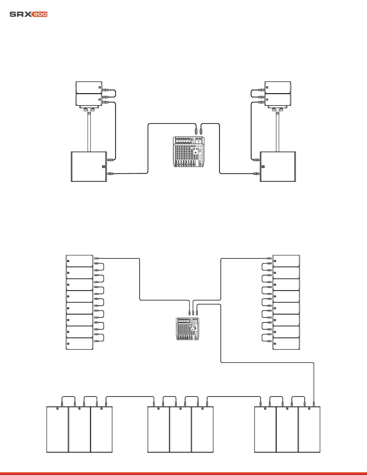
9.2 EXAMPLE: SMALL SYSTEM AUDIO WIRING
In this example, a small SRX900 system is fed from the left and right outputs of a mixer. The signal loops from the subwoofers to the
mains.
9.3 EXAMPLE: LARGE SYSTEM AUDIO WIRING
In this example, a large SRX900 system consisting of SRX910LA suspended mains and SRX928S subwoofers is fed from three separate
signals: left and right sends for the mains and an auxiliary send for the subs. The signal loops though all devices for each feed.

User Manual
20
10- NETWORKING
All SRX900 devices communicate using standard TCP/IP data protocols, and so, like all typical network devices, need a set of unique
addresses to communicate with similar devices on the network, and with the control device running Performance software. In general,
SRX900 devices require the following types of properly configured addresses:
• IP Address
• Subnet Mask
10.1 IP ADDRESSES
IP addresses are used to identify and facilitate network communication between individual devices on a local network. Each SRX900
device within a network requires a unique IP address within a compatible subnet to correctly communicate to the rest of the devices on
the network. IP addresses can be assigned manually by the user, or set automatically by the devices themselves or a DHCP server on
the network. Once IP addresses are set for SRX900 devices and all devices have been verified as being visible and non-conflicting on
the network, it is not necessary for the user to remember the IP address of each device.
IP Address Example: 169.254.12.192
10.2 SUBNET MASK
Every IP address is made up of two unique parts, a host address and a network address. An IP address requires a subnet mask to in-
dicate which part of the address is the host address and which part the network address. It is important for all SRX900 devices on the
network to have the same subnet mask to enable them to communicate without requiring advanced routing configurations.
Subnet Mask Example: 255.255.0.0
10.3 NETWORK CONFIGURATION FOR SRX900 DEVICES
SRX900 devices on a network can be set to either automatically get IP and subnet addresses (DHCP) or be programmed manually by
the user. Modes can be changed from the rear LCD screen or from JBL Performance software utilizing the NetSetter tool.
• DHCP (recommended) - In this mode, IP address and subnet mask information for each device are automatically assigned by a
DHCP server. If no DHCP server is present, the devices will rely on the APIPA (Automatic Private IP Addressing) standard to self-ne-
gotiate IP address and subnet mask information. In most configurations where SRX900 devices are not connected to a strictly
managed or mixed use network, DHCP configuration is the fastest and easiest way to configure all devices and get a system online.
• Static IP - In this mode, the user is responsible for configuring the IP address and subnet mask of every SRX900 device, as well
as the control device on the network. Each device must be assigned the same subnet mask and a unique IP address within the
subnet mask’s range. IP address and subnet mask values can be entered from the rear LCD or from the NetSetter tool within JBL
Performance control software.
TIP: For more information on setting the IP address mode from the rear LCD, see Section 15 - LCD. For more information
on setting the IP address mode from JBL Performance software, see the Performance User Guide available at www.jblpro.
com.
User Manual
21
10.4 ETHERNET PORTS
SRX900 Series amplifier modules are equipped with two fully switched network ports. These ports are used for all data communication
between the amplifier module and the control device running JBL Performance control software. Because these two ports are fully
switched, devices can be daisy chained together to simplify cabling. The standard RJ45 ethernet jack is encapsulated in a Neutrik eth-
erCON® receptacle and can be used with standard RJ45 connectors or etherCON-style connectors for a rugged connection.
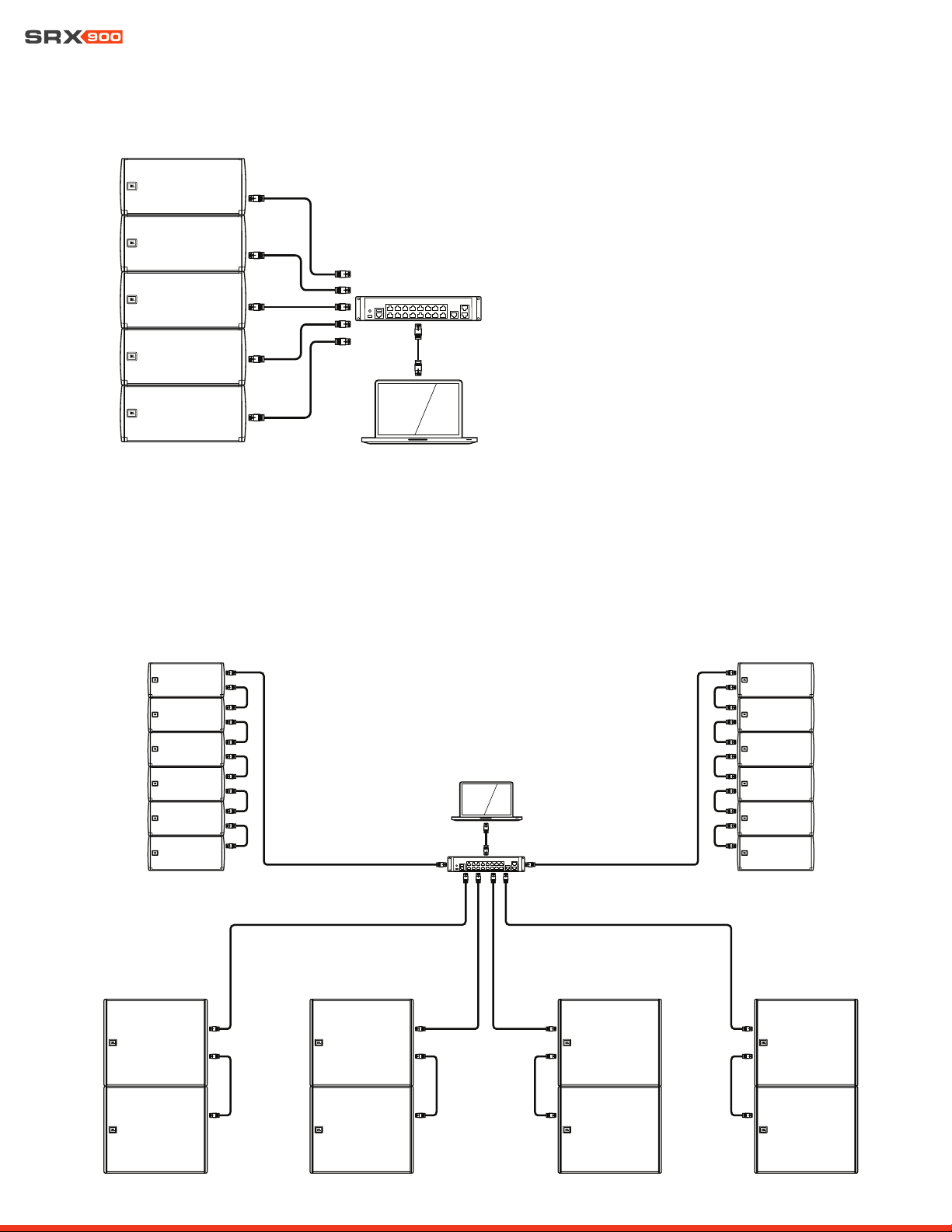
10.5 NETWORK TOPOLOGIES
Three unique network topologies exist for connecting SRX900 Series systems: Daisy Chain, Star, and a Hybrid Daisy Chain/Star. Each
topology is pictured below with a diagram depicting how the system should be wired. Every SRX900 system setup is unique, therefore
no single network setup is universally correct. However, there are pros and cons of each setup that are listed with its wiring diagram.
DATA LED LINK LED
Daisy Chain Network Topology
Pros
• Simple and easy
• Ideal for smaller systems
• Minimal wiring requirements
• Requires no additional network switches.
Cons
• Not recommended for large systems
• Possibility of single point of failure
User Manual
22
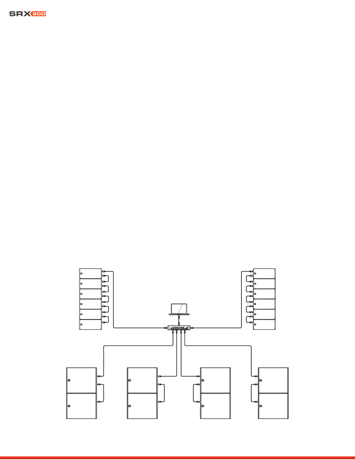
Star Network Topology
Hybrid Daisy Chain and Star Network Topology
Combines the best of both topologies into a production-friendly design that is easy to deploy, easy to cable, minimizes switch hops, and
provides a degree of reliability against power failure.
Pros
• Fast and reliable
• Ideal for large installation where IT is involved
• No single point of failure
• Minimizes device-to-device switch hops
Cons
• Complex and expensive wiring
• Requires external Ethernet equipment
• Not recommended for portable applications
User Manual
23
11 - HCONTROL
SRX900 Series speakers utilize the Harman HControl communication protocol to send messages between devices and applications
such as JBL Performance. HControl is standard TCP/IP traffic and can use off-the-shelf network switches and Wi-Fi access points.
HControl can co-exist with other standard network traffic such as HiQNet, Dante, AES 67, and internet traffic on a shared network.
HControl is an Open Systems Interconnect (OSI) Layer 7 (appllication layer) protocol, registered with the Internet Assigned Numbers
Authority (IANA) as operating over Transmission Control Protocol (TCP) and Uniform Datagram Protocol (UDP) on port 4197.
11.1 HCONTROL ID
HControl IDs (HCID) are designed to provide users with an easy way to match real devices and virtual devices, regardless of network
address or configuration. HCIDs are used to give each device a numeric identifier up to six digits long. Each hardware device has a
fixed HCID set at the factory that the user can modify, either on the device LCD (See Section 15 - LCD for more information) or in JBL
Performance, using the integrated NetSetter tool. The HCID can also be locked from the LCD menu to restrict changes from software.
11.2 HCID USE CASES
JBL Performance software offers a visually intuitive layout of devices in software that mimics the real-world design of the system. Match-
ing the actual hardware to the correct virtual device is the first step in getting the system online. If hardware HCIDs are known, a user can
pre-program the ID in the corresponding virtual location in the software. When the network is up, simply click “Auto Match” in Connect
mode, and the software will automatically match the hardware to the virtual devices. When setting HCID addresses on the hardware, it
is best to choose logical blocks of numbers that are easy to recognize.
11.3 EXAMPLE SYSTEM HCID ADDRESSING
The following example illustrates a recommended approach to addressing devices in a mid-sized system.
101
1000
102
103
104
105
106
201
202
203
204
205
206
301
302
401
402
501
502
601
602

User Manual
24
12 - SPEAKER PRESETS
SRX900 Series speakers have dedicated speaker presets created by JBL engineers to optimize the system for a given use case. These
presets are embedded in the device firmware and may be updated by JBL to further improve performance. They can be recalled and
changed independently of the user DSP and are not editable by the end user.
12.2 SUBWOOFER PRESETS
Low frequency options:
The SRX900 subwoofers support two modes 60 Hz or 80 Hz. When subwoofers are used together with SRX900 line arrays, 80 Hz mode
should always be selected.
Orientation: Forward or Rear
By default, a subwoofer is set as Forward for normal operation. In properly configured subwoofer arrays, a subwoofer’s physical ori-
entation can be changed, which with proper DSP settings, will improve rejection behind the subwoofer array and improve the forward
response. The Rear setting will automatically recall the proper DSP settings to optimize the subwoofer for this configuration, which is
often referred to as a “cardioid subwoofer array”. See Section 14 - Subwoofer Orientation for additional information regarding forward
and rear-facing subwoofers and how to deploy a cardioid subwoofer array.
12.1 LINE ARRAY MODES
SRX900 Series line arrays can be operated in one of three modes depending on the application and the number of speakers within an
array. Operating modes are designed to create a neutral starting point and alter the tonal balance of the speakers to compensate for
low frequency changes caused by array conditions. Select the most appropriate mode for the application at hand via the LCD panel or
software.
FILL: The FL presets (short for FILL) have nominally flat frequency response and are used in situations where individual SRX900 cabinets
are appropriate, such as distributed front fills. This mode is available for both the SRX906LA and SRX910LA.
SMALL ARRAY (SA): The SA preset (short for Small Array) is appropriate in situations where two or three SRX906LA cabinets are placed
on a pole on top of subwoofers. A gentle high frequency shelving response is applied to offset LF/MF array buildup for arrays of two to
three cabinets. This mode is exclusive to the SRX906LA, since the SRX910LA cannot be pole mounted.
ARRAY: This is the standard preset for array use. This preset is available for both models and should be used in all situations where four
or more speakers are used. A high frequency shelving response is applied to offset LF/MF array buildup for nominally focused arrays
(equally spaced impact points over the desired audience coverage area). This mode is compatible with the Array Size Compensation
filter, which can further shape the array buildup for longer arrays.
Low frequency options:
Each line array mode is available in two variants, full-range or 80 Hz. In full-range mode, the acoustical low frequency response of the
system extends as low as possible and should be used when the system is operated without subwoofers. The 80 Hz option is used when
subwoofers are available and when the highest A-weighted sound pressure level (SPL) is required.
CAUTION: When subwoofers are available, the SRX906LA and SRX910LA speakers should always be operated in the
80 Hz mode, which produces the highest A-weighted sound pressure level (SPL) and reduces amplifier resources.
User Manual
25
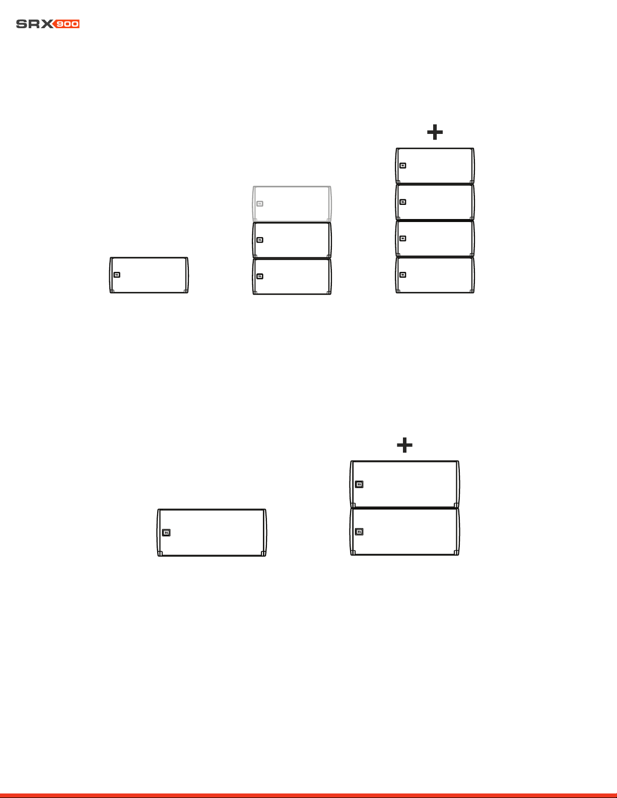
12.4 SRX910LA PRESET EXAMPLES
Both preset modes include Full-Range and 80 Hz HPF options.
12.3 SRX906LA PRESET EXAMPLES
All three preset modes include Full-Range and 80 Hz HPF options.
1 SRX906LA
MODE: FILL
2-3 SRX906LA
MODE: SA
4+ SRX906LA
MODE: ARRAY
1 SRX910LA
MODE: FILL
2+ SRX910LA
MODE: ARRAY
User Manual
26
13 - ARRAY CALIBRATION
SRX900 Series full-range speakers have two dedicated, user-adjustable filters designed to quickly tailor the tonal response of an array.
Each filter serves a specific intended purpose to accelerate the tuning process. Both filters can be applied quickly to all elements in an
array from JBL Performance software, or to array elements one at a time from the LCD on the rear of the cabinets. For more information
on applying Array Calibration filters from the LCD, see Section 15 - LCD, and for information on applying calibration filters from Perfor-
mance control software see the Performance User Guide available at www.jblpro.com
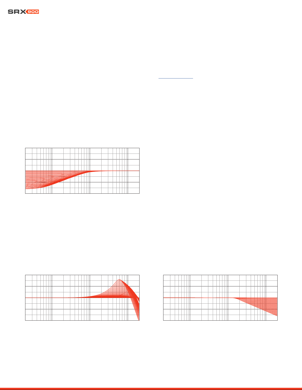
13.1 FILTER 1- ARRAY SIZE COMPENSATION (ASC)
The Array Size Compensation (ASC) filter is designed to work in conjunction with the array presets and it can be used to reduce the en-
ergy created by the coupling effects of arrays in the mid and low frequencies, and bring the array closer to the desired tonal response. LF
adjustments should be applied equally to all cabinets within the array. ASC values can depend on the shape of the array, the acoustics
of a room, or preference. Adjust ASC up or down to achieve the desired tonal result.
13.2 FILTER 2 - THROW DISTANCE COMPENSATION (TDC)
The Throw Distance Compensation (TDC) filter provides a linear phase, EQ and per-cabinet gain adjustment to optimize each array
element for the air absorption effects of distance. TDC is typically applied on a per-cabinet basis, depending on the desired outcome,
with the cabinets throwing further distances typically needing an HF boost, and cabinets throwing short distances needing HF reduction.
Throw Distance Compensation
20 100 1000 10000
20000
Frequency (Hz)
-2
0
-1
0
0
10
20
20 100 100
01
000
02
000
0
Frequency (Hz)
-2
0
-1
0
0
10
20
Proximity Correction
20 100 1000 10000
20000
Frequency (Hz)
-2
0
-1
0
0
10
20
Array Size Compensation
User Manual
27
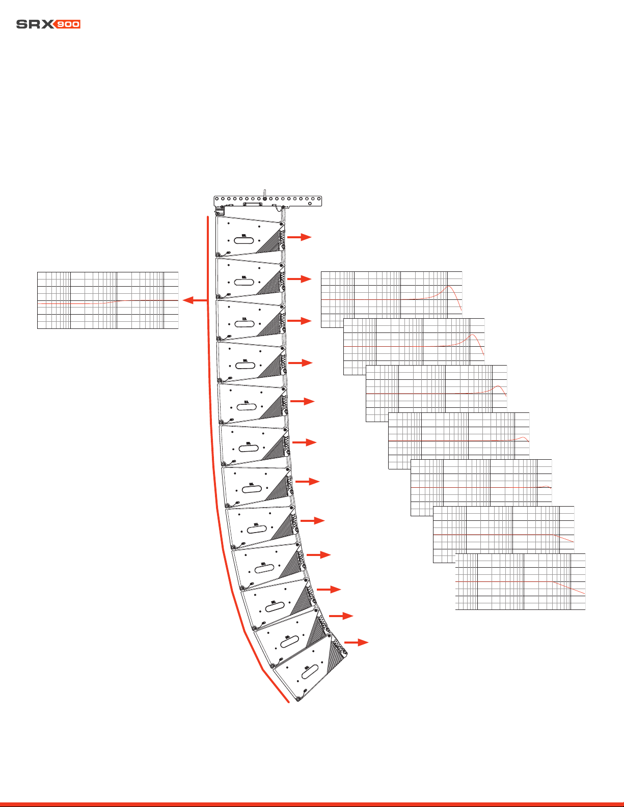
13.3 ARRAY CALIBRATION FILTER EXAMPLE
The example below represents a typical use case for the Array Calibration tool set. The 12-Box SRX906LA array shown below has Array
Size Compensation (ASC) subtracted globally from all elements of the array. The individual speakers within the array have additional
Throw Distance Compensation applied to improve long-throw performance and remove some excess HF that may be present due to the
distance from the array to the front audience members.
ASC Filters Applied Globally TDC Filters Applied to individual cabinets
User Manual
28
14 - SUBWOOFERS
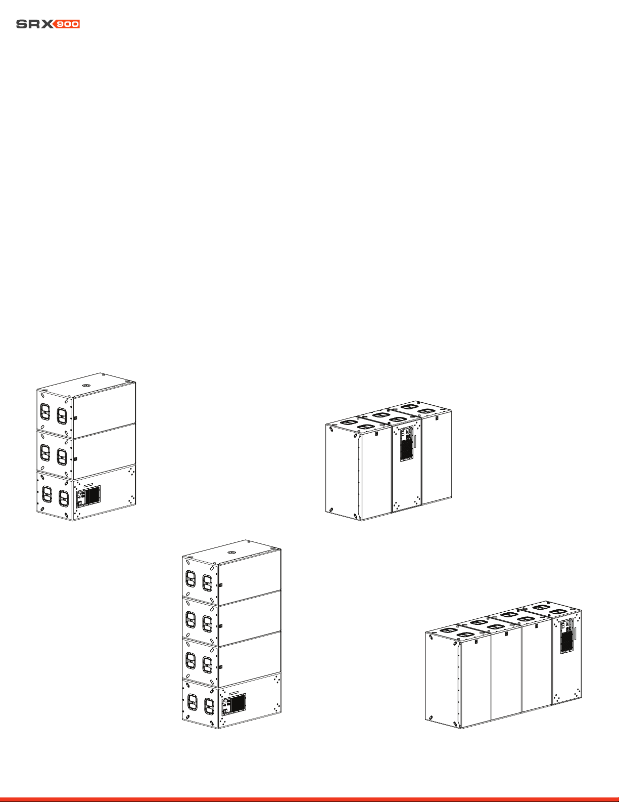
14.2 RECOMMENDED CARDIOID SETUPS
Cardioid configurations are typically differentiated by the ratio of front-facing to rear-facing cabinets, the spacing between stacks, and
the position of rear-facing subwoofers within the stacks. Lower ratios produce higher rejection, higher ratios result in lower rejection. The
SRX9xxS factory presets were engineered to work with blocks having 2:1 and 3:1 ratios, with 2:1 delivering the greatest rear rejection.
Subwoofer arrays designed around a 2:1 ratio can easily generate broadband rejection of 20 to 30 dB. It is NOT advised to go below
2:1 or above 3:1 ratios. If larger arrays are desired, combining cardioid blocks into bigger arrays is possible. Using LAC-3 to predict the
expected coverage of complex arrays is suggested to ensure the intended coverage suits the desired application.
Example 1: 2:1 horizontal stack Example 2: 2:1 on-end
Example 3: 3:1 horizontal stack Example 4: 3:1 on-end
14.1 CARDIOID SUBWOOFERS
In some situations, the omnidirectional nature of subwoofers is desirable, but in others, directional coverage is required. The most
common use case for directional subwoofers involves preventing excessive low frequency energy from reaching the stage. A single sub-
woofer radiates omnidirectionally, but cardioid coverage can be achieved with an array of subwoofers in which the physical orientation
of some cabinets is reversed and the Rear speaker mode selected. The Rear speaker mode sets the DSP parameters to optimize the
system to provide the maximum amount of cancellation possible for most standard configurations without the need for any user DSP
changes.
User Manual
29
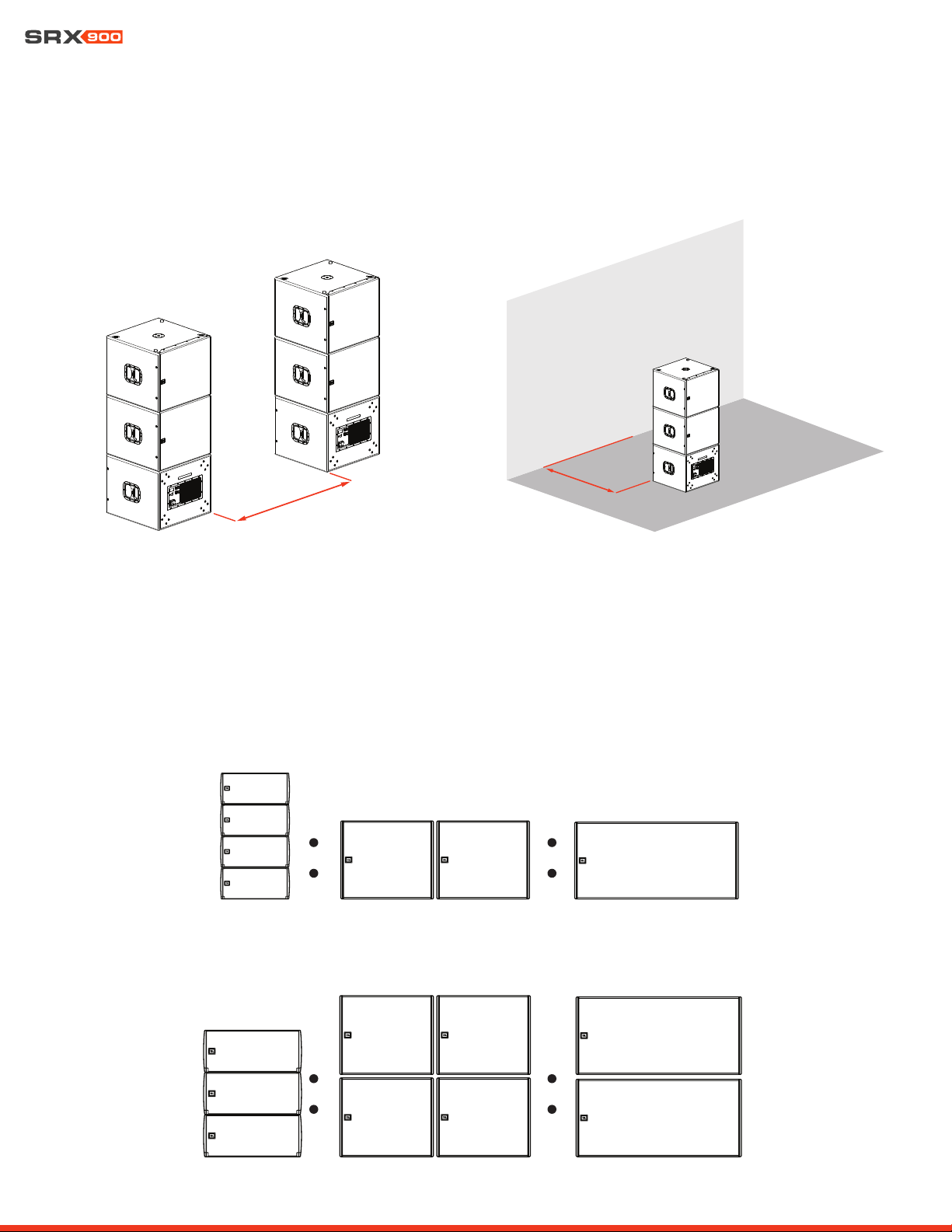
14.3 MINIMUM SPACE BETWEEN CARDIOID STACKS
When creating subwoofer arrays using cardioid blocks of subwoofers, a distance of at least 1 meter (3.2 feet) should be allowed between
stacks and high-mass structures, like a concrete wall or stage, to avoid disrupting rear radiation patterns.
1 m (3.2 ft)
1 m (3.2 ft)
14.4 SUBWOOFER RATIOS
The minimum recommended subwoofer ratios provide sufficient headroom for both the subwoofers and full-range cabinets to reach
MAX SPL (limiters) at the same time, while maintaining a minimum of 10 dB sub to full-range low frequency contour. Other ratios can be
used depending on the desired tonal balance target, maximum SPL, and application.
SRX906LA
SRX910LA
SRX918S SRX928S
SRX918S SRX928S
User Manual
30
MAIN MENU 101
Network
HControl
DSP
15 - LCD
The LCD screen on the rear panel is a powerful tool for accessing speaker parameters, including operating modes (speaker presets)
and network settings. Navigating the menus and changing selected parameters is done with the Encoder. Rotate the Encoder to move
through menus and parameters. When the setting you want to edit is highlighted, press the Encoder to enable editing of the value, rotate
the Encoder to set the desired value, then press the Encoder again to apply the value. Pressing the Encoder acts as an enter button.
The Back button returns to the previous menu. In a confirmation dialog, the Back button acts to cancel the operation.
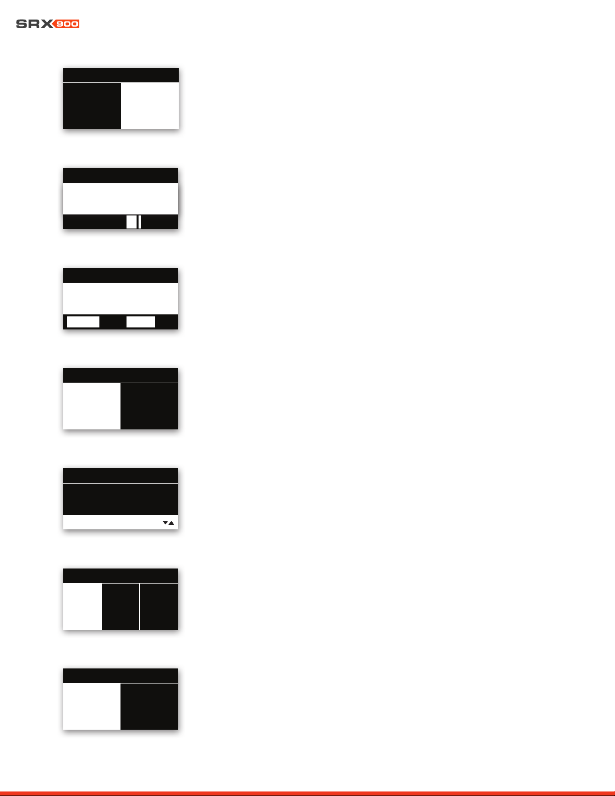
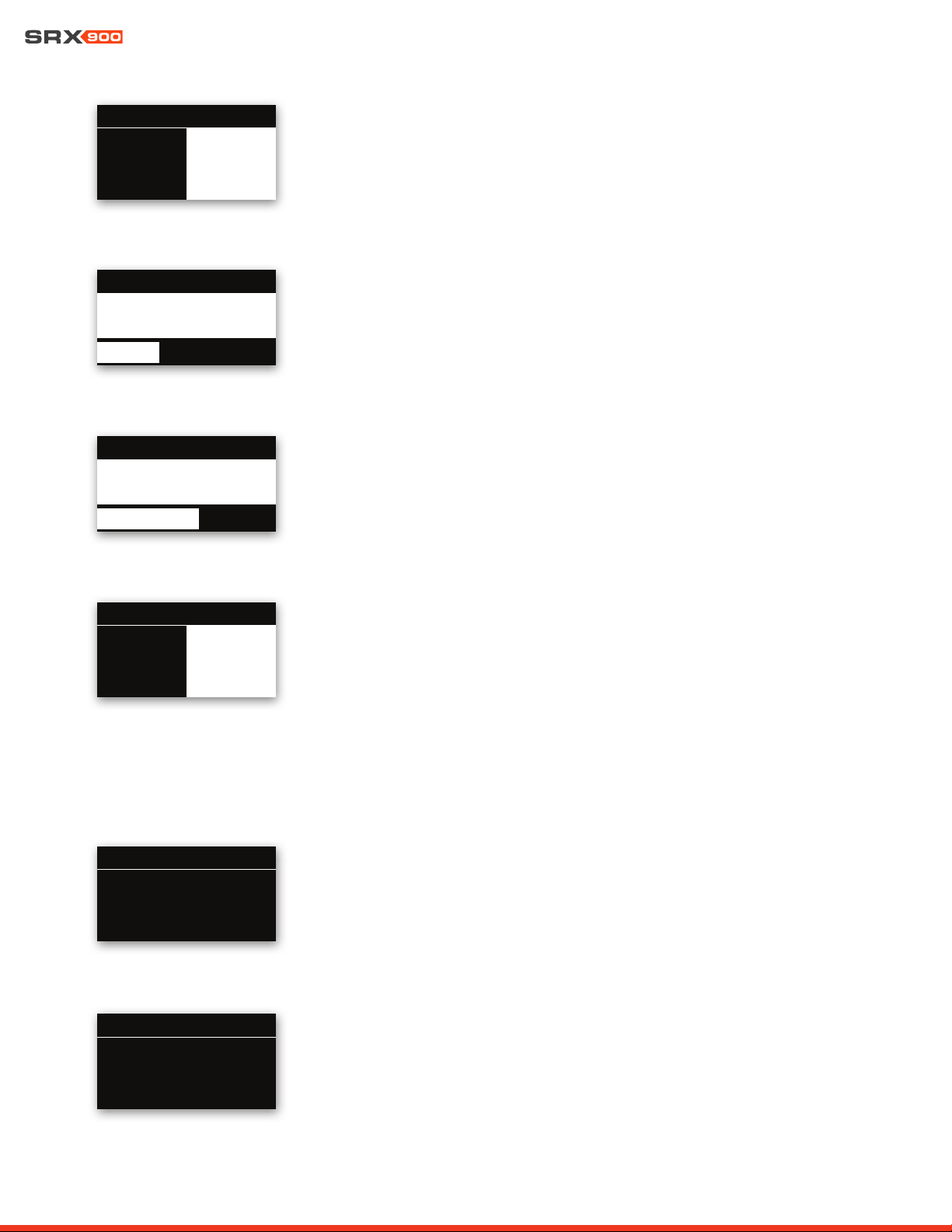
15.1 OVERVIEW SCREENS
LCD Functions Overview:
• DSP Parameters
• Network Settings
• HControl
• Device Settings
• Device Information
• System Reset
LCD
Back Button
Encoder
The Home Screen
This screen is displayed after the amplifier completes its powerup routine, or after one min-
ute of inactivity. It can also be accessed by pressing the Back button from the main menu.
• HControl ID
• Speaker Array/Location Information set from Performance software
Main Menu
Pressing the encoder from the Home screen opens the main menu. The main menu provides
access to all submenus.
• HControl ID
• Current menu position highlighted by the white bar
Array Left : 1
11
0
11
1
2
1
2
3
4
3
4
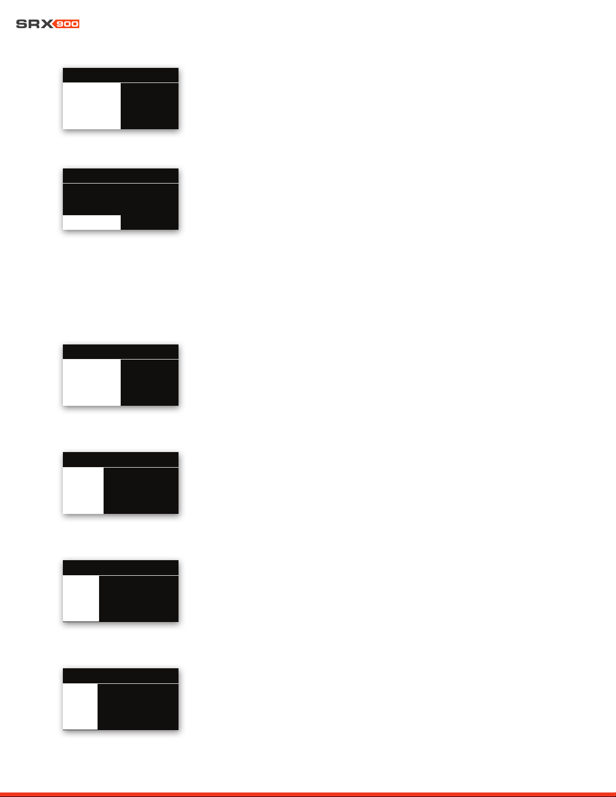
15.2 DSP
DSP Menu
The DSP menu contains high-level DSP parameters for user-adjustable DSP settings.
101
Mute CH1: Unmuted
Gain: 0.00 dB
Mute CH2: Unmuted
DSP
V
User Manual
31
MUTE
To change the Mute setting, use the encoder to select the desired state. Press the encoder
to apply the parameter, and the display will return to the DSP menu. Biamplified systems
will have a mute per bandpass. Pressing the Back button exits the menu without applying
a change.
GAIN
The system input gain can be changed in real time by turning the encoder.
Pressing the Back button exits to the main menu.
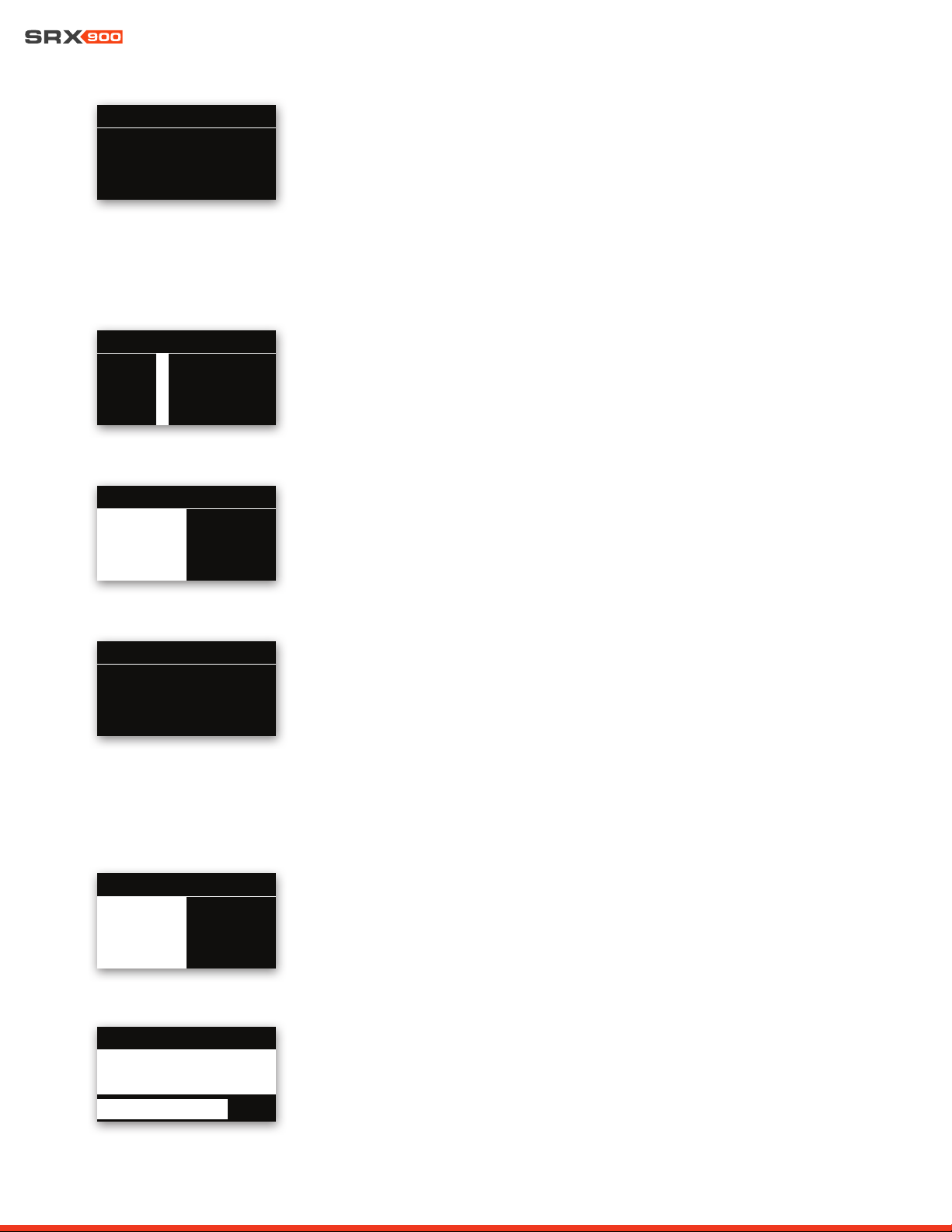
Delay
Delay can be enabled or disabled, and the delay time can be set from 0 ms to 2,000 ms.
User EQ
User EQ is enabled or disabled with this control. User EQ is edited in JBL Performance
software.
101DSP: MUTE CH1
Unmute Mute
V
101DSP: GAIN
-9.50dB
V
101DSP: DELAY
2126.94 ft 648.29 mt
V
1888.87 ms
101
DSP: User EQ
On Off
V
Speaker Mode (Full-range systems only)
For full-range systems, the speaker mode can be set to Array or Fill by turning the encoder,
then pressing on it to apply the selected setting. This change will load a speaker preset in the
speaker DSP, optimized for the indicated use case, and has no effect on User DSP settings.
SRX906LA speakers can also choose the SA preset.
Orientation (Subwoofers only)
For subwoofers, the speaker’s orientation can be set to Forward or Rear. Selecting Rear
loads a speaker preset with factory-optimized DSP settings for rear-facing subwoofers in a
cardioid array.
Array Size Compensation and Throw Distance Compensation
Array Size Compensation (ASC) and Throw Distance Compensation (TDC) can be enabled or
disabled and adjusted in .5 dB increments from -16 dB to +16 dB.
101
ASC Level: 1.0 dB
TDC: Enabled
TDC: Level: 0.0 dB
DSP
V
101
Forward Rear
DSP: ORIENTATION
V
101
Fill
ArraySA
DSP: MODE
V
User Manual
32
Subnet Mask
When the network mode is set to Static, the subnet can be set one octet at a time by using
the encoder to select the desired octet, pressing the knob to enable editing, rotating the
knob to select the desired value, and pressing the knob to store the change. Pressing the
Back button cancels the change.
Gateway
When the network mode is set to Static, the gateway can be set one octet at a time by using
the encoder to select the desired octet, pressing the knob to enable editing, rotating the
knob to select the desired value, and pressing the knob to store the change. Pressing the
Back button cancels the change.
101NETWORK: GATEWAY
V
11
72.
72.
11
6. O. 1
6. O. 1
101NETWORK: SUBNET
V
255.255. 255. 255. 0 255. 255. 0
IP Address
When the network mode is set to Static, the IP can be set one octet at a time by using the
encoder to select the desired octet, pressing the knob to enable editing, rotating the knob
to select the desired value, and pressing the knob to store the change. Pressing the Back
button cancels the change.
101NETWORK: IP
V
11
72.
72.
11
6. O. 76
6. O. 76
15.3 NETWORK
Mode
Press the Encoder to set the Network Mode to DHCP or Static.
101NETWORK: MODE
DHCP Static
V
LF Mode
LF Mode sets the crossover frequency used in the factory presets.
• For full-range systems, the setting options are Full-Range (FR) and 80 Hz
• For subwoofers, the setting options are 60 Hz and 80 Hz.
Reset All DSP
The User DSP section can be returned to factory default values by entering this screen, se-
lecting the OK button with the encoder, and pressing it. On the confirmation screen, select
Confirm, then press the knob a second time to reset the DSP parameters. This operation
cannot be undone and will disconnect the device from connected software. Pressing the
Back button at any time exits to the menu without making a change.
101
60Hz 80 Hz
DSP: LF MODE
V
RESET 101
RESET ALL USER DSP TO DEFAULTS?
THIS CAN NOT BE UNDONE.
NO OK
V
User Manual
33
15.5 SETTINGS
Auto Standby
The amplifier can be set to automatically conserve power when the audio drops below a
specified level for a specified amount of time. The Auto Standby feature can be enabled or
disabled by using the encoder to select On or Off, then pressing the knob to commit the
change. The threshold level can be set using JBL Performance in the Device Control Panel.
HControl Label
This read-only screen displays the HControl label set in the Performance software’s NetSet-
ter window as the identifier of the device.
101
SRX906LA-400082
HCONTROL: LABEL
V
MAC Address
This displays the device’s MAC address. This address is unique to each product and set at
the JBL factory at the time of manufacturing. This address is not user adjustable.
15.4 HCONTROL
HControl ID (HCID)
If the HControl Lock is set to Unlocked, The HControl ID can be set one digit at a time by
using the encoder to select the desired digit. To change the number, press the knob, rotate
the knob to select the desired value, and press the knob to store the change. Pressing the
Back button cancels the change to the digit.
Lock ID
The HControl ID lock disables the ability to change the HControl ID. Select the Lock or Un-
lock setting and press the encoder to confirm the setting. Pressing the Back button exits
without making a change.
101
00:0A:40:30:00:83
NETWORK: MAC
V
101HCONTROL: ID
300082
V
101HCONTROL: LOCK
Unlock Lock
V
Display Brightness
The display brightness can be changed in real time by turning the encoder. Pressing the
Back button exits to the main menu.
101SETTINGS: A-STANDBY
On Off
V
101SETTINGS: LCD BRIGHT
8
V
User Manual
34
Display Auto-Dim
The display can be set to automatically turn off when unused for a specified amount of time.
This feature can be enabled or disabled on the LCD by turning the encoder to select the
desired setting and then pressing it to apply the setting. The threshold time for auto-dim-
ming can be set using JBL Performance in the Device Control Panel or by setting Display
Auto-Dim Time on the LCD.
Display Auto-Dim Time
If Display Auto-Dim is enabled, this sets the amount of time between the last press of a knob
or button on the LCD and when the display turns off. The Auto-Dim Time can be changed in
real time by turning the encoder. Pressing the Back button exits to the main menu.
Ambient Temperature
The Ambient Temperature setting adjusts the equation used to calculate the amount of time
applied when delay is entered as distance to account for the impact of temperature on the
speed of sound, and can be changed in real time by turning the encoder. Pressing the Back
button exits to the main menu.
Locate
The Locate feature flashes the LEDs on the amplifier module and is bidirectionally used, ei-
ther to identify hardware from software, or to identify an associated virtual device in software
from the physical cabinet. This feature can be set from the LCD or from software. Restarting
the device automatically sets this parameter to OFF. The feature can be enabled or disabled
by using the encoder to select On or Off, and then pressing on it to apply the value.
15.6 INFO
Speaker Model
This screen displays the speaker model.
101
SRX906LA
INFO:SPEAKER MODEL
V
Amplifier Version
This screen displays the hardware revision of the amplifier module.
101INFO MENU
F
V
101SETTINGS: LCD A-DIM
Disable Enable
V
101SETTINGS: A-DIMETIME
10 min
V
101SETTINGS: AMB TEMP
20.00 c
V
101SETTINGS: LOCATE
On Off
V

User Manual
35
Firmware Version
This screen displays the loaded firmware version.
15.7 SYSTEM RESET
System Reset
This feature resets all user settings and DSP back to factory defaults. It erases all parameter
settings, network information, stored presets, and all other user-adjustable settings. This ac-
tion cannot be undone. Selecting the OK button with the Encoder and pressing it will bring
the confirmation screen. Selecting Confirm on the confirmation screen and pressing on the
knob a second time resets the device back to defaults. Pressing the Back button exits to the
menu without making a change.
101INFO MENU
1.5.10.59
V
SYSTEM RESET 101
RESET ALL USER PARAMETERS
AND SETTINGS TO DEFAULTS?
NO OK
V
User Manual
36
101
Network
DSP
HControl
MAIN MENU
101
Network
DSP
HControl
MAIN MENU
MAIN MENU 101
Network
HControl
DSP
• Mute: Enable
• Gain: Level
• Delay: Enable
• Delay Time: ms
• User EQ: Enable
• ASC: Enable
• ASC: Level
• TDC: Enable
• TDC: Level
• Speaker Mode/Orientation
• LF Mode
• Reset User DSP
• Mode
• IP Address
• Subnet Mask
• Gateway
• MAC Address
• HControl ID (HCID)
• Lock HControl ID
• HControl Label
• Speaker Model
• Amp Version
• Firmware Version
• Auto Standby
• Display Brightness
• Display Auto-Dim
• Auto-Dim Time
• Ambient Temperature
• Locate
• Confirm Reset
15.8 MENU OVERVIEW
The graphic below represents all options and settings available from the rear LCD screen on the SRX900 Series products.
MAIN MENU 101
Settings
Factory Reset
Info
MAIN MENU 101
Settings
Factory Reset
Info
MAIN MENU 101
Settings
Factory Reset
Info
User Manual
37
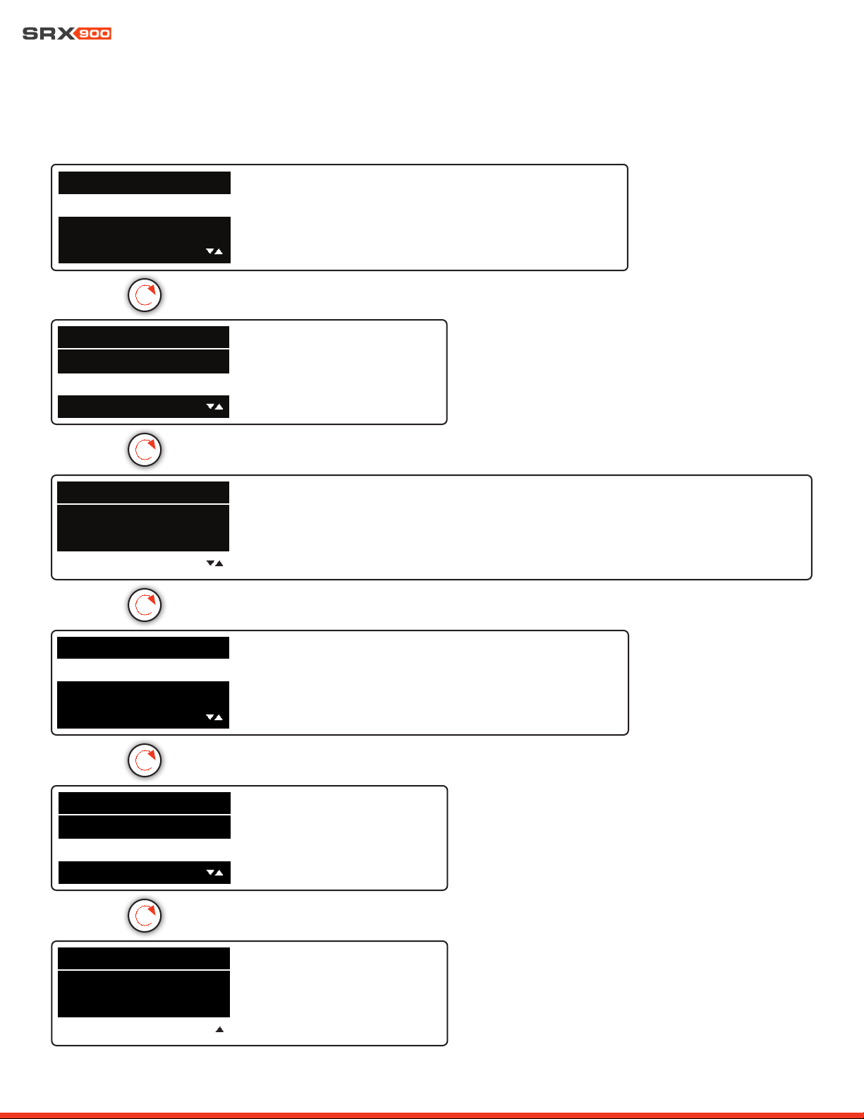
15.9 REVERT FIRMWARE
SRX9xx products contain two versions of firmware within the devices memory: the current firmware the device uses to operate, and
the previous version of firmware. In the event it is necessary to revert an SRX9xx product to the prevous version of firmware, follow the
steps below.
STEPS:
• Disconnect power to the product
• Hold down the Back and Encoder buttons simultaneously
• Power on the product
• Continue to hold down both buttons until LCD displays “Reverting Firmware”
• Release the buttons and allow device to boot up
1
2
3
4
REVERTING FIRMWARE...
RELEASE BUTTONS
Back Button
Encoder
5
User Manual
38
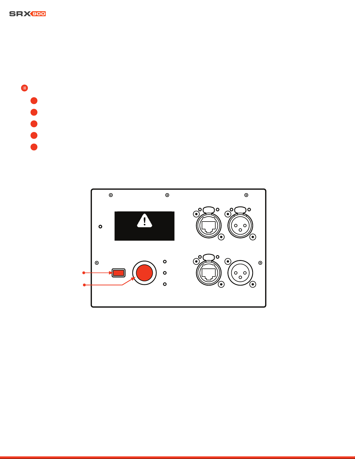
16 - SRX900 RC RAIN COVER
The SRX900 RC Rain Cover is a rugged weather-resistant protective cover that installs easily over top any SRX900 Series amplifier mod-
ule to protect the amplifier LCD screen and connections from moisture. The Rain Cover has Velcro strips sewn to its edges to allow the
user to close the cover over top of the connections once system setup is complete. The cover is depicted on an SRX918S below, but is
a universal part that can fit on any of the SRX900 Series products.
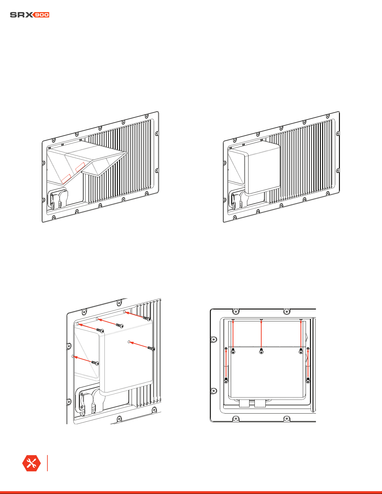
16.1 INSTALLING THE SRX900 RC RAIN COVER
To Install the Rain Cover, line the holes in the Rain Cover frame up to the threaded mounting points on the amplifier module and install
the five screws included with the Rain Cover kit.
TOOLS REQUIRED: A Torx T15 driver is required to install the Rain Cover.
RAIN COVER OPEN
RAIN COVER CLOSED

User Manual
39
17 - PRODUCT SPECIFICATIONS
SRX906LA
AMPLIFIER
Type :
Class-D
Number of Channels :
(2)
Continuous Power
2
:
600 Watts LF: 400 Watts | HF: 200 Watts
Peak Power
3
:
880 Watts LF: 580 Watts | HF: 300 Watts
Cooling Type :
Convection, external aluminum heat sink, internal on-demand fan
ACOUSTICAL
Frequency Range
(-10 dB) :
(-3 dB) :
63 Hz-17 kHz (array preset)
70 Hz-15 kHz (array preset)
Coverage Pattern (-6 dB)
Horizontal :
Vertical :
120 degrees nominal (500 Hz-16 kHz)
Varies with array size and configuration
Maximum Peak Output
1
:
134 dB
System Type :
Line Array, two-way active
TRANSDUCERS
Low Frequency :
(2) JBL 2186G, 6.5 in diameter, dual 2.0 in diameter voice coil, neodymium Differential Drive
®
High Frequency :
(1) JBL 2432H-3, 1.5 in exit neodymium compression driver with 3 in voice coil
AUDIO INPUT
Input Type :
Balanced line level
Connectors :
(2) Neutrik XLR (IN/OUT)
Nominal Input Sensitivity :
+6 dBu (system starts limiting with broadband noise and music)
Maximum Input Level :
21 dBu
Input Impedance :
100 kΩ
DSP
Sample Rate :
48 kHz
Bit Depth :
24 bit
USER INTERFACE
Type :
LCD screen, encoder, Back button, (4) LED Indicators (3 single, 1 bi-color)
Footnotes:
1: Peak, unweighted SPL, measured under full-space conditions at 1 meter using broadband pink noise with a 12 dB crest factor and specified preset.
2: Bench power: ≥1 sec, 1 kHz, 120 VAC, no DSP, all channels driven.
3: Burst power: ≥20 ms, 1 kHz, 120 VAC, no DSP, all channels driven.
User Manual
40
PHYSICAL
Enclosure :
Polypropylene, four integral recessed handholds
IP Rating
7
:
IP54
Suspension :
Three-point captive suspension plates, quick release pins, steel with anti-corrosion coating
Inter-enclosure Angle (deg) :
0.5, 1, 2, 3, 4, 5, 6, 7, 8, 9, 10, 11, 12
Grille :
Powder coated 1.5 mm (16-gauge) hex perforated steel with acoustically transparent black cloth backing
Dimensions (H x W x D) :
243 mm x 507 mm x 420 mm
9.5 in x 19.9 in x 16.5 in
Net Weight :
Shipping Weight :
16.8 kg (37 lbs)
19.4 kg (43 lbs)
NETWORKING
Type :
TCP/IP
Protocol :
Harman HControl
Speed :
Dual 100 Mbps ports
Connectors :
(2) Neutrik etherCON
®
AC POWER
Voltage Range
Nominal :
Limits :
100-240 VAC, 50/60 Hz
80-260 VAC, 50/60 Hz
Connectors :
Dual (IN/OUT) Neutrik powerCON TRUE1 TOP
®
CURRENT DRAW
120 V 208 V 240 V
Standby :
0.2 A 0.1 A 0.1 A
Idle :
0.3 A 0.2 A 0.2 A
Continuous
4
:
1.3 A 0.8 A 0.7 A
Maximum Instantaneous Peak
5
:
7.0 A 5.4 A 4.7 A
Peak Inrush
6
:
2.2 A 3.6 A 4.3 A
ORDERING INFORMATION
SKU :
JBL-P3230MX | SRX906LA for Global
JBL-P3246MXCN | SRX906LA for China
Included :
(1) SRX906LA | (1) Neutrik NAC3FX-W-TOP | (1) Neutrik NAC3MX-W-TOP
Footnotes:
4: System test using IEC shaped pink noise with 9 dB crest factor. System at maximum output without clipping or limiting. Ambient temperature: 20° C. Duration: 5 sec.
5: Two-tone, all channels driven, IMD test at maximum power and a duration of 200 ms.
6: Measured RMS inrush current for a 50 ms window.
7: With use of SRX900 RC1 rain cover (JBL-P3239MX ) and front face at -10 degrees or greater down angle. Suspension components fully weather rated for indoor or covered outdoor conditions where humidity is nominally
under 50% and not local to bodies of corrosive materials.
User Manual
41
SRX910LA
ACOUSTICAL
Frequency Range
(-10 dB) :
(-3 dB) :
53 Hz-19 kHz (array preset)
60 Hz-18 kHz (array preset)
Coverage Pattern (-6 dB)
Horizontal:
Vertical:
105 degrees nominal (400 Hz-16 kHz)
Varies with array size and configuration
Maximum Peak Output
1
:
135 dB
System Type :
Line Array, two-way active
TRANSDUCERS
Low Frequency :
(2) JBL 261G-1, 10 in diameter, dual 2.0 in diameter voice coil, neodymium Differential Drive®
High Frequency :
(1) JBL 2432H-3, 1.5 in exit neodymium compression driver with 3 in voice coil
AUDIO INPUT
Input Type :
Balanced line level
Connectors :
(2) Neutrik XLR (IN/OUT)
Nominal Input Sensitivity :
+6 dBu (system starts limiting with broadband noise and music)
Maximum Input Level :
21 dBu
Input Impedance :
100 kΩ
DSP
Sample Rate
48 kHz
Bit Depth :
24 bit
USER INTERFACE
Type :
LCD screen, encoder, Back button, (4) LED Indicators (3 single, 1 bi-color)
AMPLIFIER
Type :
Class-D
Number of Channels :
(2)
Continuous Power
2
:
600 Watts LF: 400 Watts | HF: 200 Watts
Peak Power
3
:
880 Watts LF: 580 Watts | HF: 300 Watts
Cooling Type :
Convection, external aluminum heat sink, internal on-demand fan
Footnotes:
1: Peak, unweighted SPL, measured under full-space conditions at 1 meter using broadband pink noise with a 12 dB crest factor and specified preset
2: Bench power: ≥1 sec, 1 kHz, 120 VAC, no DSP, all channels driven
3: Burst power: ≥20 ms, 1 kHz, 120 VAC, no DSP, all channels driven
User Manual
42
PHYSICAL
Enclosure :
Polypropylene, aluminum baffle, plywood internal bracing, four integral recessed handholds
IP Rating
7
:
IP54
Suspension :
Three-point, captive suspension plates, quick release pins, steel with anti-corrosion coating
Inter-enclosure Angle (deg) :
0.5, 1, 2, 3, 4, 5, 6, 7, 8, 9, 10, 11, 12
Grille :
Powder coated 1.5 mm (16-gauge) hex perforated steel with acoustically transparent black cloth backing
Dimensions (H x W x D) :
305 mm x 716 mm x 519 mm
12.0 in x 28.2 in x 20.5 in
Net Weight :
Shipping Weight :
26.7 kg (59 lbs)
30.3 kg (67 lbs)
NETWORKING
Type :
TCP/IP
Protocol :
Harman HControl
Speed :
Dual 100 Mbps ports
Connectors :
(2) Neutrik etherCON
®
AC POWER
Voltage Range
Nominal :
Limits :
100-240 VAC, 50/60 Hz
80-260 VAC, 50/60 Hz
Connectors :
Dual (IN/OUT) Neutrik powerCON TRUE1 TOP
®
CURRENT DRAW
120 V 208 V 240 V
Idle :
0.3 A 0.2 A 0.2 A
Standby :
0.2 A 0.1 A 0.1 A
Continuous
4
:
1.9 A 1.1 A 1.0 A
Maximum Instantaneous Peak
5
:
7.0 A 6.4 A 6.2 A
Peak Inrush
6
:
2.2 A 3.6 A 4.3 A
ORDERING INFORMATION
SKU :
JBL-P3234MX | SRX910LA for Global
JBL-P3247MXCN | SRX910LA for China
Included :
(1) SRX910LA | (1) Neutrik NAC3FX-W-TOP | (1) Neutrik NAC3MX-W-TOP
Footnotes:
4: System test using IEC shaped pink noise with 9 dB crest factor. System at maximum output without clipping or limiting. Ambient temperature: 20° C. Duration: 5 sec.
5: Two-tone, all channels driven, IMD test at maximum power and a duration of 200 ms.
6: Measured RMS inrush current for a 50 ms window.
7: With use of SRX900 RC1 rain cover (JBL-P3239MX ) and front face at -10 degrees or greater down angle to allow the cabinet to drain water. Suspension components fully weather rated for indoor or covered outdoor
conditions where humidity is nominally under 50% and not local to bodies of corrosive materials.
User Manual
43
SRX918S
ACOUSTICAL
Frequency Range
(-10 dB) :
(-3 dB) :
35 Hz-90 Hz (Preset: 80 Hz)
45 Hz-80 Hz (Preset: 80 Hz)
Coverage Pattern Options
1
:
Omnidirectional or Cardioid
Maximum Peak Output² :
134 dB (Preset: 80 Hz)
System Type :
Active Subwoofer
TRANSDUCERS
Low Frequency :
(1) JBL 2279G-1, 18 in diameter, 4 ohms, dual 3.0 in diameter voice coil, ferrite Differential Drive
®
AUDIO INPUT
Input Type :
Balanced line level
Connectors :
(2) Neutrik XLR (IN/OUT)
Nominal Input Sensitivity :
+6 dBu (system starts limiting with broadband noise and music)
Maximum Input Level :
21 dBu
Input Impedance :
100 kΩ
DSP
Sample Rate
48 kHz
Bit Depth :
24 bit
USER INTERFACE
Type :
LCD screen, encoder, Back button, (4) LED Indicators (3 single, 1 bi-color)
Footnotes:
1: Based on speaker preset selection and cabinet orientation/configuration
2: Peak, unweighted SPL, measured under half-space conditions at 1 meter using broadband pink noise with a 12 dB crest factor and specified preset
3: Bench power: ≥1 sec, 1 kHz, 120 VAC, no DSP, all channels driven
4: Burst power: ≥20 ms, 1 kHz, 120 VAC, no DSP, all channels driven
AMPLIFIER
Type :
Class-D
Number of Channels :
(1)
Continuous Power
3
:
1100 Watts
Peak Power
4
:
2500 Watts
Cooling Type :
Convection, external aluminum heat sink, internal on-demand fan

User Manual
44
Footnotes:
5: System test using IEC shaped pink noise with 9 dB crest factor. System at maximum output without clipping or limiting. Ambient temperature: 20° C. Duration: 5 sec.
6: Two-tone, all channels driven, IMD test at maximum power and a duration of 200 ms.
7: Measured RMS inrush current for a 50 ms window.
8: With use of SRX900 RC1 rain cover (JBL-P3239MX ) and front face at 0 degrees or greater down angle to allow the cabinet to drain water. Components fully weather rated for indoor or covered outdoor conditions where
humidity is nominally under 50% and not local to bodies of corrosive materials.
PHYSICAL
Enclosure :
18 mm plywood, Black DuraFlex
TM
finish, two integral recessed handles
IP Rating
8
:
IP54
Grille :
Powder coated 1.8 mm (14-gauge) hex perforated steel with acoustically transparent black cloth backing
Dimensions (H x W x D) :
575 mm x 684 mm x 683 mm
22.6 in x 26.9 in x 26.9 in
Net Weight :
Shipping Weight :
44.5 kg (98 lbs)
51.8 kg (114 lbs)
AC POWER
Voltage Range
Nominal :
Limits :
100-240 VAC, 50/60 Hz
80-260 VAC, 50/60 Hz
Connectors :
Dual (IN/OUT) Neutrik powerCON TRUE1 TOP
®
CURRENT DRAW
120 V 208 V 240 V
Idle :
0.3 A 0.2 A 0.2 A
Standby :
0.2 A 0.2 A 0.2 A
Continuous
5
:
4.0 A 2.1 A 1.9 A
Maximum Instantaneous Peak
6
:
18.1 A 8.6 A 7.3 A
Peak Inrush
7
:
2.9 A 5.1 A 5.9 A
ORDERING INFORMATION
SKU :
JBL-P3241MX | SRX918S for Global
JBL-P3248MXCN | SRX918S for China
Included :
(1) SRX918S | (1) Neutrik NAC3FX-W-TOP | (1) Neutrik NAC3MX-W-TOP
NETWORKING
Type :
TCP/IP
Protocol :
Harman HControl
Speed :
Dual 100 Mbps ports
Connectors :
(2) Neutrik etherCON
®
User Manual
45
SRX928S
ACOUSTICAL
Frequency Range
(-10 dB) :
(-3 dB) :
31 Hz-100 Hz (Preset: 80 Hz)
39 Hz-80 Hz (Preset: 80 Hz)
Coverage Pattern Options
1
:
Omnidirectional or Cardioid
Maximum Peak Output² :
140 dB (Preset: 80 Hz)
System Type :
Active Subwoofer
TRANSDUCERS
Low Frequency :
(2) JBL 2279H-1, 18 in diameter, 8 ohms, dual 3.0 in diameter voice coil, ferrite Differential Drive
®
AUDIO INPUT
Input Type :
Balanced line level
Connectors :
(2) Neutrik XLR (IN/OUT)
Nominal Input Sensitivity :
+6 dBu (system starts limiting with broadband noise and music)
Maximum Input Level :
21 dBu
Input Impedance :
100 kΩ
DSP
Sample Rate
48 kHz
Bit Depth :
24 bit
USER INTERFACE
Type :
LCD screen, encoder, Back button, (4) LED Indicators (3 single, 1 bi-color)
AMPLIFIER
Type :
Class-D
Number of Channels :
(1)
Continuous Power
3
:
1100 Watts
Peak Power
4
:
2500 Watts
Cooling Type :
Convection, external aluminum heat sink, internal on-demand fan
Footnotes:
1: Based on speaker preset selection and cabinet orientation/configuration.
2: Peak, unweighted SPL, measured under half-space conditions at 1 meter using broadband pink noise with a 12 dB crest factor and specified preset.
3: Bench power: ≥1 sec, 1 kHz, 120 VAC, no DSP, all channels driven.
4: Burst power: ≥20 ms, 1 kHz, 120 VAC, no DSP, all channels driven.
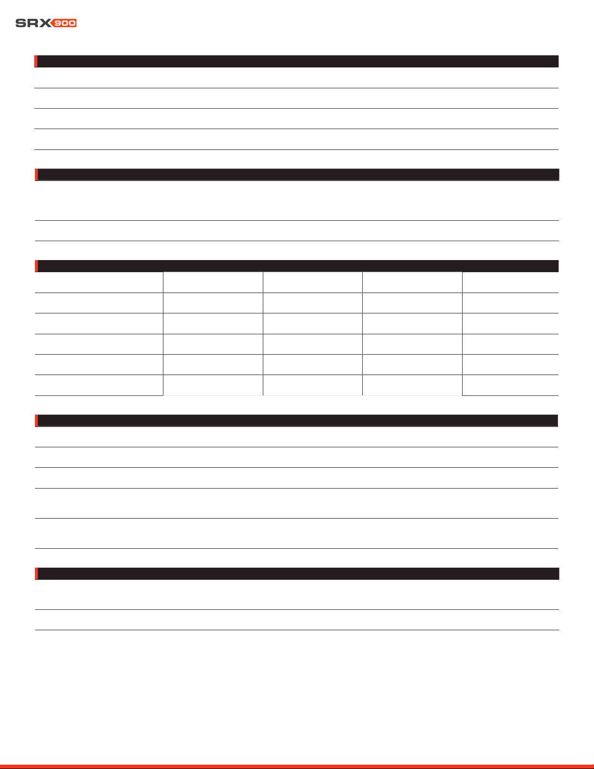
User Manual
46
PHYSICAL
Enclosure :
18 mm plywood, Black DuraFlex
TM
finish, four integral recessed handles
IP Rating
8
:
IP54
Grill :
Powder coated 1.8 mm (14-gauge) hex perforated steel with acoustically transparent black cloth backing
Dimensions (H x W x D) :
565 mm x 1,205 mm x 681 mm
22.2 in x 47.4 in x 26.8 in
Net Weight :
Shipping Weight :
70.3 kg (155 lbs)
81.8 kg (180 lbs)
AC POWER
Voltage Range
Nominal :
Limits :
100-240 VAC, 50/60 Hz
80-260 VAC, 50/60 Hz
Connectors :
Dual (IN/OUT) Neutrik powerCON TRUE1 TOP
®
CURRENT DRAW
120 V 208 V 240 V
Standby :
0.2 A 0.2 A 0.2 A
Idle :
0.3 A 0.2 A 0.2 A
Continuous
5
:
4.8 A 2.4 A 2.1 A
Maximum Instantaneous Peak
6
:
18.2 A 8.6 A 7.3 A
Peak Inrush
7
:
2.9 A 5.1 A 5.9 A
ORDERING INFORMATION
SKU :
JBL-P3243MX | SRX928S for Global
JBL-P3249MXCN | SRX928S for China
Included :
(1) SRX928S | (1) Neutrik NAC3FX-W-TOP | (1) Neutrik NAC3MX-W-TOP
NETWORKING
Type :
TCP/IP
Protocol :
Harman HControl
Speed :
Dual 100 Mbps ports
Connectors :
(2) Neutrik etherCON
®
Footnotes:
5: System test using IEC shaped pink noise with 9 dB crest factor. System at maximum output without clipping or limiting. Ambient temperature: 20° C. Duration: 5 sec.
6: Two-tone, all channels driven, IMD test at maximum power and a duration of 200 ms.
7: Measured RMS inrush current for a 50 ms window.
8: With use of SRX900 RC1 rain cover (JBL-P3239MX ) and front face at 0 degrees or greater down angle to allow the cabinet to drain water. Components fully weather rated for indoor or covered outdoor conditions where
humidity is nominally under 50% and not local to bodies of corrosive materials.

User Manual
47
18 - REGULATORY SPECIFICATIONS
REGULATORY SPECIFICATIONS
Operating Temperature Range :
0-40° C (32-104° F)
Maximum Operating Altitude :
2000 m (6,561 ft.)
Safety Voltage Range :
100-240 VAC, 50/60 Hz
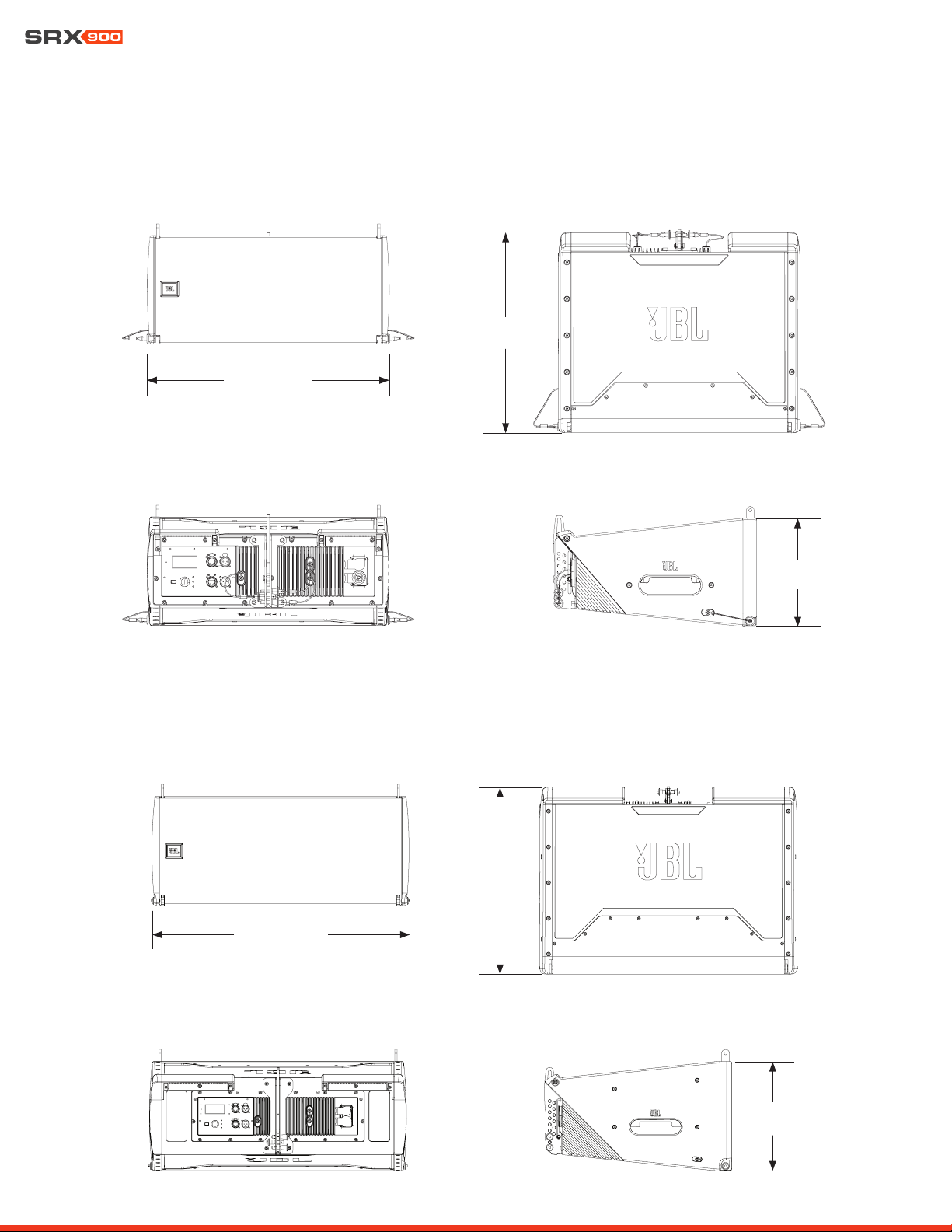
User Manual
48
19 - DIMENSIONS
507 mm (19.9 in)
420 mm
(16.5 in)
227 mm
(8.9 in)
FRONT TOP/BOTTOM
REAR LEFT/RIGHT
716 mm (28.2 in)
472 mm
(18.6 in)
305 mm
(12.0 in)
FRONT TOP/BOTTOM
REAR LEFT/RIGHT
SRX906LA
SRX910LA
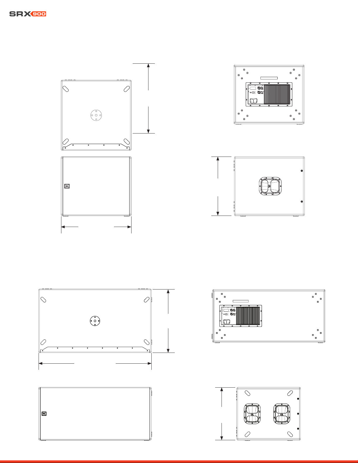
User Manual
49
684 mm (26.9 in)
683 mm
(26.9 in)
575 mm
(22.6 in)
REAR
LEFT/RIGHT
TOP
FRONT
1,205 mm (47.4 in)
681 mm
(26.8 in)
565 mm
(22.2 in)
REAR
LEFT
TOP
FRONT
SRX918S
SRX928S

User Manual
50
20 - CONTACT INFORMATION
Contact the JBL Professional distributor in your area. A complete list of JBL Professional international distributors is provided at our
U.S.A. website: www.jblpro.com
HARMAN Professional EMEA
Westside
London Road
Hemel Hempstead
HP3 9TD
United Kingdom
www.pro.harman.com
www.jblpro.com/support
HARMAN Professional APAC
108 Pasir Panjang Road
#02-08 Golden Agri Plaza
Singapore 118535
+65 6870-5000
www.pro.harman.com
www.jblpro.com/support
HARMAN Professional China
20F, China Merchants Port Plaza, #1
Gongye 3rd Road, Shekou, Nanshan
Dist.
Shenzhen, 518067, China
400 166 7806
www.harman.com/China
HARMAN Professional India
Prestige Technology Park
Jupiter 2A Block, 4th Floor
Marathahalli Ring Road
Bangalore 560103, India
+1 (800) 208-8880
www.harman.com/India
HARMAN Professional Solutions
8500 Balboa Blvd.
Northridge, CA 91329
USA
+1 (844) 776-4899
www.jblpro.com
U.S.A. Technical Support
+1 (800) 852-5776
HProT[email protected]
www.jblpro.com
UNITED STATES OF AMERICA
PROFESSIONAL CONTACTS, OUTSIDE THE U.S.A.:
China In-Country Support
India In-Country Support
www.harman.com/india/india-service-center
HARMAN Professional Brazil
Br386, Km435 92480-000
Nova Santa Rita Rs
Brazil
+55 51 34794000
www.harman.com/Brasil
www.jblaudio.com.br
Brazil In-Country Support