Loading ...
Loading ...
Loading ...
Section 4 - ADJUSTMENT & REPAIR
WARNING
DO NOT attempt any adjustments, maintenance or
service with the engine or blade running. STOP blade.
STOP engine. Set brake. Remove key. Remove spark
plug wire from spark plug and secure wire away from
spark plug. Engine and components can be extremely
hot. Avoid burns by allowing engine and components
sufficient time to cool.
4.3.2. STEERING ADJUSTMENT
Should excessive "Play" be noted in the steering,
adjust as follows:
1. Turn engine "OFF". Remove key
2. From Ieft side of tractor, locate the steering sector
below fuel tank. See Figure 4.19
e-_FUELTANK
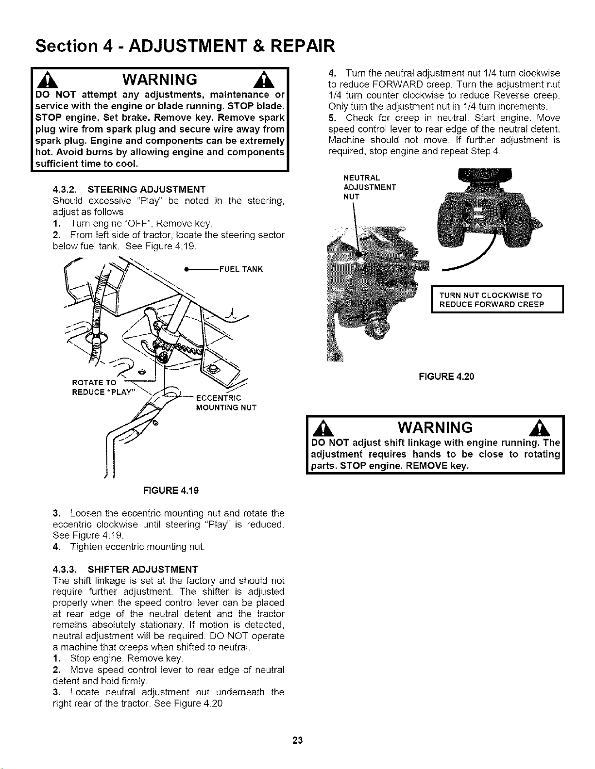
4. Turn the neutral adjustment nut 1/4 turn clockwise
to reduce FORWARD creep. Turn the adjustment nut
1/4 turn counter clockwise to reduce Reverse creep.
Only turn the adjustment nut in 1/4 turn increments.
5. Check for creep in neutral. Start engine. Move
speed control lever to rear edge of the neutral detent.
Machine should not move. If further adjustment is
required, stop engine and repeat Step 4.
NEUTRAL
ADJUSTMENT
NUT
I URN NUT CLOCKWISE TO I
REDUCEFORWARDCREEP
ROTATE TO
FIGURE 4.20
MOUNTING NUT
FIGURE 4,19
3. Loosen the eccentric mounting nut and rotate the
eccentric clockwise until steering "Play" is reduced.
See Figure 4.19.
4. Tighten eccentric mounting nut.
4.3.3. SHIFTER ADJUSTMENT
The shift linkage is set at the factory and shouId not
require further adjustment. The shifter is adjusted
properly when the speed control lever can be placed
at rear edge of the neutral detent and the tractor
remains absolutely stationary. If motion is detected,
neutral adjustment will be required. DO NOT operate
a machine that creeps when shifted to neutral.
1. Stop engine. Remove key.
2, Move speed control lever to rear edge of neutral
detent and hold firmly.
3. Locate neutral adjustment nut underneath the
right rear of the tractor. See Figure 4.20
WARNING I
DO NOT adjust shift linkage with engine running. The I
adjustment requires hands to be close to rotating I
parts. STOP engine. REMOVE key. I
23
Loading ...
Loading ...
Loading ...