Loading ...
Loading ...
Loading ...
Page 27
Indoor Unit
Installation
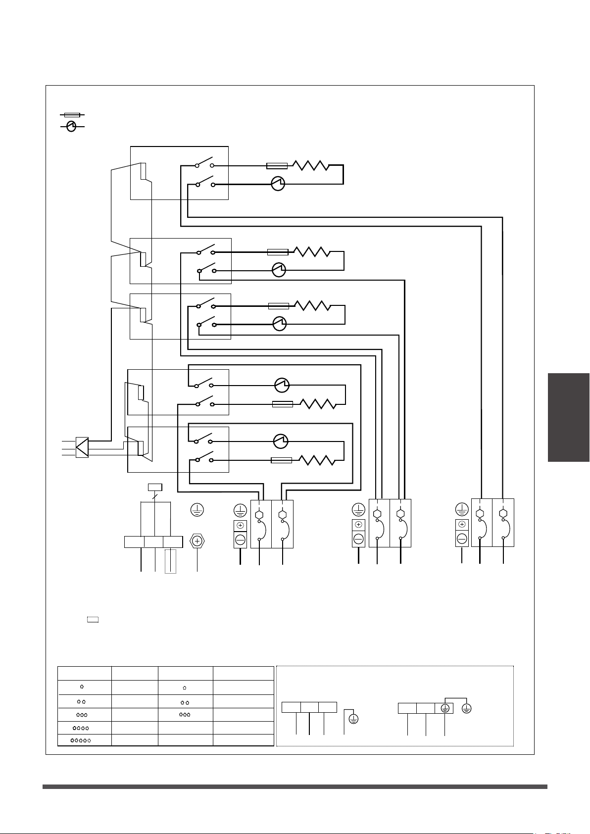
Electric auxiliary heang wiring diagram
: thermal cut-out
: thermal link, self-reseng
25KW HEAT KIT
Round hole number
Relay number
RELAY 1
RELAY 2
Relay number
RELAY 1
RELAY 2
CB3
Round hole number
RELAY 3
CB2
RELAY 4
RELAY 5
CB1
3(S)
1(L1)
2(L2)
TYPE A
L1
L2
TYPE B
Y/G
Circuit breaker number
NOTE2:
Please aach the nameplate to the cover of
the electric control box. All the round holes
located on the plate represent numbers. Please
refer to the Installaon Manual for details.
NOTE1
:
This symbol indicates the element is
oponal, The wiring type of the actual
unit shall prevail.
NOTE3: TO BE WIRED IN ACCORDANCE
WITH NEC AND LOCAL CODES.
NOTE4: POWER A,B,C,D ARE DIFFERENT
POWERS.
Y/G
3(S)
RED
1(L1)
2(L2)
YELLOW
BLACK
3
RED
BLACK
BLACK
BLACK
BLACK
RELAY5
0
4
0
4
BLACK
BLACK
BLACK
RED
RED
RED
RED
RED
RED
BLACK
BLUE
RED
RELAY3
RELAY4
RELAY2
RELAY1
Aux-Heat
control signal
0
1
2 4
0
1
2 4
0
1
2 4
0
1
2 4
0
1
2
4
6 8
0
1
2
4
6 8
0
1
2
4
6 8
0
1
2
4
6 8
0
1
2
4
6 8
0
1
2
4
6 8
0
1
2
4
6 8
0
1
2
4
6 8
0
1
2 4
0
1
2 4
0
1
2 4
0
1
2 4
0
1
2
4
6 8
0
1
2
4
6 8
0
1
2
4
6 8
0
1
2
4
6 8
0
1
2
4
6 8
0
1
2
4
6 8
0
1
2
4
6 8
0
1
2
4
6 8
0
2
4
8
0
2
4
8
0
2
4
8
0
2
4
8
0
1
4
0
1
4
0
1
4
0
1
4
0
1
4
0
1
4
0
1
0
1
0
2
4
8
0
2
4
8
0
2
4
8
0
2
4
8
0
1
0
1
0
1
0
1
0
1
0
1
0
1
0
1
0
2
4
8
0
2
4
8
0
2
4
8
0
2
4
8
0
1
0
1
0
1
0
1
0
1
0
1
0
1
0
1
0
2
4
8
0
2
4
8
0
2
4
8
0
4
8
0
1
0
1
0
1
0
1
0
1
0
1
0
1
0
24V~
TO INDOOR UNIT
MAINBOARD
CN12
TO INDOOR UNIT
MAINBOARD
CN11
BLACK
BLACK
RED
RED
RED
BLACK
8888888888888888
6666666666666666
222222222222222
BLACK
BLACK
1111111111111111111111111111111
1111111111111111111111111111111
6666666666666666
8888888888888888
22222222
8888888888888888
6666666666666666
6666666666666666
L1
L2
CB1
L2
L1
CB CB
L1
L2
CB2
L2
L1
CB CB
L1
L2
CB3
L2
L1
CB CB
RED
BLACK
HTR5
TCO5
TL5
RED
BLACK
HTR4
TCO4
TL4
RED
BLACK
HTR3
TCO3
TL3
HTR1
TCO1
TL1
HTR2
TCO2
TL2
POWER A POWER B
POWER C
POWER D
Y/G
(green)
Y/G
Y/G
Y/G
The wiring mode of power supply A shall be based on the type of original
wiring terminal of AHU; for type A, S posion must be connected to the
ourdoor S; for type B, S posion shall not be connected.
Loading ...
Loading ...
Loading ...