
i
Trademarks
Autel
®
, MaxiCheck
®
, MaxiDAS
®
, MaxiDiag
®
, MaxiRecorder
®
, MaxiScan
®
,
MaxiSys
®
and MaxiTPMS
®
are trademarks of Autel Intelligent Technology Corp.,
Ltd., registered in China, the United States and other countries. All other marks are
trademarks or registered trademarks of their respective holders.
Copyright Information
No part of this manual may be reproduced, stored in a retrieval system or transmitted,
in any form or by any means, electronic, mechanical, photocopying, recording, or
otherwise, without the prior written permission of Autel.
Disclaimer of Warranties and Limitation of Liabilities
All information, specifications and illustrations in this manual are based on the latest
information available at the time of printing.
Autel reserves the right to make changes at any time without notice. While
information of this manual has been carefully checked for accuracy, no guarantee is
given to the completeness and correctness of the contents, including but not limited
to the product specifications, functions, and illustrations.
Autel will not be liable for any direct damages or for any special, incidental, or
indirect damages or for any economic consequential damages (including lost profits).
For Services and Support:
http://pro.autel.com
www.autel.com
1-855-288-3587/1-855-AUTELUS (North America)
0086-755-86147779 (China)
For technical assistance in all other markets, please contact your local selling agent.

ii
Safety Precautions and Warnings
To prevent personal injury or damage to vehicles and/or the scan
tool, read this instruction manual first and observe the following
safety precautions whenever working on a vehicle:
Always perform automotive testing in a safe environment.
Wear safety eye protection that meets ANSI standards.
Keep clothing, hair, hands, tools, test equipment, etc. away from
all moving or hot engine parts.
Operate the vehicle in a well-ventilated work area: Exhaust gases
are poisonous.
Put blocks in front of the drive wheels and never leave the vehicle
unattended while running tests.
Be extra cautious when working around the ignition coil,
distributor cap, ignition wires and spark plugs. These components
create hazardous voltages when the engine is running.
Put the transmission in PARK (for automatic transmission) or
NEUTRAL (for manual transmission) and make sure the parking
brake is engaged.
Keep a fire extinguisher suitable for gasoline/chemical/ electrical
fires nearby.
Don’t connect or disconnect any test equipment while the ignition
is on or the engine is running.
Keep the scan tool dry, clean, free from oil/water or grease. Use
a mild detergent on a clean cloth to clean the outside of the scan
tool, when necessary.

iii
Table of Contents
1. USING THE MANUAL ................................................................................... 1
1.1 CONVENTIONS ................................................................................................... 1
2. GENERAL INFORMATION .......................................................................... 2
2.1 ON-BOARD DIAGNOSTICS (OBD) II ................................................................. 2
2.2 DIAGNOSTIC TROUBLE CODES (DTCS) ............................................................ 2
2.3 LOCATION OF THE DATA LINK CONNECTOR (DLC) ........................................ 3
2.4 OBD II READINESS MONITORS ........................................................................ 4
2.5 OBD II MONITOR READINESS STATUS ............................................................. 5
2.6 OBD II DEFINITIONS ........................................................................................ 6
3. USE THE SCAN TOOL .................................................................................. 8
3.1 TOOL DESCRIPTION .......................................................................................... 8
3.2 SPECIFICATIONS .............................................................................................. 10
3.3 ACCESSORIES INCLUDED ................................................................................ 10
3.4 KEYBOARD ...................................................................................................... 10
3.5 POWER ............................................................................................................ 10
3.6 SYSTEM SETUP ................................................................................................ 11
3.7 VEHICLE COVERAGE ...................................................................................... 14
3.8 PRODUCT TROUBLESHOOTING ....................................................................... 15
4. PLAYBACK DATA ....................................................................................... 16
4.1 REVIEW DATA ................................................................................................. 16
4.2 DELETE DATA ................................................................................................. 17
4.3 PRINT DATA .................................................................................................... 17
5. DIAGNOSTICS .............................................................................................. 18
5.1 ENTER VEHICLE INFORMATION ...................................................................... 18
5.2 DIAGNOSTIC TEST ........................................................................................... 23
5.3 DIAGNOSTIC OPERATION ................................................................................ 27
6. OBD II DIAGNOSTICS ................................................................................ 33
6.1 READ CODES ................................................................................................... 34

iv
6.2 ERASE CODES ................................................................................................. 37
6.3 LIVE DATA ...................................................................................................... 39
6.4 FREEZE FRAME ............................................................................................... 44
6.5 RETRIEVE I/M READINESS STATUS ................................................................ 45
6.6 O2 MONITOR TEST ......................................................................................... 47
6.7 ON-BOARD MONITOR TEST ............................................................................ 49
6.8 COMPONENT TEST .......................................................................................... 52
6.9 VIEW VEHICLE INFORMATION ........................................................................ 53
6.10 MODULES PRESENT ....................................................................................... 55
6.11 DTC LOOKUP ................................................................................................ 55
7. OIL RESET .................................................................................................... 57
7.1 GENERAL INFORMATION ................................................................................ 57
7.2 RESET OPERATION.......................................................................................... 57
8. EPB .................................................................................................................. 65
8.1 EPB SAFETY ................................................................................................... 65
8.2 EPB MAINTENANCE ....................................................................................... 65
8.3 ABS MAINTENANCE ....................................................................................... 73
9. PRINT DATA ................................................................................................. 76
10. SOFTWARE UPDATE .................................................................................. 78
10.1 REGISTER THE TOOL ..................................................................................... 78
10.2 UPDATE PROCEDURE ..................................................................................... 81
10.3 VIEW OR DELETE PROGRAMS ....................................................................... 85
11. WARRANTY AND SERVICE ...................................................................... 87
11.1 LIMITED ONE YEAR WARRANTY .................................................................. 87
11.2 SERVICE PROCEDURES .................................................................................. 87

1
1. Using the Manual
This manual contains device usage instructions.
Some illustrations shown in this manual may contain modules and
optional equipment that are not included on your system. Contact your
sales representative for availability of other modules and optional
tools or accessories.
1.1 Conventions
The following conventions are used.
Bold Text
Bold emphasis is used to highlight selectable items such as buttons
and menu options.
Example:
Tap OK.
Terminology
The term “select” means highlighting a button or menu item and
tapping it to confirm the selection.
Notes and Important Messages
The following messages are used.
Notes
A NOTE provides helpful information such as additional explanations,
tips, and comments.
Important
IMPORTANT indicates a situation which, if not avoided, may result
in damage to the test equipment or vehicle.
Illustrations
Illustrations used in this manual are samples, the actual testing screen
may vary for each vehicle being tested. Observe the menu titles and
on-screen instructions to make correct option selection.

2
2. General Information
2.1 On-Board Diagnostics (OBD) II
The first generation of On-Board Diagnostics (called OBD I) was
developed by the California Air Resources Board (ARB) and
implemented in 1988 to monitor some of the emission control
components on vehicles. As technology evolved and the desire to
improve the On-Board Diagnostic system increased, a new generation
of On-Board Diagnostic system was developed. This second generation
of On-Board Diagnostic regulations is called "OBD II".
The OBD II system is designed to monitor emission control systems
and key engine components by performing either continuous or
periodic tests of specific components and vehicle conditions. When a
problem is detected, the OBD II system turns on a warning lamp (MIL)
on the vehicle instrument panel to alert the driver typically by the
phrase of “Check Engine” or “Service Engine Soon”. The system will
also store important information about the detected malfunction so
that a technician can accurately find and fix the problem. Here below
are three pieces of such valuable information:
1) Whether the Malfunction Indicator Light (MIL) is
commanded 'on' or 'off';
2) Which, if any, Diagnostic Trouble Codes (DTCs) are stored;
3) Readiness Monitor status.
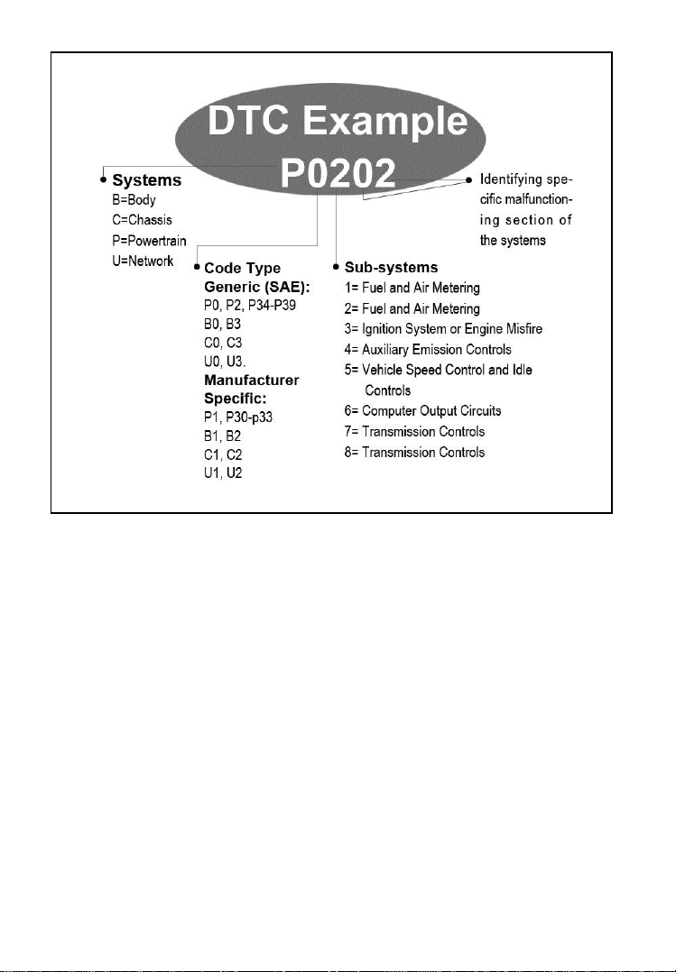
2.2 Diagnostic Trouble Codes (DTCs)
OBD II Diagnostic Trouble Codes are codes that are stored by the on-
board computer diagnostic system in response to a problem found in
the vehicle. These codes identify a particular problem area and are
intended to provide you with a guide as to where a fault might be
occurring within a vehicle. OBD II Diagnostic Trouble Codes consists
of a five-digit alphanumeric code. The first character, a letter,
identifies which control system sets the code. The other four
characters, all numbers, provide additional information on where the
DTC originated and the operating conditions that caused it to set. Here
below is an example to illustrate the structure of the digits:
3
2.3 Location of the Data Link Connector (DLC)
The DLC (Data Link Connector or Diagnostic Link Connector) is the
standardized 16-cavity connector where diagnostic scan tools
interface with the vehicle's on-board computer. The DLC is usually
located 12 inches from the center of the instrument panel (dash), under
or around the driver’s side for most vehicles. If Data Link Connector
is not located under dashboard, a label should be there telling location.
For some Asian and European vehicles, the DLC is located behind the
ashtray and the ashtray must be removed to access the connector. If
the DLC cannot be found, refer to the vehicle’s service manual for the
location.

4
2.4 OBD II Readiness Monitors
An important part of a vehicle’s OBD II system is the Readiness
Monitors, which are indicators used to find out if all of the emissions
components have been evaluated by the OBD II system. They are
running periodic tests on specific systems and components to ensure
that they are performing within allowable limits.
Currently, there are eleven OBD II Readiness Monitors (or I/M
Monitors) defined by the U.S. Environmental Protection Agency
(EPA). Not all monitors are supported by all vehicles and the exact
number of monitors in any vehicle depends on the motor vehicle
manufacturer’s emissions control strategy.
Continuous Monitors -- Some of the vehicle components or systems
are continuously tested by the vehicle’s OBD II system, while others
are tested only under specific vehicle operating conditions. The
continuously monitored components listed below are always ready:
1) Misfire
2) Fuel System
3) Comprehensive Components (CCM)
Once the vehicle is running, the OBD II system is continuously
checking the above components, monitoring key engine sensors,
watching for engine misfire, and monitoring fuel demands.
Non-Continuous Monitors -- Unlike the continuous monitors, many
emissions and engine system components require the vehicle to be
operated under specific conditions before the monitor is ready. These
monitors are termed non-continuous monitors. For different ignition
type engines, the available monitors are different too.
The following monitors are to be used for spark ignition engines only:

5
1) EGR System
2) O2 Sensors
3) Catalyst
4) Evaporative System
5) O2 Sensor Heater
6) Secondary Air
7) Heated Catalyst
The following monitors are to be used for compression ignition
engines only:
1) EGR System
2) NMHC Catalyst
3) NOx Aftertreatment
4) Boost Pressure System
5) Exhaust Gas Sensor
6) PM Filter
2.5 OBD II Monitor Readiness Status
OBD II systems must indicate whether or not the vehicle’s PCM’s
monitor system has completed testing on each component.
Components that have been tested will be reported as “Ready”, or
“Complete”, meaning they have been tested by the OBD II system.
The purpose of recording readiness status is to allow inspectors to
determine if the vehicle’s OBD II system has tested all the
components and/or systems.
The power-train control module (PCM) sets a monitor to “Ready” or
“Complete” after an appropriate drive cycle has been performed. The
drive cycle that enables a monitor and sets readiness codes to “Ready”
varies for each individual monitor. Once a monitor is set as “Ready”
or “Complete”, it will remain in this state. A number of factors,
including erasing of diagnostic trouble codes (DTCs) with a scan tool
or a disconnected battery, can result in Readiness Monitors being set
to “Not Ready”. Since the three continuous monitors are constantly
evaluating, they will be reported as “Ready” all of the time. If testing
of a particular supported non-continuous monitor has not been

6
completed, the monitor status will be reported as “Not Complete” or
“Not Ready.”
In order for the OBD monitor system to become ready, the vehicle
should be driven under a variety of normal operating conditions.
These operating conditions may include a mix of highway driving and
stop and go, city type driving, and at least one overnight-off period.
For specific information on getting your vehicle’s OBD monitor
system ready, please consult your vehicle owner’s manual.
2.6 OBD II Definitions
Power-train Control Module (PCM) -- OBD II terminology for the
on-board computer that controls engine and drive train.
Malfunction Indicator Light (MIL) -- Malfunction Indicator Light
(Service Engine Soon, Check Engine) is a term used for the light on
the instrument panel. It is to alert the driver and/or the repair
technician that there is a problem with one or more of vehicle's
systems and may cause emissions to exceed federal standards. If the
MIL illuminates with a steady light, it indicates that a problem has
been detected and the vehicle should be serviced as soon as possible.
Under certain conditions, the dashboard light will blink or flash. This
indicates a severe problem and flashing is intended to discourage
vehicle operation. The vehicle onboard diagnostic system can not turn
the MIL off until necessary repairs are completed or the condition no
longer exists.
DTC -- Diagnostic Trouble Code (DTC) that identifies which section
of the emission control system has malfunctioned.
Enabling Criteria -- Also termed Enabling Conditions. They are the
vehicle-specific events or conditions that must occur within the engine
before the various monitors will set, or run. Some monitors require the
vehicle to follow a prescribed “drive cycle” routine as part of the
enabling criteria. Drive cycles vary among vehicles and for each
monitor in any particular vehicle.
OBD II Drive Cycle -- A specific mode of vehicle operation that
provides conditions required to set all the readiness monitors
applicable to the vehicle to the “Ready” condition. The purpose of

7
completing an OBD II drive cycle is to force the vehicle to run its
onboard diagnostics. Some form of a drive cycle needs to be
performed after DTCs have been erased from the PCM’s memory or
after the battery has been disconnected. Running through a vehicle’s
complete drive cycle will “set” the readiness monitors so that future
faults can be detected. Drive cycles vary depending on the vehicle and
the monitor that needs to be reset. For vehicle specific drive cycle,
consult the vehicle’s Owner’s Manual.
Freeze Frame Data -- When an emission related fault occurs, the
OBD II system not only sets a code but also records a snapshot of the
vehicle operating parameters to help in identifying the problem. This
set of values is referred to as Freeze Frame Data and may include
important engine parameters such as engine RPM, vehicle speed, air
flow, engine load, fuel pressure, fuel trim value, engine coolant
temperature, ignition timing advance, or closed loop status.
8
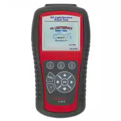
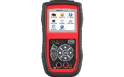
3. Use the Scan Tool
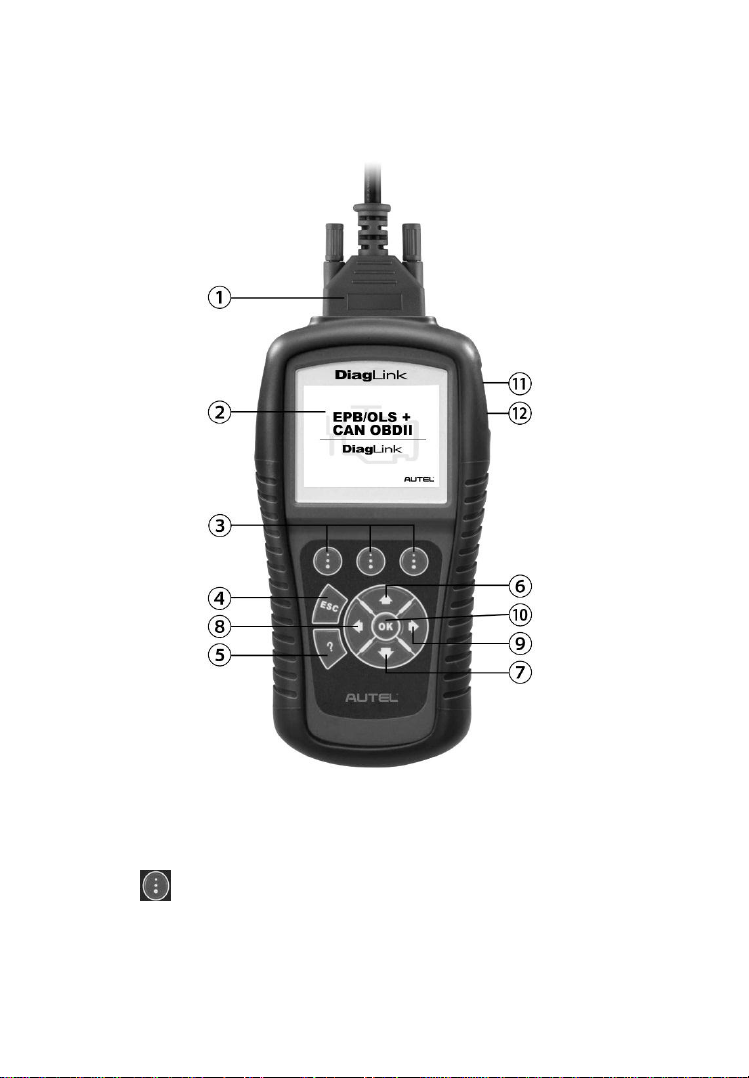
3.1 Tool Description
1) CONNECTOR -- Connects the scan tool to the vehicle’s Data
Link Connector (DLC).
2) LCD DISPLAY -- Indicates test results.
3) FUNCTION BUTTONS – Corresponds with “buttons” on
screen for executing commands.

9
4) ESC BUTTON -- Cancels a selection (or an action) from a
menu or returns to the previous screen.
5) HELP BUTTON -- Provides help information and the
description of DTCs.
6) UP SCROLL BUTTON -- Moves up through menu and
submenu items in menu mode. When more than one screen of
data is retrieved, moves up through the current screen to the
previous screens for additional data. When looking up DTC, it is
used to change value of selected character.
7) DOWN SCROLL BUTTON -- Moves down through
menu and submenu items in menu mode. When more than one
screen of data is retrieved, moves down through the current
screen to next screens for additional data. When looking up DTC,
it is used to change value of selected character.
8) LEFT SCROLL BUTTON -- When look up DTC
definitions, moves to previous character and views additional
information on previous screens if DTC definition covers more
than one screen; views previous screen or previous frames of
recorded data. It is also used to view previous trouble code when
viewing DTCs.
9) RIGHT SCROLL BUTTON -- When look up DTC
definitions, moves to next character and view additional
information on next screens if DTC definition covers more than
one screen; views next screen or next frames of recorded data. It
is also used to view next trouble code when viewing DTCs.
10) OK BUTTON -- Confirms a selection (or an action) from a
menu.
11) USB CONNECTOR -- Connects the scan tool to the PC for
printing.
12) TF CARD SLOT – Holds the System TF card.

10
3.2 Specifications
1) Display: 2.8" TFT color display (320 x 240 dpi)
2) Operating Temperature: 0 to 60°C (32 to 140 °F)
3) Storage Temperature: -20 to 70°C (-4 to 158 °F)
4) External Power: 12.0 V to 18.0 V power provided via vehicle
battery.
5) Dimensions:
Length Width Height
198.5 mm (7.81”) 103.8 mm (4.09”) 37.5 mm (1.48”)
6) Weight: 0.28 kg (w/o main cable) 0.435 kg (with main cable)
3.3 Accessories Included
1) User Manual -- Instructions on tool operations.
2) OBD II Cable -- Provides power to tool and communicates
between the tool and the vehicle.
3) USB Cable -- Used to upgrade the scan tool, and to print retrieved
data.
4) TF Card -- Contains the scan tool’s operation software and
applications.
5) Carry Case -- A nylon case to store the scan tool.
3.4 Keyboard
No solvents such as alcohol are allowed to clean the keypad or display.
Use a mild nonabrasive detergent and a soft cotton cloth. Do not soak
the keypad as the keypad is not waterproof.
3.5 Power
The scan tool is powered via the Data Link Connector (DLC). Just
follow the steps below to turn on the scan tool:
1) Connect the OBD II cable to scan tool.
2) Find DLC on vehicle.
A plastic DLC cover may be found for some vehicles and you
need to remove it before plugging the OBD II cable.
11
3) Plug the OBD II cable to the vehicle’s DLC.
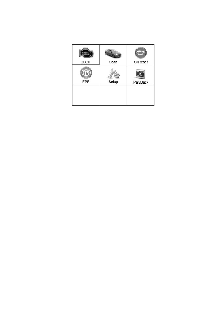
4) Power up the scan tool, and wait for the Main Screen to appear
(Figure 3.1).
Figure 3.1
3.6 System Setup
The System Setup functions allow you to adjust default settings and
view information about the scan tool.
1) Language: Selects the desired language.
2) Unit of Measure: Sets the unit of measure to English or Metric.
3) Beep Set: Turns on/off the beep.
4) Key Test: Checks if the keyboard is working properly.
5) LCD Test: Checks if the LCD display is working properly.
6) About: Provides information of the scan tool.
Settings of the unit will remain until change to the existing
settings is made.
To Enter the Setup Menu
From the Main Screen, use LEFT/RIGHT scroll button or
UP/DOWN scroll button to select Setup, and press the OK button.
Following the instructions to do adjustments and settings could make
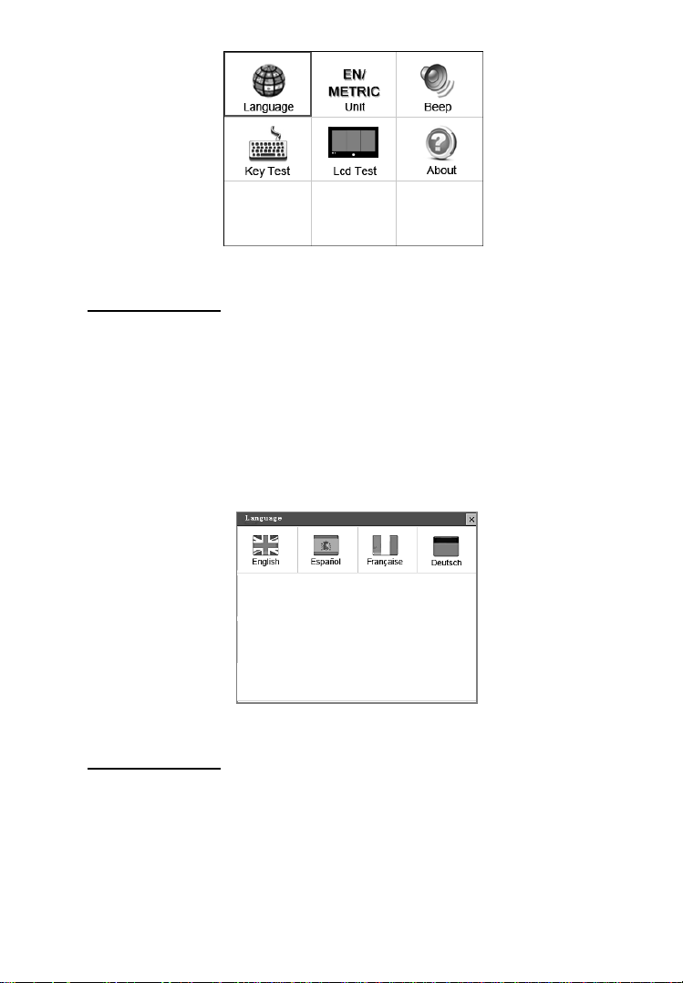
your diagnosis more conveniently and easily (Figure 3.2).
12
Figure 3.2
Language Setup
English is the default language.
1) From System Setup screen, use the LEFT/RIGHT scroll button
to select Language, and press the OK button.
2) Use the LEFT/RIGHT scroll button to select the desired
language and press the OK button to save your selection and
return to previous screen (Figure 3.3).
Figure 3.3
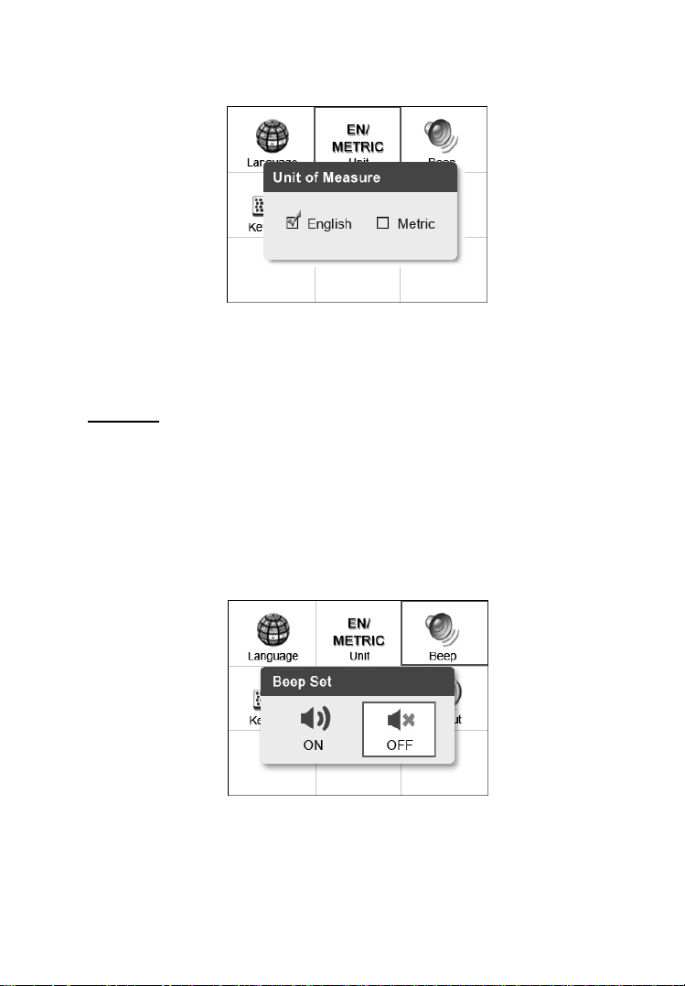
Unit of Measure
Metric is the default measurement unit.
1) From System Setup screen, use the LEFT/RIGHT scroll button
to select EN/METRIC Unit and press the OK button.
13
2) From Unit of Measure screen, use the LEFT/RIGHT scroll
button to select the desired unit of measurement (Figure 3.4).
Figure 3.4
3) Press the OK button to save your selection and return to previous
menu. Or, press the ESC button to exit without saving.
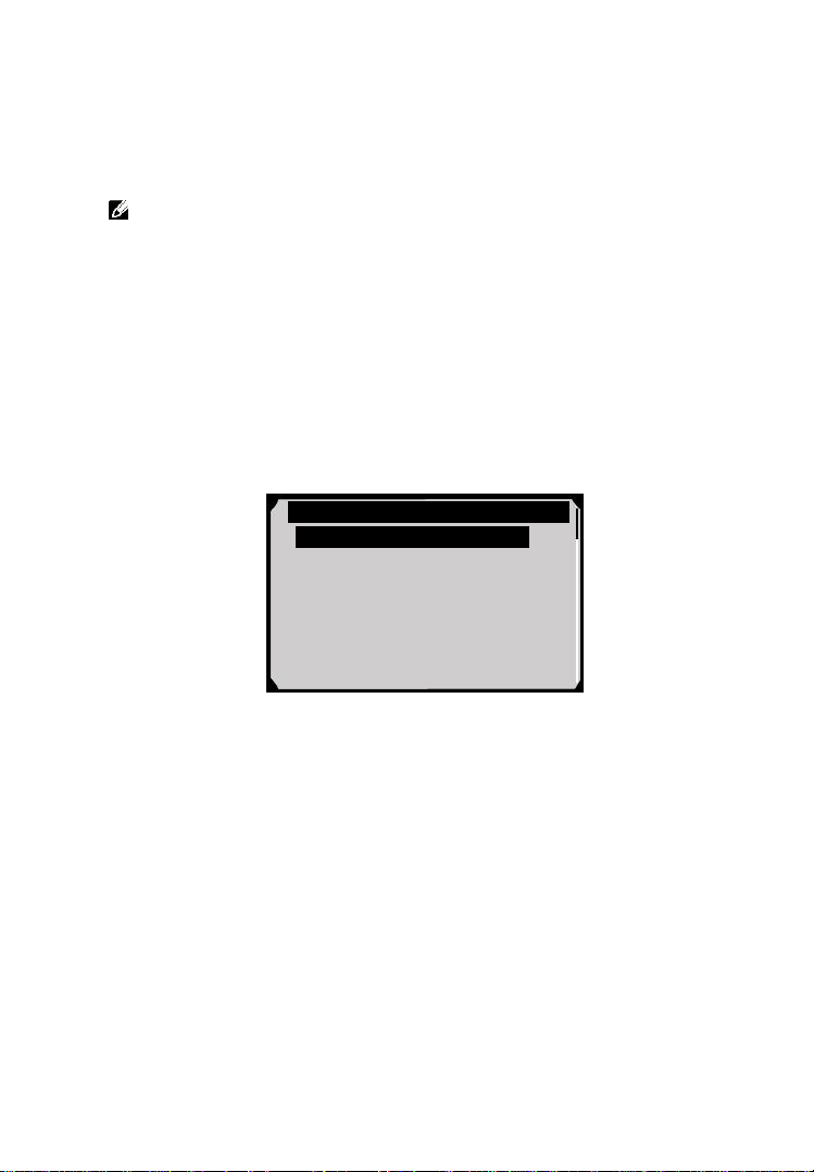
Beep Set
The default setting is Beep On.
1) From System Setup screen, use the UP/DOWN scroll button or
the LEFT/RIGHT scroll button to select Beep and press the OK
button.
2) From Beep Set menu, use the LEFT/RIGHT scroll button to
select ON or OFF to turn on/off the beep (Figure 3.5).
Figure 3.5
3) Press the OK button to save your selection and return to the
previous menu. Or, press the ESC button to exit without saving.

14
Key Test
The Key Test function checks if the keyboard is working properly.
1) From System Setup screen, use the UP/DOWN scroll button or
the LEFT/RIGHT scroll button to select Key Test, and press the
OK button.
2) Press any key to start test. When you press a key, the edge around
corresponding key on the screen should turn to red. Otherwise,
the key is not functioning properly.
3) Double press ESC to return to the previous menu.
LCD Test
The LCD Test function checks if the LCD display is working normally.
1) From System Setup screen, use the UP/DOWN scroll button or
the LEFT/RIGHT scroll button to select LCD Test, and press
the OK button.
2) Look for missing spots in the red, green, blue, black and white
LCD display.
3) When completed, press the ESC button to exit.
About
The About function allows viewing of some important information
such as serial number and software version number of the scanner.
1) From System Setup screen, use the UP/DOWN scroll button or
the LEFT/RIGHT scroll button to select About and press the
OK button; wait for the About screen to appear.
2) View tool information on screen. Press the ESC button to exit.
3.7 Vehicle Coverage
On the basis of all OBD II compliant vehicles, including those
equipped with universal protocol -- Control Area Network (CAN),
DiagLink scanner expands vehicle system coverage and offers more
diagnostic power to the vehicle technicians. Featuring expanded
global vehicle coverage, the scan tool offers technicians a significant
improvement on model years covered by supported manufactures.

15
3.8 Product Troubleshooting
Vehicle Linking Error
A communication error occurs if the scan tool fails to communicate
with the vehicle’s ECU (Electronic Control Unit). You need to do the
following to check up:
Verify that the ignition is ON.
Check if the scan tool’s connector is securely
connected to the vehicle’s DLC.
Turn the ignition off and wait for about 10 seconds. Turn the
ignition back to on and continue the testing.
Verify the control module is not defective.
Operating Error
If the scan tool freezes, then an exception occurs or the vehicle’s ECU
(Electronic Control Unit) is too slow to respond to requests. You need
to do the following to reset the tool:
Reset the scan tool.
Turn the ignition off and wait for about 10 seconds. Turn the
ignition back to on and continue the testing.
Scan Tool Doesn’t Power up
If the scan tool won’t power up or operates incorrectly in any other
way, you need to do the following to check up:
Check if the scan tool’s connector is securely connected to the
vehicle’s DLC;
Check if the DLC pins are bent or broken. Clean the DLC pins if
necessary.
Check vehicle battery to make sure it is still good with at least
8.0 volts.
16
4. Playback Data
The Playback Data function allows viewing data from last test
recorded by the scan tool.
NOTE: The amount of files that can be saved depends on the
space available in the TF card.
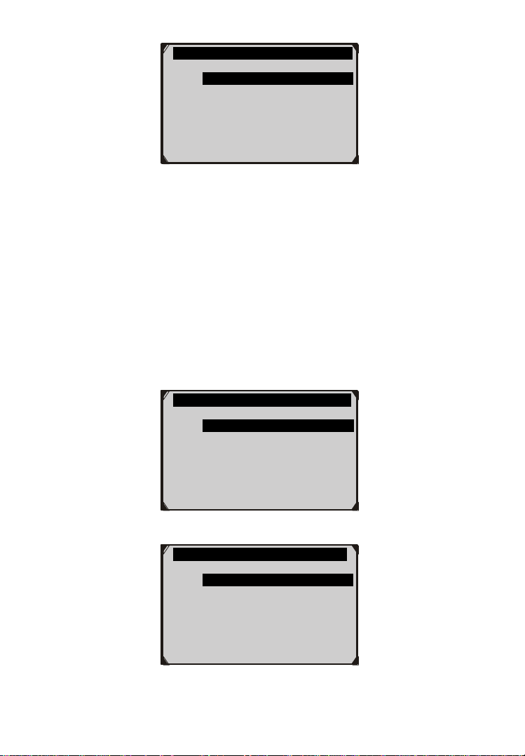
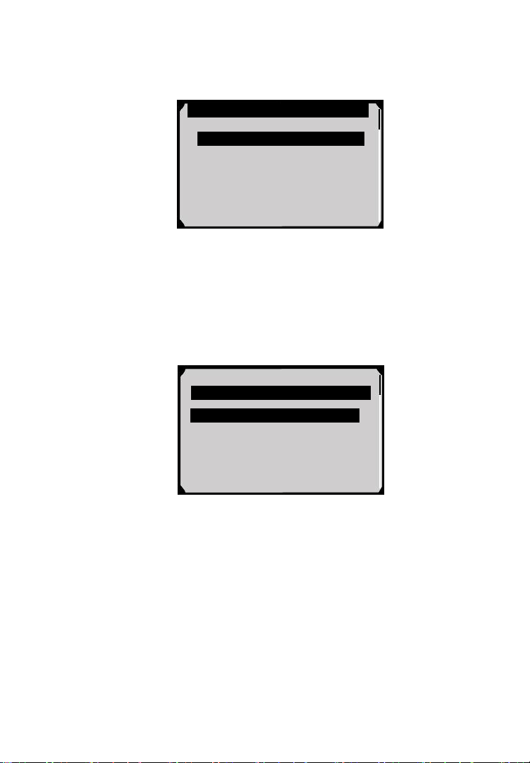
4.1 Review Data
1) Use the LEFT/RIGHT scroll button or the UP/DOWN scroll
button to select Playback from Main Screen (Figure 3.1), and
press the OK button. Wait for the Review Data screen to appear
(Figure 4.1).
2) Use the UP/DOWN scroll button to select the desired item from
Review Data screen, and press the OK button.
Figure 4.1
If no data from previously tested vehicle is recorded, a message
“No data available!” shows on the screen.
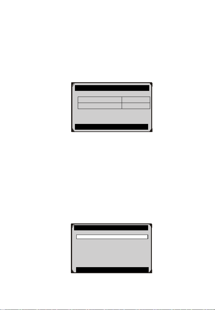
3) Review selected data on screen (Figure 4.2).
Review Data
1. EPB

17
Figure 4.2
4.2 Delete Data
By selecting Delete on the screen, you are allowed to erase the selected
data on the scan tool. Review the recordings thoroughly before erasing.
You could also erase all recordings by select Delete All.
NOTE: Don’t use Delete All unless you are definitely sure what
you are going to proceed.
4.3 Print Data
Print option allows you to print the recorded files to your computer
and then to the printer.
For more details, please refer to chapter 9. Print Data.
Vehicle Specification
Vehicle: Mustang
Engine Type: Other
Capacity: 3.8L
Transmission: Manual
Fuel Type: Gasoline
Emission Level: Federal Emission
VIN:1FAFP40462F100819
PrefSuf:2R3APB VersionID:4612
Print

18
5. Diagnostics
NOTE: The screens shown below in this chapter are examples.
The screens actually appear vary by vehicle.
5.1 Enter Vehicle Information
Before using the scan tool to diagnose, you must input the vehicle
information. There are generally three ways to input the vehicle
information.
Vehicle information manual acquisition.
VIN code automatic acquisition.
VIN code manual acquisition.
The way to enter diagnostic procedure depends on vehicle being tested.
5.1.1 Vehicle Information Manual Acquisition
Follow these steps to enter the vehicle information and begin
diagnostics. (Take Ford as an example)
1) Connect the scan tool to the vehicle’s DLC via the main cable
and wait for the Main Screen to appear.
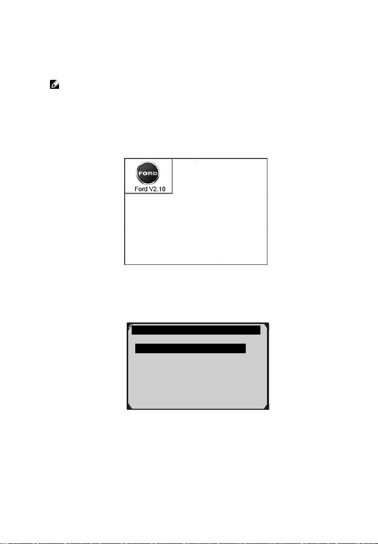
2) Select Scan icon in the Main Screen (Figure 3.1) and wait for
the vehicle manufacturer screen and then select the vehicle make.
Figure 5.1
19
Figure 5.2
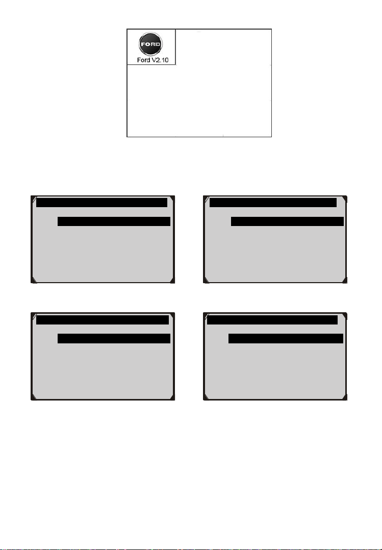
3) Step by step, select the right options for your vehicle according to
each screen that appears.
Figure 5.3 Figure 5.4
Figure 5.5 Figure 5.6
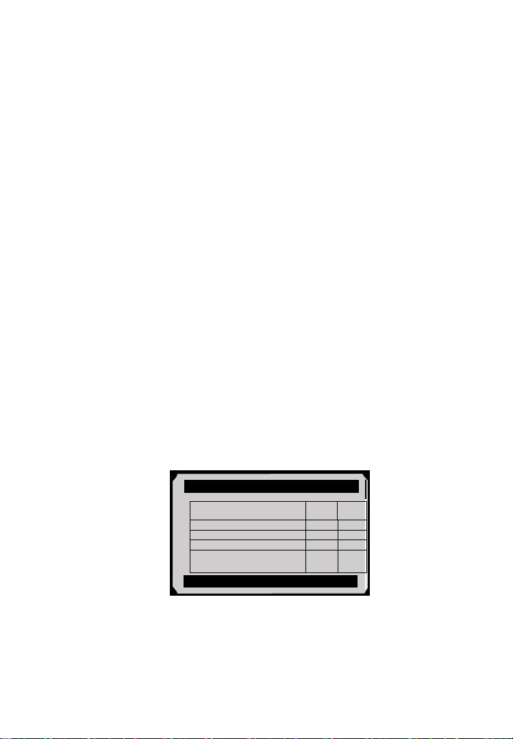
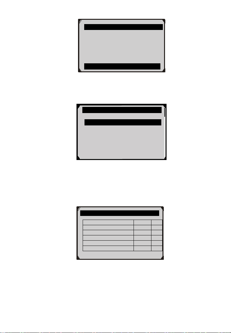
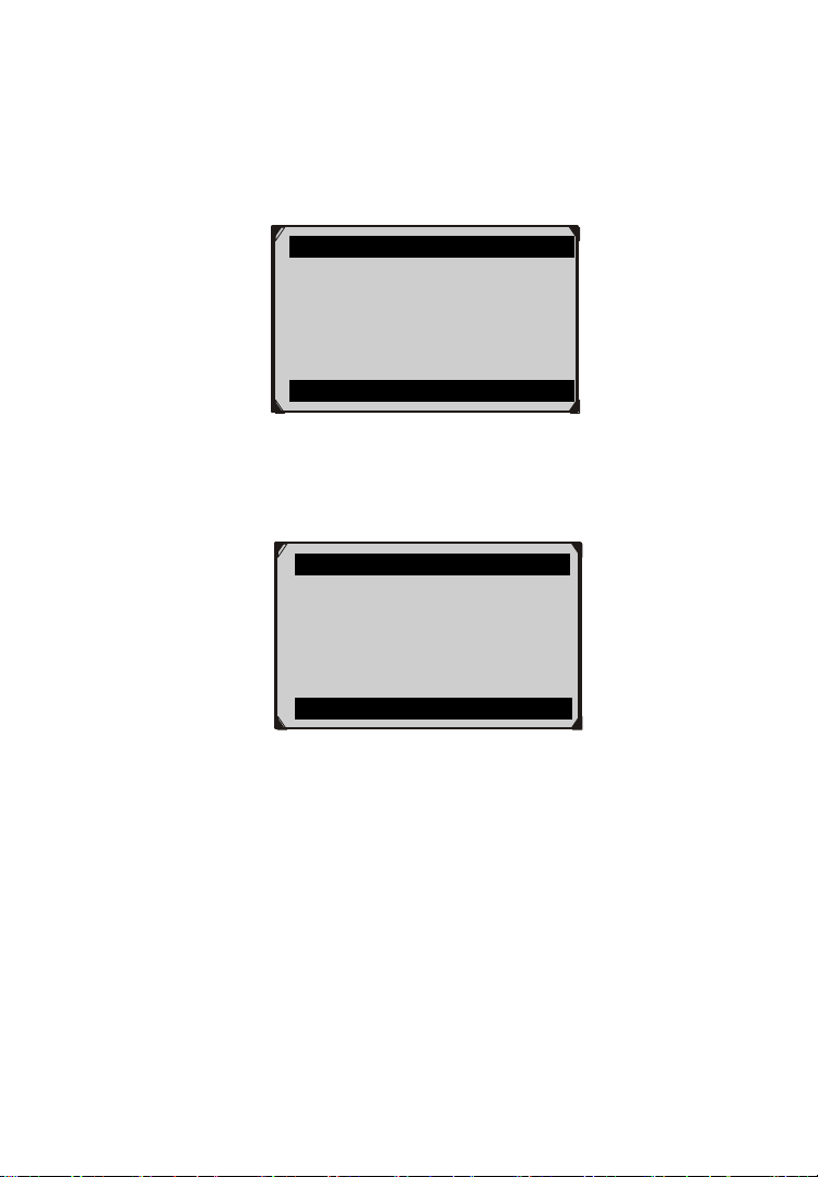
4) Do this until the complete vehicle information is entered. Then
the scan tool will ask your confirmation.
DAS
1. Start New Session
2. Manual Vehicle Entry
3. Vehicle selection
Vehicle
1. All other
Traction Assist
1. Not Equipped
2. Equipped
Transmission
1. ASM(Auto Shift Manual)
2. Powershift
3. Manual
4. Automatic
5. DPS6
20
Figure 5.7
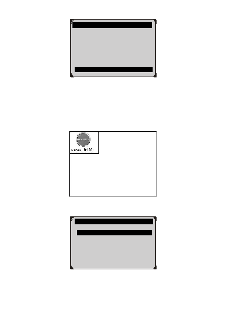
5.1.2 VIN Code Automatic Acquisition
Some vehicles could identify the VIN code intelligently, saving
customer’s time to input complex information. (Take Renault as an
example)
Figure 5.8
Figure 5.9
Vehicle Specification
Vehicle: Mustang
Engine Type: Other
Capacity: 3.8L
Transmission: Manual
Fuel Type: Gasoline
Emission Level: Federal Emission
Is this correct?
Yes no
RENAULT
1. VIN acquisition
21
Figure 5.10
In this mode, the scan tool will communicate with the vehicle and read
off the VIN code automatically. It will ask for your confirmation about
the VIN code if ECU response received. If no response from the ECU,
it will turn to manual mode. (Please see VIN Code Manual
Acquisition)
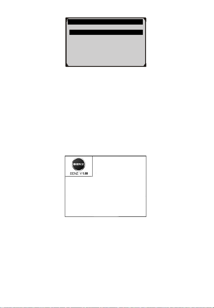
5.1.3 VIN Code Manual Acquisition
For some vehicles, both selecting the options manually and acquiring
the VIN are available for you to enter the vehicle information. (Take
Benz as an example)
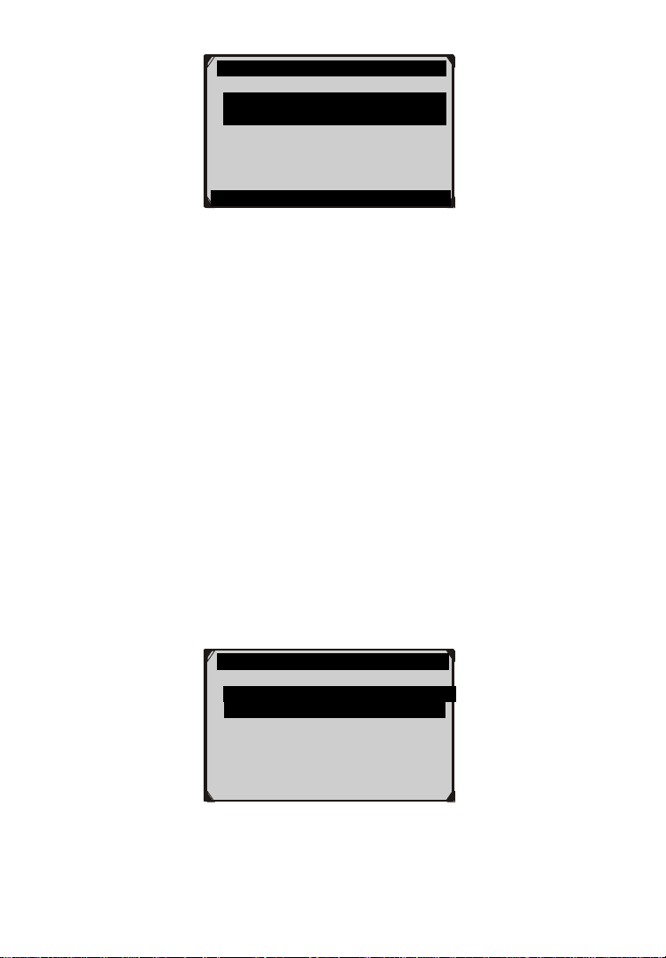
Figure 5.11
In the Benz Cars menu, choose the item “2. Select by entering VIN”
and you can enter the VIN code directly.
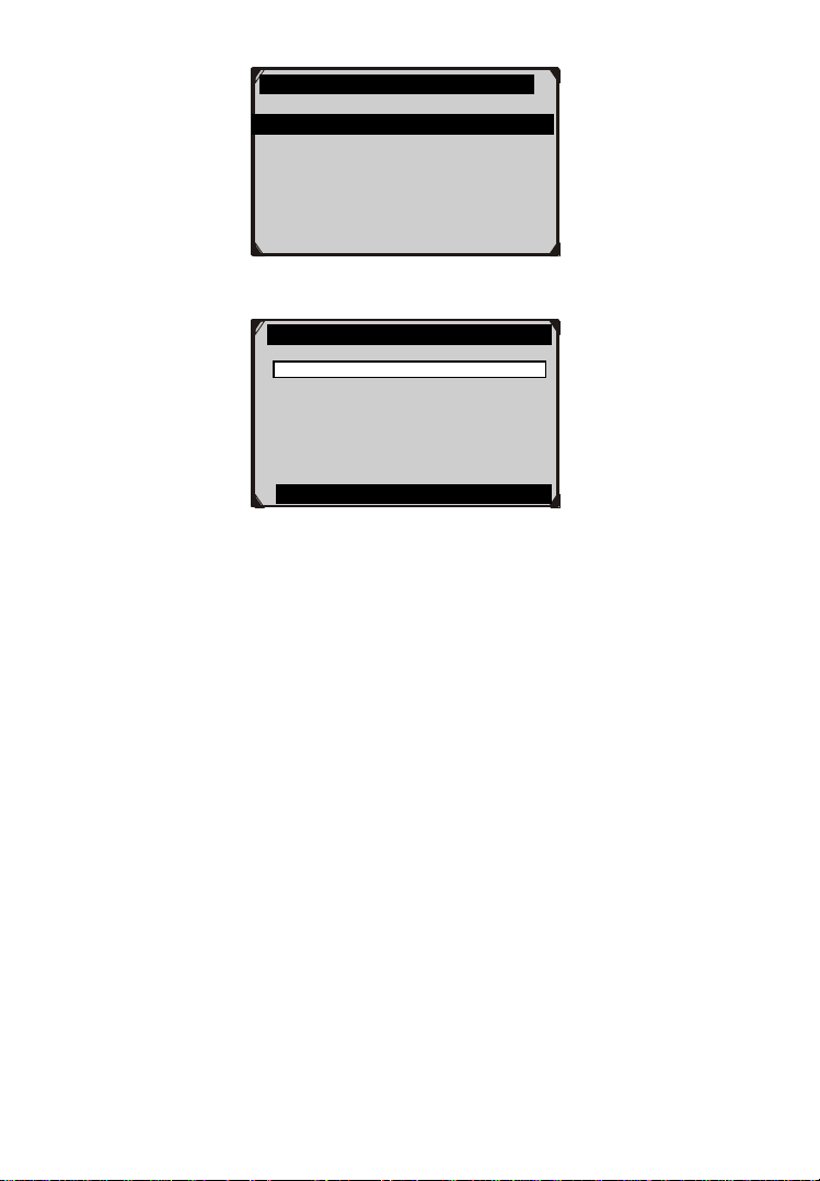
VIN acquisition
1.VIN CODE automatic acquisition
2.VIN CODE manual acquisition
3.Vehicle type manual acquisition
22
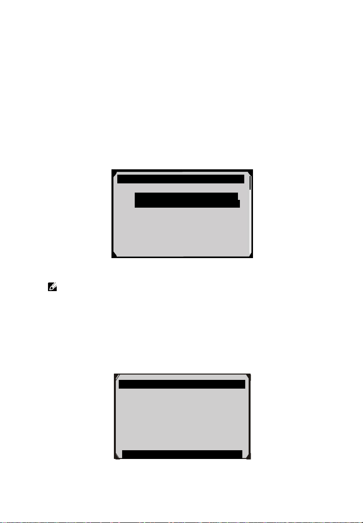
Figure 5.12
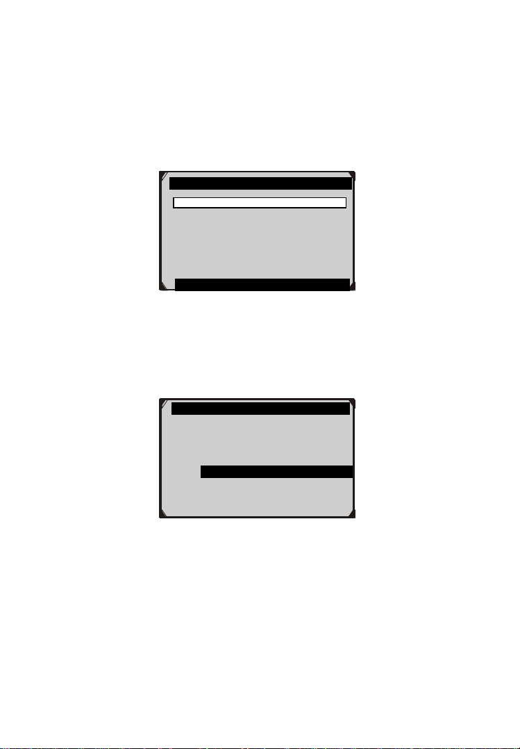
Figure 5.13
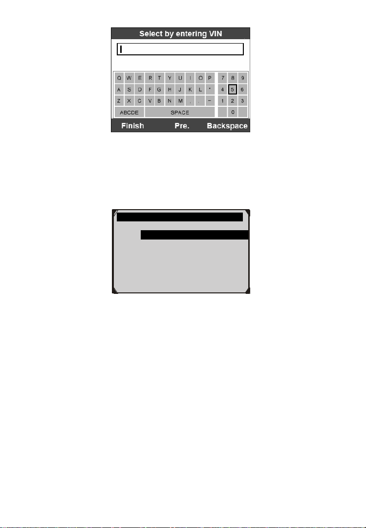
When you choose to enter VIN directly, a pop-up soft keyboard is used
to input VIN code (Figure 5.14).
To pop up the keyboard, press the Function button corresponding to
Show. Use the UP/DOWN scroll button and LEFT/RIGHT scroll
button to select digit and character, and then press the OK button to
confirm. Use Backspace button to delete the previous digit or
character. When finished, press the Function button corresponding to
Finish to proceed. The scan tool will identify the VIN code and turn
to diagnostic procedure.
Cars
1. Vehicle detect
2. Vehicle record and abbreviations
3. All model series
4. A-Class
5. B-Class
6. C-Class/CLK
7. E-Class/CLS
Select by entering VIN
If the chassis number does not
Match the vehicle, enter VIN as a
17-digit code.
Example:WDBNG70J02A123456
Finish Show Esc
23
Figure 5.14
5.2 Diagnostic Test
After you have entered the correct vehicle information, the diagnostic
testing selection will display as below:
Figure 5.15
5.2.1 Auto Scan
Depending on the scan tool model, Auto Scan function will carry out
an overall scan to check the status of all systems or four systems
(engine, transmission, airbag and ABS) on the vehicle being tested.
Selecting Auto Scan will lead to retrieve the trouble codes in each
system of the vehicle one by one. It will take a few minutes to display.
Use the UP/DOWN scroll button to select Auto Scan from Main
Groups menu (Figure 5.15), and press the OK button.
Select An Option
1. Auto Scan
2. Control Unit
3. Vehicle Information
24
Figure 5.16
User is allowed to check the details of each system, quickly erase DTC,
save the data, and display DTC from the Auto Scan menu screen. To
select the options on the bottom, simply press the corresponding
function button.
Save –You can save the Auto Scan information as “Vehicle
Record” so that you will not need to follow the vehicle selection
process again on the same vehicle in later tests. For detailed
instructions, please refer to 5.2.4 Save and retrieve files.
Quick Erase – By selecting this option, the scan tool will erase
all displaying DTCs and once again read the data and check the
latest status of the system. If the system did not repair, the trouble
codes will keep on displaying.
Display DTC – This option allows you to read DTC definitions
in the highlighted system. If more than one fault is detected in a
system, the scan tool will display an option list for you to view
different kind of DTCs or freeze frames.
Figure 5.17
100% Auto Scan
PCM- Powertrain Fault 1
Control Module
Quick Erase Save Display DTC
Select Option
1. CMDTCs(Continuous memory
diagnostic trouble codes)
2. Freeze Frame-Mode 2
3. Pending
25
In Auto Scan screen (Figure 5.16), pressing OK button will turn to
diagnostic operation. For more details, refer to 5.3 Diagnostic
Operation.
To exit the Auto Scan option, press ESC button. The scan tool will
display a message “Are you sure to quit?” to ask for your
confirmation. Select Yes to quit, and select No to cancel command.
5.2.2 Control Unit
Control Unit function will list down all the systems that might be
available on the vehicle for you to select to test. Select a system to
display the function menu and start testing.
Figure 5.18
NOTE: The actual systems displayed in the System Menu
screen may be different from Figure 5.18 due to various vehicle
configurations.
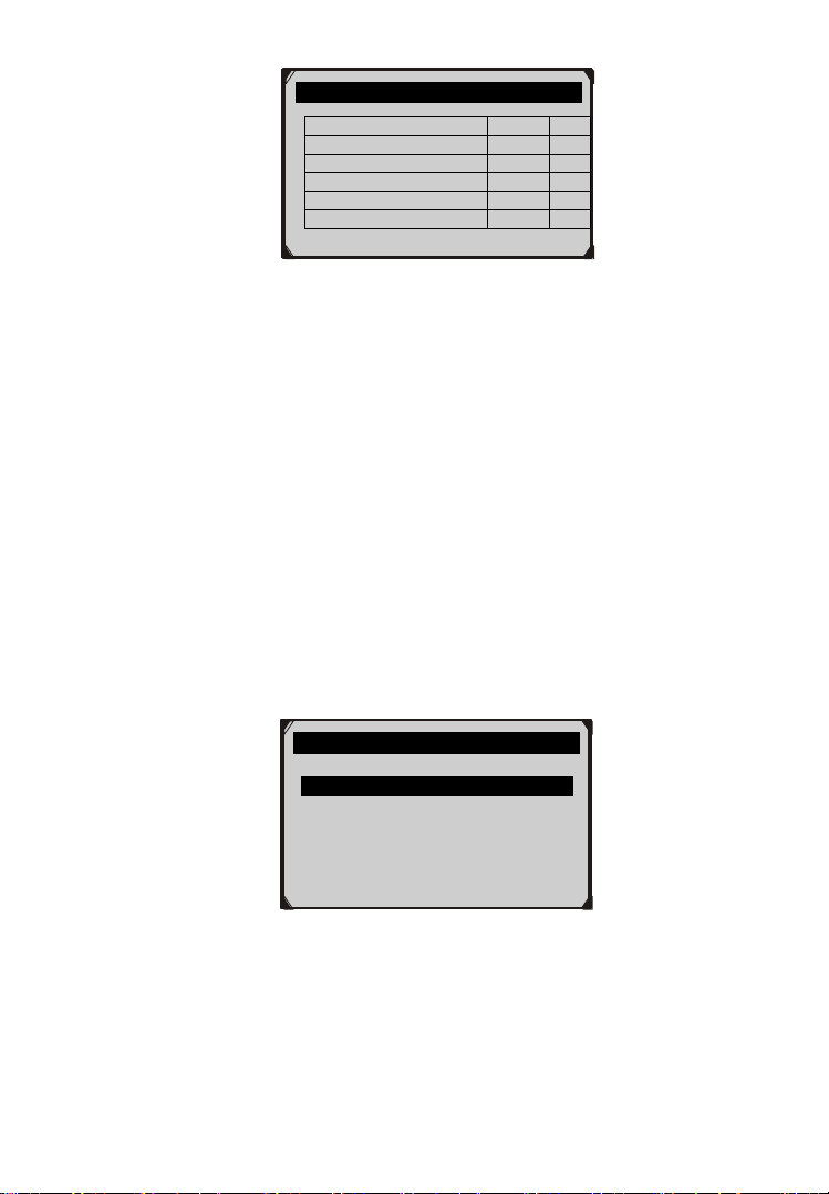
5.2.3 Vehicle Information
Vehicle Information function allows you to view vehicle-specific
information for Specifications, System Type and other Identification.
Figure 5.19
Vehicle Specification
Vehicle: Mustang
Engine Type: Other
Capacity: 3.8L
Transmission: Manual
Fuel Type: Gasoline
Emission Level: Federal Emission
VIN:1FAFP40462F100819
PrefSuf:2R3APB VersionID:4612
OK
System Menu
1. ABS-Anti-Lock Brake/ Traction
Control Module
2. ACM-Audio Control Module
3. BEM-Body Electronic Module
4. FDIM-Front Display Interface
Module
5. HIM-HAVC Integrated Module
6. IPC-Instrument Panel Control
26
5.2.4 Save and Retrieve Files
Save and Retrieve Files function will save the detected vehicle
information. You can directly get the vehicle information next time.
Please follow the instructions above to finish the Auto Scan process
(Figure 5.15), and press the Function button corresponding to Save,
and name the record on the Save Vehicle Record screen.
Figure 5.20
To enter the diagnostic functions through the vehicle record option in
future, please follow these steps:
Select Vehicle Data Recorder from the DAS menu.
Figure 5.21
Click on the vehicle file you desired to enter the diagnostic menu
directly.
Save Vehicle Record
Input vehicle name:
Maximum length is 25 characters..
Finish Show Esc
DAS
1. Start New Session
2. Manual Vehicle Entry
3. Vehicle selection
4. Vehicle Data Recorder
27
Figure 5.22
5.3 Diagnostic Operation
This function allows you to read and clear diagnostic trouble codes
(DTCs), read and save live data. (Take Ford as an example)
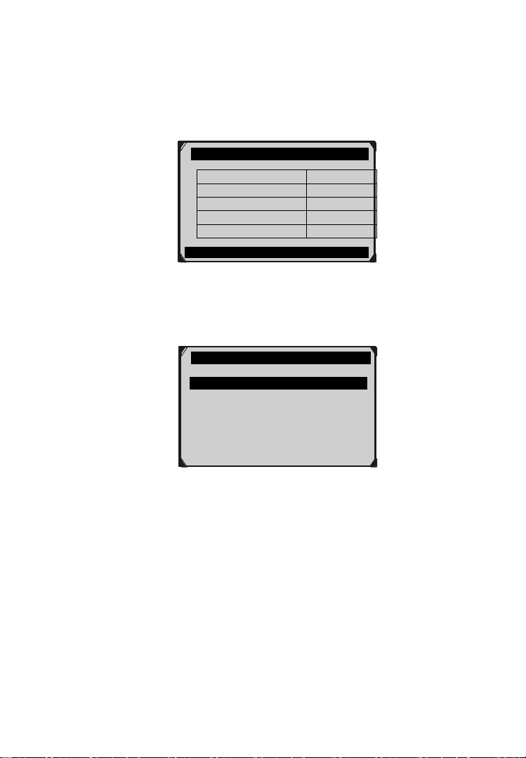
5.3.1 Read Codes
The Read Codes procedure varies for each vehicle being tested. This
section includes the following Read Codes procedures.
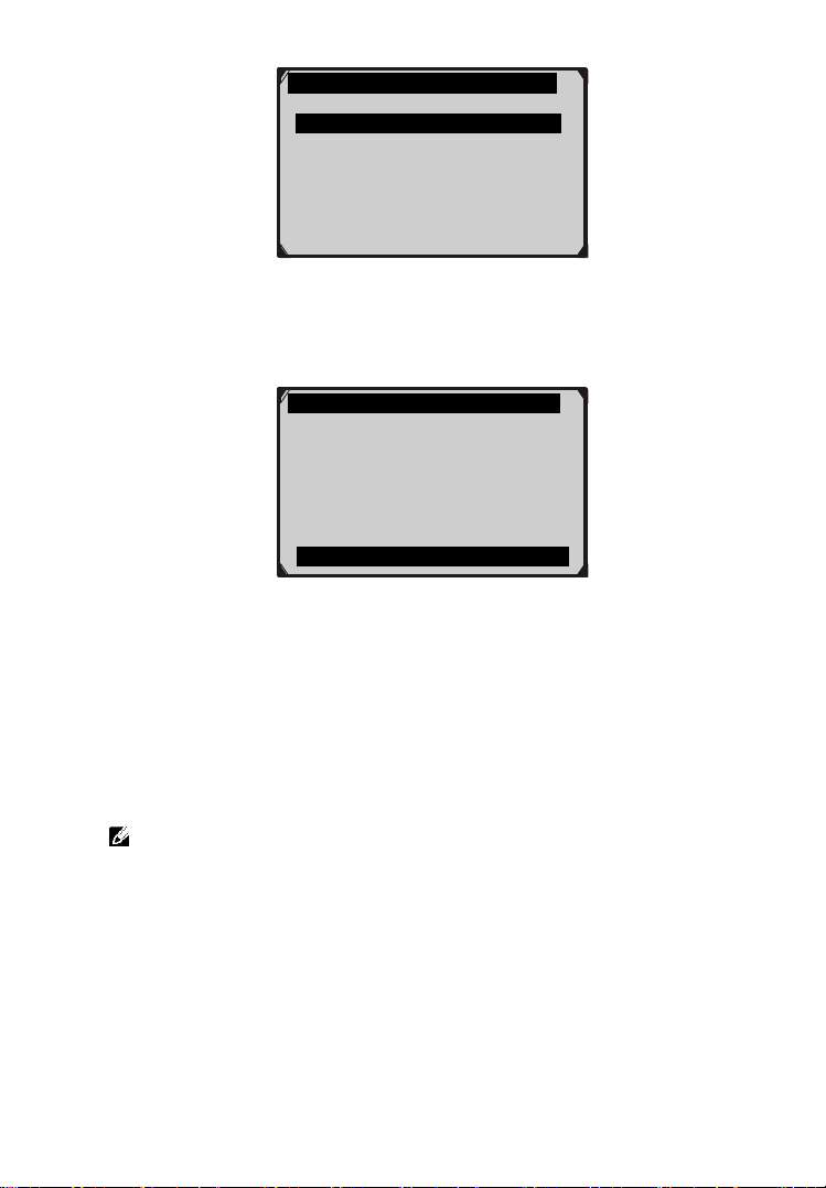
In the Function Menu screen (Figure 5.23), select Read Codes. This
will display the Read Codes menu screen (Figure 5.24).
Figure 5.23
Figure 5.24
Vehicle Data Record
1. Ford1
2. Ford2
Function Menu
1. Read Codes
2. Erase Codes
3. Live Data
Read Codes
1. KOEO On Demand Self-test
2. KOER On Demand Self-test
3. Retrieve CMDTCs(Continuous
Memory Diagnostic Trouble
Codes)

28
In the Read Codes menu, select one of the options to proceed. The
screen will show as below.
Figure 5.25
Select one of the DTC options to view detailed diagnostic trouble
code information.
Figure 5.26
You can save the code results for later review by selecting Save
option on the bottom. When you finished viewing the DTCs, press the
ESC button to return to previous screen.
5.3.2 Erase Codes
After reading and / or reviewing the diagnostic trouble codes, take the
following steps to erase codes from the vehicle. If Erase Codes is not
an available menu option, consult the manufacturer’s service manual
for the correct “clear code” method.
NOTE: This Erase Codes function clears the DTCs from the
selected ECU or provides instructions for how to manually clear
the codes from the ECU.
NOTE: Before performing this procedure, make sure the vehicle’s
ignition key is in the On (Run) position with the engine off.
Select options
1. CMDTCs
2. Freeze Frame-MODE2
3. Pending.
CMDTCs
P0046
Battery voltage high
Status-60(No additional fault
symptom available for this DTC).
P0098
Intake air temperature sensor 2
Circuit high input
Save

29
To Erase DTCs, please follow these steps:
1. With the Function Menu screen displayed (Figure 5.23), click
on Erase Codes. The scan tool displays an instruction message.
2. Follow the instructions on each screen that appears until the
procedure is complete.
3. When finished, press any key to exit.
4. Use Read Codes function to check the codes again to see if DTCs
have been erased successfully. If any codes remain, it indicates
that the vehicle needs maintenance. Please repeat the Erase
Codes steps after repairing the vehicle.
5.3.3 Live Data
Live Data function enables you to view the real-time live data,
including the information of values (volts, rpm, temperature, speed
etc.) and system status information (open loop, closed loop, fuel
system, etc.) generated by vehicle sensors, switches and actuators.
NOTE: If the vehicle must be driven in order to perform a
troubleshooting procedure, ALWAYS have a second person help
you. One person should drive the vehicle while the other person
observes the Scan Tool data. It is dangerous to drive and operate
the Scan Tool at the same time because a serious traffic accident
might be caused.
1) To view live data, use the UP/DOWN scroll button to select Live
Data from Function Menu screen (Figure 5.27), and press the
OK button. The screen will show as below.
Figure 5.27
………… ..Live Data
MFF_RPM(Engine RPM)
1
□ MFF_SOAk(Engine Off Soak Time
Prior to Misfire)
VEHICLE SPEED SENSOR
2
Select All Select Clear All
30
The number to the right of selected item indicates sequence of
this item.
If you want to select the item, press Select button.
To select all the items on the screen, press Select All button. To
clear all the selected items on the screen, press Clear All button.
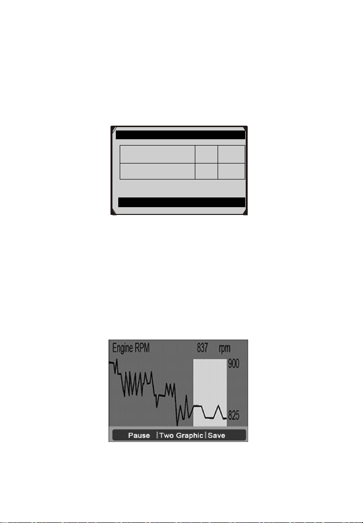
2) Press the OK button to view the information.
Figure 5.28
The three keyboard function buttons work as below.
[One Graphic]: To view the live data waveform.
[Save]: Save the live data.
[Pause]: Suspend viewing and stop saving live data.
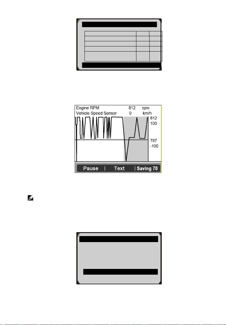
3) Press the FUNCTION button corresponding to One Graphic.
The screen will show the live data waveform as Figure 5.29.
Figure 5.29
Live Data
MFF_RPM(Engine RPM)
837
RPM
VEHICLE SPEED
SENSOR
0
km/h
Pause ︱ one Graphic︱ Save
31
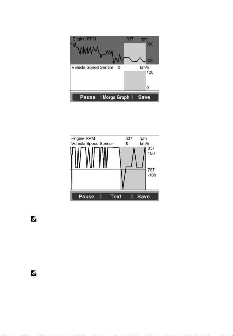
4) Press the FUNCTION button corresponding to Two Graphic,
the screen will show two graphs as Figure 5.30.
Figure 5.30
5) Press the FUNCTION button corresponding to Merge Graph,
the above two graphs will merge together as Figure 5.31.
Figure 5.31
NOTE: Merge Graph can be used to compare two related
parameters in graphic mode. It is especially convenient that you
could select two interacted parameter to merge and see their
relationship.
6) Select Text to return to the view the live data in text form
7) Select Save to record retrieved live data and graphs.
NOTE: The scan tool can only playback text data even though
the data is saved in graphic mode. Since what you are viewing is
“real time” Live Data, the data changes as the vehicle’s
operating conditions change.

32
When there is not enough memory space, a warning message
prompting to delete previously recorded data.
Figure 5.32
If you wish to delete the data, select OK and then go to
Playback screen to delete the data.
Select Pause to suspend recording. You could resume the
recording process again by selecting Continue.
You may review the saved data in Playback function.
Press ESC button to exit.
Save Failed
Memory full, please clean up.
OK

33
6. OBD II Diagnostics
The OBD II Diagnostics function is a fast-access option that allows
you to carry out a quick test on the engine system of OBD II vehicles.
When more than one vehicle control module is detected by the
scan tool, you will be prompted to select the module where the data
may be retrieved. The most often to be selected are the Power-
train Control Module [PCM] and Transmission Control Module
[TCM].
CAUTION: Don’t connect or disconnect any test equipment with
ignition on or engine running.
1) Turn the ignition off.
2) Locate the vehicle’s 16-pin Data Link Connector (DLC).
3) Plug the scan tool cable connector into the vehicle’s DLC and
wait for power on.
4) Turn the ignition on. Engine can be off or running.
5) Select OBDII from the Main Screen on the scan tool (Figure
3.1).
6) Press the OK button to wait for the Menu to appear. A sequence
of messages displaying the OBDII protocols will be observed on
the display until the vehicle protocol is detected.
If the scan tool fails to communicate with the vehicle’s ECU
(Engine Control Unit) more than three times, a “LINKING
ERROR!” message shows up on the display.
Verify that the ignition is ON.
Check if the scan tool’s OBD II connector is securely
connected to the vehicle’s DLC.
Verify that the vehicle is OBD2 compliant.
Turn the ignition off and wait for about 10 seconds. Turn the
ignition back to on and repeat the procedure from step 5.
If the “LINKING ERROR” message does not go away, then
there might be problems for the scan tool to communicate with
34
the vehicle. Contact your local distributor or the
manufacturer’s customer service department for assistance.
7) View a summary of system status (MIL status, DTC counts,
Monitor status) on screen (Figure 6.1). Press ESC button for
Diagnostic Menu (Figure 6.3) to come up.
Figure 6.1
If more than one module is detected, you will be prompted to
select a module before testing (Figure 6.2).
Figure 6.2
Use the UP/DOWN scroll button to select a module and press
the OK button.
6.1 Read Codes
Reading Codes can be done with the key on engine off (KOEO)
or with the key on engine running (KOER).
Stored Codes are also known as “hard codes”, which are fault
codes, or trouble codes that have been stored in the vehicle
computer memory because the faults have reoccurred for more
than a specified amount of key-cycles. These codes will cause
Control Module
Module $10
Module $A4
System Status
MIL Status
OFF
Codes Found
0
Monitors N/A
8
Monitors OK
2
Monitors INC
0
Save OK

35
the control module to illuminate the malfunction indicator light
(MIL) when emission-related fault occurs.
Pending Codes are also referred to as “maturing codes” or
“continuous monitor codes”. They indicate problems that the
control module has detected during the current or last driving
cycle but are not considered serious yet. Pending Codes will not
turn on the malfunction indicator lamp (MIL). If the fault does
not occur within a certain number of warm-up cycles, the code
clears from memory.
Permanent Codes are DTCs that are "confirmed" and are
retained in the non-volatile memory of the computer until the
appropriate monitor for each DTC has determined that the
malfunction is no longer present and is not commanding the
MIL on. Permanent DTC shall be stored in non-volatile
memory and may not be erased by any diagnostic services or by
disconnecting power to ECU.
1) Use UP/DOWN scroll button to select Read Codes from
Diagnostic Menu and press the OK button (Figure 6.3).
Figure 6.3
2) Use the UP/DOWN scroll button to select Stored Codes,
Pending Codes or Permanent Codes from the Read Codes
menu and press the OK button (Figure 6.4).
Diagnostic Menu
1. System Status
2. Read Codes
3. Erase Codes
4. Live Data
5. Freeze Frame
6. I/M Readiness
7. O2 Monitor Test
8. On-Board Monitor Test
36
Figure 6.4
If there is not any Diagnostic Trouble Code, the display indicates
“No (pending) codes are stored in the module!” Wait a few
seconds or press any key to return to the previous screen.
NOTE: Permanent Codes function is available for merely
vehicles supporting the CAN protocols.
1) View DTCs and their definitions on screen.
2) If more than one DTC is found, use the UP/DOWN scroll button
to check all the codes.
If retrieved DTCs contain any manufacturer specific or enhanced
codes, a “Manufacturer specific codes are found! Press any key
to select vehicle make!” message comes up prompting you to
select vehicle manufacturer to view DTC definitions. Use
UP/DOWN scroll button to select manufacturer and then press
OK button to confirm.
Figure 6.5
If the manufacturer of your vehicle is not listed, use the
UP/DOWN scroll button to select Other and press the OK
button.
Read Codes
1. Stored Codes
2. Pending Codes
3. Permanent Codes
Vehicle Manufacturer
BUICK
BMW
CADILLAC
CHEVROLET
CHRYSLER
FORD

37
6.2 Erase Codes
CAUTION: Erasing the Diagnostic Trouble Codes may allow the
scan tool to delete not only the codes from the vehicle’s on-board
computer, but also “Freeze Frame” data and manufacturer specific
enhanced data. Further, the I/M Readiness Monitor Status for all
vehicle monitors is reset to Not Ready or Not Complete status. Do
not erase the codes before the system has been checked completely
by a technician.
NOTE: Erasing codes does not mean that trouble codes in ECU
have been eliminated completely. As long as there is fault with
the vehicle, the trouble codes keeps on presenting.
This function is performed with key on engine off (KOEO). Do
not start the engine.
1) Use the UP/DOWN scroll buttons to select Erase Codes from
Diagnostics Menu and press the OK button (Figure 5.3).
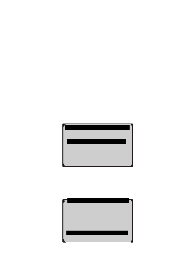
2) After you have pressed OK button, a message will come up
asking you to check the ignition and engine status (Figure 6.6).
Figure 6.6
If you do not want to proceed with erasing codes, press ESC
button or select NO to exit and return to the previous screen.
If you press Yes function button or OK button, a warning
message will come up asking your confirmation (Figure 6.7).
Erase Codes
Ignition on and engine stopped?
Yes No .

38
Figure 6.7
3) Press the OK button to confirm.
If the codes are cleared successfully, an “Erase Done!”
confirmation message shows on the display (Figure 6.8).
Figure 6.8
If the codes are not cleared, then an “Erase Failure. Turn Key
on with Engine off!” message appears (Figure 6.9).
Figure 6.9
4) Press any button to return to Diagnostic Menu.
Erase Codes
Erase Failure.
Turn Key on with
Engine Off!
Press any key to continue
Erase Codes
Erase Done!
Press any key to continue .
Erase Codes
DTCs and Freeze Data will be lost
Do you wish to continue?
Yes No .

39
6.3 Live Data
In this function, you can not only read the live data but also record
data for later review.
View Data
The View Data function allows viewing of live or real time PID
data of vehicle’s computer module(s).
1) To view live data, use the UP/DOWN scroll button to select Live
Data from Diagnostic Menu and press the OK button (Figure
6.3).
2) Wait a few seconds while the scan tool validates the PID MAP
(Figure 6.10).
Figure 6.10
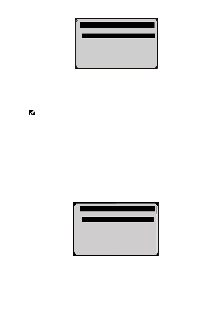
A. View Complete List
1) To view complete set of data, use UP/DOWN scroll button to
select Complete List from Live Data menu and press the OK
button (Figure 6.11).
Figure 6.11
Live Data
Reading PID.01
- Please Wait -
…………………Live Data .
1. Complete List
2. Custom List
40
2) View live PIDs on the screen. Use the UP/DOWN scroll button
for more PIDs if additional information is available on more than
one page ( Figure 6.12).
Figure 6.12
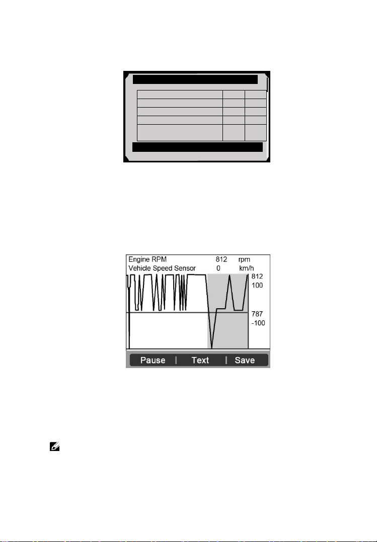
If the “Graphics” on the bottom appears when a PID is
highlighted, graphic information is available. Select
Graphics to view graph (Figure 6.13). PID name, current
value, maximum and minimum values are displayed on the
screen.
Figure 6.13
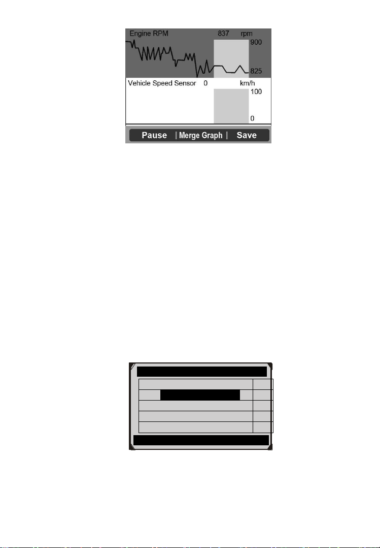
If the “Merge Graph” on the bottom appears when a PID is
selected to view, merged graph information is available
(Figure 6.14).
NOTE: Merge Graph can be used to compare two related
parameters in graphic mode, which is especially convenient in
the Custom List option where you could select two interacted
parameter to merge and see their relationship.
Complete List
Numbers of DTCs
0
Fuel system 1 status
OL
Fuel system 2 status
--
Calculated load value
0.0
%
Engine coolant
temperature
-40
0
C
Pause Graphics Save
41
Figure 6.14
Select Text to return to text viewing of PID data.
Select Save to record retrieved live data and PID graphs.
Select Pause to suspend viewing. You could resume the
viewing process again by selecting Start.
3) Press the ESC button to return to previous menu.
B. View Custom List
1) To view customized PID data, use the UP/DOWN scroll button
to select Custom List from Live Data menu and press the OK
button (Figure 6.11).
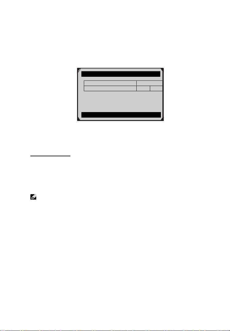
2) Use the UP/DOWN scroll button to move up and down to the
desired items and click Select button to confirm. The selected
parameters are marked with solid squares (Figure 6.15).
Figure 6.15
The number to the right of selected item indicates sequence
of this item.
………… ..Custom List
Numbers of DTCs
1
Fuel system 1 status
2
Fuel system 2 status
Calculated load value
Engine coolant temp
Select All Clear Clear all
42
If you want to deselect the item, press Clear button.
To select all the items on the screen, press Select All button.
To clear all the selected items on the screen, press Clear All
button.
3) Press the OK button to view selected PIDs on screen.
Figure 6.16
4) Press the OK button to view selected PIDs on screen.
Record Data
The Record Data function allows recording vehicle modules’
Parameter Identification (PID) data to help diagnose intermittent
vehicle problems. You could save data files to the SD card and
then use the Playback function to view the saved files.
NOTE: The length of time for each frame varies per vehicle.
Generally, one frame of data is about 1/4 second, or 4 frames per
second.
1) To record live data, with the live data screen displaying, select
Save on the bottom. The scan tool will start timing to record
retrieved live data and PID graphs.
If you record live data under text mode, following screen
shows::
Custom List
Numbers of DTCs
0
Fuel system 1 status
OL
Pause Graphics Save
43
Figure 6.17
If you record live data under graph mode, following screen
shows:
Figure 6.18
NOTE: The scan tool can only playback text data even though the
data is saved in graphic mode.
2) When there is not enough memory space, a warning message
prompting to delete previously recorded data.
Figure 6.19
Save Failed
Memory full, please clean up.
OK
Complete List
Numbers of DTCs
0
Fuel system 1 status
OL
Fuel system 2 status
--
Calculated load value
0.0
%
Engine coolant
temperature
-40
0
C
Pause Graphics Saving 94
44
If you wish to delete the data, select OK and then go
to Playback screen to delete the data.
3) Select Pause to suspend recording. You could resume the
recording process again by selecting Start.
4) You may review the saved data in Playback function.
5) Press ESC button to exit.
6.4 Freeze Frame
Freeze Frame Data allows the technician to view the vehicle’s
operating parameters at the moment a DTC (Diagnostic Trouble
Code) is detected. For example, the parameters may include
engine speed (RPM), engine coolant temperature (ECT), or
vehicle speed sensor (VSS) etc. This information will aid the
technician by allowing the parameters to be duplicated for
diagnostic and repair purposes.
1) To view freeze frame data, use the UP/DOWN scroll button to
select Freeze Frame from Diagnostic Menu and press the OK
button (Figure 6.3).
2) Wait a few seconds while the scan tool validates the PID MAP.
3) If retrieved information covers more than one screen, use the
DOWN scroll button, as necessary, until all the data have shown
up (Figure 6.20).
Figure 6.20
If there is no available freeze frame data, an advisory
message “No freeze frame data stored!” shows on the
display.
Freeze Frame
DTC that caused required
freeze frame data storage
P0193
Fuel system 1 status
OL
Fuel system 2 status
--
Calculated load value
0.0
%
Engine coolant
temperature
-40
0
C
Save

45
4) Select Save to record freeze frame. A confirming message “Save
success!” shows on the display and scan tool return to previous
menu.
5) If you don’t want to save the freeze frame data, press ESC button
to return to previous screen.
6.5 Retrieve I/M Readiness Status
I/M Readiness function is used to check the operations of the
Emission System on OBD II compliant vehicles. It is an excellent
function to use prior to having a vehicle inspected for compliance
to a state emissions program.
CAUTION - By clearing trouble codes you also clear the readiness
status for the individual emission system readiness tests. In order to
reset these monitors, the vehicle must be driven through a complete
drive cycle with no trouble codes in memory. Times for reset vary
depending on vehicle.
Some latest vehicle models may support two types of I/M Readiness
tests:
A. Since DTCs Cleared - indicates status of monitors since the
DTCs are erased.
B. This Drive Cycle - indicates status of monitors since the
beginning of the current drive cycle.
An I/M Readiness Status result of “NO” does not necessarily
indicate that the vehicle being tested will fail the state I/M
inspection. For some states, one or more such monitors may be
allowed to be “Not Ready” to pass the emission inspection.
“OK” -- Indicates that a particular monitor being checked has
completed its diagnostic testing.
“INC” -- Indicates that a particular monitor being checked has
not completed its diagnostic testing.
“N/A” -- The monitor is not supported on that vehicle.
1) Use the UP/DOWN scroll button to select I/M Readiness from
Diagnostic Menu and press OK button (Figure 6.3).

46
2) Wait a few seconds while the scan tool validates the PID MAP.
3) If the vehicle supports both types of tests, then both types will be
shown on the screen for selection (Figure 6.21).
Figure 6.21
4) Use the UP/DOWN scroll button, as necessary, to view the status
of the MIL light (“ON” or “OFF) and the following monitors:
For spark ignition engines:
MIS -- Misfire Monitor
FUEL -- Fuel System Monitor
CCM -- Comprehensive Component Monitor
EGR – EGR System Monitor
O2S -- O2 Sensors Monitor
CAT -- Catalyst Monitor
EVAP -- Evaporative System Monitor
HTR -- O2 Sensor Heater Monitor
AIR -- Secondary Air Monitor
HCAT -- Heated Catalyst Monitor
For compression ignition engines:
MIS -- Misfire Monitor
FUEL -- Fuel System Monitor
CCM -- Comprehensive Component Monitor
EGR – EGR System Monitor
HCCAT -- NMHC Catalyst Monitor
…………… I/M Readiness .
1. Since DTCs Cleared
2. This Drive Cycle
47
NCAT -- NOx Aftertreatment Monitor
BP -- Boost Pressure System Monitor
EGS -- Exhaust Gas Sensor Monitor
PM -- PM Filter Monitor
Figure 6.22
5) If the vehicle supports readiness test of “This Drive Cycle”, a
screen of the following displays: (Figure 6.23)
Figure 6.23
6) Use the UP/DOWN scroll button for more PIDs if additional
information is available on more than one page. Or use the
LEFT/RIGHT scroll button to view PIDs in the previous/next
page.
7) Press the ESC button to return to Diagnostic Menu.
6.6 O2 Monitor Test
OBD2 regulations set by SAE require that relevant vehicles
monitor and tests on the oxygen (O2) sensors to identify problems
related to fuel efficiency and vehicle emissions. These tests are not
Since DTCs cleared
MIL Status
OFF
Misfire Monitoring
N/A
Fuel system monitoring
OK
Comprehensive
component monitoring
OK
Catalyst monitoring
N/A
Heated catalyst monitor
N/A
This Drive Cycle
MIL Status
OFF
Misfire Monitoring
N/A
Fuel system monitoring
OK
Comprehensive
component monitoring
OK
Catalyst monitoring
N/A
Heated catalyst monitor
N/A
48
on-demand tests and they are done automatically when engine
operating conditions are within specified limits. These test results
are saved in the on-board computer's memory.
The O2 Monitor Test function allows retrieval and viewing of O2
sensor monitor test results for the most recently performed tests
from the vehicle's on-board computer.
The O2 Monitor Test function is not supported by vehicles which
communicate using a controller area network (CAN). For O2
Monitor Test results of CAN-equipped vehicles, see chapter “On-
Board Mon. Test”.
1) Use the UP/DOWN scroll button to select O2 Monitor Test from
Diagnostic Menu and press OK button (Figure 6.3).
2) Wait a few seconds while the scan tool validates the PID MAP.
3) Use the UP/DOWN scroll button to select O2 sensor from O2
Monitor Test menu and press OK button (Figure 6.24).
Figure 6.24
If the vehicle does not support the mode, an advisory message
will be displayed on the screen (Figure 6.25).
.......... ..O2 Monitor Test …
1.O2 Bank1 Sensor1
2.O2 Bank1 Sensor2
3.O2 Bank2 Sensor1
4.O2 Bank2 Sensor2
…………….O2 Monitor Test…………..
The selected mode is
not supported!
Press any key to continue .

49
Figure 6.25
4) View test results of selected O2 sensor (Figure 6.26).
Figure 6.26
5) Use the UP/DOWN scroll button to view more screens of data if
additional information is available in more than one page.
6) Press the ESC button to return to the previous menu.
6.7 On-Board Monitor Test
The On-Board Monitor Test is useful after servicing or after
erasing a vehicle’s control module memory. The On-Board
Monitor Test for non-CAN-equipped vehicles retrieves and
displays test results for emission-related power train components
and systems that are not continuously monitored. The On-Board
Monitor Test for CAN-equipped vehicles retrieves and displays
test results for emission-related power train components and
systems that are and are not continuously monitored. Test and
components IDs are determined by the vehicle manufacturer.
In this test, there are typically a minimum value, a maximum value,
and a current value for each monitor. By comparing the current value
with the minimum and maximum value, the scan tool will determine
if it is OK.
1) Use the UP/DOWN scroll button to select On-Board Monitor
Test from Diagnostic Menu and press the OK button (Figure 6.3).
2) Wait a few seconds while the scan tool validates the PID MAP.
… ……… .O2 Bank1 Sensor2 .
Rich-Lean Threshd V
Lean-Rich Threshd V
Low for Switch (V)
High for Switch (V)
Rich-Lean Threshd S
Lean-Rich Threshd S
50
3) The scan tool will prompt you to select the vehicle make (If you
have selected the vehicle before, the Vehicle Manufacturer
screen would not appear again).
Figure 6.27
4) After you select the vehicle manufacturer, the scan tool shows the
On-Board Monitors tests for specific monitoring systems.
5) From On-Board Monitor Test menu, use the UP/DOWN scroll
button to select a test to view and press the OK button (Figure
6.28).
Figure 6.28
If the vehicle under test does not support the mode, an advisory
message will be displayed on the screen (Figure 6.29).
On-Board Monitor Test
1. Test $01 Data
2. Test $03 Data
3. Test $10 Data
4. Test $21 Data
5. Test $22 Data
6. Test $25 Data
Vehicle Manufacturer
BUICK
BMW
CADILLAC
CHRYSLER
FORD
GM
51
Figure 6.29
For CAN-equipped vehicles, test selections can be as below:
Figure 6.30
6) Use the UP/DOWN scroll button to select the desired monitor
from On-Board Monitor Test menu and press the OK button.
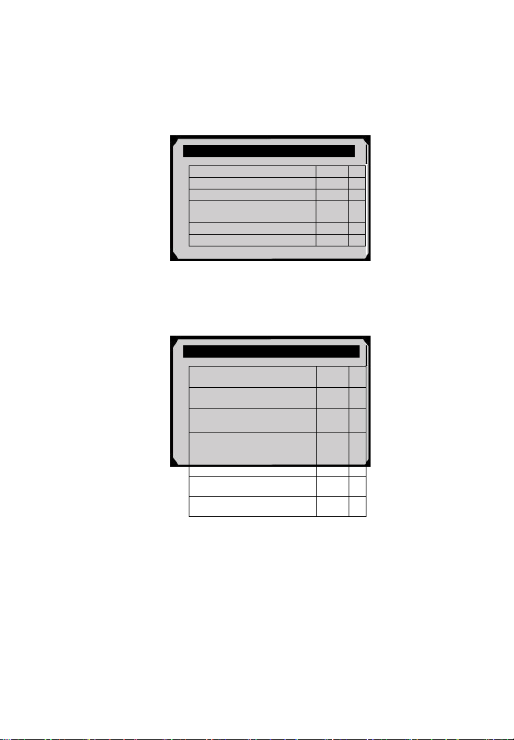
7) View test data on screen.
Figure 6.31
For CAN-equipped vehicles, test results displayed can be as
below:
On-Board Monitor Test
The selected mode is
not supported
Press any key to continue
On-Board Monitor Test ..
1. EGR Monitor
2. Mis-Fire Monitor Data
3. Mis-Fire Cylinder 1 Data
4. Mis-Fire Cylinder 2 Data
5. Mis-Fire Cylinder 3 Data
6. Mis-Fire Cylinder 4 Data
Test $01 Data
ID
11
Module
$10
Test Value
0400
Min Limit
0200
Max Limit
----
Status
OK
52
Figure 6.32
8) Press ESC button to return to the previous menus.
6.8 Component Test
The Component Test function allows initiating a leak test for the
vehicle's EVAP system. The scan tool itself does not perform the
leak test, but commands the vehicle's on-board computer to start
the test. Different vehicle manufacturers might have different
criteria and methods for stopping the test once it has been started.
Before starting the Component Test, refer to the vehicle service
manual for instructions to stop the test.
1) Use the UP/DOWN scroll button to select Component Test from
Diagnostic Menu and press the OK button (Figure 6.3).
2) Wait for the scan tool to display the Component Test menu.
Figure 6.33
3) If the test has been initiated by the vehicle, a confirmation
message will be displayed on the screen.
Component Test
1.EVAP Sys. Leak Test
Flow Test
ID
11
Module
$10
Test Value
0.10
%
Min Limit
0.00
%
Max Limit
95.0
%
Status
OK

53
Figure 6.34
Some vehicles do not allow scan tools to control vehicle
systems or components. If the vehicle under test does not
support the EVAP Leak Test, an advisory message is
displayed on the screen.
Figure 6.35
4) Wait a few seconds or press any key to return to previous screen.
6.9 View Vehicle Information
The Vehicle Info. function enables retrieval of Vehicle
Identification No. (VIN), Calibration ID Nos. (CINs), Calibration
Verification Nos. (CVNs) and In-use Performance Tracking on
2000 and newer vehicles that support Mode 9.
1) Use UP/DOWN scroll button to select Vehicle Info. from the
Diagnostic Menu and press OK button (Figure 6.3).
2) An advisory message comes up to remind you. Wait a few
seconds or press any key to continue.
Component Test
Command Sent!
Press any key to continue
.............Component Test
The selected mode is
not supported
Press any key to continue
54
Figure 6.36
3) Wait for the scan tool to display the Vehicle Info. menu.
Figure 6.37
If the vehicle does not support this mode, a message shows on
the display warning that the mode is not supported.
4) From Vehicle Info. menu, use the UP/DOWN scroll button to
select an available item to view and press the OK button.
5) View retrieved vehicle information on screen.
Figure 6.38
6) Press the ESC button to return previous menu.
Vehicle ID Number
VIN
1FAFP40462F100819
Esc
Vehicle Info.
Turn key on
with engine off!
Press any key to continue
Vehicle Info.
1. Vehicle ID Number
2. Calibration ID
3. Cal. Verf. Number
55
6.10 Modules Present
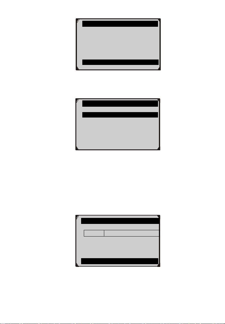
The Modules Present function allows viewing of the module IDs
and communication protocols for OBD2 modules in the vehicle.
1) Use the UP/DOWN scroll button to select Modules Present from
Diagnostic Menu and press OK button (Figure 6.3).
2) View modules present with their IDs and communication
protocols.
Figure 6.39
3) Select Save to save the modules data and return to previous menu.
Or press ESC button to exit.
6.11 DTC Lookup
The DTC Lookup function allows user to search definitions of
DTC stored in built-in DTC library.
1) Use the UP/DOWN scroll button to select DTC Lookup from
Diagnostic Menu and press OK button (Figure 6.3).
2) Wait for the scan tool to display the DTC Lookup screen.
Figure 6.40
Modules Present
Protocol
ID
SAE J1850 PWM
$10
Save
DTC Lookup
Only PCBU can be the first letter
to be put in. Only 0~9,a~f for the
rest letters...
Finish Show Esc
56
3) Select Show and a soft keyboard will pop up. Use LEFT/RIGHT
button and UP/DOWN button to move to the desired character,
then press OK button to confirm.
4) After you input the DTC code, select Finish and the scan tool will
display this code’s definition on screen.
Figure 6.41
5) Press Yes or OK button to proceed. The scan tool will display
DTC definition as below.
Figure 6.42
Use the LEFT/RIGHT scroll button to view the previous / next
DTC.
Select Save to record code definition.
For manufacturer specific codes, you need to select a vehicle
make on an additional screen to look for DTC definitions.
If definition could not be found (SAE or Manufacturer Specific),
the scan tool displays “Please refer to vehicle service manual!”
6) Press No or ESC button to return to previous menu.
Trouble Codes
P0005
Fuel Shutoff Valve A Control
Circuit/Open
Save
Input Dialog Box
P0005
Do you want to save and
continue?
Yes No

57
7. Oil Reset
7.1 General Information
The Engine Oil Life System calculates when to change the engine
oil and filter based on vehicle use. An oil change is required
whenever indicated by the display and according to the
recommended maintenance schedule. Whenever the oil is changed,
reset the system so it can calculate when the next oil change is
required. If a situation occurs where the oil is changed prior to a
service indicator being turned on, also reset the system.
IMPORTANT: Always reset the engine oil life to 100% after
every oil change.
NOTE: All required work must be carried out before the service
indicators are reset. Failure to do so may result in incorrect
service values and cause DTCs to be stored by the relevant
control module.
NOTE: For some vehicles, the scan tool can perform added
functionality to reset additional service lights (maintenance cycle,
service interval). Take BMW as an example, its service reset
function includes engine oil, spark plugs, front/rear brakes,
coolant, particle filter, brake fluid, microfilter, vehicle inspection,
exhaust emission inspection and vehicle check.
All software screens shown in this manual are examples, actual test
screens may vary for each vehicle being tested. Observe the menu
titles and onscreen instructions to make correct option selections.
7.2 Reset Operation
1. Turn the ignition on but do not start the engine.
2. Turn on the scan tool and wait for the Main Screen to appear.
3. Select Oil Reset icon in the Main Screen (Figure 3.1) and wait
for the vehicle manufacturer screen. Choose the correct vehicle
make.
There are two ways to perform the reset service.
58
A. Manual Reset
Almost all Asian vehicles and most American and European vehicles
can be reset manually by technicians.
NOTE: In this manner, the scan tool will not communicate
with the vehicle being tested.
To finish this procedure, please follow these steps (Take Ford as an
example):
1) From the vehicle make screen, select Ford and press OK button.
Figure 7.1
2) Step by step, select the right options for your vehicle according
to each screen that appears.
Figure 7.2
Model
1. Ford
2. Lincoln
3. Mercury
59
Figure 7.3
3) After entering the vehicle information, the scan tool displays
manual reset message as below.
Figure 7.4
4) Follow the instructions to reset the service manually.
5) Press ESC button to exit.
B. Auto Reset
Most American and European vehicles can be reset automatically by
the scan tool.
NOTE: In this manner, the scan tool will communicate with
the vehicle being tested. If there is a linking error, please refer
to 3.8 product troubleshooting.
To finish this procedure, please follow these steps (Take PEUGEOT
as an example):
1) From the vehicle make screen, select Peugeot and press OK
button.
Year
1.2005
2.2003-2004
3.1998-2002
Information
1.Select Press Reset At Oil Change
from the setup control for the
current display mode.
2.Press Reset Control to reset
Oil change.
OK
60
Figure 7.5
2) Step by step, select the right options for your vehicle according
to each screen that appears.
Figure 7.6
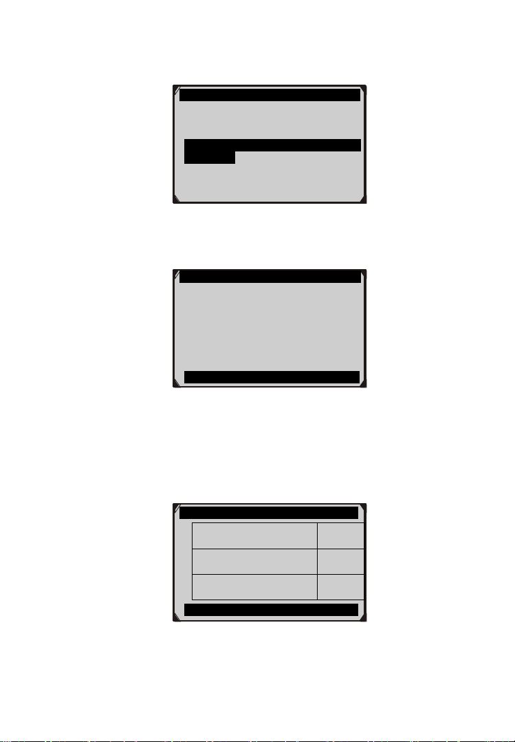
3) After you have entered the vehicle information, the oil reset
screen will display as below.
Figure 7.7
4) The Instrument Panel option enables you to finish oil reset
service in one step by resetting the ECU to default values
automatically. The procedures work as below.
System
1.Instrument panel
2.BSI
PEUGEOT
1.206/206MUX
2.206+
3.207
4.307
5.308
6.406

61
In the Oil Reset menu, select Service Zero Reset function
and press OK button.
Figure 7.8
The tool will automatically begin resetting the vehicle ECU
to default values.
Figure 7.9
When the resetting is finished, the tool will display a
confirmation message.
Figure 7.10
5) The BSI option enables you to finish oil reset service
automatically and manually. The procedures work as below.
Oil Reset
1.Service Zero Reset
Service Zero Reset
Check the resetting of
the maintenance to zero.
Cancel
Service Zero Reset
Operation Completed.
Press any key to continue
62
In the Oil Reset menu, select Resetting to zero of the
service mileage function and press OK button.
Figure 7.11
The tool will reset the oil service to zero automatically.
Figure 7.12
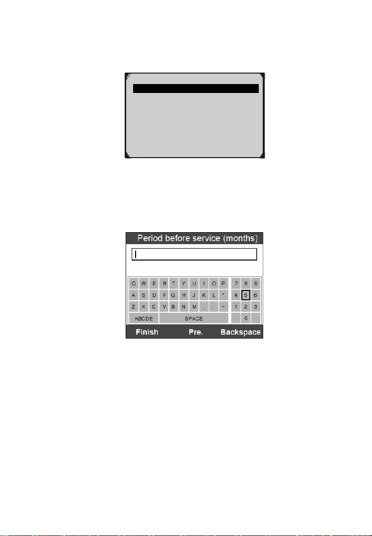
In the Oil Reset menu (Figure 7.11), select Maintenance
function and press OK button. The screen will display the
preset maintenance information of the vehicle. The
information items vary with different vehicles.
Figure 7.13
Oil Reset
1. Read Codes
2. Erase Codes
3. Resetting to zero of the service
mileage
4.Maintenance
Resetting to zero
Maintenance mileage zero
reset carried out.
Press any key to continue
Maintenance
Period before service
(months)
6
First maintenance
threshold
china
Maintenance
limit(km)
7400
Finish Edit ESC
63
For the First maintenance threshold, you have two choices.
Select the correct option and press OK button to save the
change.
Figure 7.14
For the Period before service or Maintenance limit, press
Edit key on the bottom to pop up a soft keyboard to facilitate
your input.
Figure 7.15
The three keyboard function keys work as below.
Finish --- When you finished the input, select this key to
confirm your input and exit.
Pre. --- Moves a space to the left.
Backspace --- Uses this key to erase the previous digit or
character when typing.
1.China
2.Another country
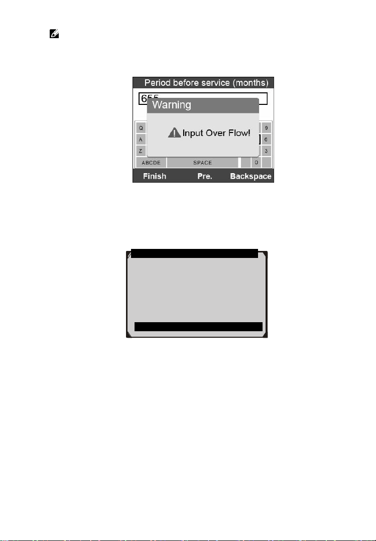
64
NOTE: The data you input must be in the reasonable range,
which is defined by the preset values in ECU. If you enter a data
out of range, the tool will display a warning message.
Figure 7.16
When you have finished your configuration, select Finish key
on the bottom of the screen, then the tool will begin the oil
reset service.
Figure 7.17
Maintenance
Configuration carried out.
Press any key to continue

65
8. EPB
This electric parking brake (EPB) function has a multitude of uses to
maintain the electronic braking systems safely and effectively. The
applications include deactivating/activating the brake control system,
assisting with brake fluid control, brake diagnostics, opening and
closing brake pads, setting brakes after disc or pad replacement and
also reading and clearing EPB/SBC trouble codes. It is also capable
of retrieving Fault Codes information from the ECU.
8.1 EPB Safety
It may be dangerous to perform electric parking brake (EPB) system
maintenance, so before you begin the service work, please keep these
rules in mind.
Ensure that you are fully familiar with the braking system and its
operation before commencing any work.
The EPB control system may be required to be deactivated before
carrying out any maintenance/diagnostic work on the brake
system. This can be done from the tool menu.
Only carry out maintenance work when the vehicle is stationary
and on level ground.
Ensure that the EPB control system is reactivated after the
maintenance work has been completed.
NOTE: Autel accepts no responsibility for any accident or injury
arising from the maintenance of the Electric Parking Brake
system.
8.2 EPB Maintenance
1) Turn the ignition off.
2) Release the park brake and make sure the car is properly blocked.
3) Connect the tool to vehicle and wait for the tool power on.
4) Turn the ignition on.
66
5) Select EPB icon in the Main Screen (Figure 3.1) and wait for
the vehicle manufacturer screen. Choose the correct vehicle
make. (Take PEUGEOT as an example)
Figure 8.1
6) After you have selected the vehicle make, the electric parking
brake system screen will display as below.
Figure 8.2
7) In the electric parking brake system screen, use the UP/DOWN
button to select EPB to enter EPB system. In the EPB diagnostic
function, the tool can read codes, erase codes, record live data,
read ECU information, perform active test, and perform special
function. For the functions already being described before,
please refer to chapter 5. OBDII Diagnostics for details.
System
1. EPB
2. ABS
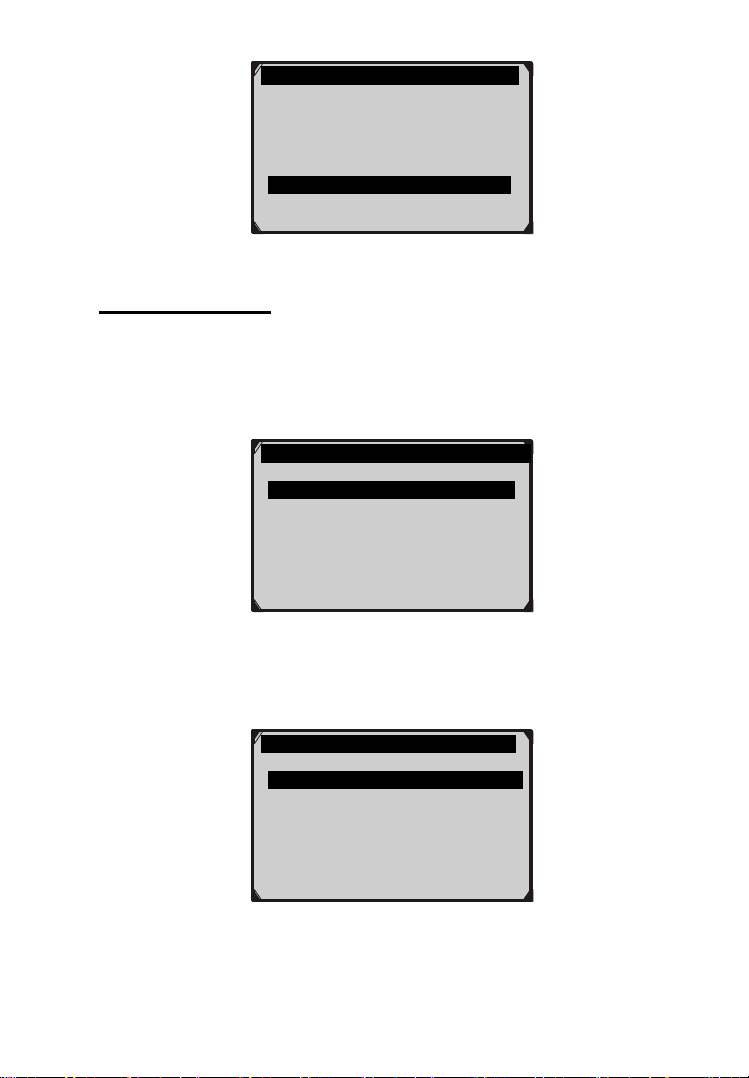
67
Figure 8.3
Special Function
1) In the Diagnostic Menu (Figure 8.3), use the UP/DOWN button
to select Special Function to do the EPB test, which includes
Brake cable replacement and Electric parking brake
replacement.
Figure 8.4
2) In the EPB screen, use the UP/DOWN button to select Brake
cable replacement. The screen shows as below.
Figure 8.5
Diag. Menu
1. Read Codes
2. Erase Codes
3. Live Data
4. Active Test
5. ECU Information
6. Special Function
Replacement parts
1.Brake cable replacement
2. Electric parking brake
replacement.
Brake cable replacement
1.Put in fitting/removal position
2.Cable tensioning
3.Electric parking brake
calibration.

68
In the Brake cable replacement screen, the tool can perform
three functions.
A. Put in fitting or removal position
This function enables you to fit in or remove the brake cable safely
and easily. It will take a few seconds to execute this command.
Figure 8.6
When the job is done successfully, the tool will display a message
to confirm.
Figure 8.7
If the job fails to finish, the tool will display a message to remind
user of a problem. After you exit the diagnosis program, please
repair the problem immediately.
Put in fitting/removal position
Activation in progress!
Stop
Put in fitting/removal position
Positioning done.
To replace or remove the brake
cables, refer to the mechanical
“Remove-refit” procedure
Press any key to continue
OK

69
Figure 8.8
B. Cable tensioning
Once the brake cable is fit in, you would use this function to adjust
its tension. It will take a few seconds to execute this command.
Figure 8.9
When the job is done successfully, the tool will display a message
to confirm.
Figure 8.10
If the job fails to finish, the tool will display a message to remind
user of a problem. After you exit the diagnosis program, please
repair the problem immediately.
Put in fitting/removal position
Activation done, a problem
occurred during the operation.
Press any key to continue
OK
Cable tensioning
Cable tensioning done.
Now calibrate the Electric parking
brake (See “Brake cable
replacement” menu)
Press any key to continue
OK
Cable tensioning
Activation in progress!
OK

70
Figure 8.11
C. Electric parking brake calibration
When both functions above have completed successfully, you still
need to calibrate the electric parking brake system.
This function is to check if the EPB is working correctly, which
should be performed after work has been completed on the EPB
or vehicle braking system. It will remove any air gap from the
brake pads and check the EPB pressure.
After you select this function, the tool will automatically work in
the following procedure.
Figure 8.12
Figure 8.13
Electric parking brake calibration
Activation in progress!
OK
Electric parking brake calibration
Please wait! The tool should stop
and restart the communication
with the Electric parking brake
ECU.
Cable tensioning
Activation done, a problem
occurred during the operation.
Press any key to continue
OK

71
When the job is done successfully, the tool will display a message
to confirm.
Figure 8.14
If the job fails to finish, the tool will display a message to remind
user of a problem. After you exit the diagnosis program, please
repair the problem immediately.
Figure 8.15
3) In the EPB screen, use the UP/DOWN button to select
Electric parking brake replacement. The screen shows as
below.
Figure 8.16
Electric parking brake calibration
Electric parking brake cable
calibration done!
Restart Back
Electric parking brake calibration
Activation done, a problem
occurred during the control.
Restart Back
OK
Electric parking brake replacement
1. Put in fitting/removal position
2. Cable tensioning
3. Electric parking brake calibration
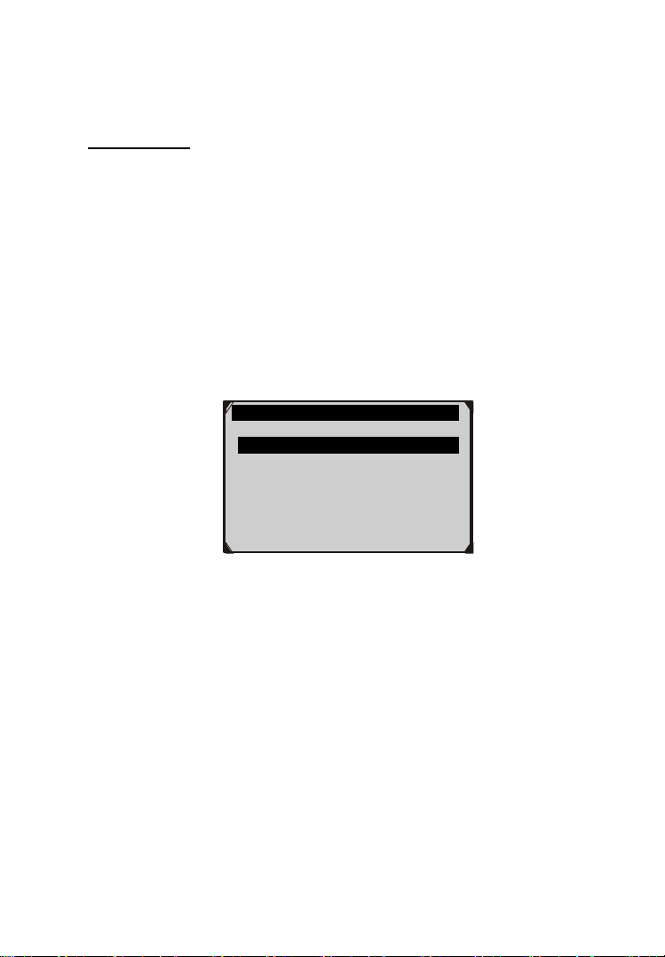
72
In the Electric parking brake replacement screen, the tool can also
perform three functions, which details could refer to the same
functions described in the Brake cable replacement menu above.
Active Test
During an active test, the tool is used for outputting commands to the
ECU in order to drive the actuators. This test determines the integrity
of the system or parts by monitoring the operation of the actuators or
by reading the EPB ECU data.
To carry out an active test, please follow these steps.
1. Follow the instructions above to display the Diag. menu
screen.(Figure 8.3)
2. Select Active Test and a list of possible tests appear. The test
items in the list vary with different vehicles.
Figure 8.17
3. Select a test and the tool will display an information screen as
“The 'apply electric parking brake' operation is used to test
the operation of the brake cables statically. If you start the
actuator test, you must wait for the component to stop
operating before starting another actuator test. Press 'OK' to
apply the electric parking brake or press 'Cancel' to go back
to the list of possible operation.” Select OK to continue or
Cancel to exit.
4. The tool may display information during and after the test. The
information varies by vehicle.
Active
1.Apply electric parking brake
2.Release electric parking brake

73
Figure 8.18
5. When the test is finished, there may be three results displaying
on the screen.
The test is finished successfully.
The test is stopped by the user.
The test did not finish.
In the first condition, the tool will display an information screen as
“The operation was performed correctly. Put the vehicle on a
vehicle lift and check that the rear wheels are locked. Check that
the 'Electric parking brake on' message is display on the control
panel and that the LED illuminates on the control panel.”
In the second condition, the tool will display an information screen as
“Operation of the actuator test was stopped by the user. Press
‘Cancel' to go back to the list of possible operations.”
In the third condition, the tool will display an information screen as
“The actuator test did not finish operating. Please perform the
following check: Read the faults to resolve any possible faults
relating to the electric motor or to the cables.”
IMPORTANT: Make sure that the components to be tested are
not physically damaged and are well assembled.
WARNING: Please stop repairing the components to be tested
before the test starts and keep a certain distance during the test.
8.3 ABS Maintenance
Apply electric parking brake
Listen to the noise of the
electric motor!
OK
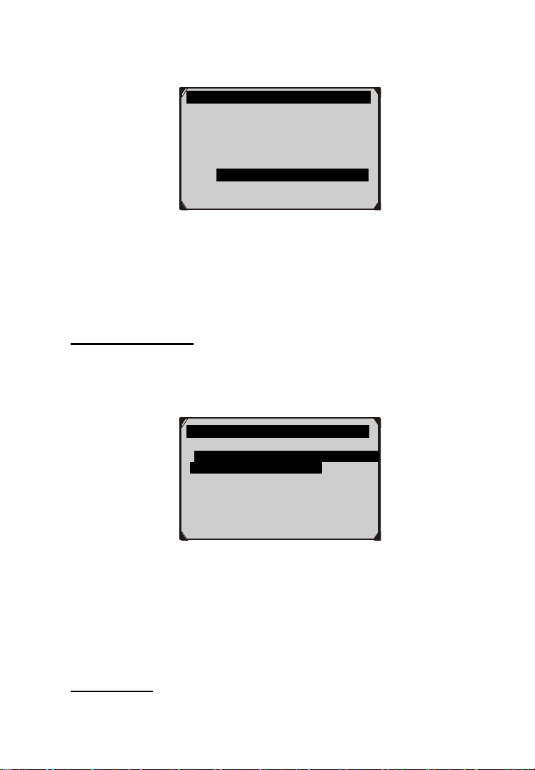
74
In the System menu (Figure 8.2), use UP/DOWN button to select
ABS to do ABS maintenance. The scan tool displays as below:
Figure 8.19
In the ABS diagnostic function, the tool can read codes, erase codes,
record live data, read ECU information, perform active test, and
perform special function. For the functions already being described
before, please refer to chapter 5. OBDII Diagnostics for details.
Special Function
1) In the Diagnostic Menu (Figure 8.19), use the UP/DOWN
button to select Special Function to do the ABS test. The scan
tool displays as below.
Figure 8.20
2) In the EPB menu, select the desired function and press OK
button. If the operation is finished successfully, the scan tool will
display a confirmation message. Otherwise, it will display a
message to remind user of a problem. After you exit the
diagnosis program, please repair the problem immediately.
Active Test
Diag. Menu
1. Read Codes
2. Erase Codes
3. Live Data
4. Active Test
5. ECU Information
6. Special Function
ABS
1. Reactivation of automatic application
of the electric parking brake
2. Deactivation of automatic application
of the electric parking brake function

75
1) In the Diagnostic Menu (Figure 8.19), use the UP/DOWN
button to select Active Test to do the 8.test. The scan tool
displays as below.
Figure 8.21
2) In the Active menu, use the UP/DOWN button to select the
desired actuator to begin test. If the selected actuator works
correctly, the tool will display a confirmation message as below
(Figure 8.22). Otherwise, it will display a message to remind
user of a problem. After you exit the diagnosis program, please
repair the problem immediately.
Figure 8.22
Active
1. ABS/ASR recirculation pump
2. Left front intake solenoid valve
3. Right front intake solenoid valve
4. Left rear intake solenoid valve
5. Right rear intake solenoid valve
6. Switching solenoid valve 1
7. Switching solenoid valve 2
Active
Operation completed!
No fault detected!
Press any key to continue
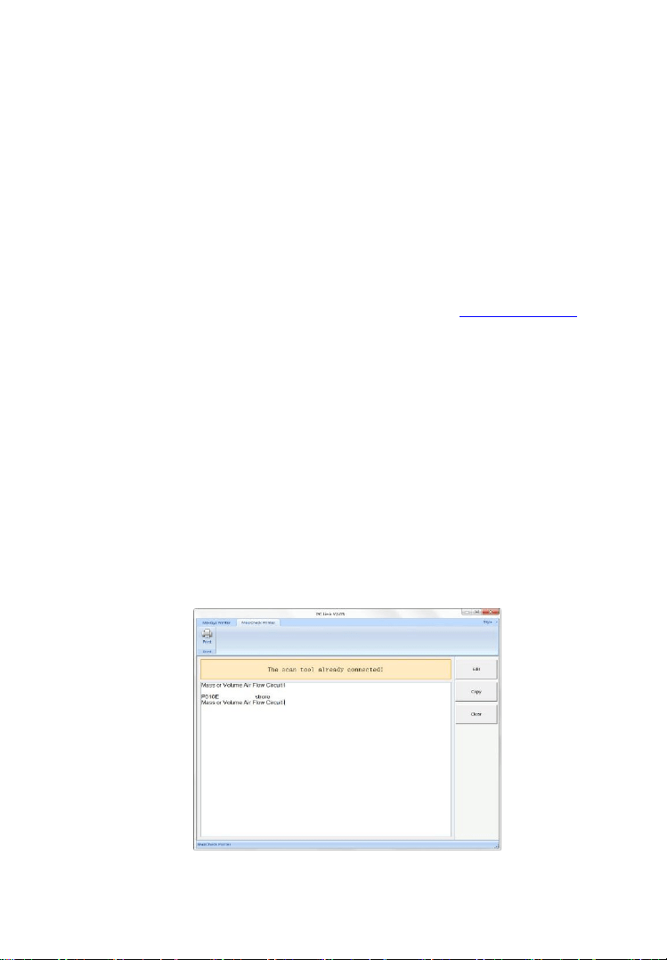
76
9. Print Data
The Print Data function allows printing out diagnostic data
recorded by the scan tool or customized test reports by connecting
the scan tool to a PC or laptop with the USB cable supplied.
To print out retrieved data, you need the following tools:
DiagLink Main Unit
A PC or laptop with USB ports
A USB cable
1) Download Maxi PC Suite from our website www.autel.com and
install it on the computer.
2) Connect the scan tool to computer with the USB cable supplied.
3) Run PC Link software on computer.
4) Select Playback function in Main Screen of the scan tool. In
Review data screen, use the UP/DOWN scroll button to select
the files you want to print. Wait for the reviewing window to
display (Figure 4.2), and then select Print function on the bottom.
The selected file will be uploaded to your computer. For more
detailed instructions, please refer to 4. Playback Data.
5) Click MaxiCheck Printer on the navigation bar and the PC Link
window will display as below.
Figure 9.1

77
6) The selected data will display on the textbox of PC Link. By
selecting the function buttons, you could execute the following
operations:
Print – Print all data in the textbox to a printer connected to
your computer.
Edit – Once clicked, the software will automatically open a
NOTEPAD window with all recorded data showing on.
Copy – Copy all data in the textbox to the clipboard.
Clear – Delete all data in the textbox.
NOTE: The scan tool can only print text data even though the
data is saved in graphic mode.

78
10. Software Update
This function allows you to update the scan tool software through
a computer.
NOTE: You can get one free vehicle software for the first time
after registration. Please download the first free software via
Maxi PC Suite before purchasing online otherwise you will lose
access to the free vehicle software.
10.1 Register the Tool
User would update the scan tool ONLY after you had registered the
tool with an effective Autel ID. Then you could download software,
update online, retrieve information and get warranty service.
NOTE: Before registration, please confirm your network is
working properly.
1) Two ways to access the Update mode.
Remove the Micro SD card from the device and connect it
with a computer for updating, or connect your tool with a
computer via the supplied USB cable and select Update on
the Main Screen to enter Update Mode (Figure 10.1).
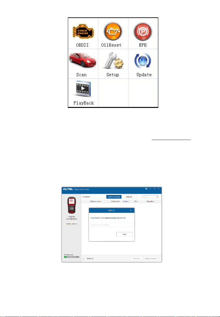
79
Figure 10.1
2) Make sure that your computer is connected to the Internet.
3) Download Maxi PC Suite from our website www.autel.com and
install it on the computer.
4) Run Maxi PC Suite on the computer.
5) The Maxi PC Suite will automatically detect the connected
device’s serial number. If the connected device has not been
registered yet, a Sign Up message displays.
Figure 10.2
6) Enter your email address to register, click Next to continue.
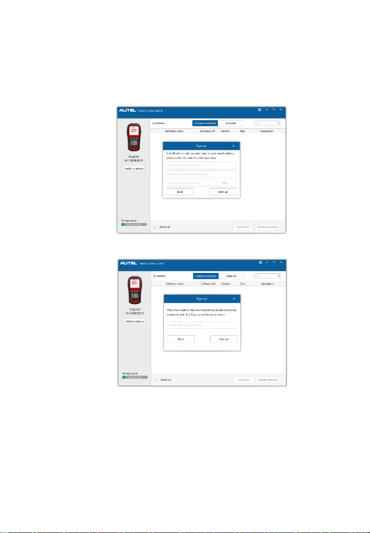
80
7) If you haven’t registered before, a captcha will be sent to your
email address. Input your password and the captcha you received,
and then click Sign up to register the connected device (Figure
10.3). If the connected device has already been registered, the
Maxi PC Suite will turn to the Update menu directly. If you have
registered before, input your password and proceed (Figure 10.4).
Figure 10.3
Figure 10.4
If you are a new member to Autel, you will receive a
verification code in your email box. Enter a password and
the verification code and then click Register button.
If you have already had an Autel ID, register the product
with your email address and password directly.
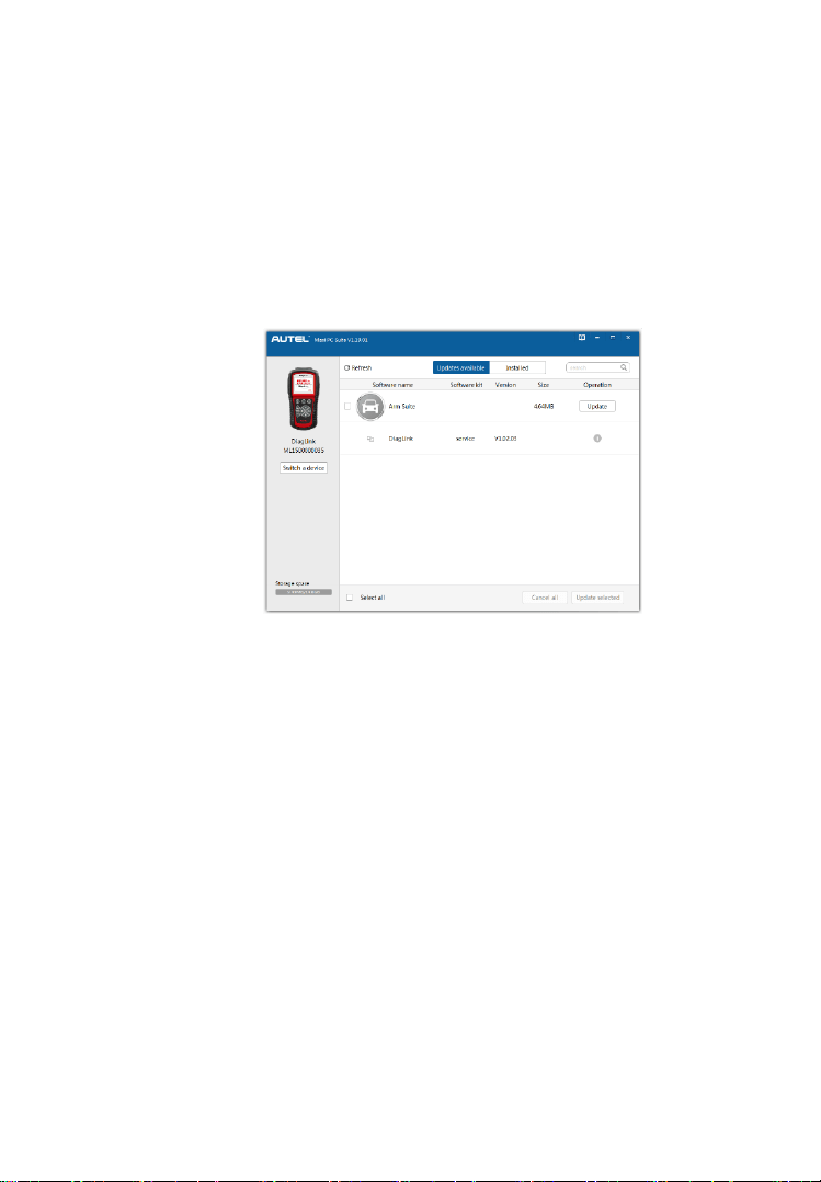
81
10.2 Update Procedure
Autel frequently releases software updates that you can download. The
Update feature makes it very easy to determine and get exactly what
you need.
1) You will come into the Update window after successful
registration. First install the management program by click
Update button (Figure 10.5).
Figure 10.5
2) If the device has already been installed with the latest version of
management program, you will directly come to the next step.
3) The program list will be automatically loaded. If you have never
downloaded any software package, the Updates window will
show as below (Figure 10.6).
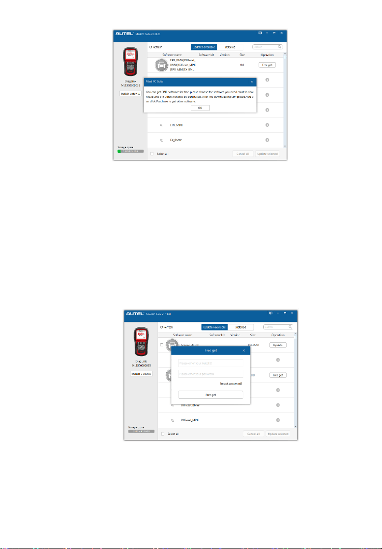
82
Figure 10.6
4) If the program has already installed OBD in the latest version,
OBD software will not show in the list.
5) You can download one vehicle make software for free for the first
time. Find out the desired item to be downloaded and click Free
get button on the same line.
6) In a popped dialog box, enter your Autel ID and your password,
and click Free get (Figure 10.7).
Figure 10.7
7) If your Autel ID is correct and valid, the program will establish
communication with Server on-line and reload the list (Figure
10.8).
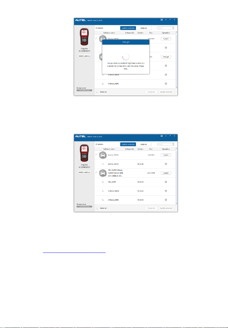
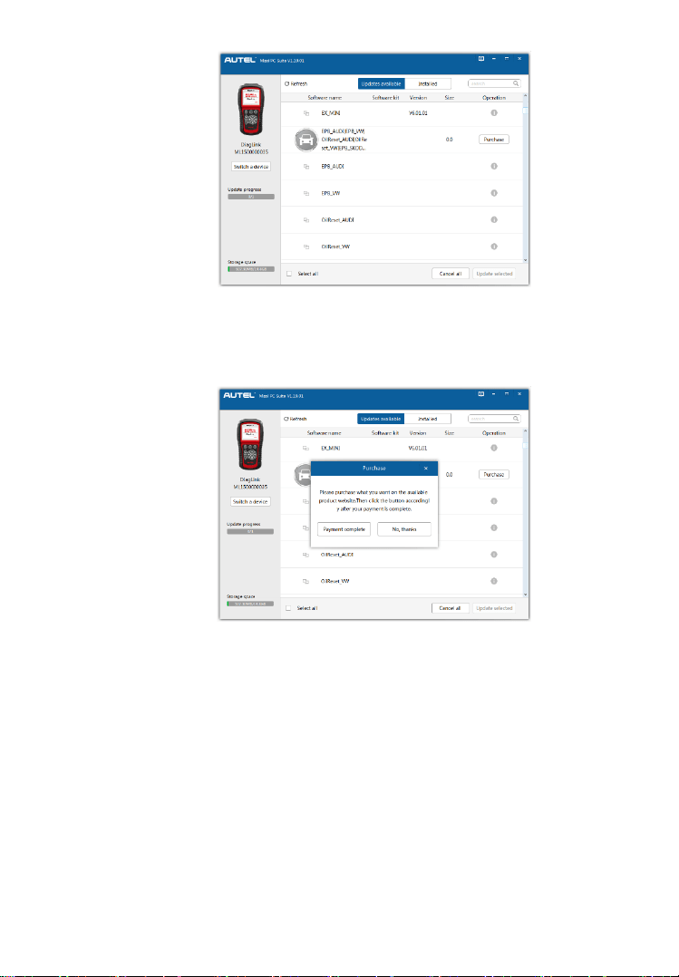
84
Figure 10.10
10) After successful purchase, click Payment Complete button.
Figure 10.11
Batch Update:
Select the items that you would like to update by clicking
on the check boxes next to those items. Then click the
Update Selected button near the bottom-right corner.
Or, click the Select All checkbox near the bottom-left corner
and all updatable items will be selected automatically. Then
click the Update Selected button near the bottom-right
corner.
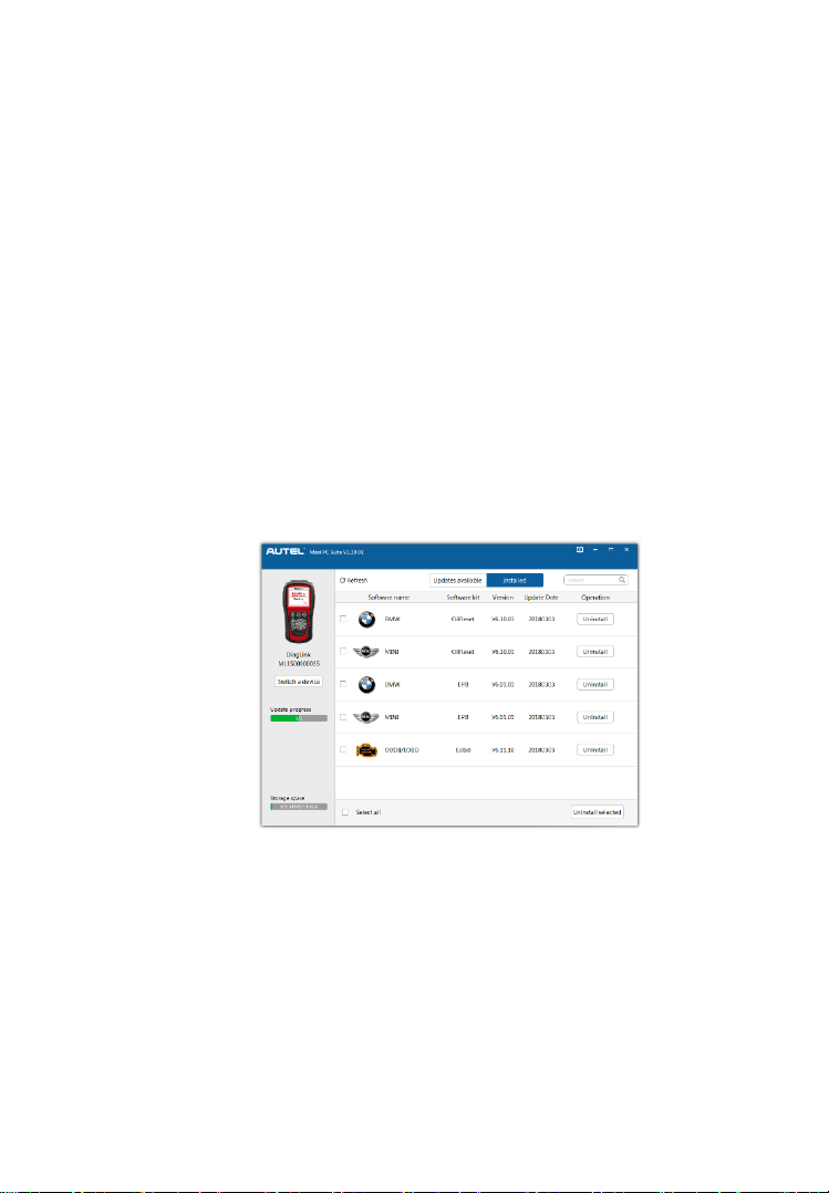
85
When the downloading is completed, the downloaded
programs will be installed automatically. The new version
will replace the old one.
Single update:
Find out the desired item and click the Update button on the
same line.
When the downloading is completed, the downloaded
program will be installed automatically. The new version
will replace the old one.
10.3 View or Delete Programs
To view the list of installed programs or to delete an installed program,
please follow these steps:
Click the Installed tag entry and the page will show the list of
programs installed (Figure 10.12).
Figure 10.12
Select the program(s) that you would delete.
Single delete: Click the Uninstall button on the line of your
would-be-deleted program.
Batch delete: Select the programs that you would delete by
clicking on the check boxes to the left of those items. Then
click the Uninstall Selected button at the bottom-right corner.
Or, click the Select All checkbox near the bottom-left corner
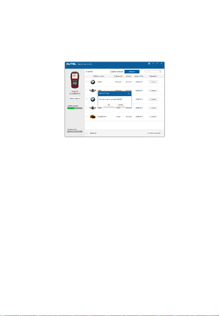
86
and all updatable items will be selected automatically. Then
click the Update Selected button near the bottom-right corner.
A window asking “Are you sure to uninstall XXX?” will pop
up for your confirmation (Figure 10.12).
Figure 10.12
Click OK to delete the program(s) selected, or click Cancel to
cancel the action.
The deleted program will be automatically added to the end of
program list in Updates Available in case you would like to
install it again.
Theoretically, all programs in latest versions will be automatically
compatible with the older versions. However, if your scan tool do have
a compatible problem and want to retrieve the older version for some
programs, you may need to delete them first, and then install the older
version again. Choose older version from the pull-down menu of
program version.

87
11. Warranty and Service
11.1 Limited One Year Warranty
Autel warrants to its customers that this product will be free from all
defects in materials and workmanship for a period of one (1) year from
the date of the original purchase, subject to the following terms and
conditions:
1) The sole responsibility of Autel under the Warranty is limited to
either the repair or, at the option of Autel, replacement of the scan
tool at no charge with Proof of Purchase. The sales receipt may be
used for this purpose.
2) This warranty does not apply to damages caused by improper use,
accident, flood, lightning, or if the product was altered or repaired
by anyone other than the Manufacturer’s Service Center.
3) Autel shall not be liable for any incidental or consequential
damages arising from the use, misuse, or mounting of the scan
tool. Some states do not allow limitations on how long an implied
warranty lasts, so the above limitations may not apply to you.
4) All information in this manual is based on the latest information
available at the time of publication and no warranty can be made
for its accuracy or completeness. Autel reserves the right to make
changes at any time without notice.
11.2 Service Procedures
If you have any questions, please contact your local store, distributor
or visit our website at www.autel.com.
If it becomes necessary to return the scan tool for repair, contact your
local distributor for more information.