Loading ...

2
Leveling screw Leveling screw
Top view
Finished
interior
wall
Front view
Interior adjacent
wall
Leveling screw
2”
16”
Side view
Interior
wall
Finished Àoor
See note
left side
OUTSIDE
Recommend 2” minimum
clearance to interior
adjacent wall both
sides.
Chaseway knockout
3 ”
3” min.,
adjustable
to 5”
2Ǫ”
13¾”
2Ǫ”
min.
42”
2”
Installation Instructions
INSTALL GROUND SCREW
Install from the rear and secure
from the inside of the sub-base
using a nut. Secure branch
circuit (or other) ground wire
using a second nut.
INSTALL MOUNTING CLIP
It is important to select the correct
mounting clip for the type of wall
sleeve being installed.
• Painted Steel: Use Type D
•Molded Polymer: Use Type E
•Snap Together: Use Type F
Molded sleeve (RAB77*)
Mounting clip
for molded
sleeve
Type E
Metal Sleeve (RAB71*)
Mounting
clip for metal
sleeve
Type D
Green ground
screw
Type C
Type A
screws
Type C
screws
Access
Plates
Type C
screws
Type B screws
6”
6”
Type A
screws
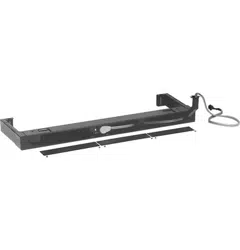
Side channels are
adjustable from 13 ¾”
to 2 ¾” in length by
EUHDNLQJRႇVHFWLRQV
of side channels.
*all versions
NOTE: Remove knockouts from inside out. Knockouts (enclosure) 4 rear, 4 bottom.
Use as required for branch circuit wire entrance.
Loading ...
Loading ...
Loading ...