English
Installation manual
R410A Split series
Français
Español
Manuel dinstallation
Série split R410A
Manual de instalación
Serie Split R410A
INSTALLATION
MANUAL
R410A Split Series
Models
RXS30LVJU
RXS36LVJU
RKS30LVJU
RKS36LVJU
00_CV_3P300674-3.indd 1 10/21/2011 1:32:11 PM
1
■
English
Safety Precautions
•ReadtheseSafetyPrecautionscarefullytoensurecorrectinstallation.
•ThismanualclassiestheprecautionsintoDANGER,WARNINGandCAUTION.
Besuretofollowalltheprecautionsbelow:theyareallimportantforensuringsafety.
DANGER ...... Indicates an imminently hazardous situation which, if not avoided, will result in death or serious
injury.
WARNING .... Failure to follow any of WARNING is likely to result in such grave consequences as death or serious
injury.
CAUTION ..... Failure to follow any of CAUTION may in some cases result in grave consequences.
•Thefollowingsafetysymbolsareusedthroughoutthismanual:
Besuretoobservethisinstruction. Besuretoestablishagroundconnection. Neverattempt.
•Aftercompletinginstallation,testtheunittocheckforinstallationerrors.Givetheuseradequateinstructions
concerningtheuseandcleaningoftheunitaccordingtotheOperationManual.
DANGER
•Refrigerantgasisheavierthanairandreplacesoxygen.Amassiveleakcouldleadtooxygendepletion,especially
inbasements,andanasphyxiationhazardcouldoccurleadingtoseriousinjuryordeath.
•Iftherefrigerantgasleaksduringinstallation,ventilatetheareaimmediately.
Refrigerantgasmayproduceatoxicgasifitcomesincontactwithresuchasfromafanheater,stoveorcookingdevice.
Exposuretothisgascouldcausesevereinjuryordeath.
•Aftercompletingtheinstallationwork,checkthattherefrigerantgasdoesnotleak.
Refrigerantgasmayproduceatoxicgasifitcomesincontactwithresuchasfromafanheater,stoveorcookingdevice.
Exposuretothisgascouldcausesevereinjuryordeath.
•Donotgroundunitstowaterpipes,telephonewiresorlightningrodsbecauseincompletegroundingcouldcausea
severeshockhazardresultinginsevereinjuryordeath,andtogaspipesbecauseagasleakcouldresultinan
explosionwhichcouldleadtosevereinjuryordeath.
•Safelydisposeofthepackingmaterials.
Packingmaterials,suchasnailsandothermetalorwoodenparts,maycausestabsorotherinjuries.
Tearapartandthrowawayplasticpackagingbagssothatchildrenwillnotplaywiththem.
Childrenplayingwithplasticbagsfacethedangerofdeathbysuffocation.
•Donotinstallunitinanareawhereammablematerialsarepresentduetoriskofexplosionresultinginserious
injuryordeath.
•Donotgroundunitstotelephonewiresorlightningrodsbecauselightningstrikescouldcauseasevereshock
hazardresultinginsevereinjuryordeath,andtogaspipesbecauseagasleakcouldresultinanexplosionwhich
couldleadtosevereinjuryordeath.
WARNING
•Installationshallbelefttotheauthorizeddealeroranothertrainedprofessional.
Improperinstallationmaycausewaterleakage,electricalshock,re,orequipmentdamage.
•Installtheairconditioneraccordingtotheinstructionsgiveninthismanual.
Incompleteinstallationmaycausewaterleakage,electricalshock,reorequipmentdamage.
•Besuretousethesuppliedorexactspeciedinstallationparts.
Useofotherpartsmaycausetheunittocometofall,waterleakage,electricalshock,reorequipmentdamage.
•Installtheairconditioneronasolidbasethatislevelandcansupporttheweightoftheunit.
Aninadequatebaseorincompleteinstallationmaycauseinjuryorequipmentdamageintheeventtheunitfallsoffthebaseorcomesloose.
•Electricalworkshallbecarriedoutinaccordancewiththeinstallationmanualandthenational,stateandlocal
electricalwiringcodes.
Insufcientcapacityorincompleteelectricalworkmaycauseelectricalshock,reorequipmentdamage.
•Besuretouseadedicatedpowercircuit.Neveruseapowersupplysharedbyanotherappliance.
Followallappropriateelectricalcodes.
•Forwiring,useawireorcablelongenoughtocovertheentiredistancewithnosplicesifpossible.
Donotuseanextensioncord.Donotputotherloadsonthepowersupply.
Useanonlyaseparatededicatedpowercircuit.
(Failuretodosomaycauseabnormalheat,electricshock,reorequipmentdamage.)
•Usethespeciedtypesofwiresforelectricalconnectionsbetweentheindoorandoutdoorunits.
Followallstateandlocalelectricalcodes.
Firmlyclamptheinter-unitwiresotheirterminalsreceivenoexternalstresses.
Incompleteconnectionsorclampingmaycauseterminaloverheating,reorequipmentdamage.
01_EN_3P300674-3.indd 1 10/13/2011 2:23:50 PM
2
■
English
Safety Precautions
WARNING
•Afterconnectingallwiresbesuretoshapethecablessothattheydonotputunduestressontheelectricalcovers,
panelsorterminals.
Installcoversoverthewires.Incompletecoverinstallationmaycauseterminaloverheating,electricalshock,reorequipmentdamage.
•Wheninstallingorrelocatingthesystem,besuretokeeptherefrigerantcircuitfreefromallsubstancesotherthan
thespeciedrefrigerant(R410A),suchasair.
(Anypresenceofairorotherforeignsubstanceintherefrigerantcircuitcausesanabnormalpressurerisewhichmayresultinrupture,resulting
ininjury.)
•Duringpump-down,stopthecompressorbeforeremovingtherefrigerantpiping.
Ifthecompressorisstillrunningandthestopvalveisopenduringpump-down,airwillbesuckedinwhentherefrigerantpipingisremoved,
causingabnormallyhighpressurewhichcouldleadtoequipmentdamageorandpersonalinjury.
•Duringinstallation,attachtherefrigerantpipingsecurelybeforerunningthecompressor.
Iftherefrigerantpipesarenotattachedandthestopvalveisopenduringpump-down,airwillbesuckedinwhenthecompressorisrun,
causingabnormallyhighpressurewhichcouldleadtoequipmentdamageandpersonalinjury.
•Besuretoinstallagroundfaultcircuitinterrupterbreaker.
Failuretoinstallagroundfaultcircuitinterrupterbreakermayresultinelectricallyshocks,orrepersonalinjury.
CAUTION
•Donotinstalltheairconditionerwheregasleakagewouldbeexposedtoopenames.
Ifthegasleaksandbuildsuparoundtheunit,itmaycatchre.
•Establishdrainpipingaccordingtotheinstructionsofthismanual.
Inadequatepipingmaycausewaterdamage.
•Tightenthearenutaccordingtothespeciedtorque.Atorquewrenchshouldbeused.
Ifthearenutistightenedtoomuch,thearenutmaycrackovertimeandcauserefrigerantleakage.
•Donottouchtheheatexchangerns.
Improperhandlingmayresultininjury.
•Beverycarefulaboutproducttransportation.
SomeproductsusePPbandsforpackaging.DonotuseanyPPbandsforameansoftransportation.Itisdangerous.
•Makesuretoprovideforadequatemeasuresinordertopreventthattheoutdoorunitbeusedasashelterbysmall
animals.
Smallanimalsmakingcontactwithelectricalpartscancausemalfunctions,smokeorre.Pleaseinstructthecustomertokeeptheareaaround
theunitclean.
•Thetemperatureofrefrigerantcircuitwillbehigh,pleasekeeptheinter-unitwireawayfromcopperpipesthatare
notthermallyinsulated.
•ElectricalworkmustbeperformedinaccordancewiththeNEC/CECbyauthorizedpersonnelonly.
Accessories
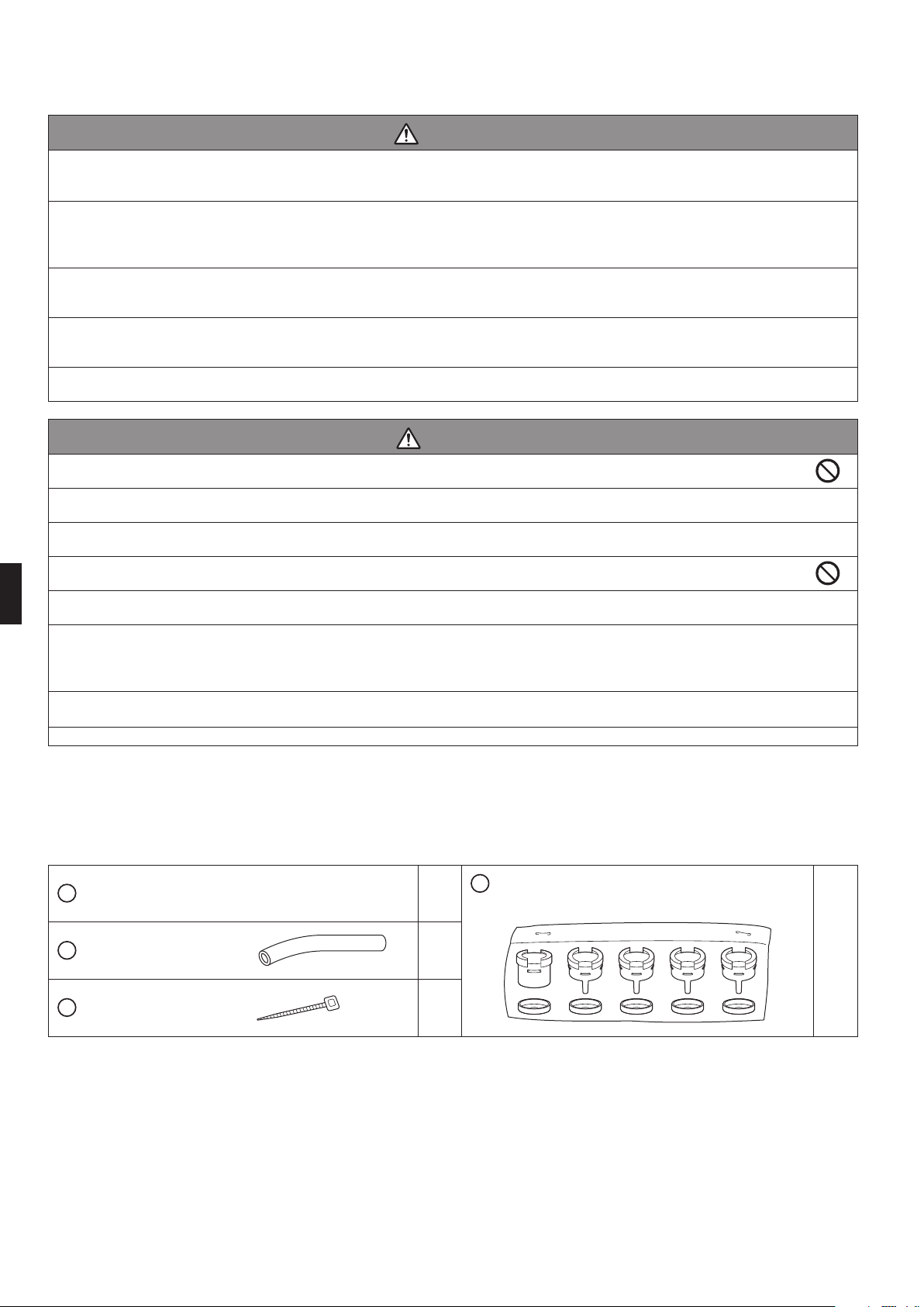
Accessoriessuppliedwiththeoutdoorunit:
Installationmanual 1
Drainsocketassembly
(Onlyheatpumpmodels)
1 Tube 2
Bindingband
2
A
B
C
D
01_EN_3P300674-3.indd 2 10/13/2011 2:23:51 PM
3
■
English
Precautions for Selecting the Location
1) Chooseaplacesolidenoughtobeartheweightandvibrationoftheunit,wheretheoperationsoundswillnotbeamplied.
2)
Choosealocationwherethehotairdischargedfromtheunitortheoperationsoundswillnotdisturbtheneighborsoftheuser.
3)
Avoidinstallingnearbedroomssothatoperationsoundswillnotbeaproblem.
4)
Theremustbesufcientspacesforcarryingtheunitintoandoutofthesite.
5)
Theremustbesufcientspaceforairpassageandnoobstructionsaroundtheairinletandtheairoutlet.
6)
Thesitemustbefreefromthepossibilityofammablegasleakageinanearbyplace.
7)
Installunits,powercordsandinter-unitwireatleast10ft(3m)awayfromtelevisionandradiosets.Thisistopreventinterference
toimagesandsounds.(Noisesmaybeheardeveniftheyaremorethan10ft(3m)awaydependingonradiowaveconditions.)
8)
Incoastalareasorotherplaceswithsaltyatmosphereofsulfategas,corrosionmayshortenthelifeoftheairconditioner.
9)
Sincedrainowsoutoftheoutdoorunit,donotplaceanythingundertheunitwhichmustbekeptawayfrommoisture.
NOTE
Cannotbeinstalledhangingfromceilingorstacked.
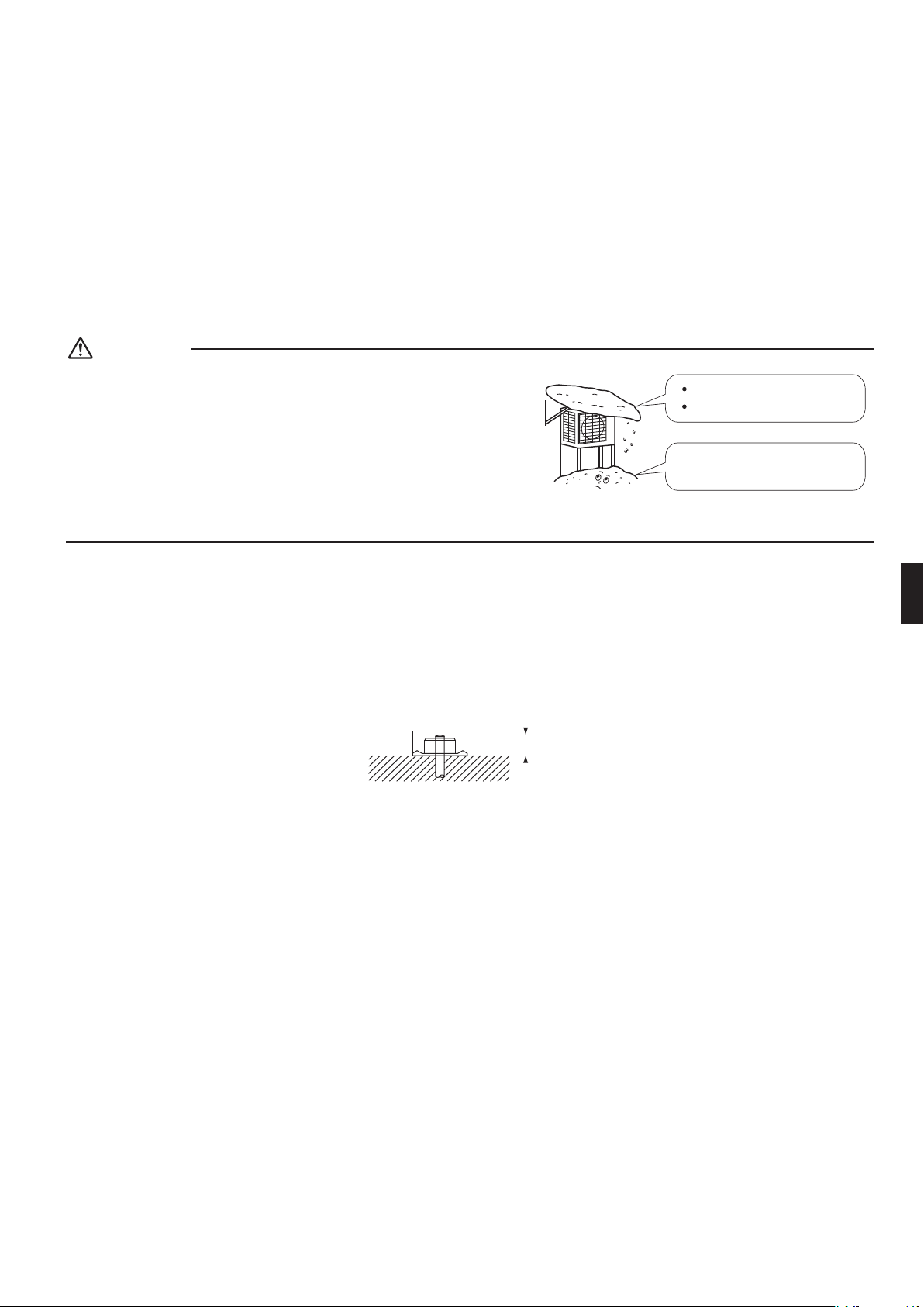
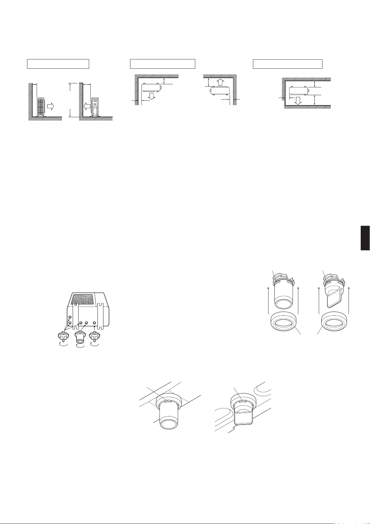
CAUTION
Whenoperatingtheairconditionerinalowoutdoorambient
temperature,besuretofollowtheinstructionsdescribedbelow.
•Topreventexposuretowind,installtheoutdoorunitwithitssuction
sidefacingthewall.
•Neverinstalltheoutdoorunitatasitewherethesuctionsidemay
beexposeddirectlytowind.
•Topreventexposuretowind,itisrecommendedtoinstallabafe
plateontheairdischargesideoftheoutdoorunit.
•Inheavysnowfallareas,selectaninstallationsitewherethesnow
willnotaffecttheunit.
Construct a large canopy.
Construct a pedestal.
Install the unit high enough off the
ground to prevent burying in snow.
Precautions on Installation
•
Checkthestrengthandleveloftheinstallationgroundsothattheunitwillnotcauseanyoperatingvibrationornoiseafterinstalled.
•Inaccordancewiththefoundationdrawing,xtheunitsecurelybymeansofthefoundationbolts.
(Prepare4setsof1/2inch(M12)foundationbolts,nutsandwasherseachwhichareavailableonthemarket.)
•Itisbesttoscrewinthefoundationboltsuntiltheirendsare3/4inch(20mm)fromthefoundationsurface.
3/4 inch
(20mm)
01_EN_3P300674-3.indd 3 10/13/2011 2:23:51 PM
4
■
English
Outdoor Unit Installation Drawings
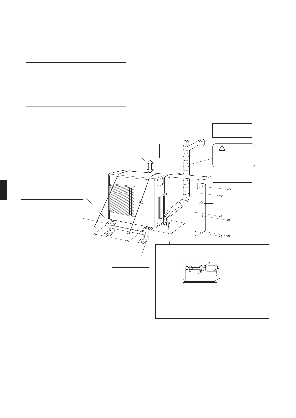
Max. allowable piping height
Min. allowable piping length
Max. allowable piping length 98.4ft (30m)
6.56ft (2m)
65.6ft (20m)
Liquid pipe
Gas pipe
O.D. 3/8 inch (9.5mm)
O.D. 5/8 inch (15.9mm)
0.54oz/ft (50g/m)
Additional refrigerant
required for refrigerant
pipe exceeding
32.8ft (10m) in length.
**
*
*
Be sure to add the proper amount of additional refrigerant.
Failure to do so may result in reduced performance.
**
The suggested shortest pipe length is 6.56ft (2m), in order to avoid
noise from the outdoor unit and vibration.
(Mechanical noise and vibration may occur depending on how
the unit is installed and the environment in which it is used.)
Wrap the insulation
pipe with the finishing
tape from bottom to top.
Allow 11-13/16 inch (300mm)
of work space below the
ceiling surface.
9-7/8 (250) from wall
Allow space for piping
and electrical servicing.
Right side plate
13-3/4
(350)
Clamping material
Insulation tube
Bottom frame
Tape
Also insulate the connection on the outdoor unit.
Use tape or insulating material on all connections
to prevent air from getting in between the copper
piping and the insulation tube.
Be sure to do this if the outdoor unit is installed
above.
(Foot bolt-hole
centers)
(Foot bolt-hole centers)
24-7/16
(620)
Level mounting base
(available separately)
If there is the danger of the unit falling
or overturning, fix the unit with
foundation bolts, or with wire or other
means.
If the location does not have good
drainage, place the unit on a level
mounting base (or a plastic pedestal).
Install the outdoor unit in a level
position. Failure to do so may result in
water leakage or accumulation.
CAUTION
**
Set the piping length
from 6.56ft (2m) to
98.4ft (30m).
unit : inch (mm)
01_EN_3P300674-3.indd 4 10/13/2011 2:23:51 PM
5
■
English
Installation Guidelines
•Whereawallorotherobstacleisinthepathofoutdoorunit’sinletoroutletairow,followtheinstallationguidelinesbelow.
•Foranyofthebelowinstallationpatterns,thewallheightontheoutletsideshouldbe47-1/4inch(1200mm)orless.
More than
3-15/16 (100)
More than
13-3/4 (350)
Side view
47-1/4
(1200)
or less
More than
1-15/16 (50)
More than
1-15/16 (50)
More than
13-3/4 (350)
Top view
More than
3-15/16 (100)
unit: inch (mm)
Wall facing one side Walls facing two sides
Top view
More than
3-15/16 (100)
More than
13-3/4 (350)
More than
1-15/16 (50)
Walls facing three sides
Outdoor Unit Installation
1. Installing outdoor unit
1)
Wheninstallingtheoutdoorunit,referto“PrecautionsforSelectingtheLocation”andthe“OutdoorUnitInstallationDrawings”.
2) Ifdrainworkisnecessary,followtheproceduresbelow.
2. Drain work
•Usedrainplugfordrainage.
•Ifthedrainportiscoveredbyamountingbaseoroorsurface,placeadditionalfootbasesofatleast3-15/16inch
(100mm)inheightundertheoutdoorunit’sfeet.
•Incoldareas,donotuseadrainsocket(A),draincaps(B)andadrainhosewiththeoutdoorunit.
(Otherwise,drainwatermayfreeze,impairingheatingperformance.)
1) Insertdrainreceiver(C)ontodrainsocket(A)anddraincap(B)beyond4
projectionsarounddrainsocketanddraincap.
2) Insertdrainsocketanddraincapsintotheirmatchingdrainhole;Drainsocket
(A)intodrainholeIanddraincaps(B)intotheotherdrainholes.After
insertion,turnthemabout40°clockwise.
Projections Projections
(C) Drain receiver
(A) Drain socket (B) Drain cap
I
(Besurenottoinsertthemintowrongdrain
holes,ortherecauseswaterleakage.)
(Viewfrombottom)
NOTE
Checkthatthedrainreceiver(C)iscorrectlyengagedwiththeprojectionsofthedrainsocket(A)anddraincap(B).
Otherwise,waterleakagemayresult.
Projections
(4 points)
Projections
(4 points)
3) Connectvinylhoseonthemarket(internaldiameterof1inch(25mm))todrainsocket(A).
(Ifthehoseistoolongandhangsdown,xitcarefullytopreventthekinks.)
4) MakesurethatthereisnowaterleakagefromportionI,II,orIII.
NOTE
Ifthedrainholesoftheoutdoorunitarecoveredwiththemountingbracketortheoor,raisetheunittoprovidethespaceof
morethan3-15/16inch(100mm)underthelegoftheoutdoorunit.
01_EN_3P300674-3.indd 5 10/13/2011 2:23:52 PM
6
■
English
Outdoor Unit Installation
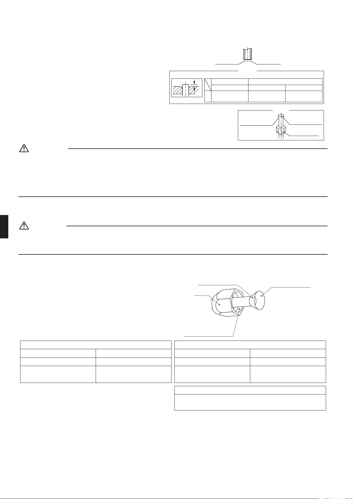
3. Flaring the pipe end
1) Cutthepipeendwithapipecutter.
2) Removeburrswiththecutsurfacefacing
downwardsothatthechipsdonotenterthepipe.
3) Putthearenutonthepipe.
4) Flarethepipe.
5) Checkthatthearingisproperlymade.
WARNING
•Donotusemineraloilonaredpart.
•Preventmineraloilfromgettingintothesystemasthiswouldreducethelifetimeoftheunits.
•Neverusepipingwhichhasbeenusedforpreviousinstallations.Onlyusepartswhicharedeliveredwiththeunit.
•NeverinstalladriertothisR410Aunitinordertoguaranteeitslifetime.
•Thedryingmaterialmaydissolveanddamagethesystem.
•Incompletearingmaycauserefrigerantgasleakage.
4. Refrigerant piping
CAUTION
•Usethearenutxedtothemainunittopreventitfromcrackinganddeterioratingfromage.
•Topreventgasleakage,applyrefrigerationoilonlytotheinnersurfaceoftheare.(UserefrigerationoilforR410A.)
•Usetorquewrencheswhentighteningthearenutstopreventdamagetothearenutsandgasleakage.
Flare nut tightening torque
Liquid side
3/8 inch (9.5mm)
24.1-29.4ft • lbf
(32.7-39.9N • m)
Gas side
5/8 inch (15.9mm)
45.6-55.6ft • lbf
(61.8-75.4N • m)
Valve cap tightening torque
Liquid side
3/8 inch (9.5mm)
15.9-20.2ft • lbf
(21.6-27.4N • m)
Gas side
5/8 inch (15.9mm)
35.5-44.0ft • lbf
(48.1-59.7N • m)
Service port cap tightening torque
Do not apply refrigeration
oil to the outer surface.
Flare nut
Apply refrigeration oil to
the inner surface of the
flare.
Do not apply refrigeration oil to
the flare nut to avoid tightening
with excessive torque.
[Apply oil]
• Align the centers of both flares and tighten the flare
nuts 3 or 4 turns by hand. Then tighten them fully with
the torque wrenches.
7.9-10.8ft • lbf
(10.8-14.7N • m)
(Cut exactly at
right angles.)
Remove burrs.
Set exactly at the position shown below.
A
Flaring
Die
Check
Flare’s inner surface
must be flaw-free.
The pipe end must
be evenly flared in a
perfect circle.
Make sure that the
flare nut is fitted.
A
0-0.020 inch
(0-0.5mm)
Clutch-type
Flare tool for R410A
0.039-0.059 inch
(1.0-1.5mm)
Clutch-type (Rigid-type)
0.059-0.079 inch
(1.5-2.0mm)
Wing-nut type (Imperial-type)
Conventional flare tool
01_EN_3P300674-3.indd 6 10/13/2011 2:23:52 PM
7
■
English
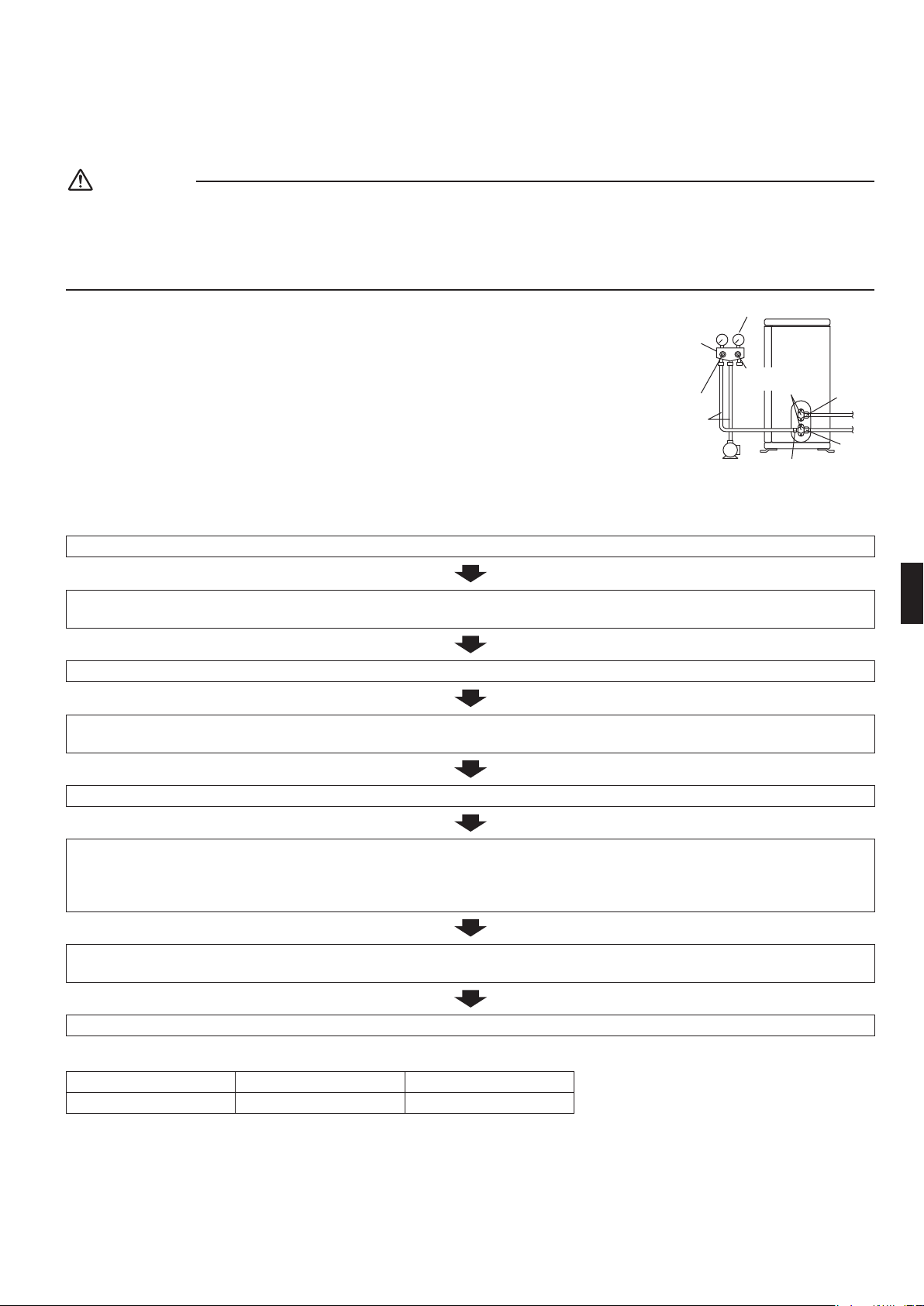
5. Purging air and checking gas leakage
WARNING
•Donotmixanysubstanceotherthanthespeciedrefrigerant(R410A)intotherefrigerationcycle.
•Whenrefrigerantgasleaksoccur,ventilatetheroomassoonandasmuchaspossible.
•R410A,aswellasotherrefrigerants,shouldalwaysberecoveredandneverbereleaseddirectlyintotheenvironment.
•
UseavacuumpumpforR410Aexclusively.Usingthesamevacuumpumpfordifferentrefrigerantsmaydamagethevacuum
pumportheunit.
•Whenpipingworkiscompleted,itisnecessarytopurgetheairandcheckforgas
leakage.
•Ifusingadditionalrefrigerant,performairpurgingfromtherefrigerantpipesandindoor
unitusingavacuumpump,thenchargeadditionalrefrigerant.
•Useahexagonalwrench(3/16inch(4mm))tooperatethestopvalverod.
•Allrefrigerantpipejointsshouldbetightenedwithatorquewrenchatthespecied
tighteningtorque.
1) Connectprojectionsideofcharginghose(whichcomesfromgaugemanifold)togasstopvalve’sserviceport.
2) Fullyopengaugemanifold’slow-pressurevalve(Lo)andcompletelycloseitshigh-pressurevalve(Hi).
(High-pressurevalvesubsequentlyrequiresnooperation.)
3) Dovacuumpumpingandmakesurethatthecompoundpressuregaugereads–29.9inHg(–0.1MPa).*1
4) Closegaugemanifold’slow-pressurevalve(Lo)andstopvacuumpump.
(Keepthisstateforafewminutestomakesurethatthecompoundpressuregaugepointerdoesnotswingback.)*2
5) Removecapsfromliquidstopvalveandgasstopvalve.
6) Turntheliquidstopvalve’srod90degreescounterclockwisewithahexagonalwrenchtoopenvalve.
Closeitafter5seconds,andcheckforgasleakage.
Usingsoapywater,checkforgasleakagefromindoorunit’sareandoutdoorunit’sareandvalverods.
Afterthecheckiscomplete,wipeallsoapywateroff.
7) Disconnectcharginghosefromgasstopvalve’sserviceport,thenfullyopenliquidandgasstopvalves.
(Donotattempttoturnvalverodbeyonditsstop.)
8) Tightenvalvecapsandserviceportcapsfortheliquidandgasstopvalveswithatorquewrenchatthespeciedtorques.
*1.Pipelengthvs.vacuumpumpruntime
Pipelength Upto49.2ft(15m) Morethan49.2ft(15m)
Runtime Notlessthan10min. Notlessthan15min
*2.Ifthecompoundpressuregaugepointerswingsback,refrigerantmayhavewatercontentoraloosepipejointmayexists.Check
allpipejointsandretightennutsasneeded,thenrepeatsteps2)through4).
Gauge
manifold
Compound
pressure gauge
Pressure meter
Low-pressure
valve
High-pressure
valve
Charging
hoses
Vacuum pump
Valve caps
Service port
Liquid
stop
valve
Gas
stop
valve
01_EN_3P300674-3.indd 7 10/13/2011 2:23:52 PM
8
■
English
Outdoor Unit Installation
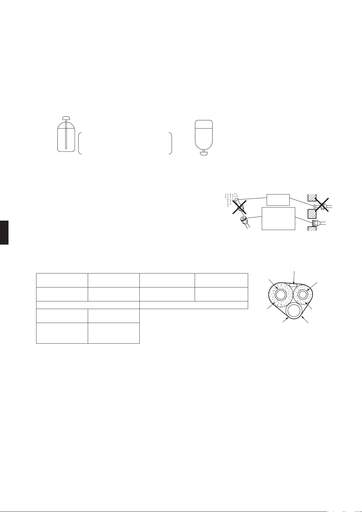
6. Relling the refrigerant
Checkthetypeofrefrigeranttobeusedonthemachinenameplate.
Precautions when adding R410A
Fill from the gas pipe in liquid form.
Itisamixedrefrigerant,soaddingitingasformmaycausetherefrigerantcompositiontochange,preventingnormaloperation.
1) Beforelling,checkwhetherthecylinderhasasiphonattachedornot.(Itshouldhavesomethinglike“liquidllingsiphon
attached”displayedonit.)
Filling a cylinder with an attached siphon
Stand the cylinder upright when
filling.
There is a siphon pipe inside, so the
cylinder need not be upside-down to
fill with liquid.
Filling other cylinders
Turn the cylinder upside-down
when filling.
•BesuretousetheR410Atoolstoensurepressureandtopreventforeignobjectsentering.
7. Refrigerant piping work
7-1 Caution on pipe handling
1) Protecttheopenendofthepipeagainstdustandmoisture.
2) Allpipebendsshouldbeasgentleaspossible.Useapipebenderfor
bending.
7-2 Selection of copper and heat insulation materials
Whenusingcommercialcopperpipesandttings,observethefollowing:
1) Insulationmaterial:Polyethylenefoam
Heattransferrate:0.041to0.052W/mK(0.024to0.030Btu/fth°F(0.035to0.045kcal/mh°C))
BesuretouseinsulationthatisdesignedforusewithHVACSystems.
2) Besuretoinsulateboththegasandliquidpipingandtoprovideinsulation
dimensionsasbelow.
Gasside Liquidside
Gaspipethermal
insulation
Liquidpipethermal
insulation
O.D.5/8inch
(15.9mm)
O.D.3/8inch
(9.5mm)
I.D.5/8-25/32inch
(16-20mm)
I.D.15/32-19/32inch
(12-15mm)
Minimumbendradius Thickness13/32inch(10mm)Min.
1-15/16inch(50mm)
ormore
1-3/16inch(30mm)
ormore
Thickness
0.039inch(1.0mm)
(C1220T-O)
Thickness
0.031inch(0.8mm)
(C1220T-O)
•Useseparatethermalinsulationpipesforgasandliquidrefrigerantpipes.
Wall
If no flare cap is
available, cover the
flare mouth with
tape to keep dirt or
water out.
Be sure to
place a cap.
Rain
Gas pipe
Liquid pipe
Gas pipe
insulation
Liquid pipe
insulation
Finishing tape
Drain hose
Inter-unit wire
01_EN_3P300674-3.indd 8 10/13/2011 2:23:53 PM
9
■
English
Pump Down Operation
In order to protect the environment, be sure to pump down when relocating or disposing of the unit.
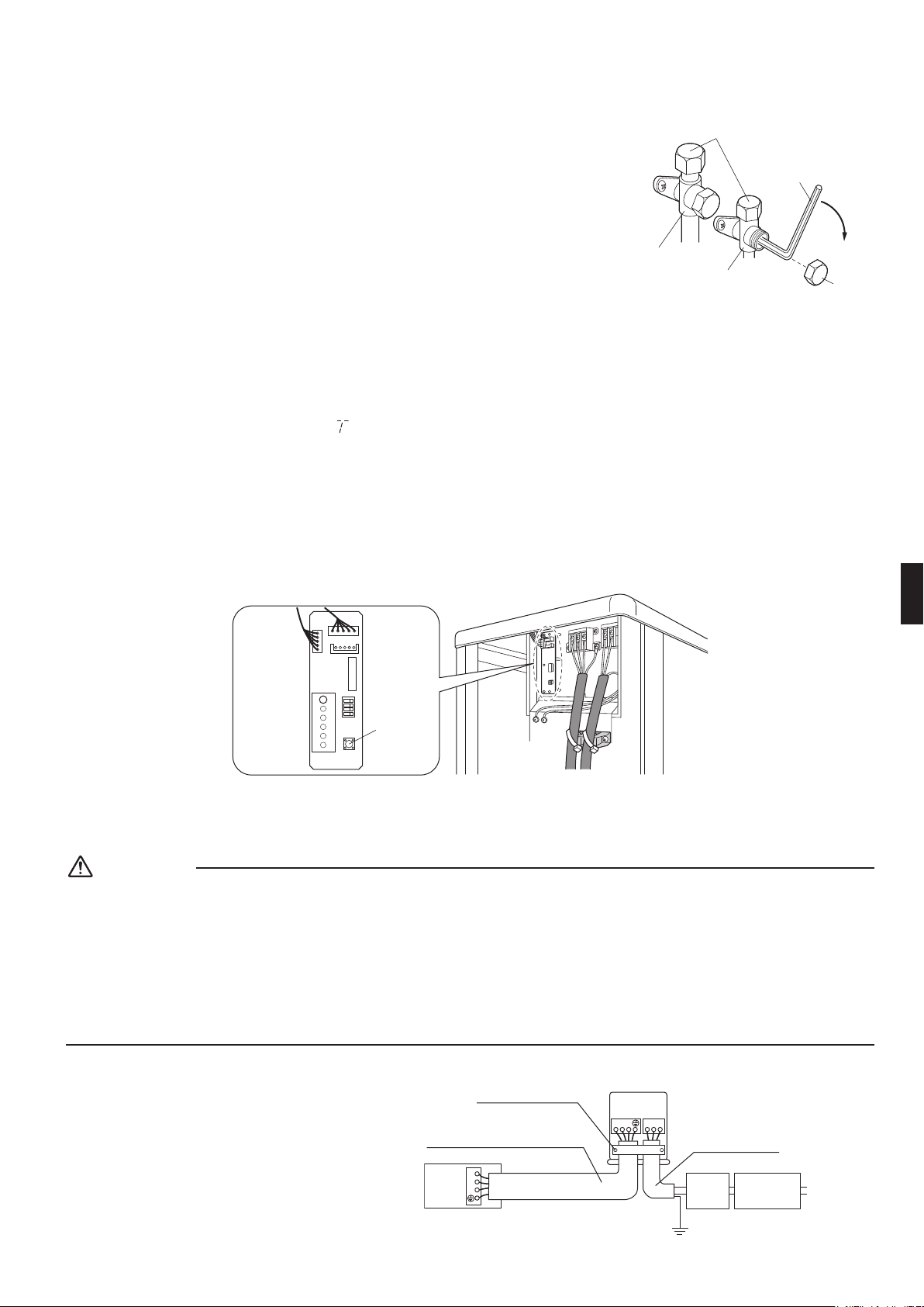
1) Removethevalvecapfromliquidstopvalveandgasstopvalve.
2) Carryoutforcedcoolingoperation.
3) After5to10minutes,closetheliquidstopvalvewithahexagonalwrench.
4) After2to3minutes,closethegasstopvalveandstopforcedcoolingoperation.
Forced cooling operation
■
Using the indoor unit ON/OFF switch
PresstheindoorunitON/OFFswitchforatleast5seconds.(Theoperationwillstart.)
• Forcedcoolingoperationwillstopautomaticallyafteraround15minutes.
Tostoptheoperation,presstheindoorunitON/OFFswitch.
■
Using the indoor unit’s remote controller
1) Press“MODE”buttonandselectthecoolingmode.
2) Press“ON/OFF”buttontoturnonthesystem.
3) Pressbothof“TEMP”buttonand“MODE”buttonatthesametime.
4) Press“MODE”buttontwice.(
willbedisplayedandtheunitwillenterforcedcoolingoperation.)
• Forcedcoolingoperationwillstopautomaticallyafteraround30minutes.
Tostoptheoperaion,press“ON/OFF”button.
■
Using the outdoor unit forced cooling operation switch
Forcedcoolingoperationcanbeperformedwhentheoutdoorunitforcedcoolingoperationswitchispressedwithin
around3minutesafterpowerissupplied.
Presstheswitch(SW1).(Theoperationwillstart.)
• Forcedcoolingoperationwillstopautomaticallyafteraround15minutes.
Tostoptheoperation,presstheswitch(SW1).
LED-A
SW4
ON
A B CD
S102
SW1
S2
Forced
cooling
operation
switch (SW1)
Wiring
WARNING
•
Donotusetappedwires,strandedwires,extensioncords,orstarburstconnections,astheymaycauseoverheating,electricalshock,orre.
•Donotuselocallypurchasedelectricalpartsinsidetheproduct.(Donotbranchthepowerforthedrainpump,etc.,fromthe
terminalblock.)Doingsomaycauseelectricshockorre.
•Besuretoinstallagroundfaultcircuitinterrupterbreaker.(Onethatcanhandlehigherharmonics.)
(Thisunitusesaninverter,whichmeansthatitmustbeusedagroundfaultcircuitinterrupterbreakercapablehandling
harmonicsinordertopreventmalfunctioningofthegroundfaultcircuitinterrupterbreakeritself.)
•Useanall-poledisconnectiontypebreakerwithatleast1/8inch(3mm)betweenthecontactpointgaps.
•Whencarryingoutwiringconnection,takecarenottopullattheconduit.
•Donotconnectthepowerwiretotheindoorunit.Doingsomaycauseelectricshockorre.
•Donotturnonthesafetybreakeruntilallworkiscompleted.
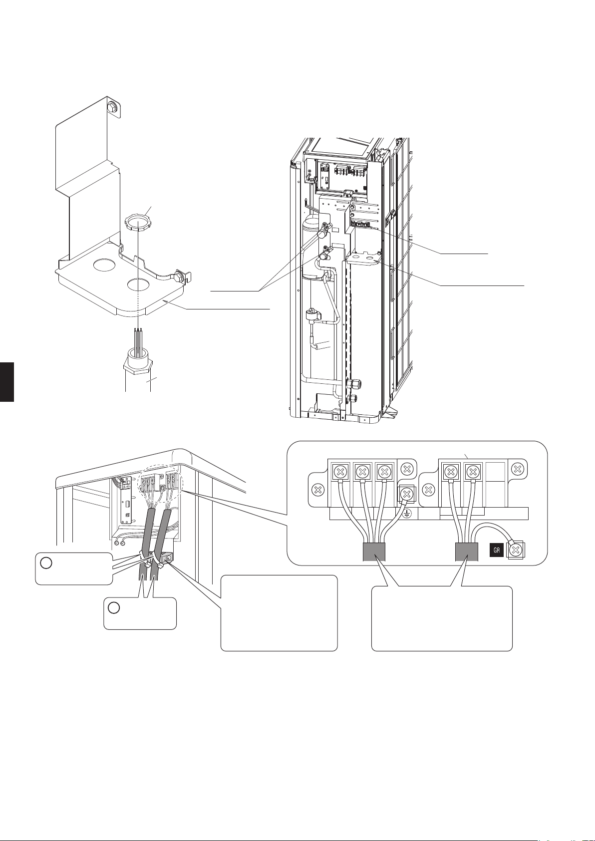
1)
Striptheinsulationfromthewire(3/4inch(20mm)).
2) Connecttheconnectionwiresbetweenthe
indoorandoutdoorunitssothattheterminal
numbersmatch.Tightentheterminalscrews
securely.Werecommendaathead
screwdriverbeusedtotightenthescrews.
Close
valve cap
Hexagonal
wrench
Service port
Liquid stop valve
Gas stop valve
1
2
3
1 2 3
Safety
breaker
20A
Ground fault
circuit interrupter
Ground
Firmly fix the wires with
the terminal screws.
Outdoor unit
Indoor
unit
Power supply
60Hz 208-230V
L
1
L
2
Use AWG16 if the connection wire
length is less than 32.8ft (10m), or
AWG14 if it is 32.8ft (10m) or more.
Use AWG 14 wires.
GR
01_EN_3P300674-3.indd 9 10/13/2011 2:23:53 PM
10
■
English
Wiring
<Methodofmountingconduit>
Passwiresthroughtheconduitandsecurethemwithalocknut.
Wire retainer
Conduit mounting plate
Service port
Lock nut
Conduit
1/2 inch (21.3mm)
Conduit mounting plate
Tube
(Accessory)
Binding band
(Accessory)
Secure the wires firmly
using the binding band, as
shown in the figure.
Secure firmly, making sure
no outside pressure is
exerted on the terminals.
Power supply terminal block
L1 L2
1 2 3
• Use the specified wires and
connect them securely.
• Shape the wires so that there
is no lifting of the service hatch
or other structural parts.
D
C
Observethenotesmentionedfollowingwhenwiringtothepowersupplyterminalblock.
Precautionstobetakenforpowersupplywiring.
01_EN_3P300674-3.indd 10 10/13/2011 2:23:54 PM
11
■
English
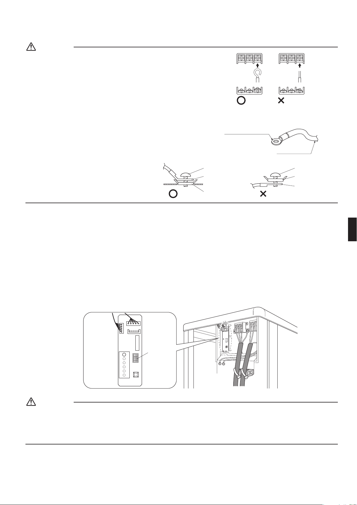
CAUTION
•Whenconnectingtheconnectionwirestotheterminalblock
usingasinglecorewire,besuretoperformcurling.
Problemswiththeworkmaycauseheatandres.
•Ifthestrandedwiresmustbeused,makesuretousetheround
crimp-styleterminalforconnectiontothepowersupplyterminal
block.Placetheroundcrimp-styleterminalsonthewiresupto
thecoveredpartandsecureinplace.
Stranded wire
Round crimp-style
terminal
•Groundterminalinstallation
Usethefollowingmethodwheninstallingthe
roundcrimp-styleterminal.
Good Wrong
Round crimp-
style terminal
Flat washer
Screw
Flat washer
Round crimp-
style terminal
Screw
3) Pullthewireandmakesurethatitdoesnotdisconnect.Thenxthewireinplacewithawirestop.
Facility Setting
(cooling at low outdoor temperature)
This function is designed for facilities such as equipment or computer rooms. It is never to be used in a
residence or ofce where people occupy the space.
1) Youcanexpandtheoperationrangeto14°F(–10°C)byturningonswitchB(SW4)onthePCB.Iftheoutdoortemperaturefalls
to–0.4°F(–18°C)orlower,theoperationwillstop.Iftheoutdoortemperaturerises,theoperationwillstartagain.
LED-A
SW4
ON
A B C D
S102
SW1
S2
Turn on
switch B.
CAUTION
•Iftheoutdoorunitisinstalledwheretheheatexchangeroftheunitisexposedtodirectwind,provideawindbreakwall.
•Intermittentnoisesmaybeproducedbytheindoorunitduetotheoutdoorfanturningonandoffwhenusingfacilitysettings.
•Donotplacehumidiersorotheritemswhichmightraisethehumidityinroomswherefacilitysettingsarebeingused.
Ahumidiermightcausedewcondensationfromtheindoorunitoutletvent.
•Usetheindoorunitatthehighestlevelofairowrate.
Stripping wire at terminal block
Good Wrong
01_EN_3P300674-3.indd 11 10/13/2011 2:23:55 PM
12
■
English
Trial Operation and Testing
1. Trial operation and testing
1-1Measurethesupplyvoltageandmakesurethatitfallsinthespeciedrange.
1-2Trialoperationshouldbecarriedoutineithercoolingorheatingmode.
■
Forheatpump
•Incoolingmode,selectthelowestprogrammabletemperature;inheatingmode,selectthehighestprogrammable
temperature.
1) Trialoperationmaybedisabledineithermodedependingontheroomtemperature.
2) Aftertrialoperationiscomplete,setthetemperaturetoanormallevel(78°Fto82°F(26°Cto28°C)incoolingmode,
68°Fto75°F(20°Cto24°C)inheatingmode).
3) Forprotection,thesystemdisablesrestartoperationfor3minutesafteritisturnedoff.
■
Forcoolingonly
•Selectthelowestprogrammabletemperature.
1) Trialoperationincoolingmodemaybedisableddependingontheroomtemperature.
2) Aftertrialoperationiscomplete,setthetemperaturetoanormallevel(78°Fto82°F(26°Cto28°C)).
3) Forprotection,thesystemdisablesrestartoperationfor3minutesafteritisturnedoff.
1-3Carryoutthetestoperationinaccordancewiththeoperationmanualtoensurethatallfunctionsandparts,
suchasnmovement,areworkingproperly.
•Theairconditionerrequiresasmallamountofpowerinitsstandbymode.Ifthesystemisnottobeusedforsome
timeafterinstallation,shutoffthecircuitbreakertoeliminateunnecessarypowerconsumption.
•Ifthecircuitbreakertripstoshutoffthepowertotheairconditioner,thesystemwillrestoretheoriginaloperation
modewhenthecircuitbreakerisopenedagain.
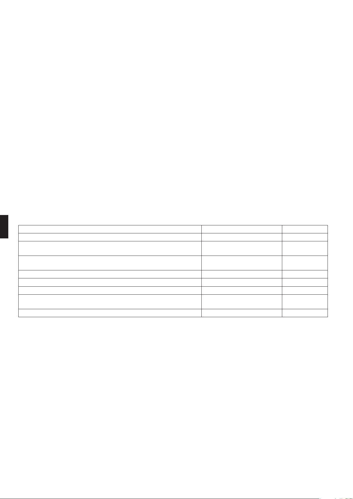
2. Test items
Testitems Symptom Check
Indoorandoutdoorunitsareinstalledproperlyonsolidbases. Fall,vibration,noise
Norefrigerantgasleaks.
Incompletecooling/heating
function
Refrigerantgasandliquidpipesandindoordrainhoseextensionare
thermallyinsulated.
Waterleakage
Draininglineisproperlyinstalled. Waterleakage
Systemisproperlygrounded. Electricalleakage
Thespeciedwiresareusedforinter-unitwiring. Inoperativeorburndamage
Indoororoutdoorunit’sairinletorairoutlethasclearpathofair.
Stopvalvesareopened.
Incompletecooling/heating
function
Indoorunitproperlyreceivesremotecontrolcommands. Inoperative
01_EN_3P300674-3.indd 12 10/13/2011 2:23:55 PM
3P300674-3
M11B136
(1111)
HT
Two-dimensional bar code is a code
for manufacturing.
00_CV_3P300674-3.indd 2 10/21/2011 1:32:12 PM