Loading ...
Loading ...
Loading ...
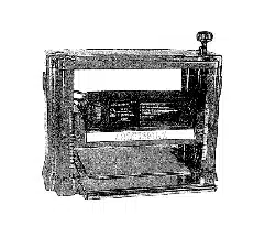
DEPTH OF CUT
Thickness planing refers to the sizing of lumber to a
desired thickness while creating a level surface parallel
to the opposite side of the board.
= Quality of thickness planing depends on the opera-
tot's judgement about the depth of cut
,, Depth of cut depends on the width, hardness, damp-
ness, grain direction and grain structure of the wood.
° Maximum thickness of wood which can be removed
in one pass is _=" for planing operations on work-
piece up to 5" wide. Workpiece must be positioned
away from the center tab in the rollercase to cut _/3_".
° Maximum thickness of wood which can be removed
in one pass is ',%"for planing operations on work-
piece from 5" up to 12V2"wide.
o For optimum planing performance, the depth of cut
should be tess than ',4¢'..
= Board should be planed with shallow cuts until the
work has a level side. Once level surface has been
created, flip the lumber and create parallel sides.
° Plane alternate sides until the desired thickness is
obtained When half of total depth of cut is taken from
each side, the board will have a uniform moisture con-
tent and additional drying will not cause itto warp.
o Depth of cut should be shallower when work is wider..
° When planing hardwood, take light cuts or plane the
wood in thin widths.
° Make test cut when working with a new type of
board or different kind of operation.
= Check accuracy of test cut prior to working on fin-
ished product
ADJUSTING DEPTH OF CUT
Refer to Figures 8 and 9, pages 14 and 16.
Board thickness which the planer will produce is indicat-
ed by either scale (Fig. 9, No 13) on the side.
Thickness isadjusted by rotating the handle (Fig 8, No 1)
clockwise to raise the blade height..To reduce the blade
height, rotate the handle counterclockwise.
= Do not set blade below '¾2"°Do not plane a board
which is less than a V2" thick.
° Blade height will be moved '/,_" with every complete
revolution of the handle
a Make a test cut on a piece of wood and measure the
thickness produced.
The planer will produce uneven depth of cut (tapered cut)
if the roIlercase (Fig. 8, No. 46) is not parallel with the base
(Fig 9, No..17). To restore parallelism of the rollercase with
the base:
o Unplug the planer and turn itoff
o Clamp a vise plier on the left side of the shaft (Fig 9,
No..8) next to the bevel gear (Fig. 9, No, 3)
= Remove E-ring (Fig. 9, No..4) and disengage right
bevel gear (Fig. 9, No 3) on the right elevation screw
(Fig. 9, No. 2).
o Slowly rotate handle (Fig, 8, No. 1) to raise or lower
the cutterhead. Rotate clockwise to raise roUercase,
counterclockwise to lower rollercase Rollercase wilt
be moved by _004" with every turn of the beveled
gear by one tooth.
o After moving roIlercase the required distance, make
sure both beveled gears (Fig 9, No. 3) are engaged
and secured with E-ring
o Release and remove the vise plier
o Make a test cut to make sure the adjustment was
appropriate
• Add grease to bevel gears if necessary°
When the depth of cut adjustment is operating correctly,
loosen the pan head screw (Fig. 8, No..5) and set the
indicator (Fig. 8, No. 30) to show the thickness pro-
duced Make sure that the indicator is positioned cot*
rectly_
ADJUSTING CUTTERHEAD HEIGHT
Refer to Figures 8 and 9, pages 14 and 16._
The depth of cut of the planer is adjusted by raising or
lowering the cutterhead (Fig, 8, No i1)..
Rotate the handle (Fig. 8, No. 1) to raise or lower the
cutterhead to the desired position.
The scale (Fig. 9, No. 13) and indicator (Fig. 8, No. 30)
can be used when adiusting the cutterhead heighL
ADJUSTING SUPPORT ROLLERS
Refer to Figure 9, page 16.
° The support rollers (No. 12) should be adjusted to
help keep the portion of work which is outside the
planer in line.
o Use a straightedge to align the roller plate so the
support roller height is even with the base cover' (No.
21).
o Loosen nuts (No, 15) and adjust height with the hex
head bolts (No. 21).
• Make sure that both of the hex bolts hold the posi-
tion of the roller plate.. Hold the hex bolt with an open
end wrench and secure the adjustment by tightening
the nut.
o Check the alignment of the support roller at each
end with a straight edge..
ADJUSTING BLADE HEIGHT
Refer to Figures 6 and 8, pages 7 and 14_
The knife gauge assembly (see Assembly, page 3) is
required to make replacing or adjusting planing blades
(Fig 8, No. 23) more convenient..
° Unplug the planer and turn it off.
o Loosen and remove two socket head bolts and
washers (Fig 8, Nos, 8 and 9).
° Remove blade guard (Fig. 8, No.,7)_
= Turn cutterhead (Fig. 8, No. 11) carefully to access
one blade
CAUTION: Blades are sharp.
6
Loading ...
Loading ...
Loading ...