
EN
DIGITAL MIXING CONSOLE
TF Editor V4.0 User's Guide

User’s Guide
TF Editor
-
2
-
Special notices
• Copyrights of the software and this document are the exclusive property of Yamaha Corporation.
• Copying or modifying the software or reproduction of this document, by any means, whether in whole or in part, is expressly
forbidden without the written consent of Yamaha Corporation.
• Copying of commercially available music sequence data and/or digital audio files is strictly prohibited except for your personal
use.
• Yamaha Corporation makes no representations or warranties with regard to the use of the software and documentation and
cannot be held responsible for the results of the use of the software and this document.
• Illustrations of product screens that appear in this document are for instructional purposes, and may appear somewhat different
from the screens that are displayed on your computer.
• Information about system software and changes to certain product functions or specification due to updates to the software is
available at the Yamaha Pro Audio web site.
• Windows is a registered trademark of Microsoft Corporation in the United States of America and other countries.
• Mac and Macintosh are trademarks of Apple Inc., registered in the U.S. and other countries.
• The company names and product names in this document are the trademarks or registered trademarks of their respective
companies.
Note
• Part of this software uses open source software. License information is available in the Legal screen.

Table of contents
User’s Guide
TF Editor
-
3
-
Table of contents
Special notices ................................................................................................................................................ 2
Note............................................................................................................................................................... 2
Basic setup and operation ..................................................................................... 4
What is TF Editor?........................................................................................................................................... 4
Connecting TF Editor to the console............................................................................................................... 4
Startup ........................................................................................................................................................... 4
Basic operations.............................................................................................................................................. 4
Syncing TF Editor and your console ................................................................................................................ 5
Offline editing ................................................................................................................................................ 6
Menu bar ....................................................................................................................................................... 6
Screen areas........................................................................................................... 8
HOME/LIBRARY area ....................................................................................................................................... 8
CONNECT area .............................................................................................................................................. 9
FADER BANK area ........................................................................................................................................... 9
MUTE area...................................................................................................................................................... 9
Menu area .................................................................................................................................................... 10
SENDS ON FADER area................................................................................................................................. 10
Channel strip area......................................................................................................................................... 11
Master/FX/ST IN strip area............................................................................................................................ 11
Toolbar................................................................................................................. 12
SCENE screen ............................................................................................................................................... 13
METER screen ............................................................................................................................................... 16
MONITOR screen ......................................................................................................................................... 17
SETUP screen ................................................................................................................................................ 19
Main display area................................................................................................. 30
LIBRARY screen ............................................................................................................................................. 30
SOFT KEYBOARD screen ............................................................................................................................... 32
OVERVIEW screen ......................................................................................................................................... 33
SELECTED CHANNEL screen ......................................................................................................................... 38
INPUT screen................................................................................................................................................ 45
EQ screen ..................................................................................................................................................... 48
GATE screen ................................................................................................................................................. 51
COMP screen ............................................................................................................................................... 53
FX screen (FX1/2, InsFX1–6) ......................................................................................................................... 55
SEND TO AUX screen ................................................................................................................................... 62
ASSIGN screen.............................................................................................................................................. 63
AUTOMIXER screen ...................................................................................................................................... 64
CH VIEW screen............................................................................................................................................ 66
CH NAME screen .......................................................................................................................................... 78
GEQ screen................................................................................................................................................... 79
OUTPUT screen ............................................................................................................................................ 81
SEND FROM screen ...................................................................................................................................... 82
DCA ASSIGN screen...................................................................................................................................... 83
DELAY screen................................................................................................................................................ 84
Screens of the File Menu...................................................................................... 85
Manage Library/Scene screen ....................................................................................................................... 85
Input List screen ........................................................................................................................................... 87
Reference ............................................................................................................. 89
Error messages.............................................................................................................................................. 89
TF Editor shortcuts........................................................................................................................................ 90
Index .................................................................................................................... 91

Basic setup and operation
User’s Guide
TF Editor
-
4
-
Basic setup and operation
What is TF Editor?
TF Editor is a computer program that allows you to use your computer to edit TF series console settings while away from the console
(offline mode), and operate the console using the computer while it is connected to the console (online mode).
Connecting TF Editor to the console
TF Editor connects to the TF series console using a network connection. The computer and console can connect to each other if
they are connected to the same network. For information about network settings, refer to the Installation Guide for TF Editor.
Startup
When you start TF Editor, you will be prompted to select the model number of your TF series console.
Select the model number and then click the [Start] button.
This setting is saved; you do not need to select the model number the next time you start TF Editor.
Basic operations
Mouse wheel
You can use your computer's mouse wheel just as you would use the console's [TOUCH AND TURN] knob.
Computer keyboard
You can use your computer's keyboard just as you would use the console's SOFT KEYBOARD screen.
Touch screen
You can use your computer's touchscreen just as you would use the console's touchscreen display.
NOTE
• Only one TF Editor session can run on a computer at a time.
• When computer (running TF Editor) and iPads (running TF StageMix) are connected to the console, the console supports up to three
simultaneous connections. Only one computer running TF Editor can connect to the console at a time.
Basic setup and operation
User’s Guide
TF Editor
-
5
-
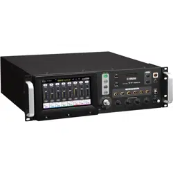
Syncing TF Editor and your console
When you first start TF Editor, its settings will be different from your console's settings. Therefore, you will need to sync TF Editor
with your console. This is performed using the CONNECT area of TF Editor.
Preparation
Before you can sync, you need to configure the network interface.
1. Select SETUP Network Interface.
2. Select the desired network interface from the list of available items.
3. Click [OK].
Operation
1. Click the status button in the CONNECT area.
2. In the CONNECT screen, select the console and the direction of the data sync.
Only consoles that correspond to the model number you selected when you first launched TF Editor are displayed.
When the maximum number of TF Editor and TF StageMix sessions (total: 3) are already connected to the TF series console, a "restricted"
mark is displayed to the left of the IP address. Even if you select a TF series console that does not have a "restricted" mark displayed next to
it and click the CONNECT button, depending on the connection status of other TF Editor and TF StageMix sessions, a message may be
displayed that indicates you cannot connect to the console.
The following sync directions are available.
"TF***" indicates the model name of the TF Series you are using.
3. Enter the Administrator's password if you have set it to the Administrator of TF series.
4. Click [Connect].
Do not operate the console while data is being synced.
CONNECT area
TF*** PC Console settings are copied to TF Editor.
TF*** PC TF Editor settings are copied to the console.
Basic setup and operation
User’s Guide
TF Editor
-
6
-
Offline editing
You can switch between online and offline mode by clicking the status button in the CONNECT area. When OFFLINE is displayed,
you can use TF Editor without connecting your computer to the console. When you're ready to copy the new settings from TF Editor
to the console, click the status button and select [TF*** PC] as the sync direction.
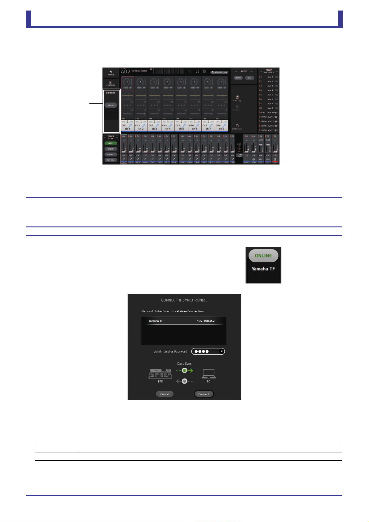
Menu bar
File menu
Allows you to work with files.
TF Editor supports the following file types.
Each item in the menu is displayed below.
Load
Allows you to select a TFF file and load it into TF Editor.
Save
Saves the current settings by overwriting the existing TFF file.
Save As
Allows you to save the current settings as a new TFF file.
Manage Library/Scene
Opens the Manage Library/Scene screen (page 85), where you can manage Library and Scene data.
This item is not available when the program is connected to the console (online mode).
Input List
Opens the Input List screen (page 87), where you can view and set channel names, channel colors, channel icons, and
patching for input channels, output channels, and DCA groups.
Get New QuickPro Presets
Opens your web browser and takes you to the web page where you can download QuickPro Presets.
Initialize Memory
This item is not available when the program is connected to the console (online mode).
Current memory: Allows you to initialize the current memory of TF Editor.
The following data is initialized: mixing data and setup data.
All Memory: Allows you to initialize all of TF Editor's memory.
The following data is initialized: all Scene data, all Preset data, mixing data, and setup data.
Exit
Exits TF Editor.
File extension Description
.TFP Used to store data for one Preset in a single file.
.TFS Used to store data for one Scene in a single file.
.TFF Used to store all mixer settings.
NOTE
• You can save TFF files created using TF Editor to a USB storage device that is connected to your computer. Later, if you connect the USB storage
device to the console's USB connector, you can load the data directly into the console. Similarly, you can use the console to save TFF files to its
USB storage device, and then connect the device to your computer and load the data into TF Editor.
• You can drag and drop TFP files within the TF Editor screen to save and load them. For more information, refer to "LIBRARY screen" (page 31)
in "Importing and exporting Presets".
NOTE
An Internet connection is required in order to download QuickPro Presets.

Basic setup and operation
User’s Guide
TF Editor
-
7
-
Setup menu
Allows you to enable and disable the features explained below. When a feature is enabled, a checkmark is displayed in the menu.
Select the item again to remove the checkmark and disable the feature.
Channel Select Link
Determines whether the channel selection is also synced when syncing data between your computer and the console.
Network Interface
Allows you to select the network port used for communication between your computer and the console.
Selections displayed here vary depending on your computer and network environment.
Confirmation
Determines whether a confirmation dialog is displayed when you use Store, Recall, Input Select, or Output Patch features.
A confirmation dialog is displayed when this item is enabled.
Display Delay Scale
You can select the desired units (frames, meters, feet, milliseconds) used for the delay time displayed in the DELAY box.
Frame Rate
Select the frame rate if you wish to configure the delay in units of frames.
Home Button Function
Selects the section to display when clicking on the HOME button. When "CH Strip & SEL CH" is selected, click the HOME
button to switch between the CH Strip section and Selected Channel section.
Window menu
Allows you to change how screen content is displayed.
Zoom
Allows you change the display size to 100%, 150%, or 200%.
Maximize
Maximizes TF Editor screen content.
When TF Editor is maximized, the FADER area (page 10) is expanded so that more channels can be displayed.
Help menu
Help
Opens the Manual Library in your computer's web browser.
About
Displays version information about TF Editor.
Legal
Displays license information about TF Editor.
NOTE
An Internet connection is required to access the Manual Library.
Screen areas
User’s Guide
TF Editor
-
8
-
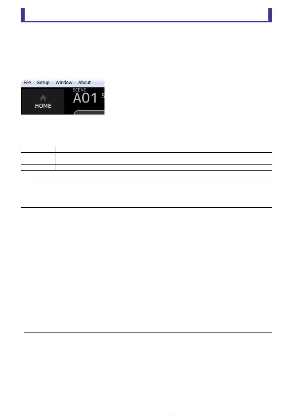
Screen areas
1 HOME/LIBRARY area (page 8)
2 CONNECT area (page 9)
3 FADER BANK area (page 9)
4 MUTE area (page 9)
5 Menu area (page 10)
6 SENDS ON FADER area (page 10)
7 Channel strip area (page 11)
8 Master/FX/ST IN strip area (page 11)
9 Toolbar area (page 12)
0 Main display area (page 30)
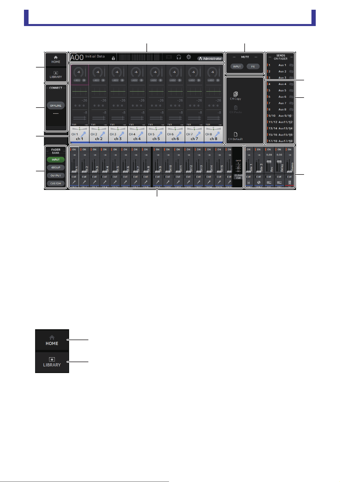
HOME/LIBRARY area
1 HOME button
Displays the OVERVIEW screen (page 33) in the main display area.
2 LIBRARY button
Displays the LIBRARY screen (page 30) in the main display area.
䐧䐢
䐟
䐠
䐨
䐤
䐣
䐦
䐡
䐥
ձ
ղ
Screen areas
User’s Guide
TF Editor
-
9
-
CONNECT area
FADER BANK area
MUTE area
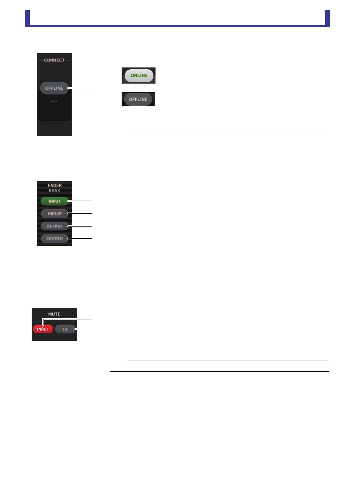
1 Status button
Click this button to switch between online and offline modes.
If TF Editor is properly connected to your console, TF Editor is operating
in online mode and ONLINE is displayed here. In online mode,
parameters are linked between TF Editor and the console.
If TF Editor is not connected to your console or if there is a problem with
the connection, TF Editor is operating in offline mode and OFFLINE is
displayed here.
In offline mode, parameters are not linked between TF Editor and the
console.
Allows you to select which fader bank is displayed in the channel strip area (page 11).
1 INPUT bank
Displays the console's INPUT1/INPUT2 bank.
For TF5 and TF3 consoles, CH 1–40 are displayed in the channel area; for TF1 console and
TF-RACK, CH 1–32 are displayed.
2 GROUP bank
Displays the console's GROUP bank. Eight channel strips for DCA 1–8 are displayed in
addition to the channel strips assigned to each DCA channel (24 channels strips for TF5;
16 for TF3; 8 for TF1 and TF-RACK).
3 OUTPUT bank
Displays AUX 1–19/20, MONITOR, SUB, and MATRIX1–MATRIX4.
4 CUSTOM bank
Displays the custom fader bank.
Turns the console's mute feature on and off.
1 INPUT button
Mutes all of the console's input channels. This button lights when the mute is turned on.
2 FX button
Mutes the console's FX module. Insert effects assigned to AUX 9/10–19/20 will be
bypassed. This button lights when the mute is turned on.
ձ
NOTE
You can choose whether the selected channel is linked between TF Editor and the console.
This is determined by the Channel Select Link setting in the Setup menu (page 7).
ձ
ղ
ճ
մ
ձ
ղ
NOTE
If you turn on MUTE SAFE for input channels and FX channels, they will be exempted from the mute group.
Screen areas
User’s Guide
TF Editor
-
10
-
Menu area
SENDS ON FADER area
Displays the options that are available for the screen displayed in the main display area.
For information about the items displayed in the Menu area, refer to the explanation for the
corresponding screen.
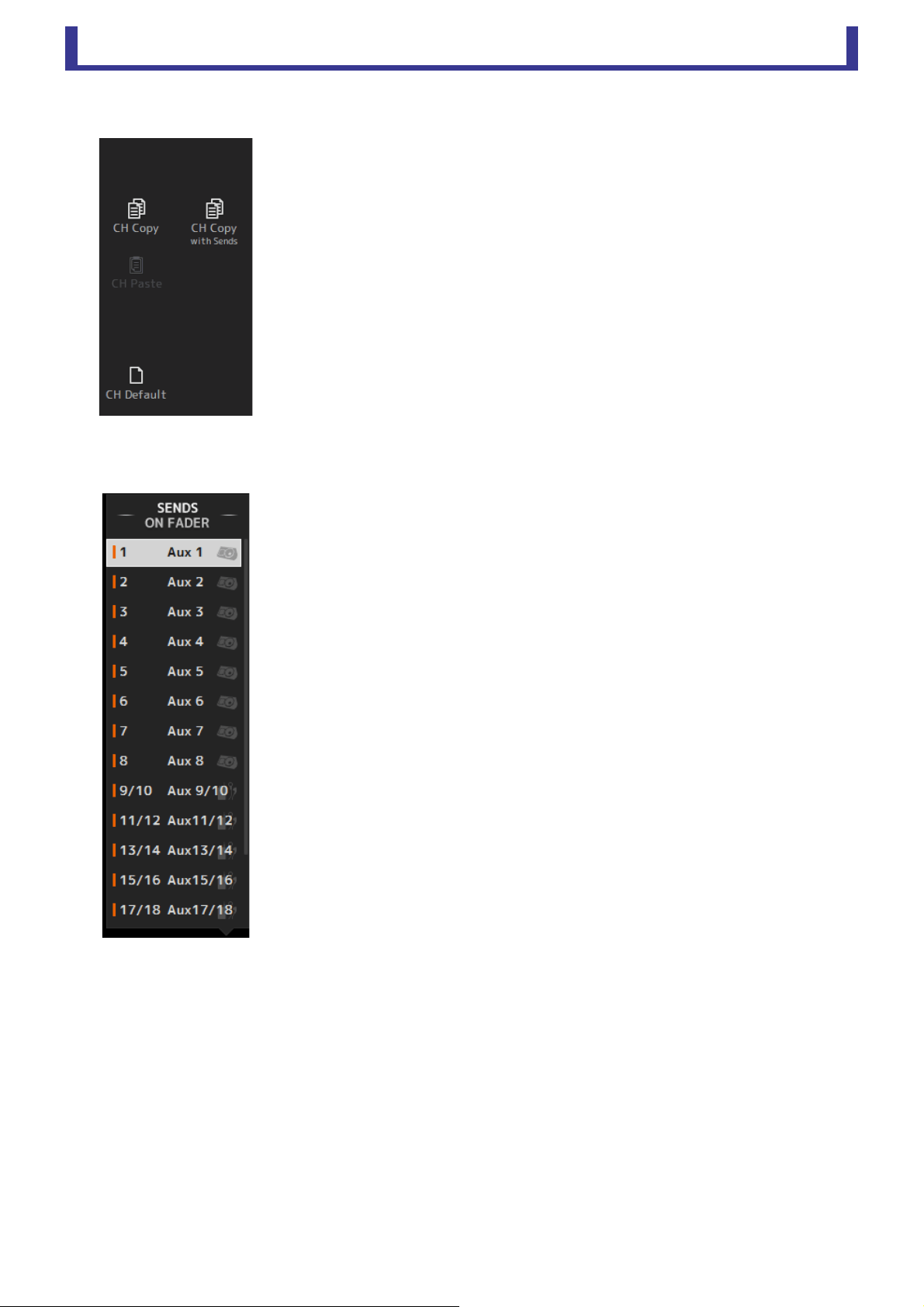
Allows you to use the channel strip area temporarily to adjust SEND LEVEL and SEND ON for
the desired buses.
Click a bus to select it as the active SENDS ON FADER bus. Click a bus again to turn off
SENDS ON FADER for that bus.
You can scroll within this area to display all of the available buses.

Screen areas
User’s Guide
TF Editor
-
11
-
Channel strip area
1 ON button
Turns the channel on and off. This button lights when the channel is turned on. In SENDS ON FADER MODE, this button
controls whether the channel's signal is sent to the selected AUX bus or FX bus.
2 Fader value
Displays the value of the current fader level.
Click to select the fader (it turns pink when selected) and then use the mouse wheel to adjust the level. Click again to specify
a value using your computer's keyboard. Press the [Enter] key to set the value. If you do not press the [Enter] key, the fader
will return to its previous level when you click another part of the channel strip area or adjust the console's fader.
3 Fader
Adjusts the signal level of the channel. In SENDS ON FADER MODE, it adjusts the amount of signal that is sent to the selected
AUX bus or FX bus.
Click to select the fader (it turns pink when selected) and then use the mouse wheel to adjust the level.
In SENDS ON FADER MODE, the fader knob changes color to match the channel color of the destination bus. For channels
that cannot be sent to a bus, such as DCA channels, the fader knob remains white.
4 CUE button
Selects the channel for cue monitoring. This button lights when the cue is turned on.
5 Channel information
Displays the channel's ID, color, and icon. Click this area to select the channel.
6 CLEAR CUE button
Turns off all channel cues.
Master/FX/ST IN strip area
This area is always displayed.
1 Master strip
Controls the stereo bus.
In SENDS ON FADER mode, the send destination is displayed as the master strip.
Additionally, the fader knob changes color to match the channel color of the
corresponding bus.
This strip is unavailable when an FX return channel is selected for SENDS ON FADER
mode.
2 FX RTN/ST IN strip
Control the FX return buses and ST IN channels.
In SENDS ON FADER mode, the fader knob changes color to match the channel color
of the corresponding bus.
䐟
䐠
䐡
䐢
䐣
䐤
䐟䐠

Toolbar
User’s Guide
TF Editor
-
12
-
Toolbar
Allows you to access frequently used features. The toolbar is always displayed, regardless of the current operation.
You can click an icon in the toolbar to display the corresponding screen.
You can close the screen and return to the previous screen by clicking on the icon again or by clicking [X].
1 SCENE screen (page 13)
2 METER screen (page 16)
3 MONITOR screen (page 17)
4 SETUP screen (page 19)
5 Status
The name of the user that is currently logged in (always "Administrator") is displayed with the icon. Additionally, the following
items may be displayed to indicate the corresponding status.
Additionally, the following items may be displayed to indicate the corresponding status.
CUE: The cue is turned on.
OSCILLATOR: The oscillator is turned on.
ձղճմյ
Toolbar
User’s Guide
TF Editor
-
13
-
SCENE screen
Allows you to manage previously saved mixer setups, or "Scenes".
When you recall a Scene, you can exempt certain settings from being replaced by the settings contained in the Scene. This is called
"recall safe".
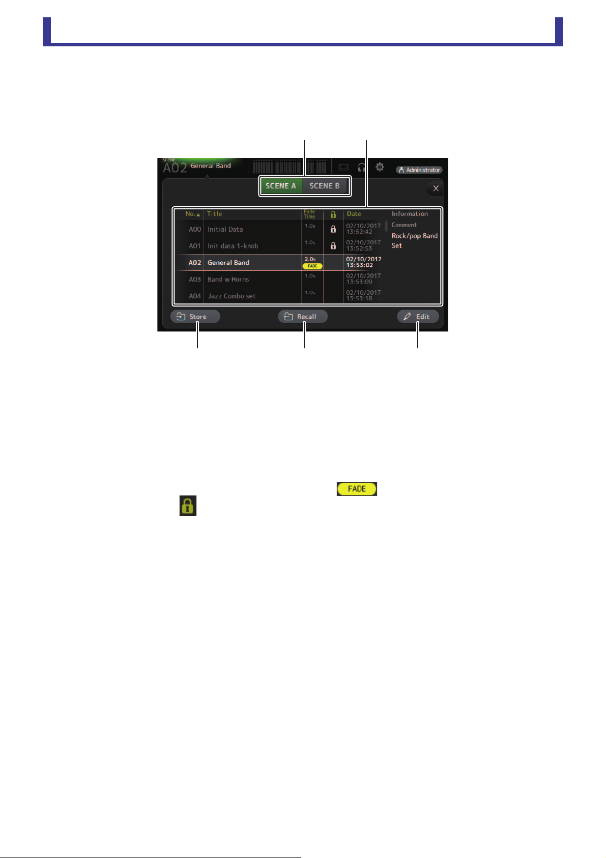
1 Scene list selection button
Allows you to switch between the available Scene lists.
SCENE A: Displays the Scenes stored in Scene list A.
SCENE B: Displays the Scenes stored in Scene list B.
2 Scene list
Displays the Scenes saved in the selected Scene list.
You can click a header in the list to sort the items by that header. (List items cannot be sorted by "Information".)
To select a Scene, simply click it. The selected Scene is highlighted, and can then be saved, recalled, or edited.
A green triangle is displayed in front of the Scene that is currently recalled.
The fade time set for the Scene is shown in the Fade Time column. will be displayed if fade time is enabled.
You can click the area in the column to turn the lock icon on and off. When the icon is displayed, the Scene is write-
protected.
The date on which the Scene was last saved is displayed in the Date column.
3 Store button
Saves the current mixer setup and assigns it to the Scene number selected in the Scene list.
Click this button to edit the title and comment.
4 Recall button
Recalls the Scene that is selected in the Scene list.
5 Edit button
Click this button to edit the title and comment.
䐟䐠
䐡䐢 䐣
Toolbar
User’s Guide
TF Editor
-
14
-
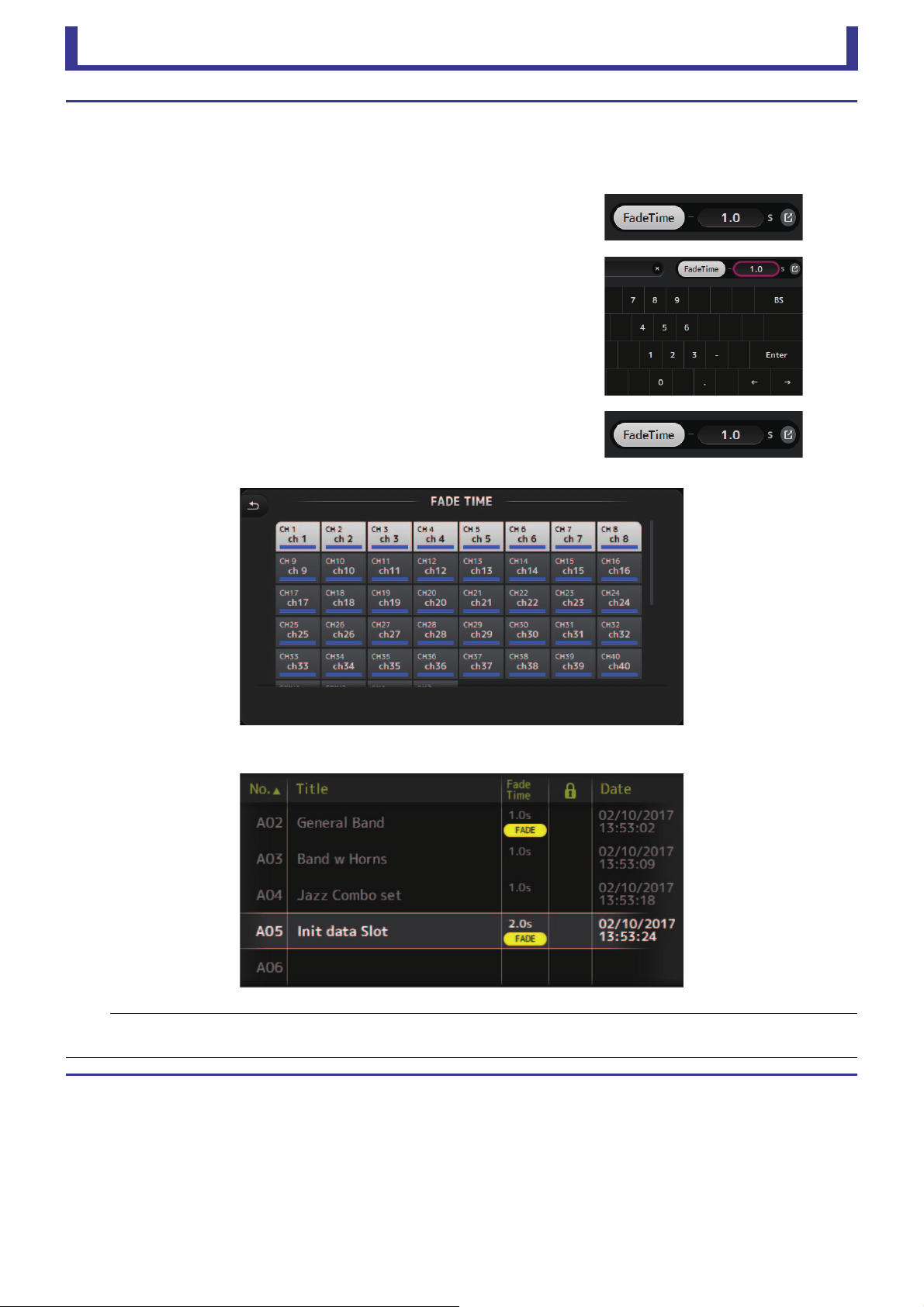
Setting the fade time for a Scene
1. Select the Scene for which the fade time will be set.
2. Click the Edit button.
The screen will display where you can edit the title, comment and fade time (SOFT KEYBOARD screenpage 32).
3. To turn the fade time on, click the FadeTime button. Click the button
once more to turn it off.
4. To set the fade time, click the Fade Time display, and input the setting
using the keyboard.
5. To turn the fade time on and off for each channel, click the button on
the right edge of the screen.
6. Set each channel on or off using the FADE TIME screen.
7. Click the OK button.
The fade times will be set for the Scene.
NOTE
• The fade time for the Scene is a function that operates for the console.
• If you operate a moving fader with TF Editor on the console, the fader effect will stop at that position.
Toolbar
User’s Guide
TF Editor
-
15
-
SCENE screen menu
The following items are displayed in the menu area when the SCENE screen is displayed.
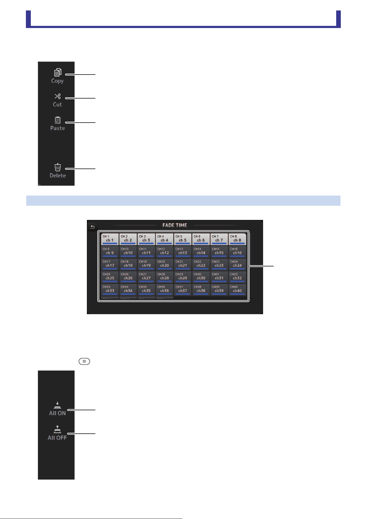
FADE TIME screen
On this screen, you can individually turn the channels on and off for which you want to apply fade time for the Scene.
1 Channel buttons
Use these buttons to individually turn the channels on and off for which you want to apply fade time. If the channel is colored
white, fade time is on.
FADE TIME screen menu
Press the menu key ( ) on the FADE TIME screen to display the menu icons shown below.
1 Copy
Copies the settings of the current Scene.
2 Cut
Cuts the settings from the selected Scene.
3 Paste
Pastes the copied Scene into the current list.
4 Delete
Deletes the selected scene.
1 All ON
Turns on fade time for all channels.
2 All OFF
Turns off fade time for all channels.
ձ
ղ
ճ
մ
ձ
ձ
ղ

Toolbar
User’s Guide
TF Editor
-
16
-
METER screen
Displays the input and output level of all the channels, and allows you to select the metering point (i.e., the point at which the level
is detected) of the level meter.
1 Input metering point selection menu
Determines the input level metering point.
PRE HPF: After the head amp; before the HPF
PRE FADER: Before the fader
POST ON: After the [ON] key
2 Output metering point selection menu
Determines the output level metering point.
PRE EQ: Before the EQ
PRE FADER: Before the fader
POST ON: After the [ON] key
3 Peak Hold button
Turn this button on to hold the peak level for each level meter. Turn this button off to remove the peak level that was being held.
The Peak Hold on/off setting affects both input and output channels.
4 Meters
Display the channel levels.
5 Meter display selection button
Allows you to select how many meters
are displayed.
Three display modes are available.
ձղճ
մ
յ
Toolbar
User’s Guide
TF Editor
-
17
-
MONITOR screen
Allows you to manage cue and monitor signals and to control oscillators.
The CUE/MONITOR screen is used to control the signals that are monitored using headphones and near-field monitors. Here you
can select the sources that will be continuously monitored, and select individual channels for monitoring using the cue feature.
The OSCILLATOR screen is used to configure the oscillator and turn in on and off. The console has a built-in oscillator that can output
a sine wave or pink noise to the desired bus, allowing you to check external devices or test the characteristics of a venue.
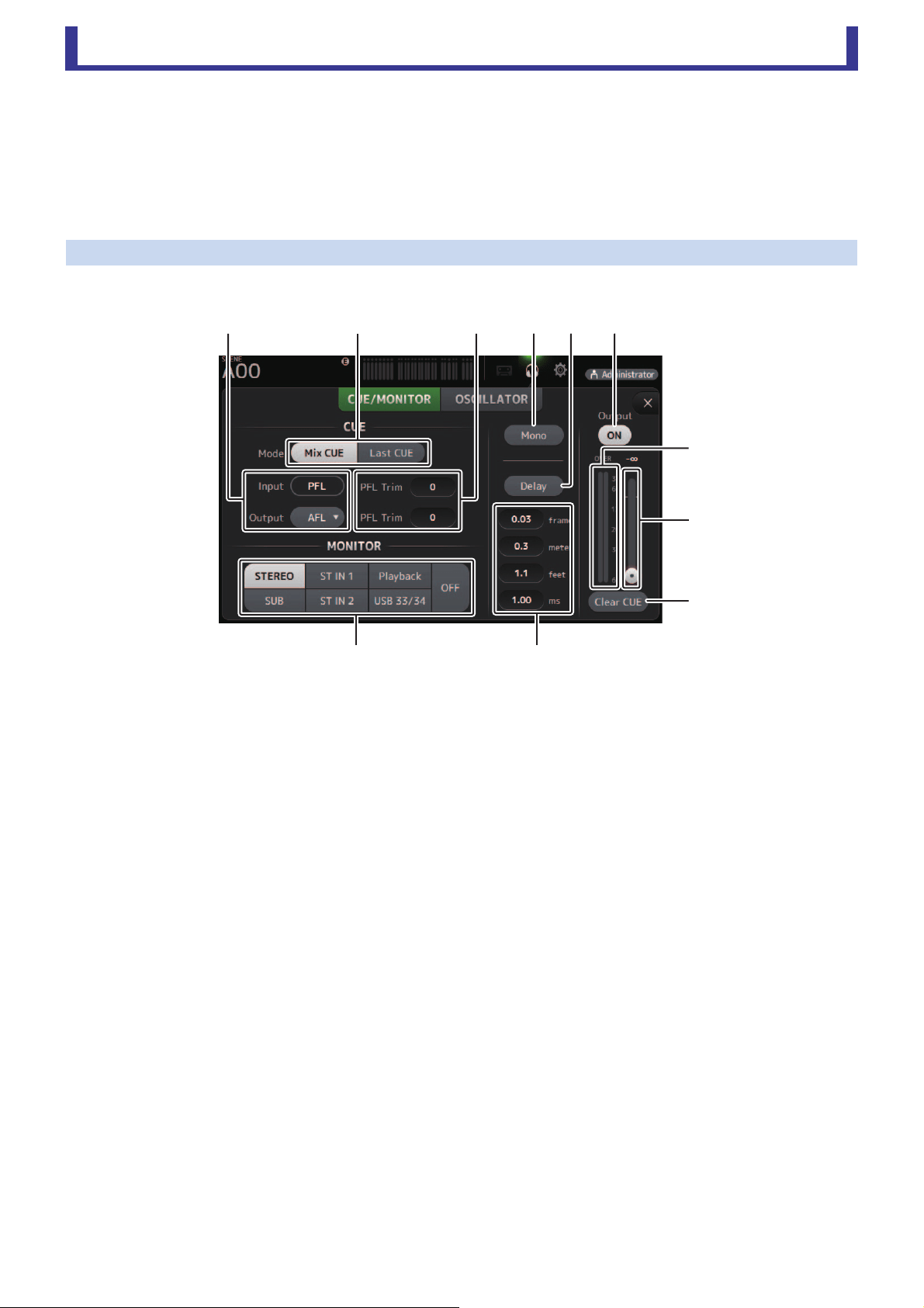
CUE/MONITOR screen
Allows you to monitor certain inputs using headphones or speakers. You can select which sources will be monitored, change the
monitor signal to mono, or add a delay.
1 CUE point selection buttons
Selects the point in the signal path that will be monitored. (Only PFL is available for inputs.)
PFL: Before the fader
AFL: After the fader
2 CUE mode button
Used to select the CUE mode.
Mix CUE: Enables cue for multiple channels.
Last CUE: Enables cue for the last channel selected.
3 PFL Trim setting text box
Adjusts the CUE monitor volume when PFL is selected. This can be set within a range of -30 dB to +20 dB.
Click to display the input screen for each value.
4 Mono button
Allows you to change the monitor signal to mono.
5 Delay button
Delays the monitor signal.
When the cue is turned on, the delay is disabled.
6 Monitor Output button
Turns the monitor output on and off.
The signal is output from the console's [PHONES] jack regardless of this setting.
7 Monitor level meter
Displays the monitor level.
8 Monitor level slider
Adjusts the monitor output level.
The signal is output from the console's [PHONES] jack regardless of this setting.
9 Clear CUE button
Cancels all cue selections.
ղձճմյն
շ
ո
չ
պջ
Toolbar
User’s Guide
TF Editor
-
18
-
0 Delay setting
Allows you to set the unit of measure for the delay: frames, meters, feet or ms (milliseconds).
Click a text box to enter a value.
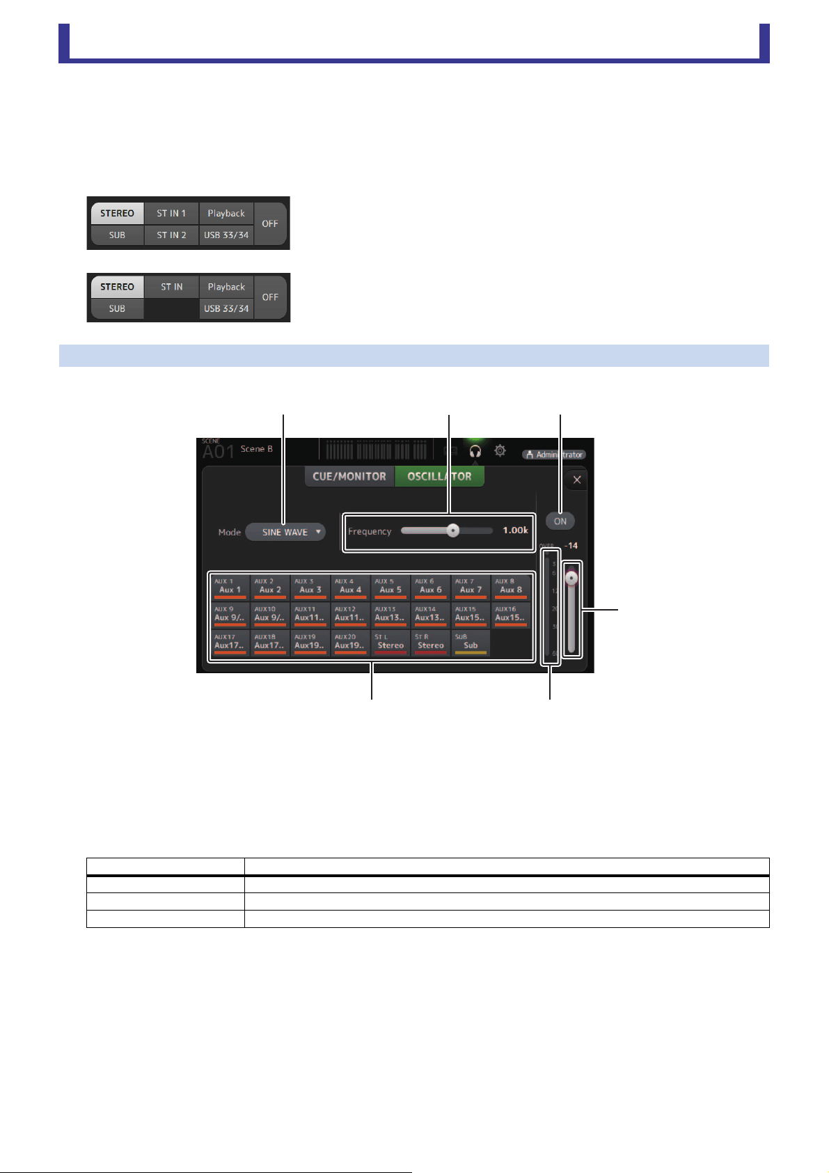
A Monitor source selection buttons
Allow you to select the sources that will be monitored.
TF5/TF3/TF1
TF-RACK
OSCILLATOR screen
Allows you to configure the oscillator.
1 Oscillator mode button
Allows you to select the oscillator mode.
SINE WAVE: A sine wave will be output continuously.
PINK NOISE: Pink noise will be output continuously.
BURST NOISE: Pink noise will be output intermittently.
2 Parameter sliders
Allows you to adjust parameters for the oscillator.
3 Oscillator output button
Turns the oscillator output on and off. When the oscillator is turned on, the oscillator signal is sent to the input channels that
are selected by the oscillator assignment buttons.
4 Oscillator output level slider
Adjusts the oscillator output level.
5 Oscillator output meter
Displays the oscillator output level.
6 Oscillator assignment buttons
Determine which channels the oscillator is sent to. You can click this button to select multiple channels.
Oscillator mode Available parameters
SINE WAVE Frequency
BURST NOISE Width (duration of each noise burst) and Interval (length of silence between noise bursts)
PINK NOISE None
ձղճ
մ
յն

Toolbar
User’s Guide
TF Editor
-
19
-
SETUP screen
Allows you to configure general mixer settings, as well as settings for OMNI OUT and Recall Safe.
1 User Defined Controls (page 24)
Displays the USER DEFINED CONTROLS screen.
2 Custom Fader Bank (page 28)
Displays the CUSTOM FADER BANK screen.
3 Bus Setup (page 20)
Displays the BUS SETUP screen.
4 Recall Safe (page 22)
Displays the RECALL SAFE screen.
5 OMNI OUT (page 21)
Displays the OMNI OUT screen.
6 Mute Group (page 23)
Displays the MUTE GROUP ASSIGN screen.
7 +48V Master button (page 46)
Master button that turns the console's phantom power feature on and off.
When this button is turned off, phantom power will not be supplied to any channels, even if their +48V buttons are turned
on in the INPUT screen.
8 Log (page 29)
Displays the TF Editor LOG screen.
ճյձղ ն
շ
ո
մ
Toolbar
User’s Guide
TF Editor
-
20
-
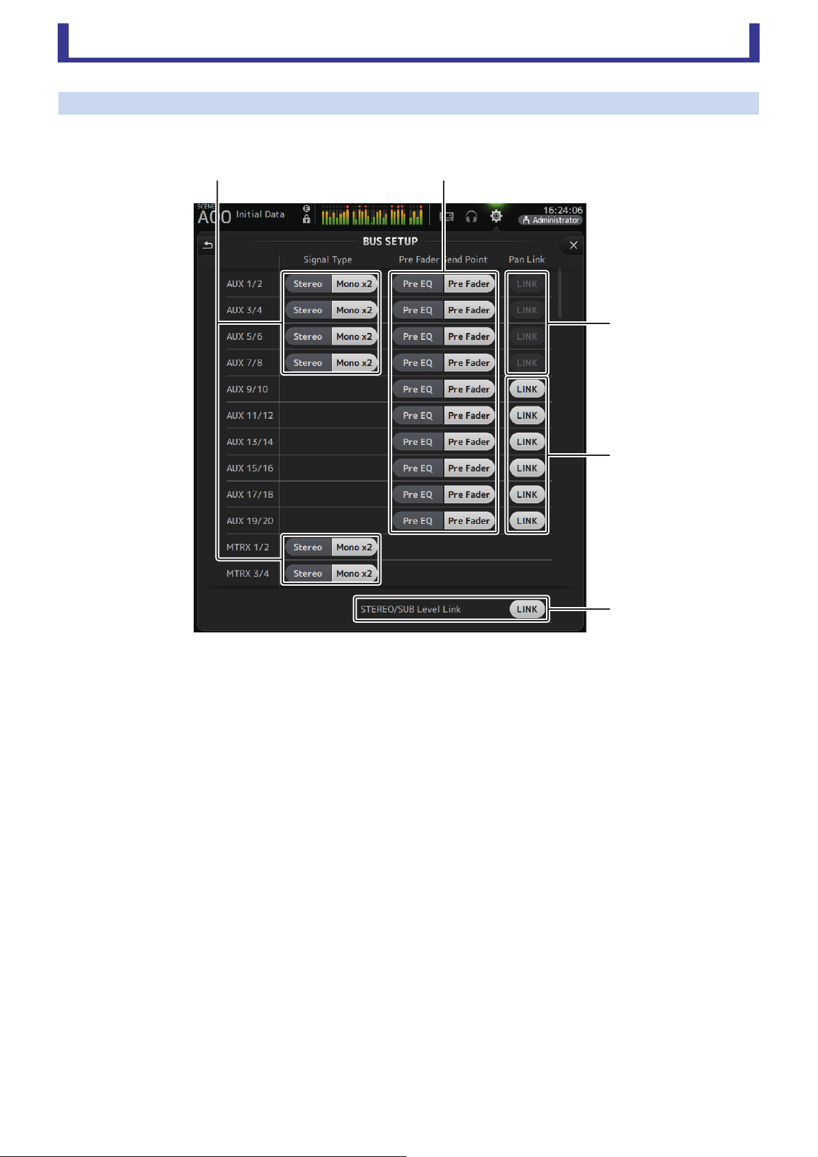
BUS SETUP screen
Allows you to configure bus settings. You can change basic settings such as stereo/mono, Pan Link, etc.
These settings are included when saving a Scene.
1 AUX1/2–AUX7/8 signal type selection button
MATRIX1/2–MATRIX3/4 signal type selection button
Determines how each pair of buses is processed. You can set each pair to be either Stereo (an odd and even numbered bus
are paired and main parameters are shared between the two) or Mono x2 (two independent mono channels).
2 Pre Fader Send Point selection button
Selects the send point when Pre is on, for the send from the input channel to the AUX bus.
Pre EQ: directly before EQ
Pre Fader: directly before fader
3 AUX 1/2–AUX 7/8 Pan Link buttons
Turns pan link on and off for AUX 1/2–AUX 7/8.
These buttons are only displayed if the Signal Type of the corresponding bus is set to Stereo.
When these buttons are turned on, the pan setting of signals sent from input channels to the corresponding two buses will
link with the Stereo bus pan setting.
4 AUX 9/10–AUX 19/20 Pan Link buttons
Turns pan link on and off for AUX 9/10–AUX 19/20.
5 STEREO/SUB Level Link
Determines whether the faders for the STEREO bus and the SUB bus are linked.
ճ
մ
յ
ձղ
Toolbar
User’s Guide
TF Editor
-
21
-
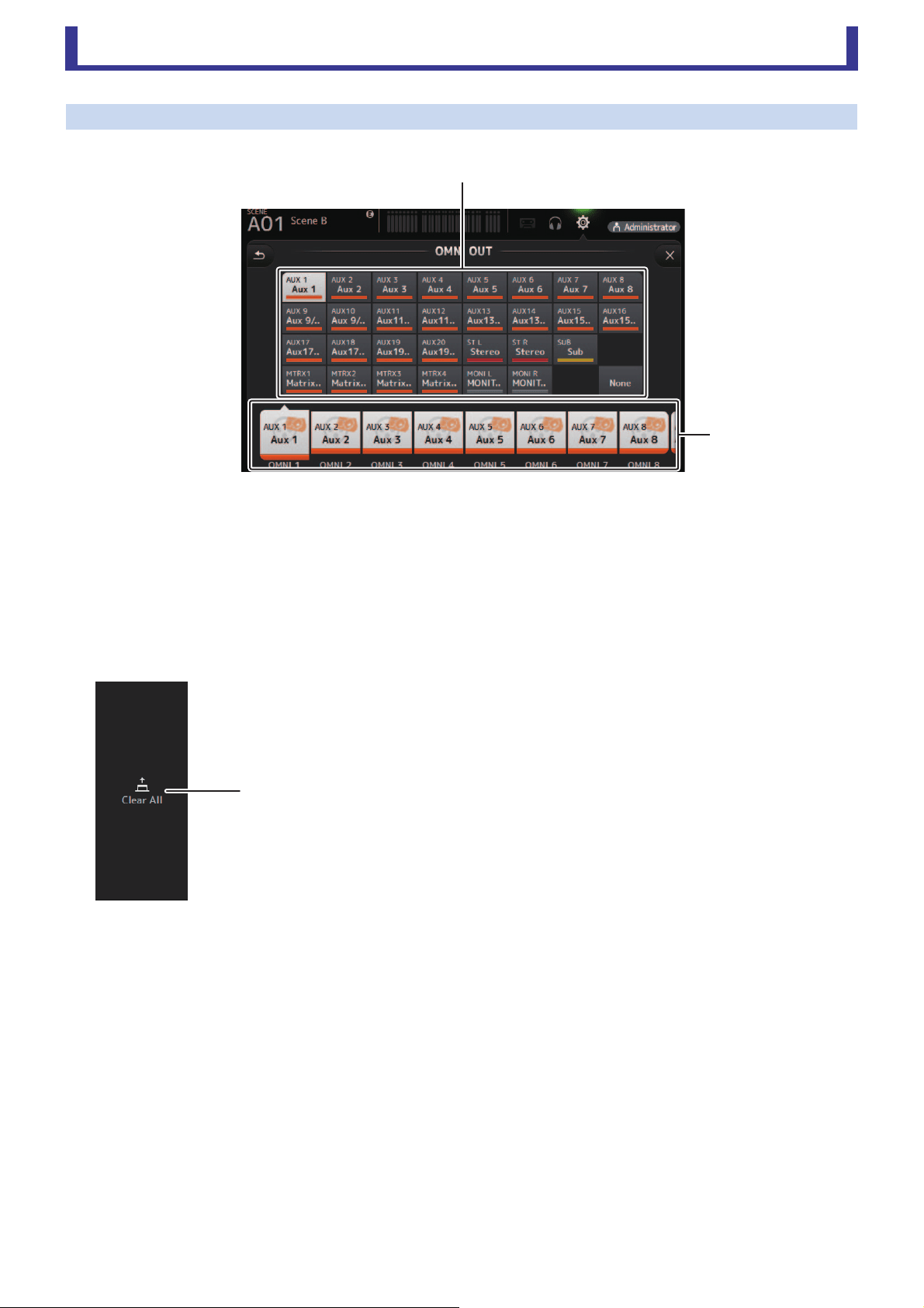
OMNI OUT screen
Allows you to configure the output channels that are sent to the OMNI OUT jacks.
1 OMNI OUT1–16 buttons
Allows you to select which OMNI OUT jack will be configured.
The name of the channel currently assigned to each OMNI OUT jack is also displayed in the buttons.
2 Output channel buttons
Determines which output channel or monitor output will be assigned to the OMNI OUT jack you selected for 1.
If you select None, nothing will be output to the corresponding OMNI OUT jack.
OMNI OUT screen menu
The following items are displayed in the menu area when the OMNI OUT screen is displayed.
1 Clear All
Clears all assignments for each OMNI OUT jack (all will be set to None).
ղ
ձ
ձ
Toolbar
User’s Guide
TF Editor
-
22
-
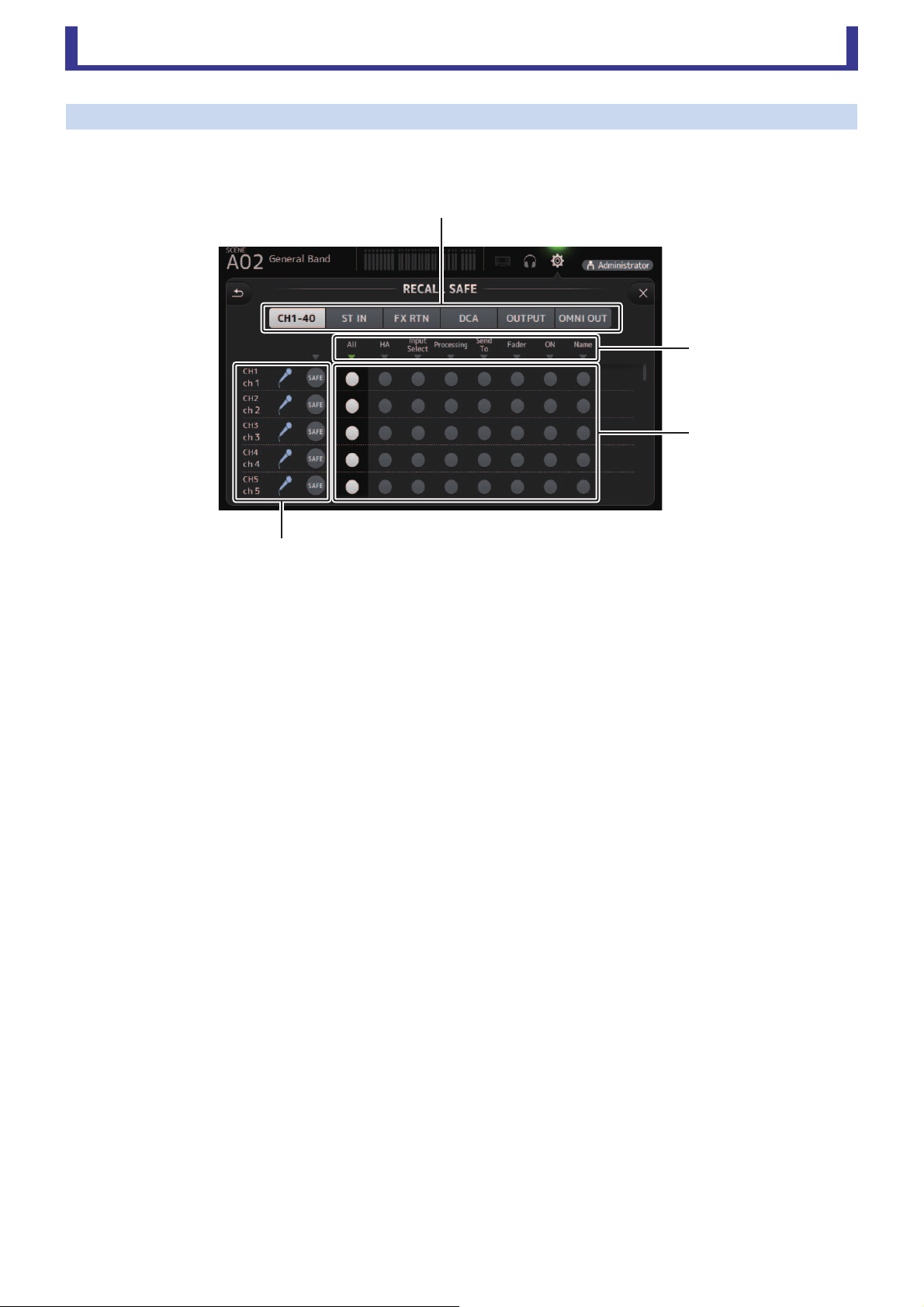
RECALL SAFE screen
Allows you to configure which items are recalled and which items are not (i.e., recall safe) when recalling Scenes and Presets.
"Recall safe" allows you to select certain parameters, channels, DCA groups, etc. whose settings will not be replaced when recalling
a Preset or Scene.
1 Channel selection buttons
Allows you to select which types of channels will be configured.
When you select a channel type, the different parameters that can be configured as recall safe are displayed.
2 Parameter names
Click to turn recall safe on and off for the corresponding parameters for all channels.
When recall safe is turned on for a parameter on all channels, the mark under the parameter name is displayed in green.
If turned off for a parameter on all channels, it is displayed in gray. Finally, if recall safe is turned on for a parameter but not
for all channels, the mark under the parameter name is displayed in blue.
3 Recall safe on/off buttons
Turns recall safe on and off for the corresponding parameter. When turned on, the corresponding parameter is recall safe,
i.e., its setting will not be changed when a Preset or Scene is recalled.
For OMNI OUT assignments, recall safe can be turned on and off for all OMNI OUT jacks, but not for individual jacks.
4 Channel information
Displays the channel ID, name, and icon.
Click the SAFE button to turn recall safe on and off for the corresponding channel.
When turned on, parameters whose recall safe on/off buttons are in the "on" position will not be recalled.
ձ
ղ
ճ
մ
Toolbar
User’s Guide
TF Editor
-
23
-
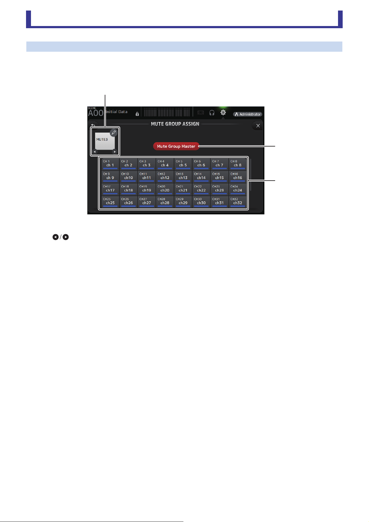
MUTE GROUP ASSIGN screen
Allows you to configure the mute group and mute safe for each input channel.
INPUT (MUTE GROUP1) and FX (MUTE GROUP2) are preassigned for the mute groups. Input channels can be assigned for the
other mute groups (MUTE GROUP3 through MUTE GROUP6).
Use the mute safes to exclude a channel from the mute group operations. ST IN1 and ST IN2 are assigned as default settings.
1 Mute group name
Click the pencil icon at the top right to display the edit screen.
Click to switch between information for different mute groups.
2 Mute Group Master button
Switches the currently displayed mute group on and off. When this is off, the relevant mute group will be disabled.
3 MUTE GROUP ASSIGN buttons
Use these buttons to select the input channels that will be assigned to the currently displayed mute group.
ձ
ղ
ճ
Toolbar
User’s Guide
TF Editor
-
24
-
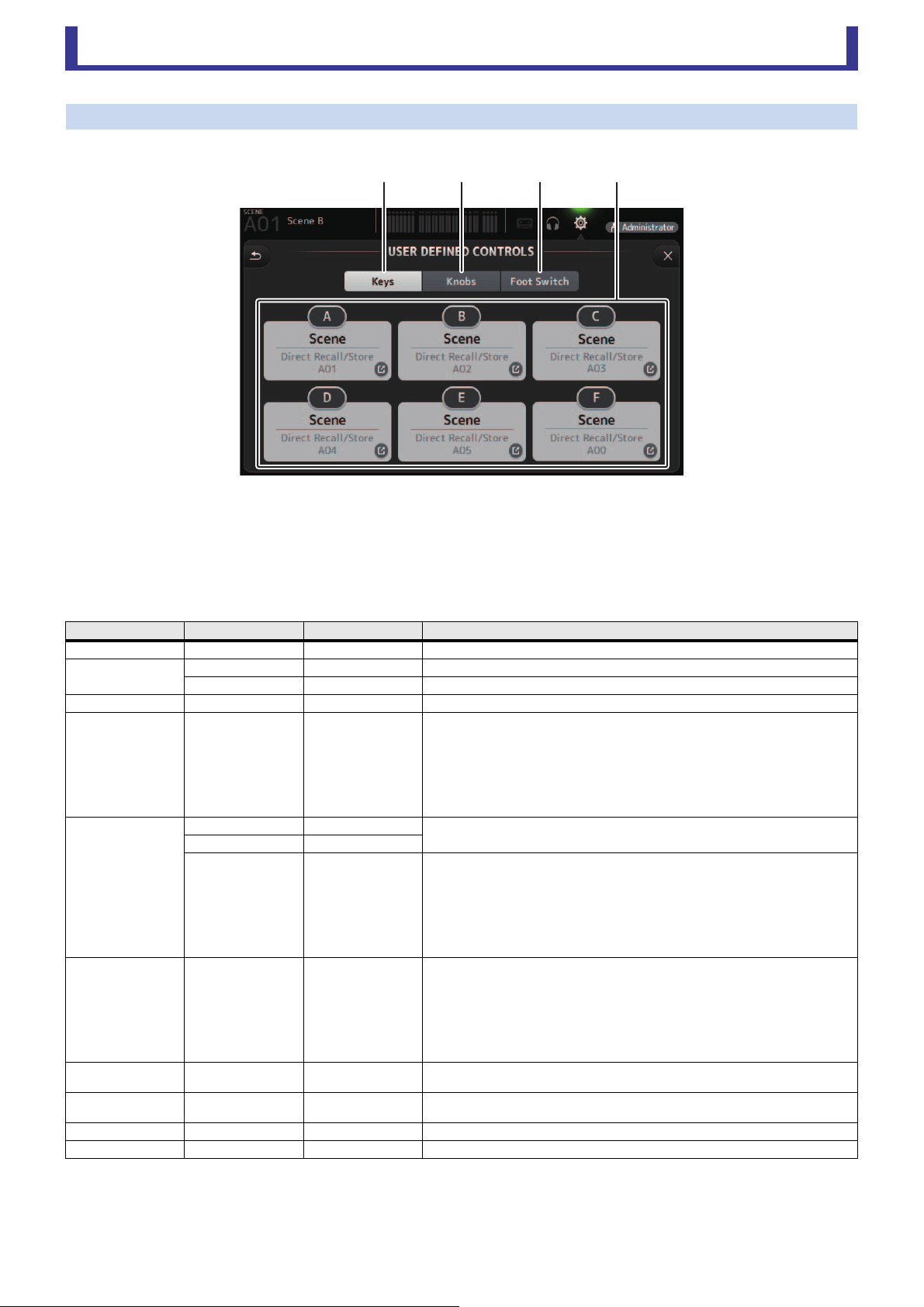
USER DEFINED CONTROLS screen
This screen allows you to assign features to the [USER DEFINED KEYS], [USER DEFINED KNOBS], and to the footswitch.
1 Keys button
Allows you to assign features to the [USER DEFINED KEYS] on the console's top panel.
2 Key setup buttons (A–F)
Click the desired button to display the screen that allows you to assign features to the corresponding USER DEFINED KEY.
Features that can be assigned to USER DEFINED KEYS
FUNCTION PARAMETER 1 PARAMETER 2
Description
No Assign No feature is assigned.
Automixer
Bypass Group a, Group b Bypasses the group assigned to PARAMETER 2.
Specific CH CH 1–8 Turns the Automixer on and off for the channel assigned to PARAMETER 2.
Brightness Bank Change Switches between the brightness banks.
CH ON Specific CH
CH 1–40,
ST IN 1, ST IN 2,
FX 1, FX 2,
DCA 1–8,
AUX 1–8,
AUX 9/10–19/20,
STEREO, SUB,
MATRIX1–4
Turns the channel assigned to PARAMETER 2 on and off.
CH Select
Inc
Select channels in order of the direction selected for PARAMETER 1.
Dec
Specific CH
CH 1–40,
ST IN 1L–ST IN 2R,
FX 1L–FX 2R,
AUX 1–8,
AUX 9–20,
STEREO L, STEREO R,
SUB,
MATRIX1–4
Selects the channel assigned to PARAMETER 2.
CUE Specific CH
CH 1–40,
ST IN 1, ST IN 2,
FX 1, FX 2,
DCA 1–8,
AUX 1–8,
AUX 9/10–19/20,
STEREO, SUB,
MATRIX1–4
Turns the cue on and off for the channel assigned to PARAMETER 2.
Effect Bypass
FX 1, FX 2,
INS FX 1–6
Bypasses the effect assigned to PARAMETER 2.
EQ Band Select
HPF, LPF, L ow, Low- Mi d,
High-Mid, High
Selects the band assigned to PARAMETER 2.
Help Displays help information.
Meter Peak Hold ON Turns the peak hold on and off.
ձճյղ
Toolbar
User’s Guide
TF Editor
-
25
-
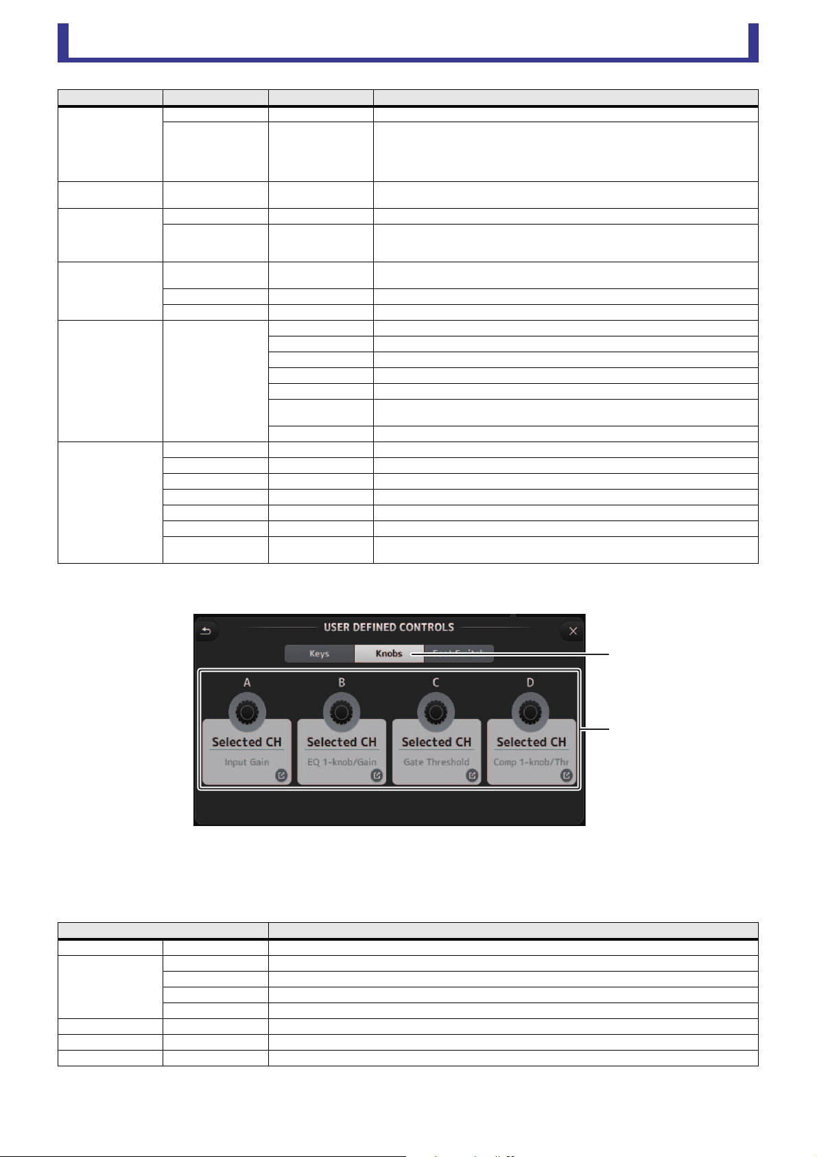
3 Knobs button
Allows you to assign features to the [USER DEFINED KNOBS] on the console's top panel.
4 Knob setup buttons
Click the desired button to display the screen that allows you to assign features to the corresponding USER DEFINED KNOB.
Features that can be assigned to USER DEFINED KNOBS
Monitor
Output Turns the monitor out on and off.
Source Select
STEREO, SUB,
ST IN 1, ST IN 2,
STIN (TF-RACK),
USB 33/34,
Playback
Selects the monitor source assigned to PARAMETER 2.
Mute Master
MUTE GROUP 3–
MUTE GROUP 6
Turns the mute on and off for the MUTE GROUP assigned to PARAMETER 1.
Oscillator
Oscillator On Turns the oscillator on and off.
Specific CH
AUX 1–20,
STEREO L, R,
SUB
Turns the oscillator sent to the channel assigned to PARAMETER 2 on and off.
Page Change
Bookmark
Click and hold for more than 2 seconds to bookmark the current screen. Click and hold
for less than two seconds to display the bookmarked screen.
Bookmark with “SEL” The selected channel is saved with the bookmark. Same as above.
Close Popup Closes the popup screen.
Recorder Transport
Play/Pause Same as the Play/Pause button on the RECORDER screen.
Stop Same as the Stop button on the RECORDER screen.
Next Same as the Next button on the RECORDER screen.
Previous Same as the Previous button on the RECORDER screen.
Rec Same as the Rec button on the RECORDER screen.
Auto Rec
Recording stops and the file is saved, and then recording resumes immediately as a new
file.
Rec & Start Recording starts immediately without entering record-ready mode.
SCENE
Inc Selects the next numbered Scene.
Dec Selects the previous numbered Scene.
Store Stores the current settings to selected Scene number.
Recall Recalls the selected numbered Scene.
Inc Recall Recalls the next numbered Scene.
Dec Recall Recalls the previous numbered Scene.
Direct Recall/Store
No. A00–99,
No. B00–99
Recalls the Scene number assigned to PARAMETER 2. Click and hold for more than two
seconds to store the current settings to that Scene number.
Features Description
No Assign No feature is assigned.
Brightness
CH Name Adjusts the brightness of channel name. (TF5/TF3/TF1 only)
CH Color Adjusts the brightness of the channel color indicator. (TF5/TF3/TF1 only)
Screen Adjusts the brightness of the touch screen.
Panel Adjusts the brightness of the panel LEDs.
CH Level Specific CH Adjusts the level of the channel assigned to PARAMETER 2.
CH Select Inc/Dec Selects the channel.
Monitor Level Adjusts monitor level.
FUNCTION PARAMETER 1 PARAMETER 2
Description
ճ
մ
Knob setup buttons
Toolbar
User’s Guide
TF Editor
-
26
-
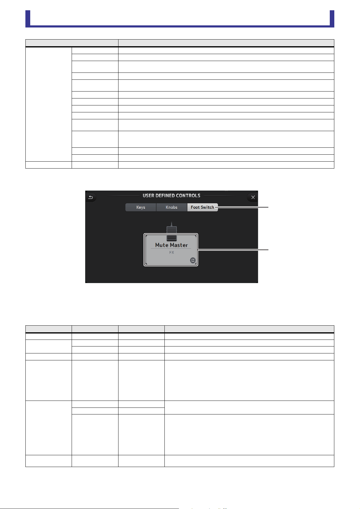
5 Foot Switch button
Allows you to assign features to the console's footswitch.
6 Foot Switch setup button
Displays the features that can be assigned to the footswitch.
Features that can be assigned to the footswitch
Selected CH
Automixer Weight AUTOMIXER Weight operations for the selected channel
CH Level Adjusts the level of the selected channel.
Comp 1-knob/Thr
Adjusts 1-knob or threshold for the selected channel's COMP.
When 1-knob COMP is turned on, adjusts 1-knob; when 1-knob COMP is turned off, adjusts threshold.
Digital Gain Adjusts the DIGITAL GAIN of the selected channel.
EQ 1-knob/Gain
Adjusts 1-knob or gain for the selected channel's EQ.
When 1-knob EQ is turned on, adjusts 1-knob; when 1-knob EQ is turned off, adjusts gain.
EQ Band Select Selects the band for the selected channel.
EQ Frequency Adjusts EQ frequency for the selected channel.
EQ Q Adjusts EQ Q for the selected channel.
Gate Threshold Adjusts gate threshold for the selected channel.
HPF
Adjusts HPF for the selected channel.
Turn the knob to adjust the frequency.
Input Gain
Adjusts analog gain or digital gain for the selected channel.
When the channel's input is an analog source, adjusts analog gain.
When the channel's input is a digital source (i.e., USB, iPad, or STIN), adjusts digital gain.
Send Level Adjusts the send level to the bus selected for PARAMETER2 (FX, AUX, SUB) for the selected channel.
Pan Adjusts pan or balance for the selected channel.
RTA Offset Adjusts RTA Offset.
FUNCTION PARAMETER 1 PARAMETER 2
Description
No Assign No feature is assigned.
Automixer
Bypass Group a, Group b Bypasses the group assigned to PARAMETER 2.
Specific CH CH 1–4 Turns the Automixer on and off for the channel assigned to PARAMETER 2.
Brightness Bank Change Switches between the brightness banks.
CH ON Specific CH
CH 1–40,
ST IN 1, ST IN 2,
FX 1, FX 2,
DCA 1–8,
AUX 1–8,
AUX 9/10–19/20,
STEREO, SUB,
MATRIX1–4
Turns the channel assigned to PARAMETER 2 on and off.
CH Select
Inc
Select channels in order of the direction selected for PARAMETER 1.
Dec
Specific CH
CH 1–40,
ST IN 1L–ST IN 2R,
FX 1L–FX 2R,
AUX 1–8,
AUX 9–20,
STEREO L, STEREO R,
SUB,
MATRIX1–4
Selects the channel assigned to PARAMETER 2.
Clear Cue Clear Cue
Clears all cue selections.
Same as the CLEAR CUE key on the top panel.
Features Description
յ
ն
Foot Switch setup button

Toolbar
User’s Guide
TF Editor
-
27
-
Feature assignment screen
When you select a Function, the items available for Parameter 1 are displayed. Likewise, when you select an item for Parameter 1,
the items available for Parameter 2 are displayed. Some Functions may not have items available for Parameter 1; some Parameter
1 items may not have items available for Parameter 2.
CUE Specific CH
CH 1–40,
ST IN 1, ST IN 2,
FX 1, FX 2,
DCA 1–8,
AUX 1–8,
AUX 9/10–19/20,
STEREO, SUB,
MATRIX1–4
Turns the cue on and off for the channel assigned to PARAMETER 2.
Effect Bypass
FX 1, FX 2,
INS FX 1–6
Bypasses the effect assigned to PARAMETER 2.
EQ Band Select
HPF, LPF, L ow, Low- Mi d,
High-Mid, High
Selects the band assigned to PARAMETER 2.
Help Displays help information.
Meter Peak Hold ON Turns the peak hold on and off.
Monitor
Output Turns the monitor out on and off.
Source Select
STEREO, SUB,
ST IN 1, ST IN 2,
STIN (TF-RACK),
USB 33/34,
Playback
Selects the monitor source assigned to PARAMETER 2.
Mute Master
MUTE 1 (INPUT),
MUTE 2 (FX),
MUTE GROUP 3–
MUTE GROUP 6
Turns the mute on and off for the channel or the MUTE GROUP assigned to PARAMETER
1.
Oscillator
Oscillator On Turns the oscillator on and off.
Specific CH
AUX 1–20,
STEREO L, R,
SUB
Turns the oscillator sent to the channel assigned to PARAMETER 2 on and off.
Page Change
Bookmark
Click and hold for more than 2 seconds to bookmark the current screen. Click and hold
for less than two seconds to display the bookmarked screen.
Bookmark with “SEL” The selected channel is saved with the bookmark. Same as above.
Close Popup Closes the popup screen.
Recorder Transport
Play/Pause Same as the Play/Pause button on the RECORDER screen.
Stop Same as the Stop button on the RECORDER screen.
Next Same as the Next button on the RECORDER screen.
Previous Same as the Previous button on the RECORDER screen.
Rec Same as the Rec button on the RECORDER screen.
Auto Rec
Recording stops and the file is saved, and then recording resumes immediately as a new
file.
Rec & Start Recording starts immediately without entering record-ready mode.
SCENE
Inc Selects the next numbered Scene.
Dec Selects the previous numbered Scene.
Store Stores the current settings to selected Scene number.
Recall Recalls the selected numbered Scene.
Inc Recall Recalls the next numbered Scene.
Dec Recall Recalls the previous numbered Scene.
Direct Recall/Store
No. A00–99,
No. B00–99
Recalls the Scene number assigned to PARAMETER 2. Click and hold for more than two
seconds to store the current settings to that Scene number.
TAP TEMPO Same as the TAP key on the top panel.
FUNCTION PARAMETER 1 PARAMETER 2
Description
Toolbar
User’s Guide
TF Editor
-
28
-
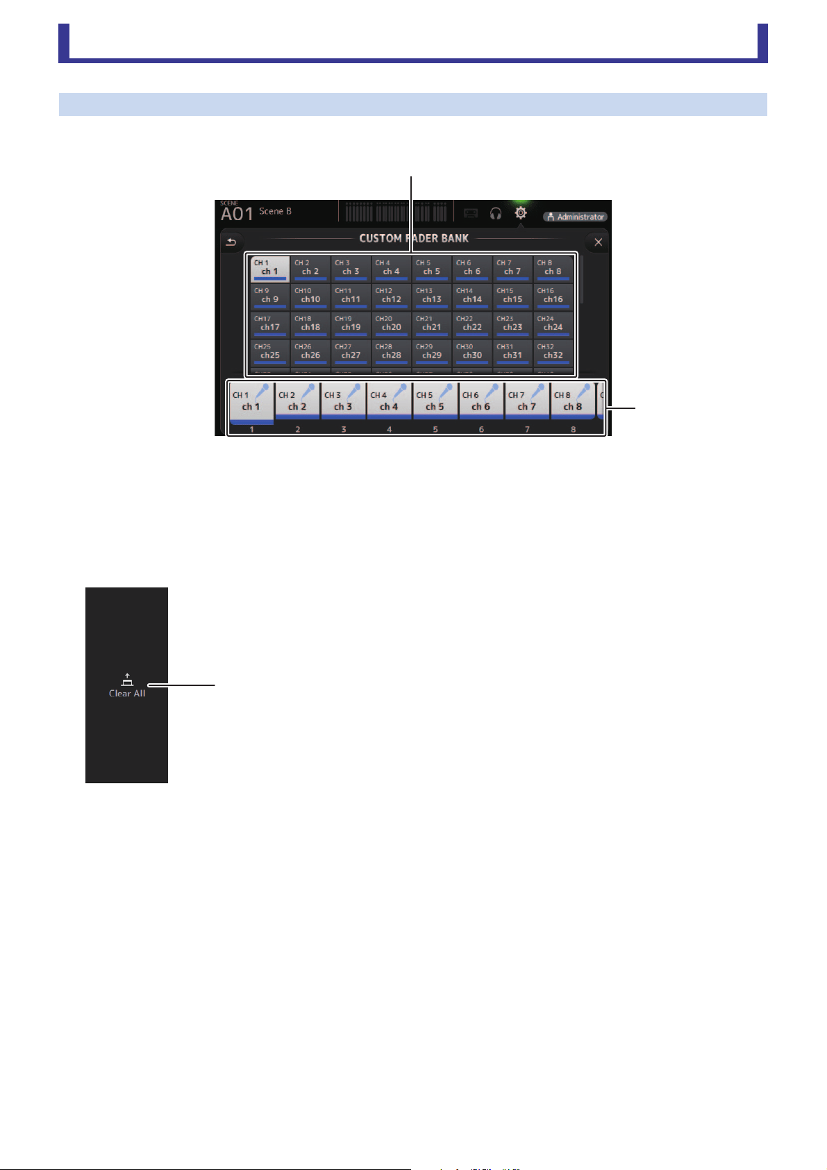
CUSTOM FADER BANK screen
The custom fader bank allows you to choose different channels, regardless of type (input channels, AUX, MATRIX, DCA groups,
etc.), and group them into a bank of faders.
1 Fader buttons
Allow you to select which fader will be configured.
2 Channel buttons
Determines which channel will be assigned to the fader you selected for 1. If you select None, nothing will be assigning to
the corresponding fader.
CUSTOM FADER BANK screen menu
The following items are displayed in the menu area when the CUSTOM FADER BANK screen
is displayed.
1 Clear All
Clears all assignments for each fader (all will be set to None).
ղ
ձ
ձ
Toolbar
User’s Guide
TF Editor
-
29
-
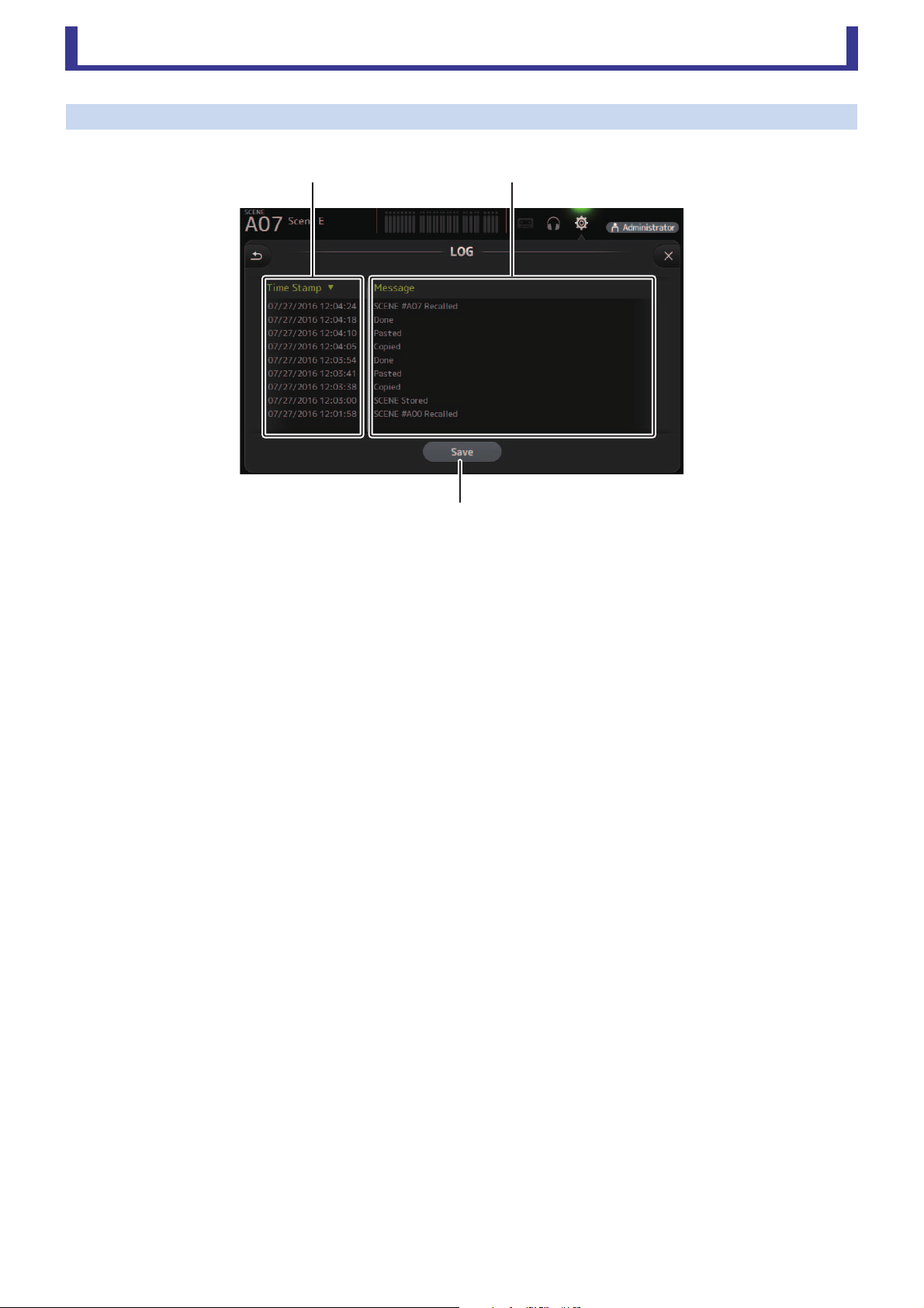
LOG screen
When messages are displayed while using TF Editor, they are logged by date and time and can be viewed later on this screen.
1 Time Stamp field
Displays the date and time of each message.
You can click the header to sort messages by date and time.
2 Message field
Displays messages.
You can click the header to sort messages alphabetically by message.
3 Save button
Saves the log.
ձղ
ճ
Main display area
User’s Guide
TF Editor
-
30
-
Main display area
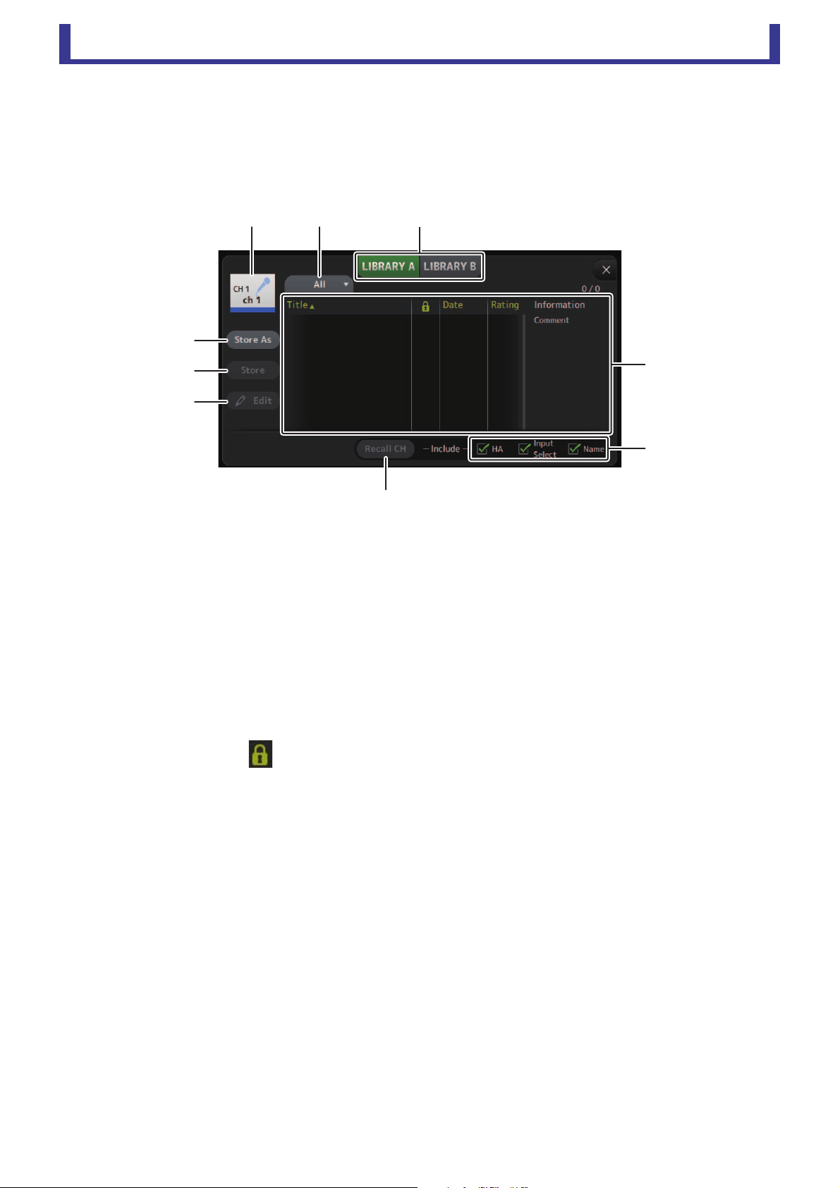
LIBRARY screen
Displayed when you click the LIBRARY button in the HOME/LIBRARY area.
Allows you to recall saved Presets.
A preset is a collection of settings that are customized for a certain type of input, instrument, etc. By recalling a Preset, you can set
up a channel quickly and easily according to the type of input, and then fine-tune the settings to your specific needs. You can even
save your own Presets.
1 Channel name
Displays the name of the channel.
2 Category selection button
Allows you to select a category. Presets that match the selected category are displayed in the Library list.
3 Library selection button
Allows you to switch between the Libraries.
LIBRARY A: Displays the Presets stored in LIBRARY A.
LIBRARY B: Displays the Presets stored in LIBRARY B.
4 List
Displays the Presets.
You can click a header in the list to sort the items by that header. (List items cannot be sorted by "Information".)
To select a Preset, simply click it. The selected Preset is highlighted, and can then be saved, recalled, or edited.
You can click the area in the column to turn the lock icon on and off. When the icon is displayed, the Scene is write-
protected.
The date on which the Scene was last saved is displayed in the Date column.
5 Recall on/off checkboxes
Allow you to determine which parameters will be recalled (checkbox on) and not be recalled (checkbox off).
The parameters that will be recalled vary depending on the type of Preset.
Input channels
HA: Analog/digital gain setting, phantom power on/off, fader setting
Input Select: Input source settings
Name: Channel name, icon, and color
AUX 1–8, STEREO channels
GEQ: GEQ settings
Name: Channel name, icon, and color
FX RTN, AUX9/10–AUX19/20 channels
FX: Effect settings
Name: Channel name, icon, and color
SUB, MATRIX1–MATRIX4 channels
Name: Channel name, icon, and color
6 Recall CH button
Recalls a Preset to the selected channel.
ձղ ճ
մ
յ
ն
շ
ո
չ
Main display area
User’s Guide
TF Editor
-
31
-
7 Edit button
Click this button to edit the title and comment.
8 Store button
Saves the settings for the current channel as a Preset. The settings will overwrite the Preset selected in the Library list.
9 Store As button
Saves the settings for the current channel as a new Preset.
Click this button to enter a name for the Preset.
Displaying the Library screen from a configuration screen
When you display the Library screen from a configuration screen, one of the following buttons is added to the Library screen,
depending on the configuration screen you were using.
Recall EQ button
Displayed when you enter the Library from the EQ screen, and recalls EQ/HPF settings only.
Recall Gate button
Displayed when you enter the Library from the GATE screen, and recalls GATE settings only.
Recall COMP button
Displayed when you enter the Library from the COMP screen, and recalls COMP settings only.
Recall FX button
Displayed when you enter the Library from the FX screen, and recalls FX settings only.
Recall GEQ button
Displayed when you enter the Library from the GEQ screen, and recalls GEQ settings only.
Importing and exporting Presets
You can back up individual Presets to your computer by dragging them from the Preset list in the LIBRARY screen and dropping
them in a folder on your computer. Click and hold the preset you want to export, and then drag and drop.
The Preset will be saved on your computer as a TFP file.
You can add the TPF file to the Library by dragging the file from a folder on your computer and dropping it into TF Editor.
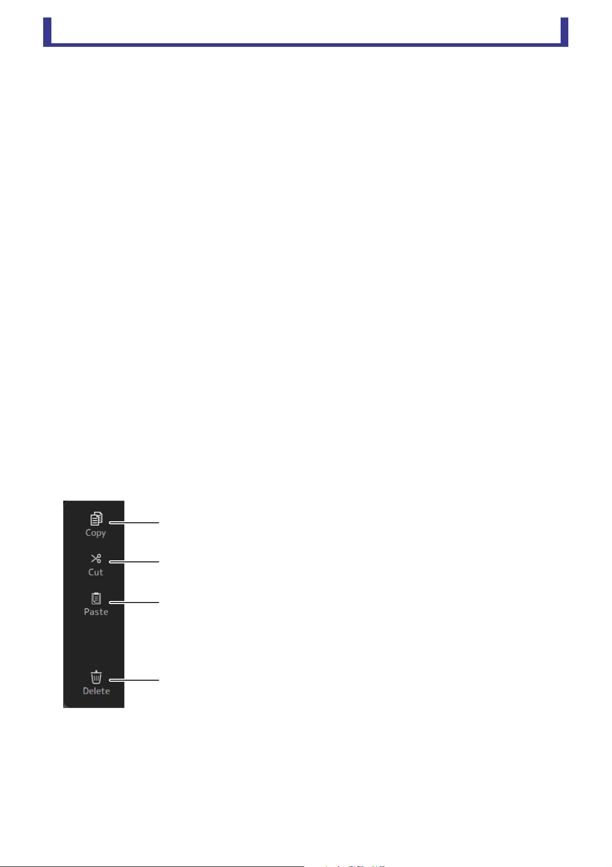
LIBRARY screen menu
The following items are displayed in the menu area when the LIBRARY screen is displayed.
1 Copy
Copies the selected Preset.
2 Cut
Cuts the selected Preset.
3 Paste
Pastes settings from the copied Preset and applies them to the selected Preset.
4 Delete
Deletes the selected Preset.
ձ
ղ
ճ
մ
Main display area
User’s Guide
TF Editor
-
32
-
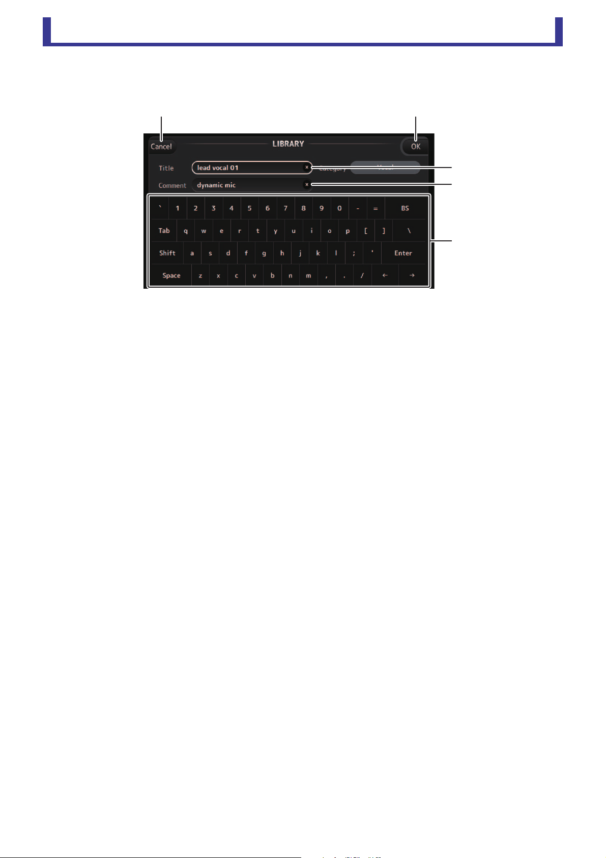
SOFT KEYBOARD screen
Allows you to edit titles and comments. This screen varies depending on the operation you are performing.
1 Cancel button
Discards any changes you made and returns to the previous screen.
2 OK button
Saves the changes you made.
3 Title field
4 Comment field
Enter text here.
5 Keyboard
Click to enter the desired text.
You can use the on-screen keyboard or your computer's keyboard to enter text.
䐡
䐢
䐣
䐟䐠
Main display area
User’s Guide
TF Editor
-
33
-
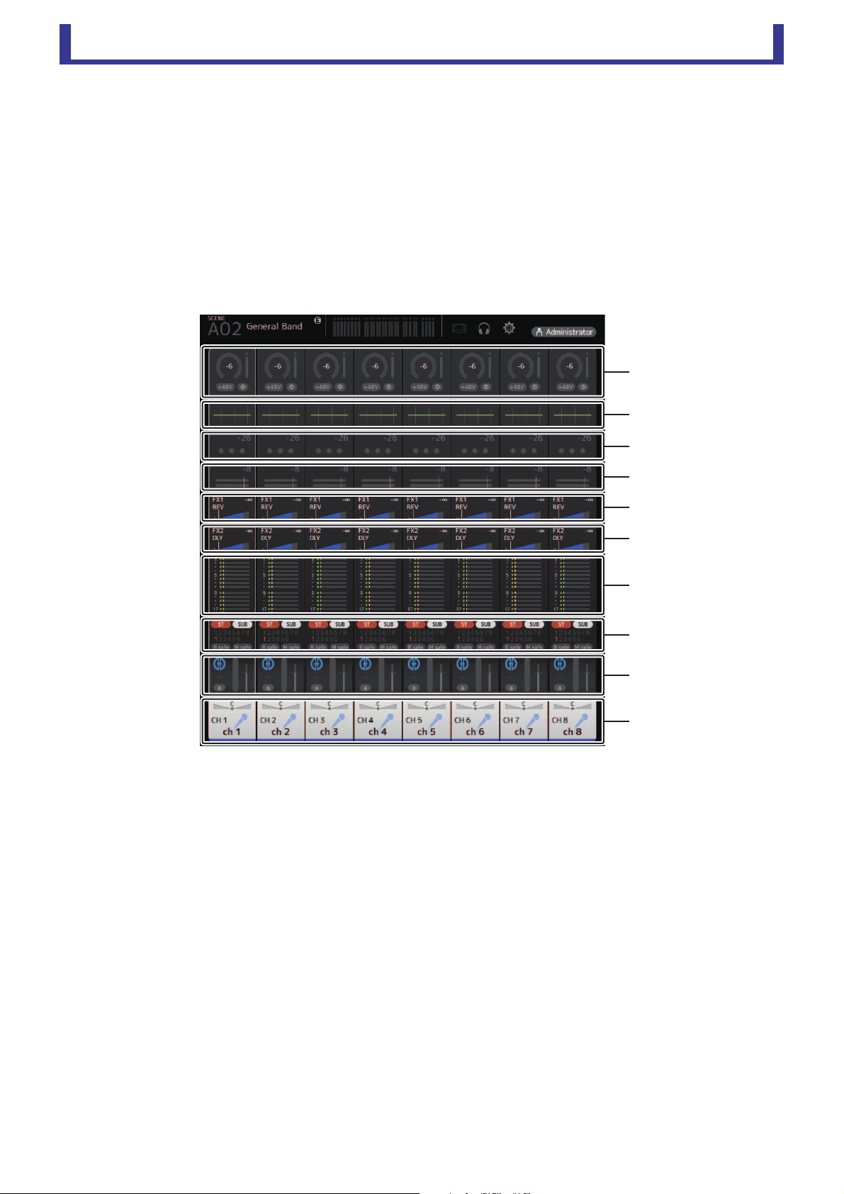
OVERVIEW screen
Displays information about the channel strips. This is the screen displayed after startup.
From here you can move to other screens depending on the operations that you want to perform.
You can return to the OVERVIEW screen at any time by pressing the HOME button in the HOME/LIBRARY area.
You can drag up and down to see other areas of the OVERVIEW screen.
You can also drag left and right to see other channels.
The content of the OVERVIEW screen varies depending on the type of channels you are displaying.
Input channels
1 Displays the INPUT screen (page 45).
2 Displays the EQ screen (page 48).
3 Displays the GATE screen (page 51).
4 Displays the COMP screen (page 53).
5 Displays the FX1 screen (page 55).
6 Displays the FX2 screen (page 55).
7 Displays the SEND TO AUX screen (page 62).
8 Displays the ASSIGN screen (page 63).
9 Displays the AUTOMIXER screen (page 64).
0 Displays the CH VIEW screen (page 66).
ձ
ղ
ճ
մ
յ
ն
շ
ո
չ
պ
Main display area
User’s Guide
TF Editor
-
34
-
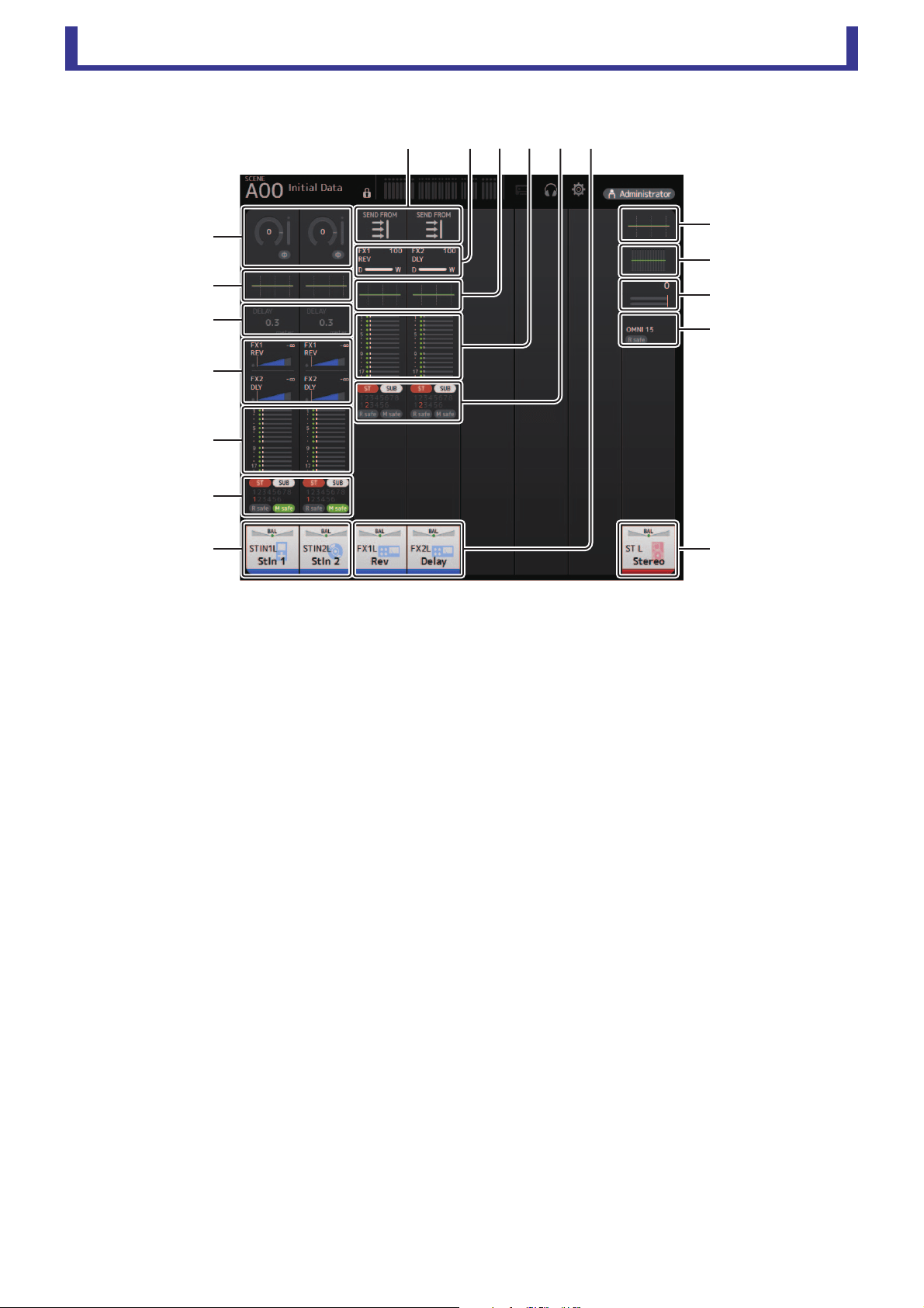
Stereo channels
1 Displays the INPUT screen (page 45).
2 Displays the EQ screen (page 48).
3 Displays the DELAY screen (page 84).
4 Displays the FX1/FX2 screen (page 55).
5 Displays the SEND TO AUX screen (page 62).
6 Displays the ASSIGN screen (page 63).
7 Displays the CH VIEW screen (page 66).
8 Displays the GEQ screen (page 79).
9 Displays the COMP screen (page 53).
0 Displays the OUTPUT screen (page 81).
A Displays the SEND FROM screen (page 82).
ջղմյն
ղ
ո
չ
պ
շ
շ
շ
ն
ձ
ղ
ճ
մ
յ

Main display area
User’s Guide
TF Editor
-
35
-
AUX1–AUX8 channels
1 Displays the SEND FROM screen (page 82).
2 Displays the EQ screen (page 48).
3 Displays the GEQ screen (page 79).
4 Displays the COMP screen (page 53).
5 Displays the OUTPUT screen (page 81).
6 Displays the CH VIEW screen (page 66).
AUX 9/10–19/20 channels, SUB channel
1 Displays the SEND FROM screen (page 82).
2 Displays the EQ screen (page 48).
3 Displays the GEQ screen (page 79).
4 Displays the COMP screen (page 53).
5 Displays the OUTPUT screen (page 81).
6 Displays the CH VIEW screen (page 66).
ձ
ղ
ճ
մ
յ
ն
ձ
ղ
ճ
մ
ձ
ղ
ճ
յ
յ
նն
Main display area
User’s Guide
TF Editor
-
36
-
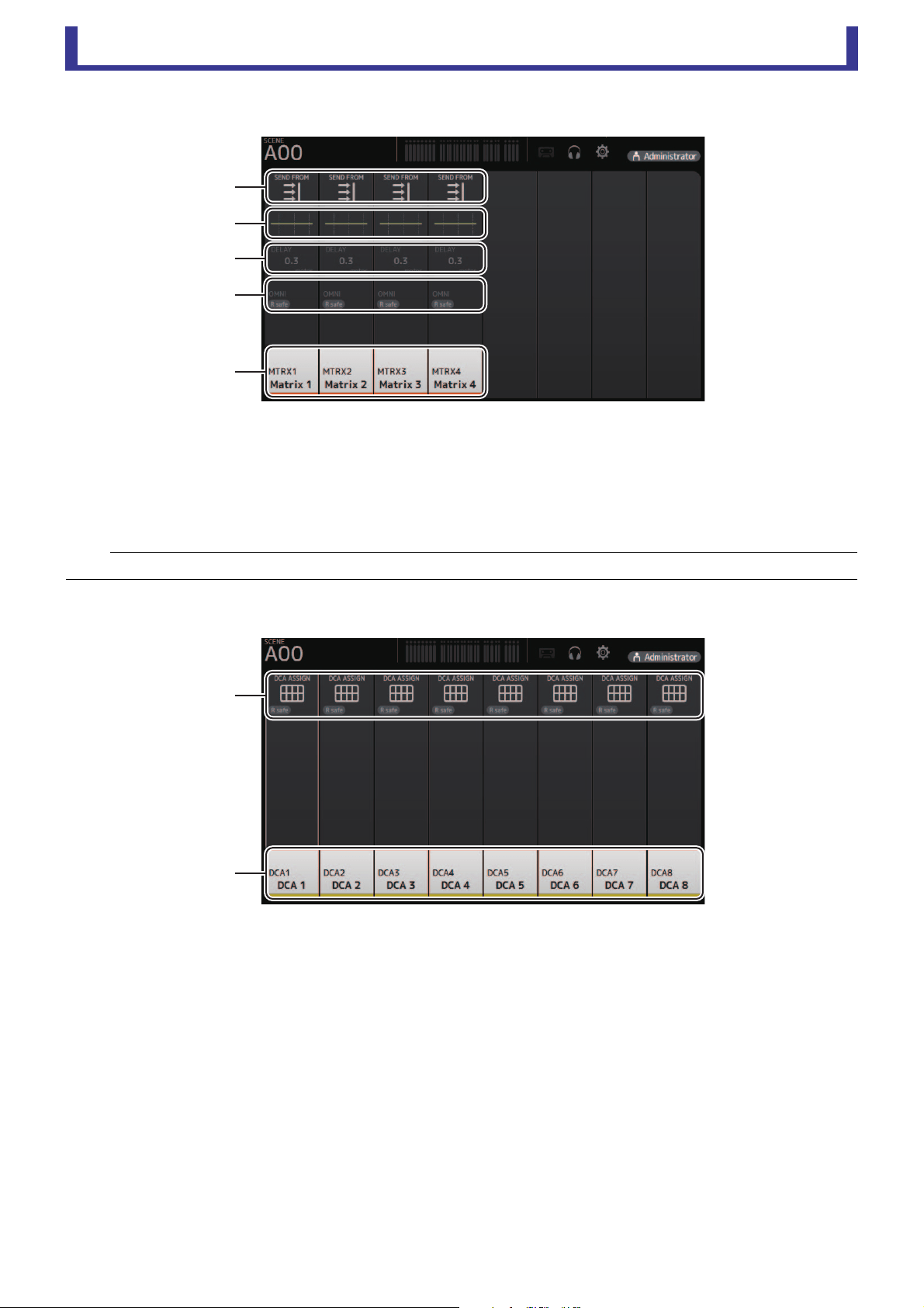
MATRIX1–MATRIX4 channels
1 Displays the SEND FROM screen (page 82).
2 Displays the EQ screen (page 48).
3 Displays the DELAY screen (page 84).
4 Displays the OUTPUT screen (page 81).
5 Displays the CH VIEW screen (page 66).
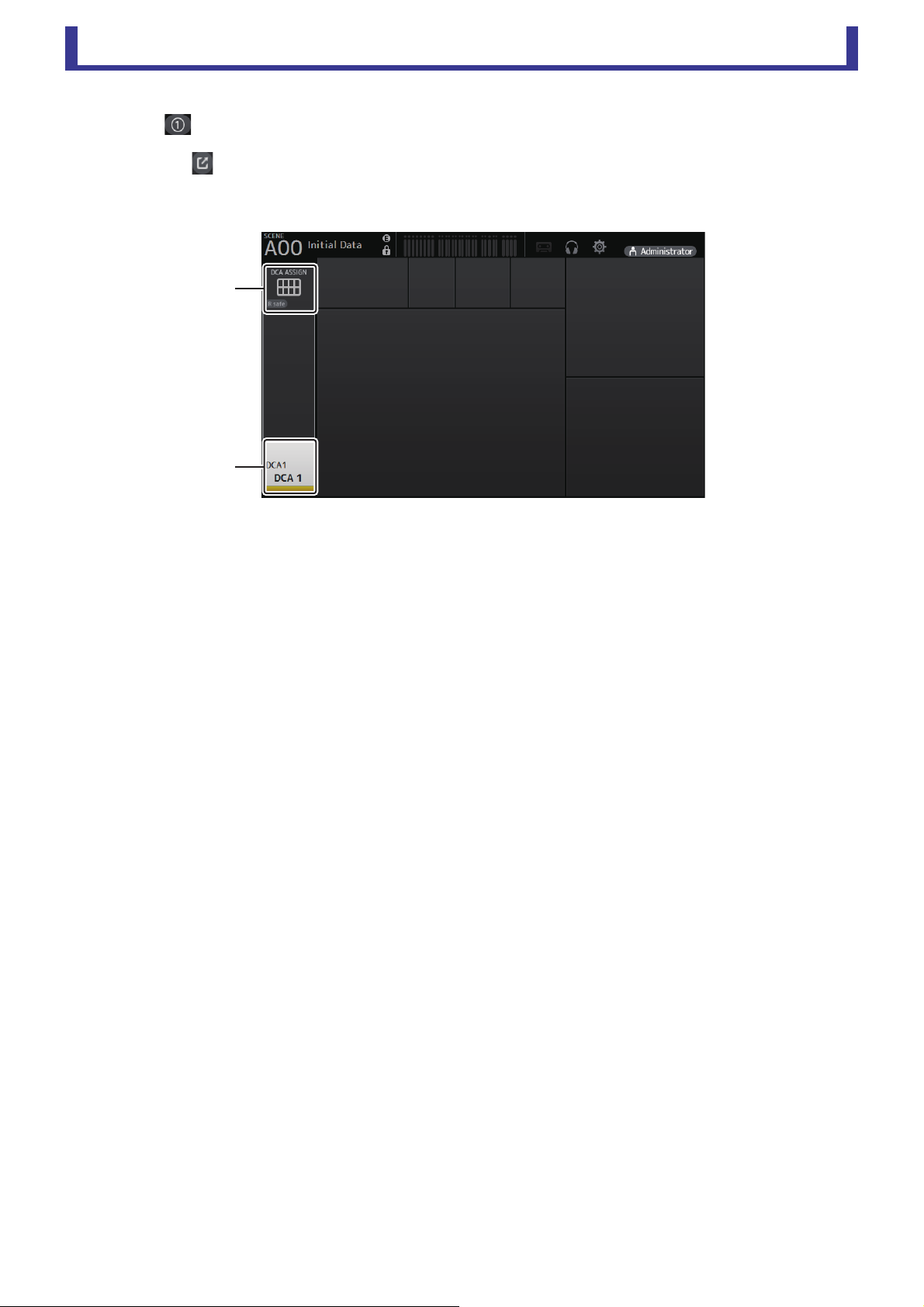
Group channels
1 Displays the DCA ASSIGN screen (page 83).
2 Displays the CH VIEW screen (page 66).
NOTE
MATRIX channels 1–4 are displayed in the OUTPUT FADER BANK.
ձ
ղ
ճ
մ
յ
ձ
ղ
Main display area
User’s Guide
TF Editor
-
37
-
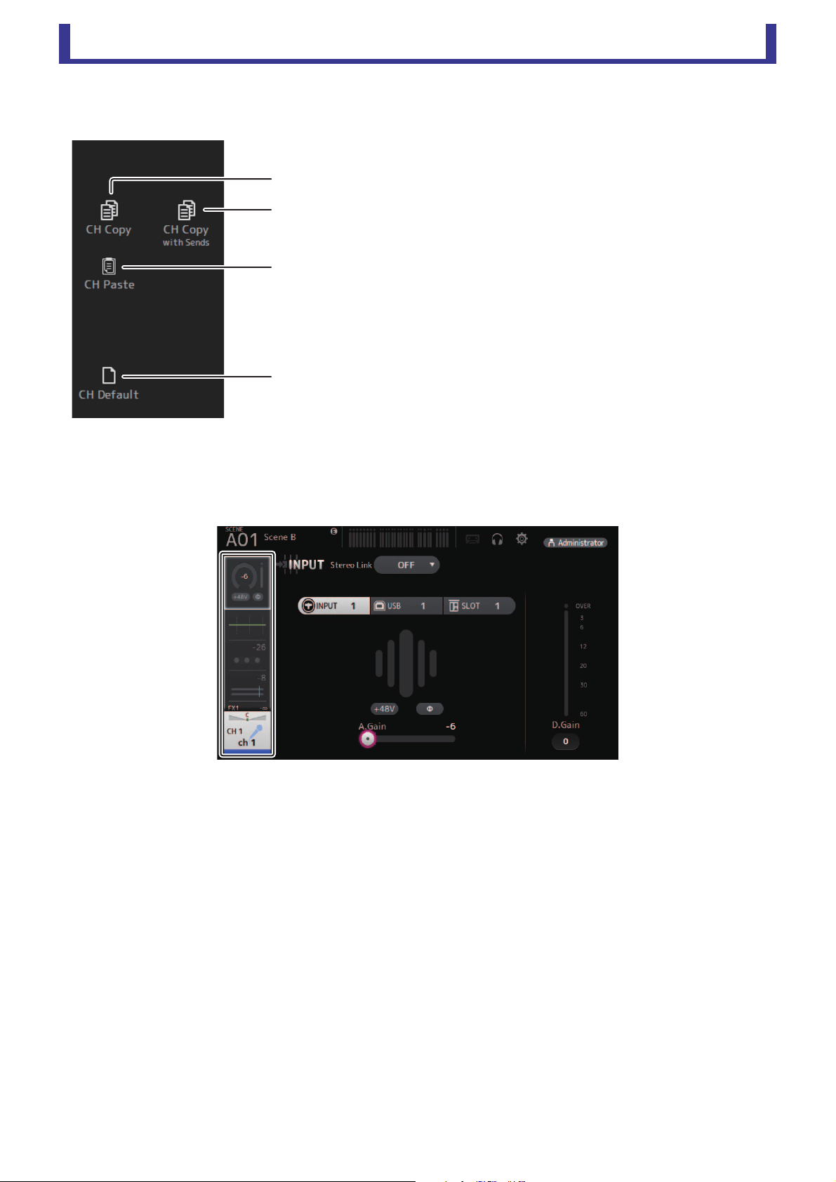
OVERVIEW screen menu
The following items are displayed in the menu area when the OVERVIEW screen is displayed.
Navigation area
The navigation area is displayed on the left side of each configuration screen.
When a configuration screen is displayed, the content of the navigation area is the same as the content displayed for that channel
in the OVERVIEW screen.
1 CH Copy
Copies the settings of the current channel.
2 CH Copy with Sends
Copies settings from the selected AUX/MATRIX channel, as well as the settings
sent from the sends of each channel.
3 CH Paste/CH Paste with Sends
Pastes the channel settings copied using CH Copy or the settings that were copied
using CH Copy with Send, and applies them to the selected channel.
4 CH Default
Resets the settings of the current channel to their default values.
ղ
ճ
ձ
մ
Main display area
User’s Guide
TF Editor
-
38
-
SELECTED CHANNEL screen
CH1–CH32
1 Displays the FX1 screen (page 55).
2 Displays the FX2 screen (page 55).
3 Displays the SEND TO AUX screen (page 62).
4 Displays the ASSIGN screen (page 63).
5 Displays the CH VIEW screen (page 66).
6 Displays the HA status.
You can adjust the gain by clicking the text box to highlight it, and then use your mouse wheel to adjust the setting.
Click when highlighted to display the INPUT screen (page 45).
Two HAs are displayed on channels for which the stereo link is configured.
7 Displays the ON/OFF status for the input port and DIRECT OUT.
Click to display the CH VIEW screen (page 66).
8 Displays the AUTOMIXER screen (page 64).
9 Displays the LIBRARY screen (page 30).
0 Controls the channel EQ.
The button switches between 1-knob mode and manual mode.
Select the 1-knob EQ mode type and switch between filter types on the EQ screen.
Click the icon to display the EQ screen (page 48).
A Configures the GATE for the channel.
Click the icon to display the GATE screen (page 51).
B Configures the COMP for the channel.
The button switches between 1-knob mode and manual mode.
Click the icon to display the COMP screen (page 53).
NOTE
In the EQ, GEQ, GATE and COMP sections of the SELECTED CHANNEL screen, you can use drag and drop, as well as clicking on each parameter
and then adjusting the settings using the mouse wheel, with the parameter highlighted.
ձ
ղ
ճ
մ
յ
նշոչ
ջ
ռ
պ

Main display area
User’s Guide
TF Editor
-
39
-
CH33–CH40
1 Displays the FX1 screen (page 55).
2 Displays the FX2 screen (page 55).
3 Displays the SEND TO AUX screen (page 62).
4 Displays the ASSIGN screen (page 63).
5 Displays the CH VIEW screen (page 66).
6 Displays the HA status.
You can adjust the gain by clicking the text box to highlight it, and then use your mouse wheel to adjust the setting.
Click when highlighted to display the INPUT screen (page 45).
7 Displays the input port.
8 Displays the LIBRARY screen (page 30).
9 Controls the channel EQ.
The button switches between 1-knob mode and manual mode.
Select the 1-knob EQ mode type and switch between filter types on the EQ screen.
Click the icon to display the EQ screen (page 48).
ST IN1L–2R
1 Displays the FX1 screen (page 55).
2 Displays the FX2 screen (page 55).
3 Displays the SEND TO AUX screen (page 62).
4 Displays the ASSIGN screen (page 63).
5 Displays the CH VIEW screen (page 66).
ձ
ղ
ճ
մ
յ
նշ ո
չ
ձ
ղ
ճ
մ
յ
նշոչ
պ
Main display area
User’s Guide
TF Editor
-
40
-
6 Displays the HA status.
You can adjust the gain by clicking the text box to highlight it, and then use your mouse wheel to adjust the setting.
Click when highlighted to display the INPUT screen (page 45).
7 Displays the input port.
8 Displays the DELAY screen (page 84).
9 Displays the LIBRARY screen (page 30).
0 Controls the channel EQ.
The button switches between 1-knob mode and manual mode.
Select the 1-knob EQ mode type and switch between filter types on the EQ screen.
Click the icon to display the EQ screen (page 48).
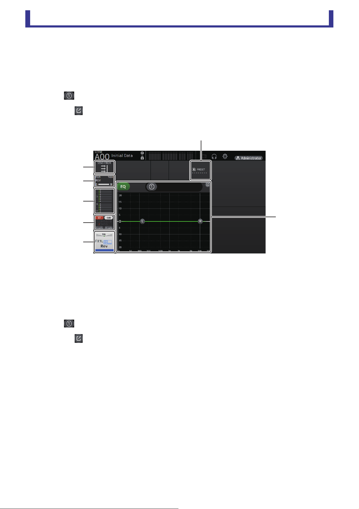
FX1L–2R
1 Displays the SEND FROM screen (page 82).
2 Displays the FX screen (page 55).
3 Displays the SEND TO AUX screen (page 62).
4 Displays the ASSIGN screen (page 63).
5 Displays the CH VIEW screen (page 66).
6 Displays the LIBRARY screen (page 30).
7 Controls the channel EQ.
The button switches between 1-knob mode and manual mode.
Select the 1-knob EQ mode type and switch between filter types on the EQ screen.
Click the icon to display the EQ screen (page 48).
ձ
ղ
ճ
մ
յ
ն
շ
Main display area
User’s Guide
TF Editor
-
41
-
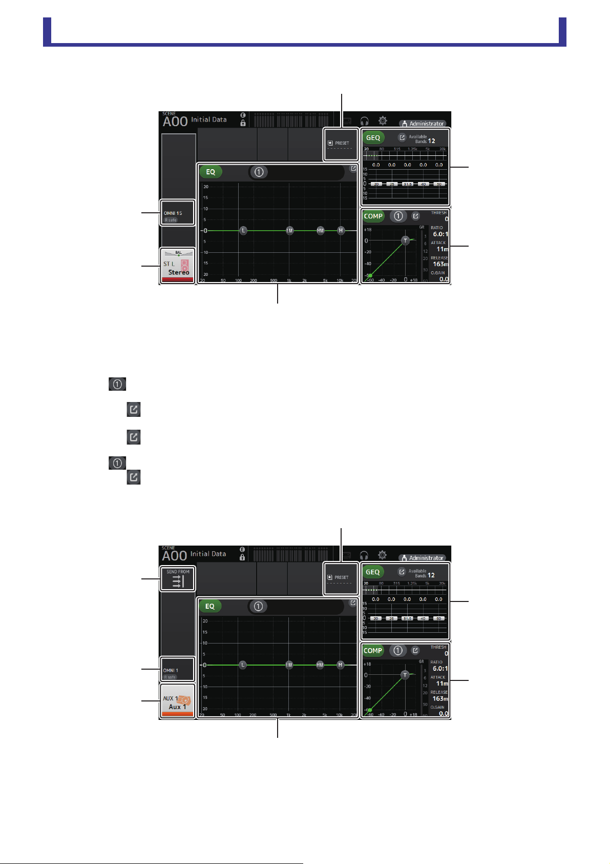
ST L/R
1 Displays the OUTPUT screen (page 81).
2 Displays the CH VIEW screen (page 66).
3 Displays the LIBRARY screen (page 30).
4 Controls the channel EQ.
The button switches between 1-knob mode and manual mode.
Select the 1-knob EQ mode type and switch between filter types on the EQ screen.
Click the icon to display the EQ screen (page 48).
5 Controls the channel GEQ.
Click the icon to display the GEQ screen (page 79).
6 Controls the channel COMP.
The button switches between 1-knob mode and manual mode.
Click the icon to display the COMP screen (page 53).
AUX1–AUX8
1 Displays the SEND FROM screen (page 82).
2 Displays the OUTPUT screen (page 81).
3 Displays the CH VIEW screen (page 66).
4 Displays the LIBRARY screen (page 30).
ձ
ղ
ճ
յ
ն
մ
ձ
ղ
ճ
մ
ն
շ
յ
Main display area
User’s Guide
TF Editor
-
42
-
5 Controls the channel EQ.
The button switches between 1-knob mode and manual mode.
Select the 1-knob EQ mode type and switch between filter types on the EQ screen.
Click the icon to display the EQ screen (page 48).
6 Controls the channel GEQ.
Click the icon to display the GEQ screen (page 79).
7 Controls the channel COMP.
The button switches between 1-knob mode and manual mode.
Click the icon to display the COMP screen (page 53).
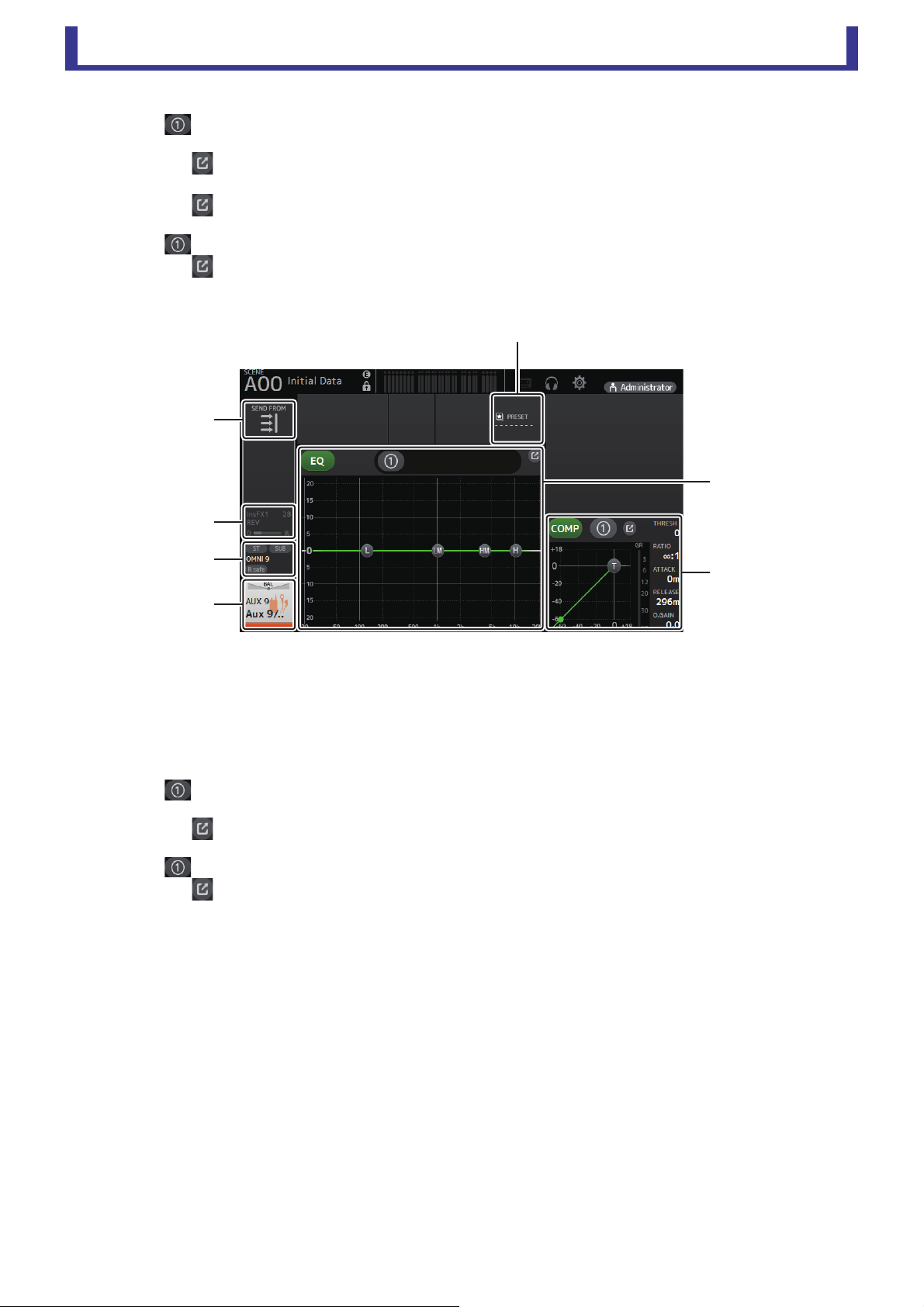
AUX9–AUX20
1 Displays the SEND FROM screen (page 82).
2 Displays the FX screen (page 55).
3 Displays the OUTPUT screen (page 81).
4 Displays the CH VIEW screen (page 66).
5 Displays the LIBRARY screen (page 30).
6 Controls the channel EQ.
The button switches between 1-knob mode and manual mode.
Select the 1-knob EQ mode type and switch between filter types on the EQ screen.
Click the icon to display the EQ screen (page 48).
7 Controls the channel COMP.
The button switches between 1-knob mode and manual mode.
Click the icon to display the COMP screen (page 53).
ձ
ղ
ճ
մ
յ
շ
ն
Main display area
User’s Guide
TF Editor
-
43
-
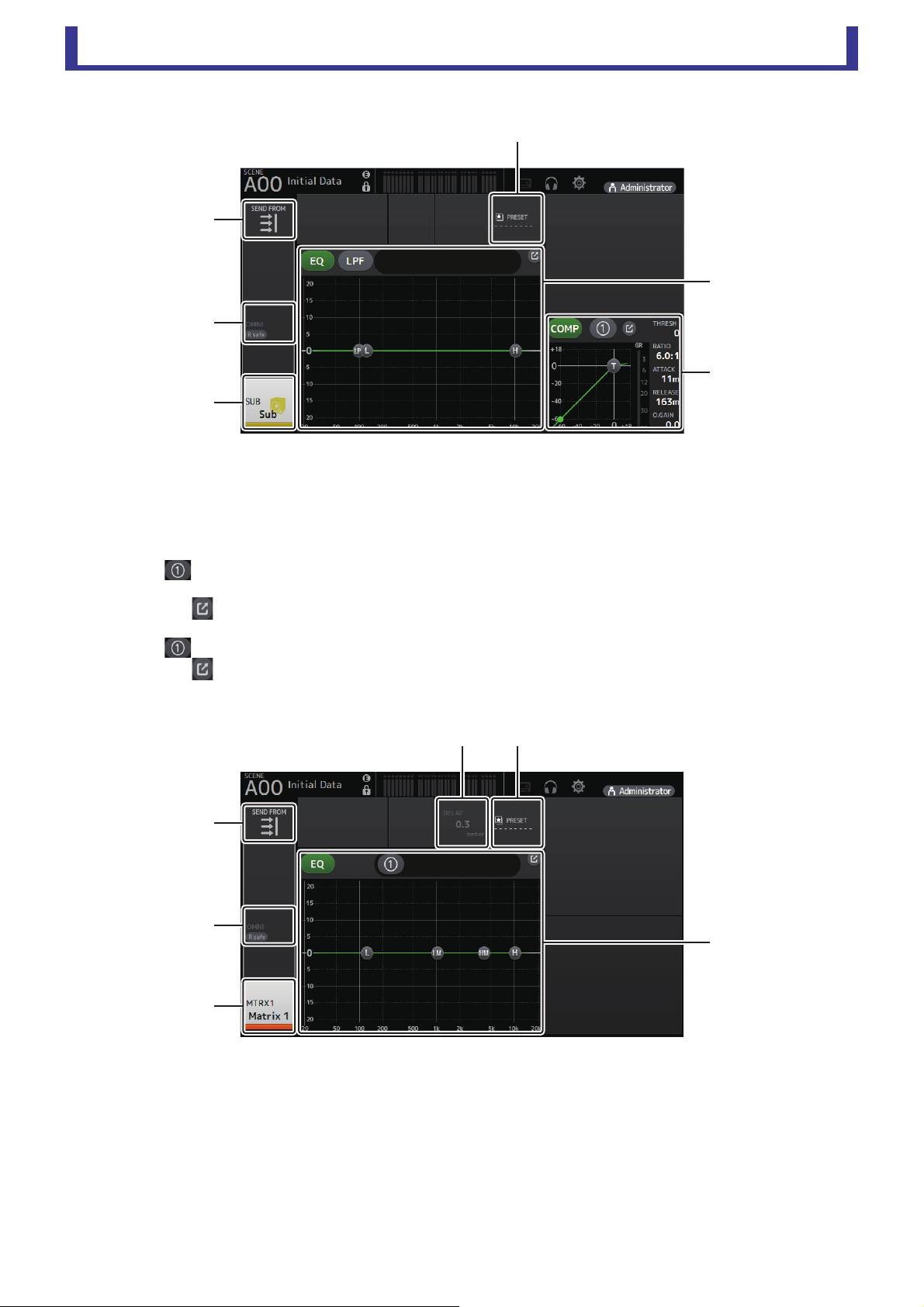
SUB
1 Displays the SEND FROM screen (page 82).
2 Displays the OUTPUT screen (page 81).
3 Displays the CH VIEW screen (page 66).
4 Displays the LIBRARY screen (page 30).
5 Controls the channel EQ.
The button switches between 1-knob mode and manual mode.
Select the 1-knob EQ mode type and switch between filter types on the EQ screen.
Click the icon to display the EQ screen (page 48).
6 Controls the channel COMP.
The button switches between 1-knob mode and manual mode.
Click the icon to display the COMP screen (page 53).
MATRIX1–MATRIX4
1 Displays the SEND FROM screen (page 82).
2 Displays the OUTPUT screen (page 81).
3 Displays the CH VIEW screen (page 66).
4 Displays the DELAY screen (page 84).
5 Displays the LIBRARY screen (page 30).
ձ
ղ
ճ
մ
ն
յ
ձ
ղ
ճ
մյ
ն
Main display area
User’s Guide
TF Editor
-
44
-
6 Controls the channel EQ.
The button switches between 1-knob mode and manual mode.
Select the 1-knob EQ mode type and switch between filter types on the EQ screen.
Click the icon to display the EQ screen (page 48).
DCA1–DCA8
1 Displays the DCA ASSIGN screen (page 83).
2 Displays the CH VIEW screen (page 66).
ձ
ղ
Main display area
User’s Guide
TF Editor
-
45
-
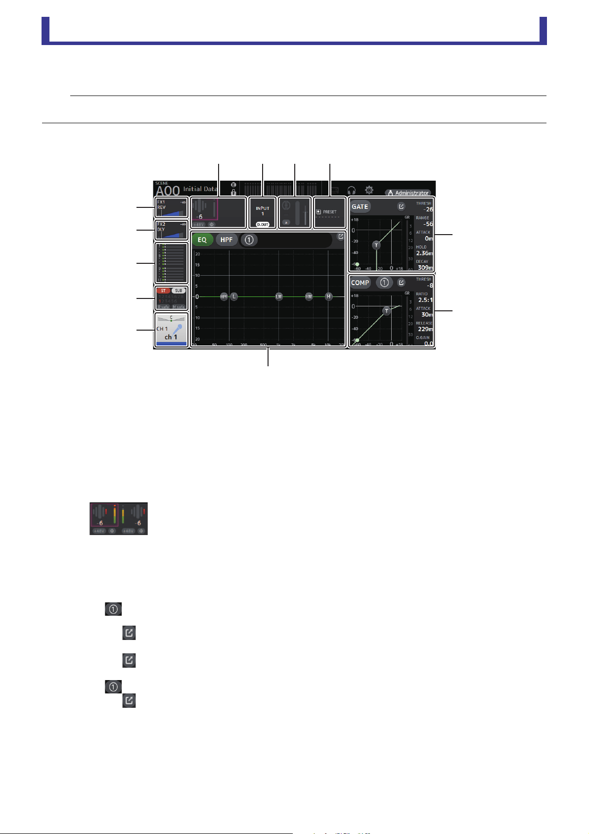
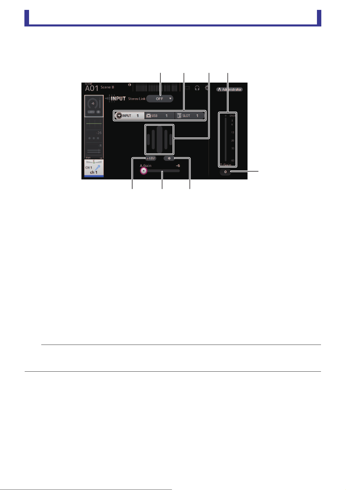
INPUT screen
Allows you to change the stereo link setting, select an input source, turn phantom power on and off, turn phasing on and off, and
adjust input gain.
1 Stereo link selection button
Allows you to select whether two adjacent mono input channels are linked as a stereo pair, or behave as two separate mono
channels.
Click to display the popup menu.
OFF: Stereo link is disabled.
CH1&2: Stereo link is enabled. When stereo link is enabled, the odd numbered channel is the left side of the stereo pair, and
the even numbered one is the right. The channel numbers displayed in the popup menu depend on the channel
whose settings you are editing.
CH2&3: Stereo link is enabled. When stereo link is enabled, the even numbered channel is the left side of the stereo pair, and
the odd numbered one is the right. The channel numbers displayed in the popup menu depend on the channel
whose settings you are editing.
2 Input selection buttons
Allows you to select the channel's input source (input port). The available sources depend on the channel whose settings you
are editing.
INPUT: The device connected to the INPUT jack will be used as the input source.
USB: The computer connected to the USB TO HOST connector will be used as the input source.
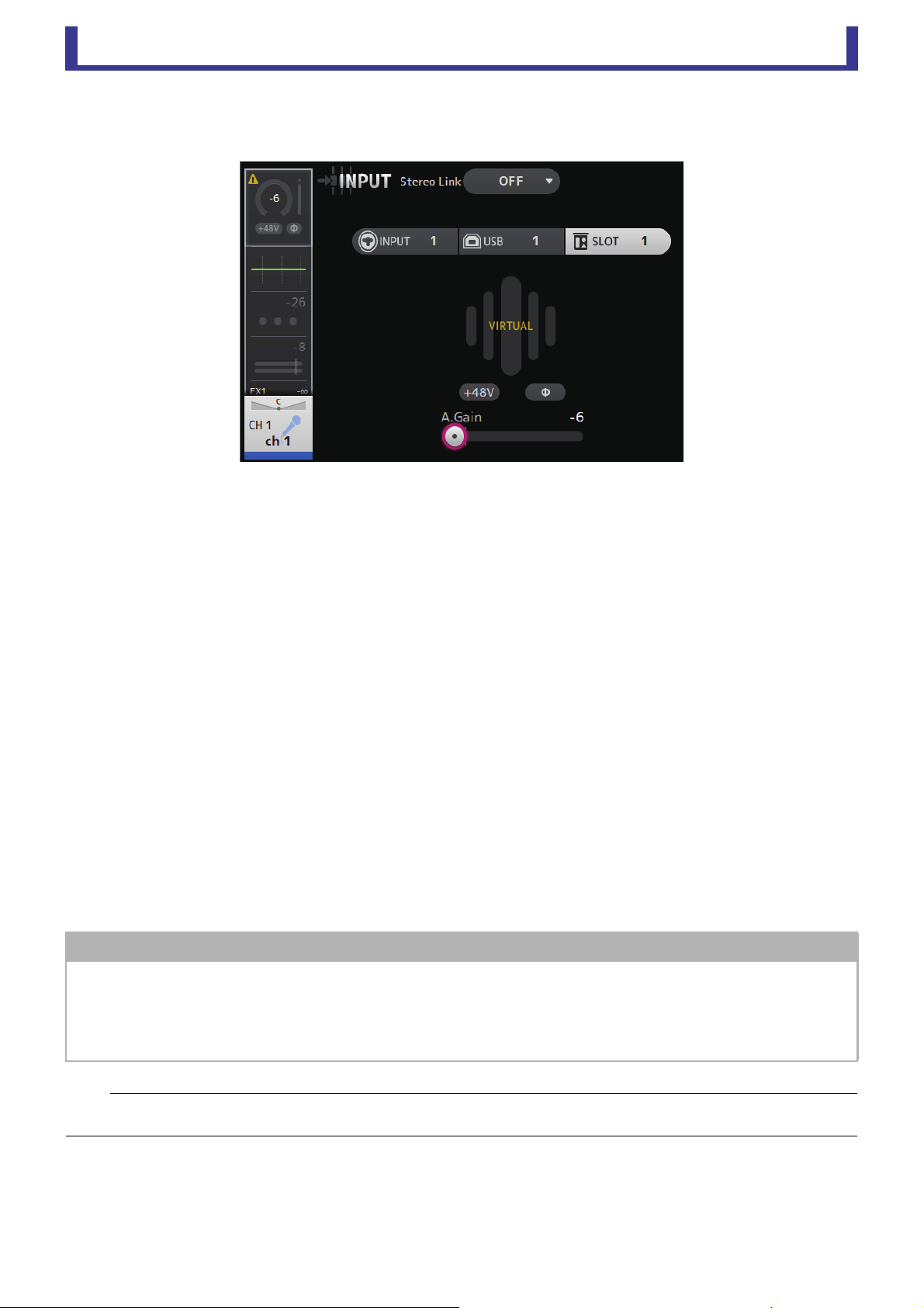
SLOT: Allows you to select an input from the NY64-D installed in the expansion slot. Use this button when selecting an
input from a Tio1608-D or stage box connected to the NY64-D and the Dante network.
Playback: Displayed for ST IN1. Allows you to select a USB storage device that is connected to the USB connector on the
front panel as an input.
NOTE
When USB is selected, the gain slider (7) adjusts digital gain, and the +48V button (8) is not displayed.
When SLOT is selected, analog gain adjustment and the +48V button cannot be used if the HA Control button on the SLOT SETUP screen is not
turned on. Additionally, for inputs from a device whose head amp cannot be controlled, the gain slider (
7) becomes a digital gain adjustment, and
the +48V button (
8) is not displayed.
ձղ ճմ
յ
նշո
Main display area
User’s Guide
TF Editor
-
46
-
Even if you select SLOT as the input source, if a source is not actually available (such as when there is no NY64-D installed,
no Tio1608-D or stage box connected, no Dante patching, etc.), this "virtual HA" state is displayed in the HA box area of this
screen, the OVERVIEW screen, and the CH VIEW screen.
3 GainFinder
Displays the input level. When adjusting the input gain, adjust it so that the center of the GainFinder lights up.
4 Level meter
Displays the post gain adjustment level.
5 Digital gain text box
Allows you to adjust digital gain. The default setting is 0 db.
You can click the text box to highlight it, then use your mouse wheel to adjust the setting. You can also click the text box
again to adjust the setting using your computer keyboard.
6 Φ (phase) button
Allows you to reverse the phase.
When turned on, the input signal's phase is reversed.
7 Gain sliders
When the INPUT button is selected, the slider adjusts the analog gain of the head amp.
The PAD (-24 dB) will be switched on or off when the analog gain is adjusted between +17 dB and +18 dB.
When the USB button is selected, the slider adjusts digital gain.
8 +48V button
Turns phantom power (+48V) to the head amp on and off.
On: Phantom power is turned on.
Off: Phantom power is turned off.
When the USB button is selected, the +48V button is not displayed.
When the +48V Master button on the SYSTEM SETUP screen is turned off, phantom power will not be supplied even if the
+48V button on this screen turned on (page 19).
NOTICE
Information about phantom power
When phantom power is not needed, set the +48V button to the off position.
Observe the following when using phantom power to prevent damage to the console or connected devices, and signal noise.
• Do not set the +48V button to the on position when the device connected to the input jack does not require phantom power.
• Do not connect or disconnect cables when the +48V button is set to the on position.
• Before turning phantom power on or off for a channel, first set the channel's volume to the minimum level.
NOTE
When using phantom power, noise may be generated if there is a difference in the impedance between the hot and cold of the device connected
to an input jack.

Main display area
User’s Guide
TF Editor
-
47
-
9 Gain Unlink button
Displayed for stereo channels and for channels that have stereo link turned on.
While you are holding the button down, gain for the left and right channels can temporarily be adjusted individually. When
you release the button, the gain for both channels can be adjusted together but the difference in gain between the two
channels is maintained. To adjust a channel's gain, click the gain slider of the corresponding channel and then rotate the
mouse wheel while holding down the Gain Unlink button.
Input screen menu
The following items are displayed in the menu area when the INPUT screen is displayed.
1 All INPUT
Allows you to assign the INPUT jacks as the input source for all input channels.
2 All USB
Allows you to assign the USB TO HOST connector as the input source for all input
channels.
3 All SLOT
Switches all inputs to input sources of Dante network devices that are connected to the
NY64-D installed in the expansion slot.
The input source for the following channels will be changed.
TF5:
CH 1–32 (when CH 1–32 are selected)
CH 33–40 (when CH 33–40 are selected)
TF3:
CH 1–24 (when CH 1–24 are selected)
CH 25–32 (when CH 25–32 are selected)
CH 33–40 (when CH 33–40 are selected)
TF1/TF-RACK:
CH 1–16 (when CH 1–16 are selected)
CH 17–32 (when CH 17–32 are selected)
չ
ձ
ղ
ճ
Main display area
User’s Guide
TF Editor
-
48
-
EQ screen
Controls the EQ for each channel.
4-band parametric EQ is available for CH 1–32, AUX 1–19/20, STEREO, and MATRIX 1–4. 2-band parametric EQ is available for
CH 33–40, ST IN 1, ST IN 2, FX1, FX2, and SUB.
You can adjust settings using 1-knob mode, which allows you to use the mouse wheel to easily adjust settings, or manual mode,
which allows you to adjust each parameter individually.
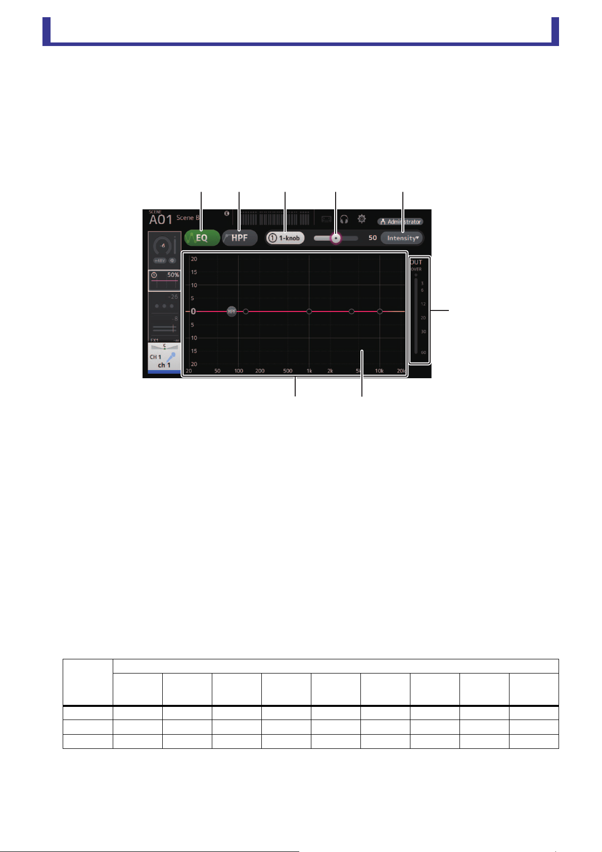
4-band parametric EQ
1 EQ button
Turns the EQ on and off.
2 HPF button
Turns the HPF (high-pass filter) on and off.
Displayed for CH 1–40.
3 1-knob button
Switches between 1-knob mode and manual mode.
When using 1-knob mode, the 1-knob level slider is displayed.
4 1-knob level slider
Adjusts the amount of 1-knob EQ applied.
When using manual mode, information about the selected band's Q, F, and G is displayed here.
5 EQ mode type selection button
When using 1-knob mode, allows you to select the 1-knob EQ mode type.
Select [Vocal] for vocal channels, otherwise select [Intensity].
When set to [Intensity], you can adjust the EQ to a setting between flat and increased intensity of the EQ settings you made
using manual mode.
For output channels, [Loudness] is available. This setting allows you to boost low and high tones.
The available modes depend on the channel whose settings you are editing.
In manual mode, you can select the filter type. You can select low-band and high-band filter.
For CH 1–40, the available low-band filters are low-shelving type and bell type.
For other channels (i.e., for channels that do not have an HPF), the available low-band filters are HPF, low-shelving type, and bell type.
The available high-band filters are LPF, high-shelving type, and bell type.
Type
Channel
CH 1–32
HPF +
4-band
CH 33–40
HPF +
2-band
ST IN
2-band
FX
2-band
STEREO
4-band
AUX 1–8
4-band
AUX9/10–
AUX19/20
4-band
MATRIX1–4
4-band
SUB
2-band
+ LPF
Intensity
○○○○○○○○
×
Vocal
○
×
×××××××
Loudness
×××
×
○○○○
×
ձղ ճ մ յ
ն
շ
ո
Main display area
User’s Guide
TF Editor
-
49
-
6 EQ output level meter
Displays the EQ output level.
7 EQ graph
Displays the parameter settings of the EQ and filter. As you adjust the settings of each band, the results are reflected in the
graph.
When using 1-knob EQ mode, you can adjust the 1-knob level slider.
When using manual mode, you can drag the handles displayed in the graph to adjust the corresponding settings. When HPF
is turned on, you can drag the HPF handle to adjust the cutoff frequency. You can also adjust HPF independently when using
the Intensity type for 1-knob EQ mode.
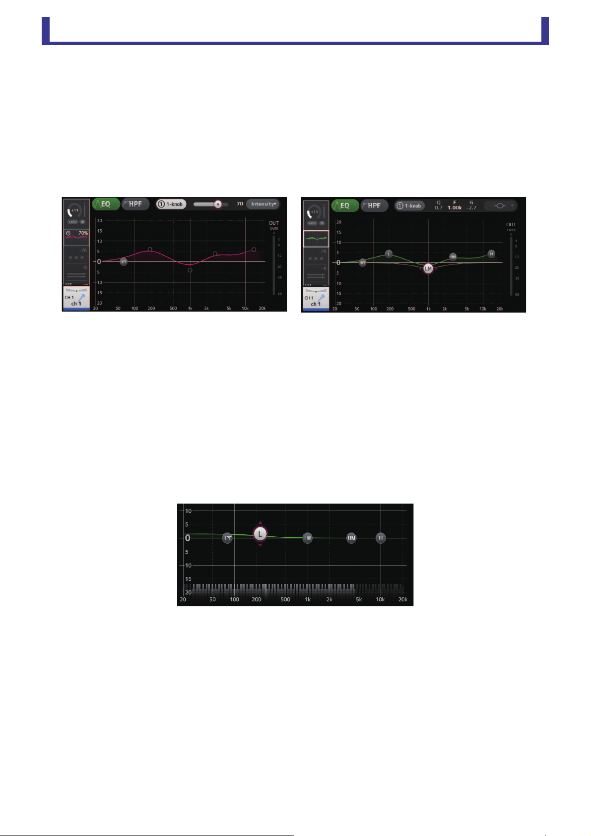
<1-knob EQ mode> <Manual mode>
How does 1-knob EQ mode work?
1-knob EQ mode allows you to adjust several parameters at once with just one operation. It makes EQ adjustment quick and easy.
The console contains Presets that are configured for a variety of instruments. You can use 1-knob EQ mode to adjust the EQ
settings that are saved in Presets without disturbing the overall balance of your mix.
You can even configure EQ settings using manual mode, then switch to 1-knob EQ mode and use the Intensity type to adjust the
amount of EQ applied to the channel. In this case you can adjust from 0% (no EQ applied) to 50% (the EQ settings you made using
manual mode) and 100% (increased intensity of the EQ settings you made using manual mode). This makes it very easy to fine-
tune your EQ settings with just one operation.
If 1-knob EQ mode type is set to Vocal or Loudness, you can adjust the EQ between 0% (no EQ applied) and 100% (maximum EQ
applied).
8 Keyboard display
You can click the bottom of the graph where no parameters are displayed to display a keyboard. This helps you visualize how
the frequencies correlate to musical pitches.
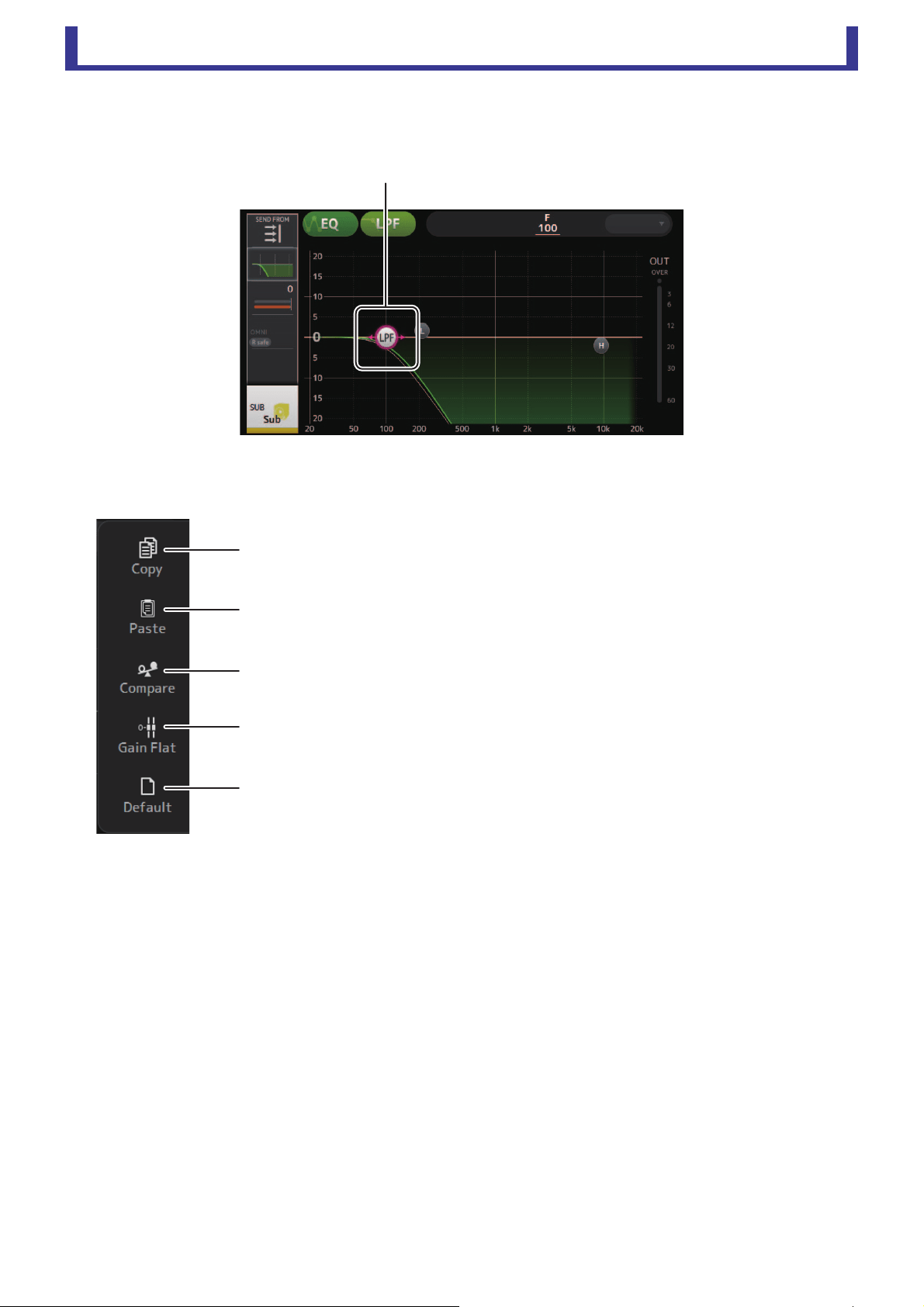
Main display area
User’s Guide
TF Editor
-
50
-
Setting LPF
The SUB channel can use the LPF to cut high frequencies independent of the EQ, ideal for adjusting the signal sent to a sub-
woofer.
EQ screen menu
The following items are displayed in the menu area when the EQ screen is displayed.
1 Copy
Copies the EQ parameters of the selected channel to the clipboard.
2 Paste
Pastes the EQ parameters in the clipboard to the selected channel.
3 Compare
Allows you to compare the EQ parameters of the selected channel with the EQ
parameters in the clipboard by switching between the two.
4 Gain Flat
Sets the gain of the selected band to the flat position.
5 Default
Resets all EQ settings to their default values.
Drag to adjust
ձ
ղ
ճ
մ
յ

Main display area
User’s Guide
TF Editor
-
51
-
GATE screen
Allows you to configure the noise gate for each channel. When the input signal level is lower than a specified amount (threshold),
the output signal is reduced by a specified amount (range). GATE is available for CH 1–32.
1 GATE button
Turns the gate on and off.
2 Gate input level meter
Displays the pre-gate level.
3 Threshold slider
Determines the level at which the gate is applied.
4 Gate graph
Displays a visual representation of the gate level.
5 Range slider
Determines the amount by which the signal will be lowered when the gate is applied.
6 Attack slider
When the input signal exceeds the threshold, this setting determines how quickly the gate opens.
7 Hold slider
When the input signal drops below the threshold, this setting determines how much time passes before the gate closes.
8 Decay slider
After the hold time passes, this setting determines how quickly the gate closes. The value here is expressed as the time
required for the level to change by 6 dB.
9 GR (gain reduction) meter
Displays the amount by which the signal's gain is reduced.
0 OUT (gate output) meter
Displays the post-gate level.
ձյնշ
չ
պ
ոմճղ
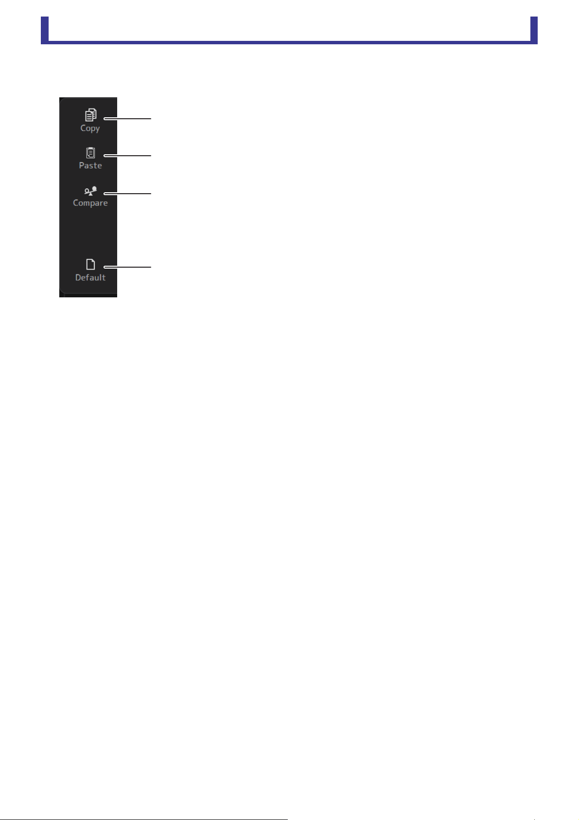
Main display area
User’s Guide
TF Editor
-
52
-
GATE screen menu
The following items are displayed in the menu area when the GATE screen is displayed.
1 Copy
Copies the GATE parameters of the selected channel to the clipboard.
2 Paste
Pastes the GATE parameters in the clipboard to the selected channel.
3 Compare
Allows you to compare the GATE parameters of the selected channel with the GATE
parameters in the clipboard by switching between the two.
4 Default
Resets GATE settings to their default values.
ձ
ղ
ճ
մ
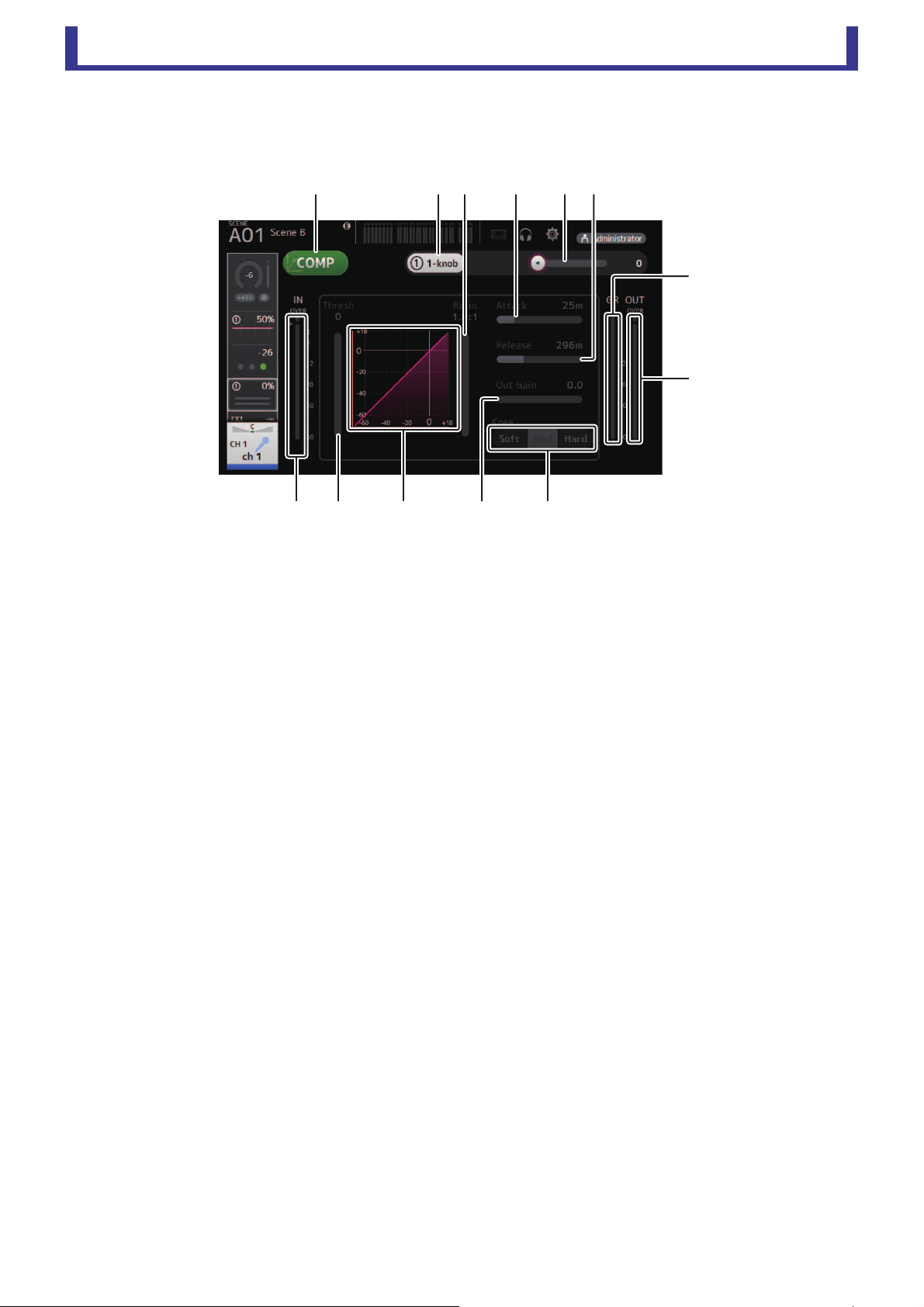
Main display area
User’s Guide
TF Editor
-
53
-
COMP screen
Allows you to configure the compressor for each channel. You can adjust settings using 1-knob mode, which allows you to use the
mouse wheel to easily adjust settings, or manual mode, which allows you to adjust each parameter individually.
1 COMP button
Turns the compressor on and off.
2 1-knob button
Switches between 1-knob mode and manual mode.
3 1-knob level slider (1-knob mode only)
Adjusts the amount of 1-knob COMP applied.
Not displayed during manual mode.
4 Compressor input level slider
Displays the pre-compressor level.
5 Threshold slider
Determines the level at which the compressor is applied.
6 Compressor graph
Displays a visual representation of the current settings.
7 Ratio slider
Determines the amount of compression that is applied.
8 Attack slider
When the input signal exceeds the threshold, this setting determines how quickly the maximum amount of compressor is
applied.
9 Release slider
When the input signal drops below the threshold, this setting determines how much time passes before the compressor is
no longer applied. The value here is expressed as the time required for the level to change by 6 dB.
0 Out Gain slider
Adjusts the output level of the compressor.
A Knee button
Determines the how gradual or sudden the curve is at the threshold. A soft knee means that compression is applied gradually
as the signal exceeds the threshold; a hard knee means a more sudden transition.
B GR (gain reduction) meter
Displays the amount by which the signal's gain is reduced.
C OUT (compressor output) meter
Displays the post-compressor level.
չ
ռ
ս
ջպնյմ
ձղշոճ

Main display area
User’s Guide
TF Editor
-
54
-
How does 1-knob COMP mode work?
1-knob COMP mode allows you to adjust the amount of compression applied to the signal with one operation. By sliding the 1-knob
level slider to the right, more compression is applied. In situations where raising the fader or gain could cause clipping at louder
points in the signal, compression can deliver a more consistent sound.
1-knob COMP takes some of the worry out of compression by allowing you to adjust the balance between threshold, ratio and out
gain easily.
COMP screen menu
The following items are displayed in the menu area when the COMP screen is displayed.
1 Copy
Copies the COMP parameters of the selected channel to the clipboard.
2 Paste
Pastes the COMP parameters in the clipboard to the selected channel.
3 Compare
Allows you to compare the COMP parameters of the selected channel with the COMP
parameters in the clipboard by switching between the two.
4 Default
Resets compressor settings to their default values.
ձ
ղ
ճ
մ
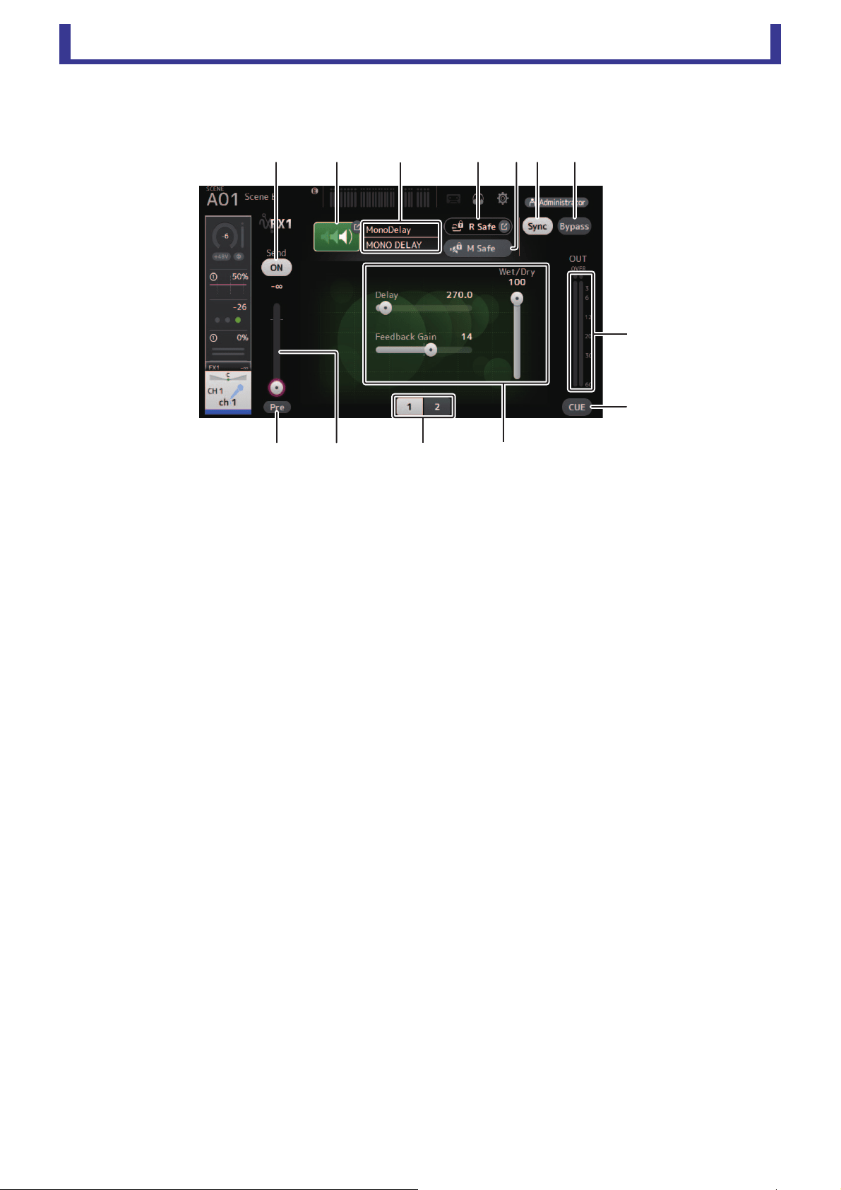
Main display area
User’s Guide
TF Editor
-
55
-
FX screen (FX1/2, InsFX1–6)
Allows you select an effect and edit its parameters.
1 Send button
Determines whether a signal is sent (on) or not sent (off) to the FX return channel.
Displayed for CH 1–40, ST IN 1 and ST IN 2.
2 EFFECT TYPE button
Displays the EFFECT TYPE screen, where you can select an effect type.
3 Effect type and name
Displays the type and name of the current effect.
4 R Safe (recall safe) indicator
Displays the recall safe status of the effects module.
Displays the RECALL SAFE screen (page 22).
5 M safe (mute safe) button
Turns mute safe on and off for the effects module.
6 FX send level slider
Allows you to adjust the amount of channel's signal sent to the effects module.
Displayed for CH 1–40, ST IN 1 and ST IN 2.
7 Pre button
Allows you to select whether the pre-fader or post-fader signal is processed by the effect module.
On: Before the fader
Off: After the fader
Displayed for CH 1–40, ST IN 1 and ST IN 2.
8 Parameter selection buttons
Click to display other parameters available for the current effect.
9 Parameter sliders
Allow you to adjust the parameters available for the current effect.
0 Sync button
Displayed for effects that have a tempo setting, such as delays.
A Bypass button
Allows you to bypass the effects module.
B Effects output level meter
Displays the output level of the effects module.
C CUE button
Turns cue on and off for the effects module.
ձղ ճ մ ջ
պ
չոնշ
ռ
ս
յ

Main display area
User’s Guide
TF Editor
-
56
-
Setting an insert effect
You can configure insert effects for AUX9/10–AUX19/20.
By default, insert effects are bypassed; turn the bypass off in order to use effect.
FX screen menu
The following items are displayed in the menu area when the FX screen is displayed.
EFFECT TYPE screen
Allows you to select the effect type. Click the desired button to make a selection.
1 Copy
Copies the effect parameters of the selected effect to the clipboard.
2 Paste
Pastes the effect parameters in the clipboard to the selected effect.
3 Compare
Allows you to compare the effect parameters of the selected effect with the effect
parameters in the clipboard by switching between the two.
4 Default
Resets the selected effect's settings to their default values.
ձ
ղ
ճ
մ
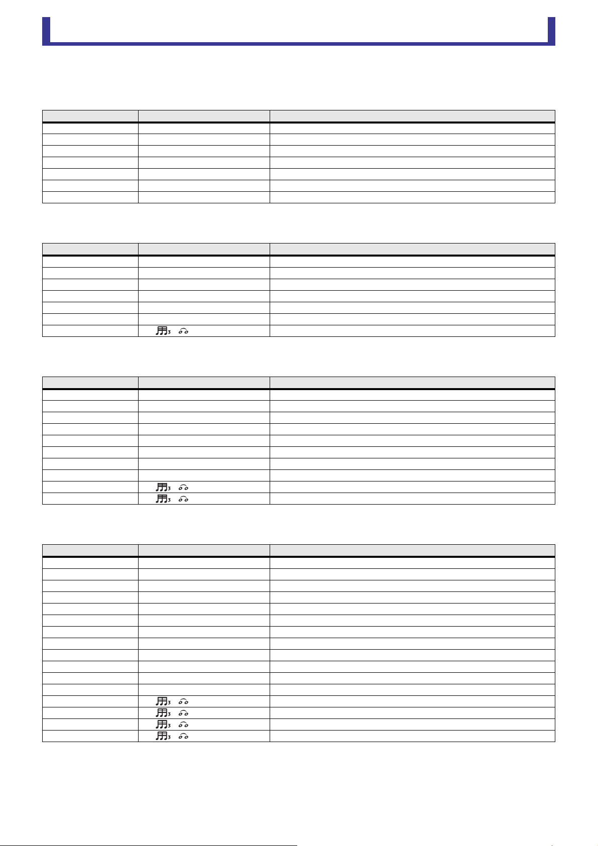
Main display area
User’s Guide
TF Editor
-
57
-
Effect parameters
REVERB HALL, REVERB ROOM, REVERB STAGE, REVERB PLATE
One-input, two-output hall, room, stage, and plate reverbs.
MONO DELAY
One-input, two-output basic repeating-type delay.
STEREO DELAY
Two-input, two-output basic stereo delay.
DELAY LCR
One-input, two-output 3-tap delay.
Parameter Range Description
Reverb Time 0.3s – 20.0s Determines the length of the reverberation.
Initial Delay 1.0ms – 500.0ms Determines the amount of time that passes before the initial reverberation is heard.
High Ratio 0.1 – 1.0 Ratio of high frequency reverberations to the Reverb Time.
Diffusion 0 – 10 Left and right spread of the reverberation.
Density 0% – 100% Density of the reverberation.
HPF Thru, 21.2Hz – 8.00kHz High-pass filter cutoff frequency.
LPF 50.0Hz – 16.0kHz, Thru Low-pass filter cutoff frequency.
Parameter Range Description
Delay 1.0ms – 2700.0ms Delay time.
Feedback Gain -99 – +99 Amount of feedback.
High Ratio 0.1 – 1.0 Amount of high-frequency feedback.
HPF Thru, 21.2Hz – 8.00kHz High-pass filter cutoff frequency.
LPF 50.0Hz – 16.0kHz, Thru Low-pass filter cutoff frequency.
Sync Off, On Delay time tempo sync.
Note ----, – Value used to calculate the delay time based on the tempo.
Parameter Range Description
Delay L 1.0ms – 1350.0ms Left channel delay time.
Delay R 1.0ms – 1350.0ms Right channel delay time.
Feedback Gain L -99 – +99 Left channel feedback gain.
Feedback Gain R -99 – +99 Right channel feedback gain.
High Ratio 0.1 – 1.0 Amount of high-frequency feedback.
HPF Thru, 21.2Hz – 8.00kHz High-pass filter cutoff frequency.
LPF 50.0Hz – 16.0kHz, Thru Low-pass filter cutoff frequency.
Sync Off, On Delay time tempo sync.
Note L ----, – Value used to calculate the left channel delay time based on the tempo.
Note R ----, – Value used to calculate the right channel delay time based on the tempo.
Parameter Range Description
Delay L 1.0ms – 2700.0ms Left channel delay time.
Delay C 1.0ms – 2700.0ms Center channel delay time.
Delay R 1.0ms – 2700.0ms Right channel delay time.
Delay FB 1.0ms – 2700.0ms Feedback delay time.
Feedback Gain -99 – +99 Amount of feedback.
High Ratio 0.1 – 1.0 Amount of high-frequency feedback.
HPF Thru, 21.2Hz – 8.00kHz High-pass filter cutoff frequency.
LPF 50.0Hz – 16.0kHz, Thru Low-pass filter cutoff frequency.
Level L -100 – +100 Left channel level.
Level C -100 – +100 Center channel level.
Level R -100 – +100 Right channel level.
Sync Off, On Delay time tempo sync.
Note L ----, – Value used to calculate the left channel delay time based on the tempo.
Note C ----, – Value used to calculate the center channel delay time based on the tempo.
Note R ----, – Value used to calculate the right channel delay time based on the tempo.
Note FB ----, – Value used to calculate the delay feedback time based on the tempo.
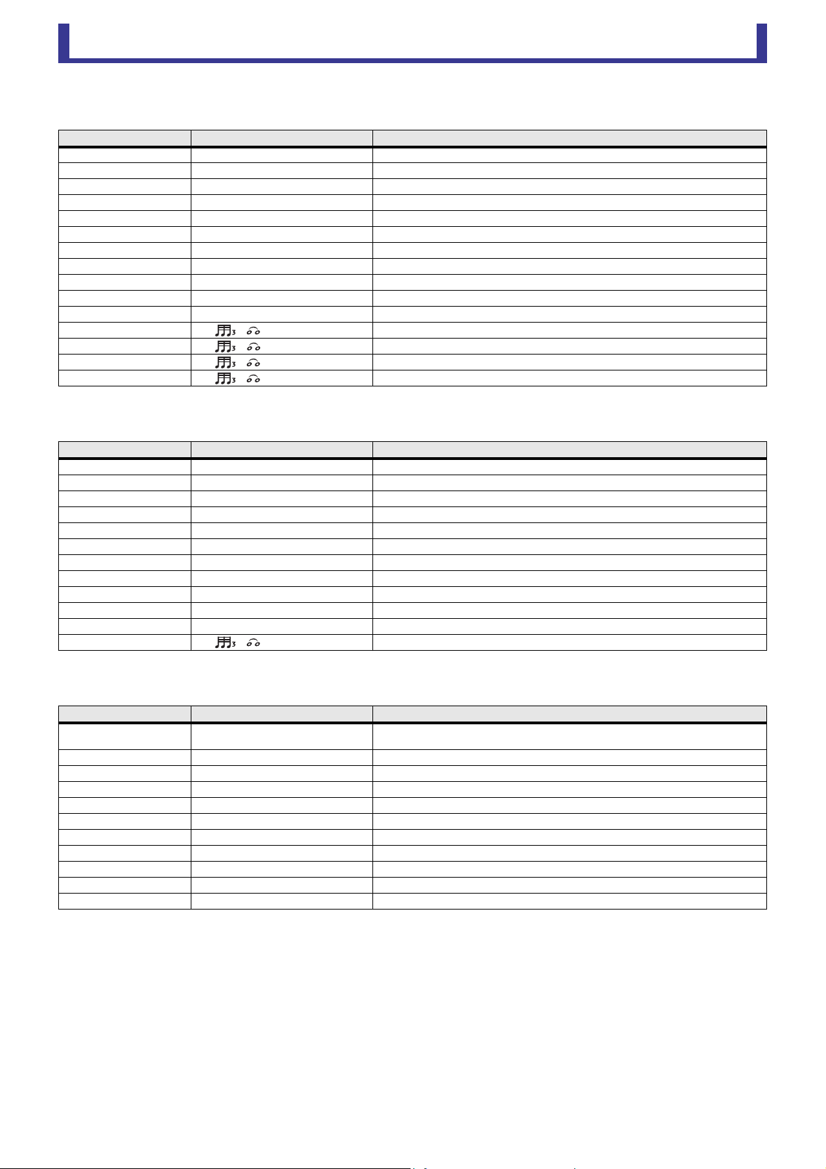
Main display area
User’s Guide
TF Editor
-
58
-
ECHO
Two-input, two-output stereo delay with a crossed feedback loop.
DELAY-REVERB
One-input, two-output effect that has a delay and reverb connected in series.
EARLY REF
One-input, two-output early reflection effect.
Parameter Range Description
Delay L 1.0ms – 1350.0ms Left channel delay time.
Delay R 1.0ms – 1350.0ms Right channel delay time.
Delay FB L 1.0ms – 1350.0ms Left channel feedback delay time.
Delay FB R 1.0ms – 1350.0ms Right channel feedback delay time.
Feedback Gain L -99 – +99 Left channel feedback gain.
Feedback Gain R -99 – +99 Right channel feedback gain.
XFeedback Gain -99 – +99 Left-to-right, right-to-left feedback gain.
High Ratio 0.1 – 1.0 Amount of high-frequency feedback.
HPF Thru, 21.2Hz – 8.00kHz High-pass filter cutoff frequency.
LPF 50.0Hz – 16.0kHz, Thru Low-pass filter cutoff frequency.
Sync Off, On Delay time tempo sync.
Note L ----, – Value used to calculate the left channel delay time based on the tempo.
Note R ----, – Value used to calculate the right channel delay time based on the tempo.
Note FBL ----, – Value used to calculate the left delay feedback time based on the tempo.
Note FBR ----, – Value used to calculate the right delay feedback time based on the tempo.
Parameter Range Description
Delay 1.0ms – 2700.0ms Delay time.
Feedback Gain -99% – 99% Amount of feedback.
DLY BAL 0% – 100% Delay mix balance.
Reverb Time 0.3s – 20.0s Determines the length of the reverberation.
High Ratio 0.1 – 1.0 Ratio of high frequency reverberations to the Reverb Time.
Diffusion 0 – 10 Left and right spread of the reverberation.
Density 0% – 100% Density of the reverberation.
HPF Thru, 21.2Hz – 8.00kHz High-pass filter cutoff frequency.
LPF 50.0Hz – 16.0kHz, Thru Low-pass filter cutoff frequency.
REV BAL 0% – 100% Reverb mix balance.
Sync Off, On Parameter tempo sync.
Note ----, – Value used to calculate the delay time based on the tempo.
Parameter Range Description
Type
S-Hall, L-Hall, Random, Reverse, Plate,
Spring
Early reflection type.
Room Size 0.1 – 20.0 Room size; determines interval between early reflections.
Liveness 0 – 10 Decay of the early reflections (0: least lively; 10: most lively)
Initial Delay 1.0ms – 500.0ms Delay before the early reflection.
Diffusion 0 – 10 Width of the reflections in the stereo field.
Density 0% – 100% Density of the reflections.
ER Number 1 – 19 Number of reflections.
Feedback Gain -99% – 99% Amount of feedback.
High Ratio 0.1 – 1.0 Amount of high-frequency feedback.
HPF Thru, 21.2Hz – 8.00kHz High-pass filter cutoff frequency.
LPF 50.0Hz – 16.0kHz, Thru Low-pass filter cutoff frequency.
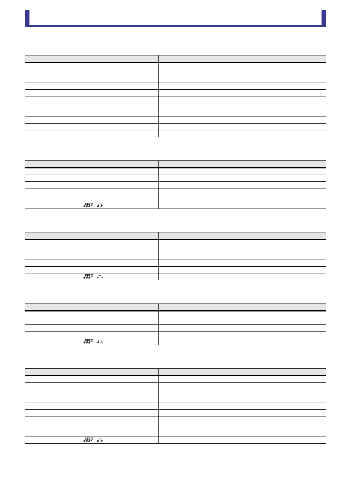
Main display area
User’s Guide
TF Editor
-
59
-
GATE REVERB, REVERSE GATE
One-input, two-output early reflection with gate, and an early reflection with reverse gate.
CHORUS
Two-input, two-output chorus effect.
FLANGE
Two-input, two-output flanger effect.
SYMPHONIC
Two-input, two-output symphonic effect.
PHASER
Two-input, two-output 16-stage phase-shift effect.
Parameter Range Description
Type Type-A, Type-B Early reflection type.
Room Size 0.1 – 20.0 Room size; determines interval between early reflections.
Liveness 0 – 10 Decay of the early reflections
Initial Delay 1.0ms – 500.0ms Delay before the early reflection.
Diffusion 0 – 10 Width of the reflections in the stereo field.
Density 0% – 100% Density of the reflections.
ER Number 1 – 19 Number of reflections.
Feedback Gain -99% – 99% Amount of feedback.
High Ratio 0.1 – 1.0 Amount of high-frequency feedback.
HPF Thru, 21.2Hz – 8.00kHz High-pass filter cutoff frequency.
LPF 50.0Hz – 16.0kHz, Thru Low-pass filter cutoff frequency.
Parameter Range Description
Frequency 0.05Hz – 10.00Hz Modulation speed
AM Depth 0% – 100% Depth of amplitude modulation.
PM Depth 0% – 100% Depth of pitch modulation.
MOD. Delay 1.0ms – 500.0ms Delay time of modulation.
Sync Off, On Parameter tempo sync.
Note – Value used to calculate the frequency based on the tempo.
Parameter Range Description
Frequency 0.05Hz – 10.00Hz Modulation speed
Depth 0% – 100% Depth of modulation.
MOD. Delay 1.0ms – 500.0ms Delay time of modulation.
Feedback Gain -99% – 99% Amount of feedback.
Sync Off, On Parameter tempo sync.
Note – Value used to calculate the frequency based on the tempo.
Parameter Range Description
Frequency 0.05Hz – 10.00Hz Modulation speed
Depth 0% – 100% Depth of modulation.
MOD. Delay 1.0ms – 500.0ms Delay time of modulation.
Sync Off, On Parameter tempo sync.
Note – Value used to calculate the frequency based on the tempo.
Parameter Range Description
Frequency 0.05Hz – 10.00Hz Modulation speed
Depth 0% – 100% Depth of modulation.
Feedback Gain -99% – 99% Amount of feedback.
Offset 0 – 100 Offset of the phase shifted frequency.
Phase 0° – 355° Left/right balance of modulation.
Stage 2 – 16 Number of phase shift stages.
HPF Thru, 21.2Hz – 8.00kHz High-pass filter cutoff frequency.
LPF 50.0Hz – 16.0kHz, Thru Low-pass filter cutoff frequency.
Sync Off, On Parameter tempo sync.
Note – Value used to calculate the frequency based on the tempo.
Main display area
User’s Guide
TF Editor
-
60
-
M BAND COMP
Two-input, two-output three-band compressor. Each band has solo and gain reduction metering.
PING PONG DELAY
One-input, two-output ping pong delay. The delayed sound alternates between left and right at equal intervals.
DUAL PITCH
Two-input, two-output pitch-shift effect.
Parameter Range Description
Low Gain -12.0dB – +12.0dB Low-band gain.
Mid Gain -12.0dB – +12.0dB Mid-band gain.
High Gain -12.0dB – +12.0dB High-band gain.
Total Gain -72dB – +12dB Overall gain.
L-M XOver 21.2Hz – 8.00kHz Low-to-mid crossover frequency.
M-H XOver 21.2Hz – 8.00kHz Mid-to-high crossover frequency.
Knee 0 – 5 Crossover knee (all bands).
Low/Mid/High Link Off, On When turned on, the difference in the threshold for low, mid, and high is maintained.
Low Thr -54dB – 0dB Low threshold.
Low Ratio 1:1 – ∞:1 Low ratio.
Low Attack 0ms – 120ms Low attack time.
Low Release 3.34ms – 42.7s Low release time.
Low Bypass Off, On Compression bypass feature for low.
Low Solo Off, On Solo feature for low.
Mid Thr -54dB – 0dB Mid threshold.
Mid Ratio 1:1 – ∞:1 Mid ratio.
Mid Attack 0ms – 120ms Mid attack time.
Mid Release 3.34ms – 42.7s Mid release time.
Mid Bypass Off, On Compression bypass feature for mid.
Mid Solo Off, On Solo feature for mid.
High Thr -54dB – 0dB High threshold.
High Ratio 1:1 – ∞:1 High Ratio
High Attack 0ms – 120ms High attack time.
High Release 3.34ms – 42.7s High release time.
High Bypass Off, On Compression bypass feature for high.
High Solo Off, On Solo feature for high.
Parameter Range Description
Delay 1.0ms – 1350.0ms Delay time.
Feedback Gain -99% – 99% Amount of feedback.
High Ratio 0.1 – 1.0 Amount of high-frequency feedback.
HPF Thru, 21.2Hz – 8.00kHz High-pass filter cutoff frequency.
LPF 50.0Hz – 16.0kHz, Thru Low-pass filter cutoff frequency.
Sync Off, On Parameter tempo sync.
Note ----, – Value used to calculate the delay time based on the tempo.
Parameter Range Description
Pitch 1 -24 – 24 Pitch of Ch1 (semitone increments).
Fine 1 -50 – 50 Pitch of Ch1 (1 cent increments).
Level 1 -100 – 100 Volume of Ch1.
Pan 1 L63 – R63 Pan of Ch1.
Delay 1 1.0ms – 1000.0ms Delay time of Ch1.
Feedback Gain 1 -99 – 99 Feedback level of Ch1.
Pitch 2 -24 – 24 Pitch of Ch2 (semitone increments).
Fine 2 -50 – 50 Pitch of Ch2 (1 cent increments).
Level 2 -100 – 100 Volume of Ch2.
Pan 2 L63 – R63 Pan of Ch2.
Delay 2 1.0ms – 1000.0ms Delay time of Ch2.
Feedback Gain 2 -99 – 99 Feedback level of Ch2.
Mode 1 – 10 Width of pitch shift.
Sync Off, On Parameter tempo sync.
Note 1 ----, – Value used to calculate Delay 1 based on the tempo.
Note 2 ----, – Value used to calculate Delay 2 based on the tempo.

Main display area
User’s Guide
TF Editor
-
61
-
OUTPUT DELAY
Two-input, two-output single delay. When used for INS FX 1–6, this delay is good for delay compensation.
*1 frame rate=24: 0.03 - 24.00,
frame rate=25: 0.03 - 25.00,
frame rate=29.97D/29.97: 0.03 - 29.97
frame rate=30D/30: 0.03 - 30.00
Set the frame rate from the Menu bar Setup menu Frame Rate.
Parameter Range Description
LR LINK On, Off Links the left and right delays.
Delay
0.3 – 343.6 meter
1.1 – 1127.3 feet
1.00 – 1000.00ms
0.03 – 30.00 frame
*1
Sets the delay time in frames, meters, feet, or ms (milliseconds).
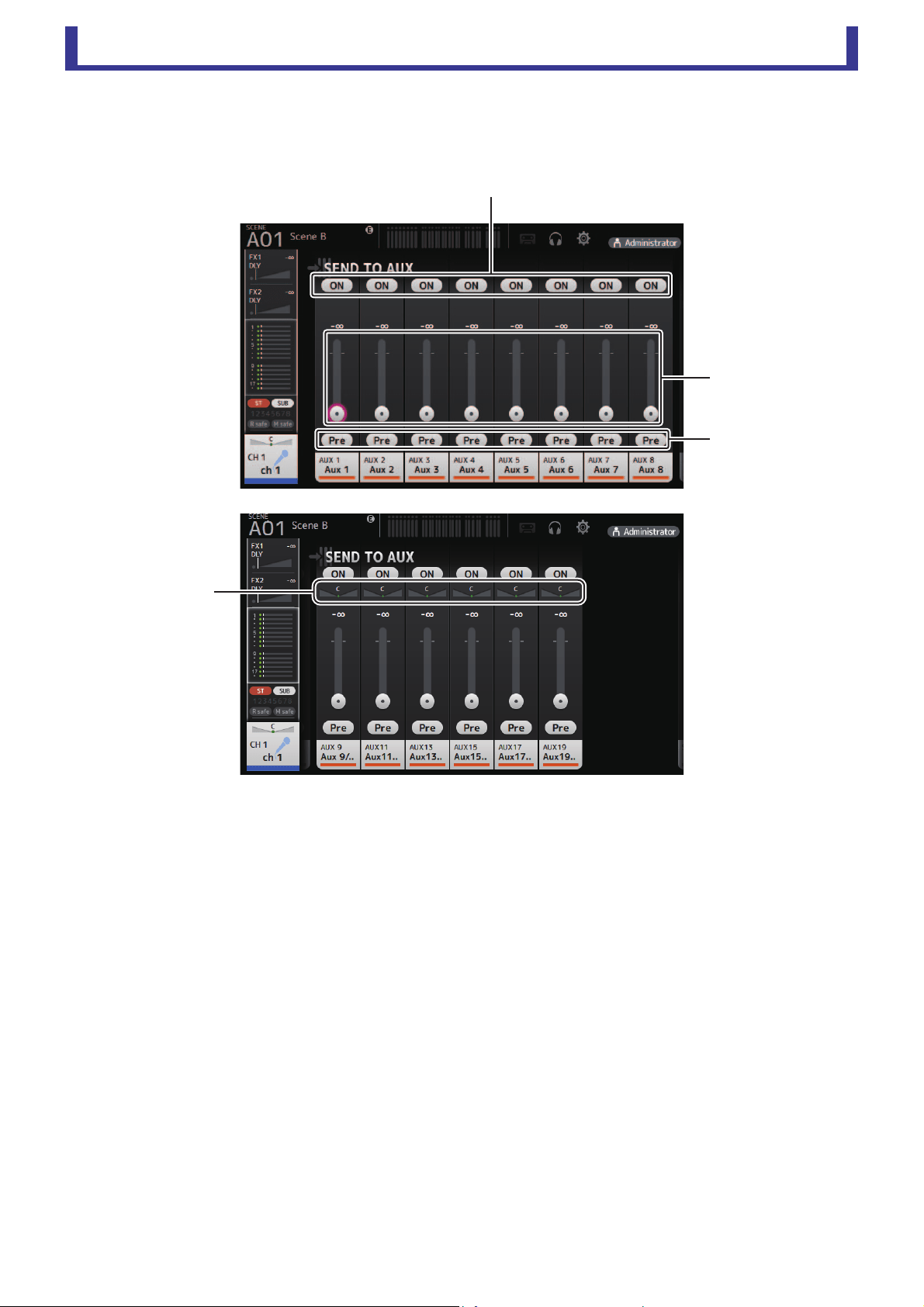
Main display area
User’s Guide
TF Editor
-
62
-
SEND TO AUX screen
Allows you to configure the amount of signal from each channel is sent to the AUX buses.
You can drag left and right to view other buses.
1 Send button
Determines whether a signal is sent (on) or not sent (off) to the corresponding AUX bus.
2 Send level slider
Determines the amount of signal sent to the corresponding AUX bus.
3 Pre button
Selects whether to send the signal to the AUX channel from before the fader, or from after the fader.
On: Before the fader
Off: After the fader
4 Send pan slider
Displayed for stereo AUX buses. Allows you to adjust the pan of the signal sent to the AUX bus.
ձ
ղ
ճ
մ
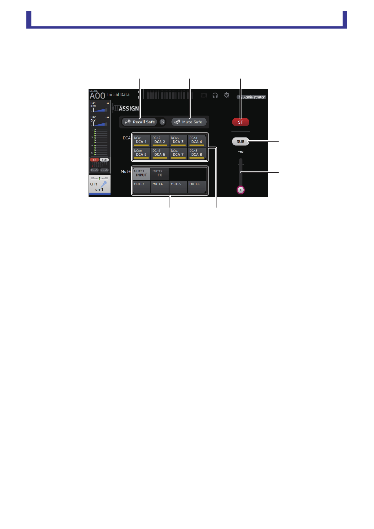
Main display area
User’s Guide
TF Editor
-
63
-
ASSIGN screen
Allows you configure recall safe and mute safe settings, DCA group assignments, signals sent to the SUB bus, etc. for each
channel.
1 Recall Safe button
Turns Recall Safe on and off for the corresponding channel.
You can display the RECALL SAFE screen by clicking the jump button in the right corner of the Recall Safe button (page 22).
2 Mute Safe button
You can temporarily exclude certain channels from a mute group.
If you mute a mute group, any channels in that group that have mute safe enabled will not be muted.
3 ST button
Turns the channel's assignment to the stereo channel on and off.
4 SUB button
Determines whether the channel's signal is sent (on) or not sent (off) to the SUB bus.
5 SUB level slider
Determines the amount of signal sent from the selected channel to the SUB bus.
6 DCA buttons
Turns the channel's assignment to each DCA group (1–8) on and off.
You can assign a channel to multiple DCA groups if desired.
7 Mute buttons
Turns the channel's assignment to mute groups 3–6 on and off.
You can assign a channel to multiple mute groups if desired.
You cannot change the assignments for MUTE1 INPUT and MUTE2 FX.
ձ ղ
ն
ճ
մ
յ
շ
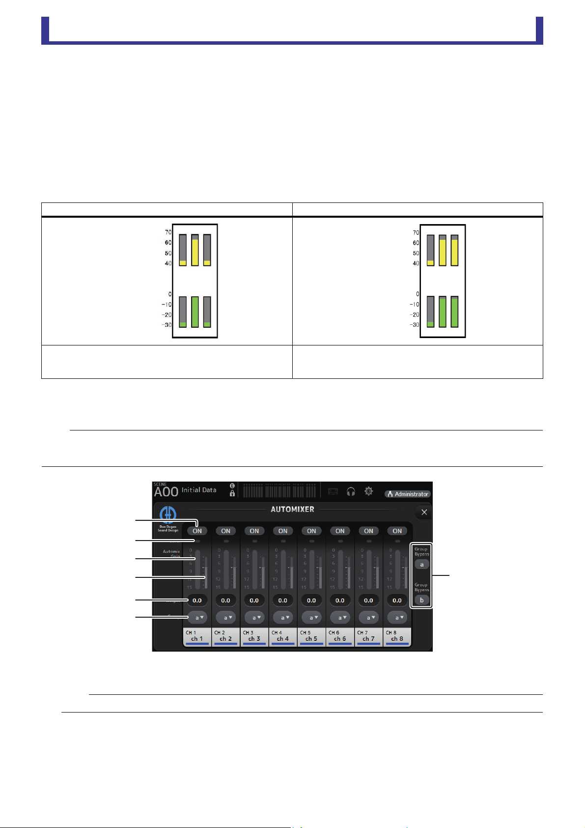
Main display area
User’s Guide
TF Editor
-
64
-
AUTOMIXER screen
Sets the AUTOMIXER that can be used for CH1–CH8.
About the AUTOMIXER
The AUTOMIXER is a function for automating the sound mixing of conversation heard in conferences, talk shows and so on. This
function detects mics that are enabled and automatically optimizes the gain distribution to maintain a consistent system gain with
multiple mics, eliminating the need for the engineer to keep watching the fader levels.
How the AUTOMIXER works
The TF series AUTOMIXER uses the Dugan speech system, which automatically adjusts the gain of up to 8 mics.
Unlike limiters or auto-level controllers, the Dugan speech system lets the engineer control individual levels as usual, even when
more than one person is talking at the same time. Also, the audio on the mics is detected and the gain is automatically distributed
when no one is talking, so the faders can be left up.
1 AUTOMIXER ON button
Turns the AUTOMIXER on/off for the respective channel.
When one person speaks, while using multiple mics When two people speak, while using multiple mics
When one person talks, the gain on that mic instantly rises, and the
gain on other mics is lowered. This works the same when another
person speaks.
When two people talk at the same time, the gain between the two mics
is automatically distributed to provide a uniform total gain, and the gain
on the remaining mic is lowered.
NOTE
• The AUTOMIXER is placed directly after the channel ON for CH1–CH8.
• When the Pre button for SEND TO AUX on CH1–CH8 is off, signal is sent from directly after the AUTOMIXER to the AUX bus.
• When CH1–CH8 are stereo linked together, the AUTOMIXER parameters will not be linked.
NOTE
We recommend that you leave the AUTOMIXER off for audio that does not contain speech components, such as live concerts.
Mic input
audio (dB)
Automix gain
(dB)
Mic input
audio (dB)
Automix gain
(dB)
ձ
ղ
ճ
մ
յ
ն
շ

Main display area
User’s Guide
TF Editor
-
65
-
2 Level indicator
Use this indicator to check whether the input gain going into the AUTOMIXER is appropriate.
Off: No input signal, or not enough input level
Lighted green: Input gain is appropriate
Lighted red:Overload input
3 Automix gain meter
Displays the gain that was adjusted using the AUTOMIXER.
4 Weight indicator
Displays the value that was set in the 5 Weight text box as a bar graph.
5 Weight text box
Adjusts the signal level inputted into the AUTOMIXER side chain. When this is set to the same value as other channels, the
gain of audio signals that are inputted at the same time will be equally distributed. When this value is increased, the gain of
audio signals that are inputted at the same time will be distributed to create a louder sound compared with other channels.
Setting range: -100.0 dB, -29.5 dB–0.0 dB (default setting)–15.0 dB
6 Group selection button
Selects whether to assign either AUTOMIXER group a or b. You can use groups to independently create two types of mixes.
The background color changes according to the group selected.
7 Group Bypass a/b buttons
Turns the Automixer function bypass on/off for each group.
NOTE
Adjust the input gain using the analog gain, digital gain and faders for each input channel.
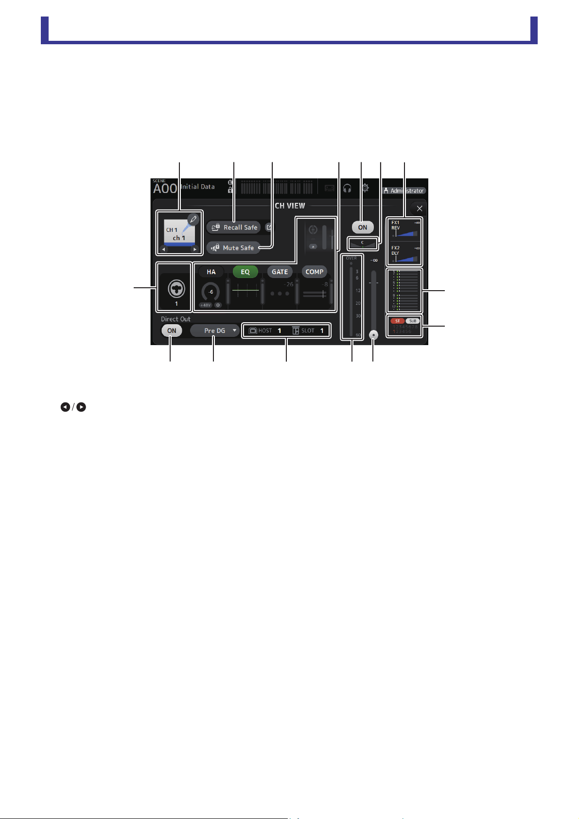
Main display area
User’s Guide
TF Editor
-
66
-
CH VIEW screen
Provides an overview of all the settings for a channel.
You can change settings using this screen, in addition to the corresponding feature's configuration screen. Items displayed on this
screen vary depending on the type of channel selected.
CH1–CH32
1 Channel name
Click to display the CH NAME screen (page 78).
Click to display information for a different channel.
2 Recall Safe button
Turns Recall Safe on and off for the corresponding channel.
You can display the RECALL SAFE screen by clicking the jump button in the right corner of the Recall Safe button.
3 Input source indicator
Displays the input channel's input source. You can select the input source on the INPUT screen.
4 Mute Safe button
Click to temporarily exclude the selected channel from the input mute group.
If you mute the input mute group, any channels in that group that have mute safe enabled will not be muted.
5 HA/EQ/GATE/COMP boxes
Click to display the configuration screen for the corresponding feature.
You can click the EQ, GATE, and COMP buttons displayed here to turn the corresponding feature on and off.
HA box: Displays the INPUT screen (page 45).
EQ box: Displays the EQ screen (page 48).
GATE box: Displays the GATE screen (page 51).
COMP box: Displays the COMP screen (page 53).
AUTOMIXER box (CH1–CH8 only): Displays the AUTOMIXER screen (page 64).
6 Channel on/off button
Turns the selected channel on and off.
7 Channel pan slider
Adjusts the pan for the selected channel.
8 FX1/FX2 boxes
Displays the effect type.
When selected, you can use the mouse wheel to adjust the effects send level. You can also display the corresponding effect's
configuration screen by clicking again.
Each box displays the amount of signal from the selected channel that is sent to the corresponding effects module.
Send level, the selected channel's fader level, and the actual send level grouped with the DCA is displayed in the triangular bar.
Displays whether the signal sent to the FX1/2 return channel is from directly before the fader, or directly after the fader. If the
indicator lights green, the signal is directly before (pre-fader); and if the indicator is off, the signal is directly after (post-fader).
չ
պ
ջռսվտ
ճ
ձղմ յնո
շ
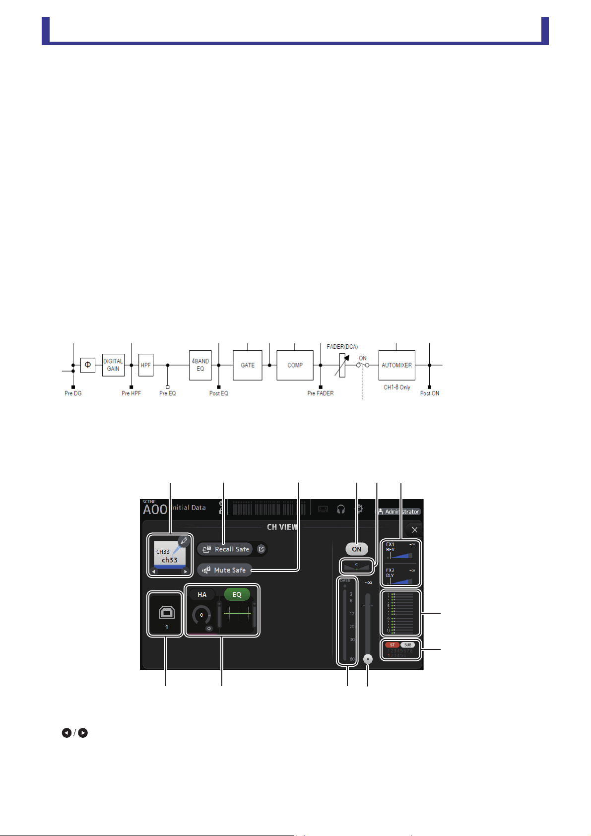
Main display area
User’s Guide
TF Editor
-
67
-
9 SEND TO AUX box
Click when selected to display the SEND TO AUX screen.
Displays the amount of signal from the selected channel that is sent to each AUX bus.
Send level, the selected channel's fader level, and the actual send level grouped with the DCA is displayed in the horizontal
bar.
The information displayed here indicates whether the signal sent to the AUX bus is the pre-fader or post-fader signal. Pre-
fader signal is displayed in green; post-fader signal is displayed in gray.
0 ASSIGN box
Displays the ASSIGN screen (page 63).
A Channel output level slider
Adjusts the fader level for the selected channel.
B Channel output level meter
Displays the output level for the selected channel.
C Direct out port indicator
Indicates the channel's direct out port (i.e., output jack).
D Direct out point button
Allows you to set the point of the direct out signal.
Pre DG: Before the digital gain
Pre HPF: Before the high-pass filter
Pre Fader: Before the fader
Post ON: directly after the [ON] key; CH1–CH8 are directly after the AUTOMIXER
E Direct out on/off button
Turns the direct out on and off.
CH33–CH40
1 Channel name
Click to display the CH NAME screen (page 78).
Click to display information for a different channel.
2 Recall Safe button
Turns Recall Safe on and off for the corresponding channel.
You can display the RECALL SAFE screen by clicking the jump button in the right corner of the Recall Safe button.
ձղ մ նշո
չ
պ
ջռյճ

Main display area
User’s Guide
TF Editor
-
68
-
3 Input source indicator
Displays the input channel's input source. You can select the input source on the INPUT screen.
4 Mute Safe button
Click to temporarily exclude the selected channel from the input mute group.
If you mute the input mute group, any channels in that group that have mute safe enabled will not be muted.
5 HA/EQ boxes
Click to display the configuration screen for the corresponding feature.
You can click the EQ button displayed here to turn EQ on and off.
HA box: Displays the INPUT screen (page 45).
EQ box: Displays the EQ screen (page 48).
6 Channel on/off button
Turns the selected channel on and off.
7 Channel pan slider
Adjusts the pan for the selected channel.
8 FX1/FX2 boxes
Displays the effect type.
When selected, you can use the mouse wheel to adjust the effects send level. You can also display the corresponding effect's
configuration screen by clicking again.
Each box displays the amount of signal from the selected channel that is sent to the corresponding effects module.
Send level, the selected channel's fader level, and the actual send level grouped with the DCA is displayed in the triangular bar.
Displays whether the signal sent to the FX1/2 return channel is from directly before the fader, or directly after the fader. If the
indicator lights green, the signal is directly before (pre-fader); and if the indicator is off, the signal is directly after (post-fader).
9 SEND TO AUX box
Click when selected to display the SEND TO AUX screen.
Displays the amount of signal from the selected channel that is sent to each AUX bus.
Send level, the selected channel's fader level, and the actual send level grouped with the DCA is displayed in the horizontal
bar.
The information displayed here indicates whether the signal sent to the AUX bus is the pre-fader or post-fader signal. Pre-
fader signal is displayed in green; post-fader signal is displayed in gray.
0 ASSIGN box
Displays the ASSIGN screen (page 63).
A Channel output level slider
Adjusts the fader level for the selected channel.
B Channel output level meter
Displays the output level for the selected channel.
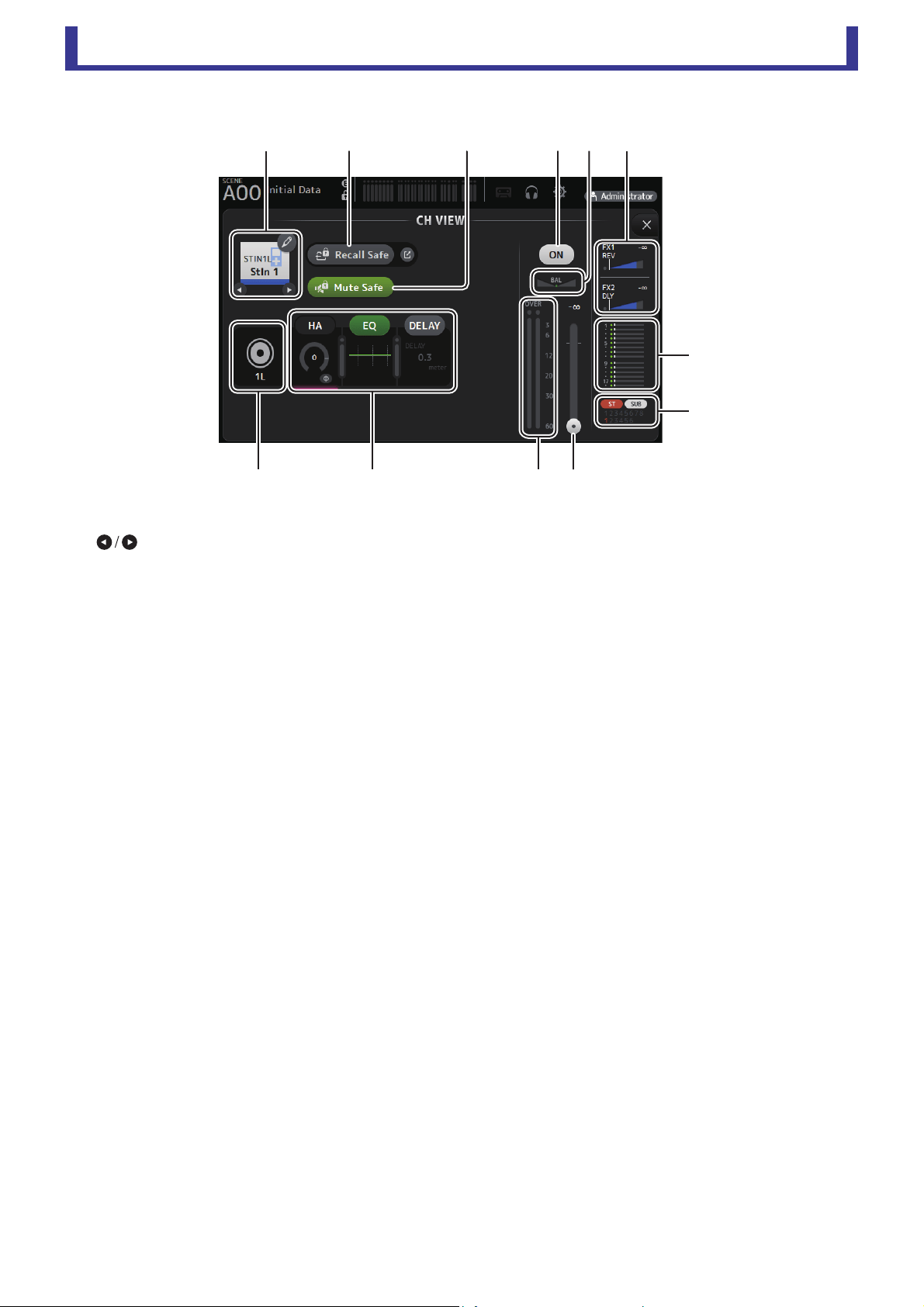
Main display area
User’s Guide
TF Editor
-
69
-
ST IN 1L-ST IN 2R
1 Channel name
Click to display the CH NAME screen (page 78).
Click to display information for a different channel.
2 Recall Safe button
Turns Recall Safe on and off for the corresponding channel.
You can display the RECALL SAFE screen by clicking the jump button in the right corner of the Recall Safe button.
3 Input source indicator
Displays the input channel's input source. You can select the input source on the INPUT screen.
4 Mute Safe button
Click to temporarily exclude the selected channel from the input mute group.
If you mute the input mute group, any channels in that group that have mute safe enabled will not be muted.
5 HA/EQ boxes
Click to display the configuration screen for the corresponding feature.
You can click the EQ button displayed here to turn EQ on and off.
HA box: Displays the INPUT screen (page 45).
EQ box: Displays the EQ screen (page 48).
DELAY box: Displays the DELAY screen (page 84).
6 Channel on/off button
Turns the selected channel on and off.
7 BAL (balance) slider
Adjusts the left/right volume balance for the channel.
8 FX1/FX2 boxes
Displays the effect type.
When selected, you can use the mouse wheel to adjust the effects send level. You can also display the corresponding effect's
configuration screen by clicking again.
Each box displays the amount of signal from the selected channel that is sent to the corresponding effects module.
Send level, the selected channel's fader level, and the actual send level grouped with the DCA is displayed in the triangular bar.
Displays whether the signal sent to the FX1/2 return channel is from directly before the fader, or directly after the fader. If the
indicator lights green, the signal is directly before (pre-fader); and if the indicator is off, the signal is directly after (post-fader).
9 SEND TO AUX box
Click when selected to display the SEND TO AUX screen.
Displays the amount of signal from the selected channel that is sent to each AUX bus.
Send level, the selected channel's fader level, and the actual send level grouped with the DCA is displayed in the horizontal
bar.
The information displayed here indicates whether the signal sent to the AUX bus is the pre-fader or post-fader signal. Pre-
fader signal is displayed in green; post-fader signal is displayed in gray.
ձղ մ նշո
չ
պ
ջռյճ
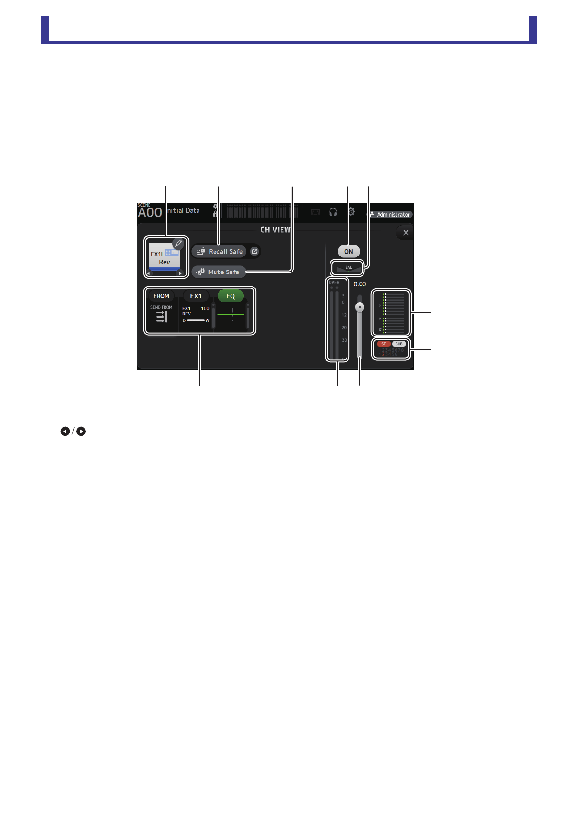
Main display area
User’s Guide
TF Editor
-
70
-
0 ASSIGN box
Displays the ASSIGN screen (page 63).
A Channel output level slider
Adjusts the fader level for the selected channel.
B Channel output level meter
Displays the output level for the selected channel.
FX1L–FX2R
1 Channel name
Click to display the CH NAME screen (page 78).
Click to display information for a different channel.
2 Recall Safe button
Turns Recall Safe on and off for the corresponding channel.
You can display the RECALL SAFE screen by clicking the jump button in the right corner of the Recall Safe button.
3 Mute Safe button
Click to temporarily exclude the selected channel from the effects mute group. If you mute the effects mute group, any
channels in that group that have mute safe enabled will not be muted.
4 FROM/FX/EQ boxes
Click to display the configuration screen for the corresponding feature.
You can click the EQ button displayed here to turn EQ on and off.
FROM box: Displays the SEND FROM screen (page 82).
FX box: Displays the FX screen (page 55).
EQ box: Displays the EQ screen (page 48).
5 Channel on/off button
Turns the selected channel on and off.
6 BAL (balance) slider
Adjusts the left/right volume balance for the channel.
7 SEND TO AUX box
Click when selected to display the SEND TO AUX screen.
Displays the amount of signal from the selected channel that is sent to each AUX bus.
Send level, the selected channel's fader level, and the actual send level grouped with the DCA is displayed in the horizontal
bar.
The information displayed here indicates whether the signal sent to the AUX bus is the pre-fader or post-fader signal. Pre-
fader signal is displayed in green; post-fader signal is displayed in gray.
8 ASSIGN box
Displays the ASSIGN screen (page 63).
ձղ ճ յն
շ
ո
չպմ
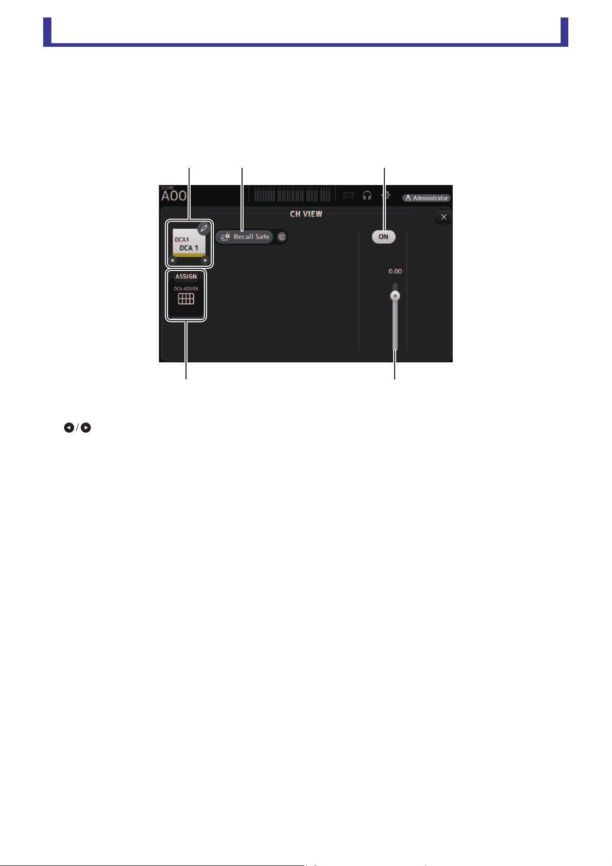
Main display area
User’s Guide
TF Editor
-
71
-
9 Channel output level slider
Adjusts the fader level for the selected channel.
0 Channel output level meter
Displays the output level for the selected channel.
DCA1–DCA8
1 Channel name
Click to display the CH NAME screen (page 78).
Click to display information for a different channel.
2 Recall Safe button
Turns Recall Safe on and off for the corresponding channel.
You can display the RECALL SAFE screen by clicking the jump button in the right corner of the Recall Safe button.
3 Channel on/off button
Turns the selected channel on and off.
4 Channel output level slider
Adjusts the fader level for the selected channel.
5 ASSIGN box
Click when selected to display the DCA ASSIGN screen (page 83).
ձղ ճ
մ
յ
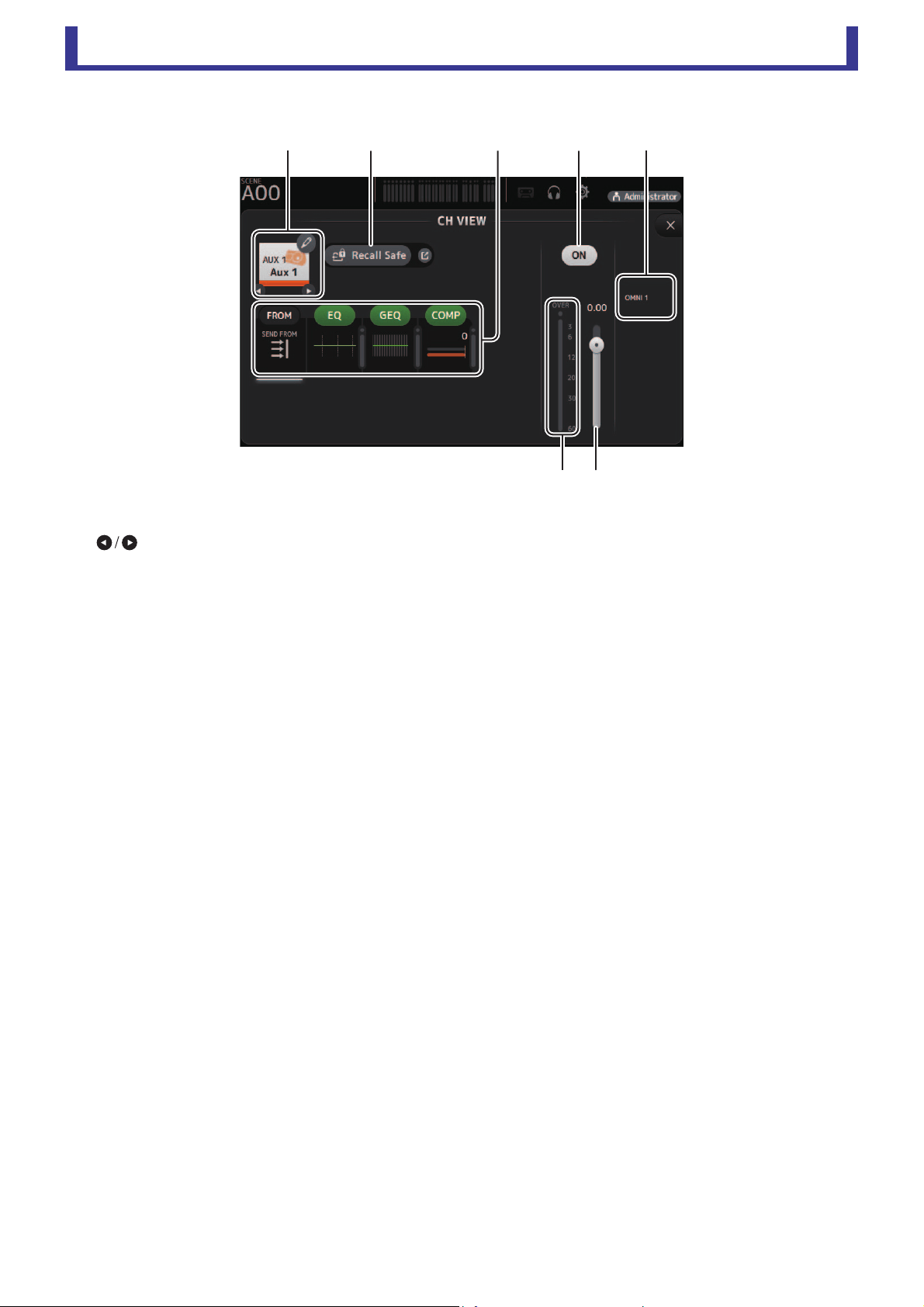
Main display area
User’s Guide
TF Editor
-
72
-
AUX 1–AUX 8
1 Channel name
Click to display the CH NAME screen (page 78).
Click to display information for a different channel.
2 Recall Safe button
Turns Recall Safe on and off for the corresponding channel.
You can display the RECALL SAFE screen by clicking the jump button in the right corner of the Recall Safe button.
3 FROM/EQ/GEQ/COMP boxes
Click to display the configuration screen for the corresponding feature.
You can click the EQ, GEQ, and COMP buttons displayed here to turn the corresponding feature on and off.
FROM box: Displays the SEND FROM screen (page 82).
EQ box: Displays the EQ screen (page 48).
GEQ box: Displays the GEQ screen (page 79).
COMP box: Displays the COMP screen (page 53).
4 Channel on/off button
Turns the selected channel on and off.
5 OUTPUT box
Displays the OUTPUT screen (page 81).
6 Channel output level slider
Adjusts the fader level for the selected channel.
7 Channel output level meter
Displays the output level for the selected channel.
ձղ մյ
նշ
ճ
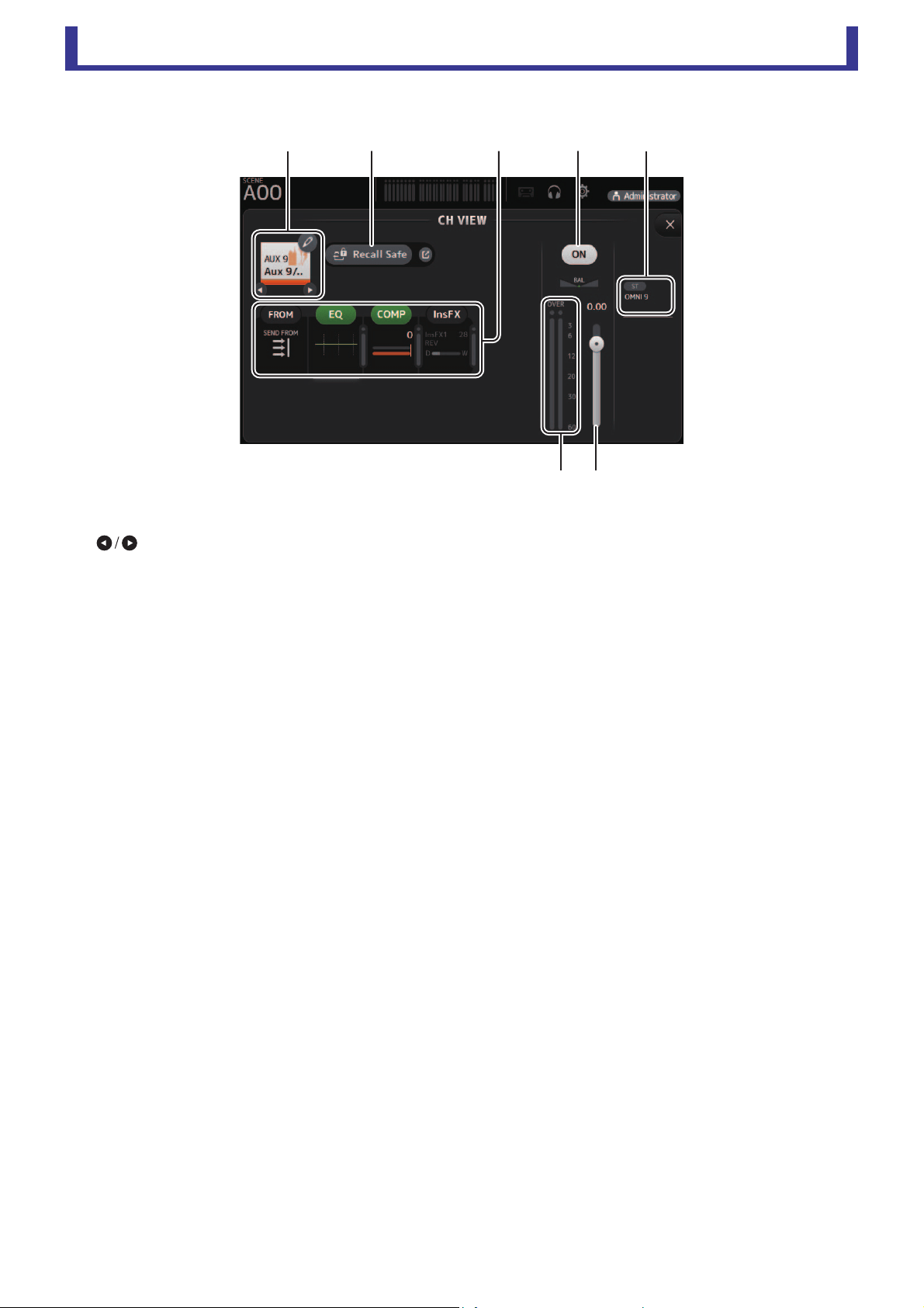
Main display area
User’s Guide
TF Editor
-
73
-
AUX 9–AUX 20
1 Channel name
Click to display the CH NAME screen (page 78).
Click to display information for a different channel.
2 Recall Safe button
Turns Recall Safe on and off for the corresponding channel.
You can display the RECALL SAFE screen by clicking the jump button in the right corner of the Recall Safe button.
3 FROM/EQ/COMP/InsFX boxes
Click to display the configuration screen for the corresponding feature.
You can click the EQ and COMP buttons displayed here to turn the corresponding feature on and off.
FROM box: Displays the SEND FROM screen (page 82).
EQ box: Displays the EQ screen (page 48).
COMP box: Displays the COMP screen (page 53).
InsFX box: Displays the FX screen (page 55).
4 Channel on/off button
Turns the selected channel on and off.
5 OUTPUT box
Displays the OUTPUT screen (page 81).
6 Channel output level slider
Adjusts the fader level for the selected channel.
7 Channel output level meter
Displays the output level for the selected channel.
ձղ մյ
նշ
ճ
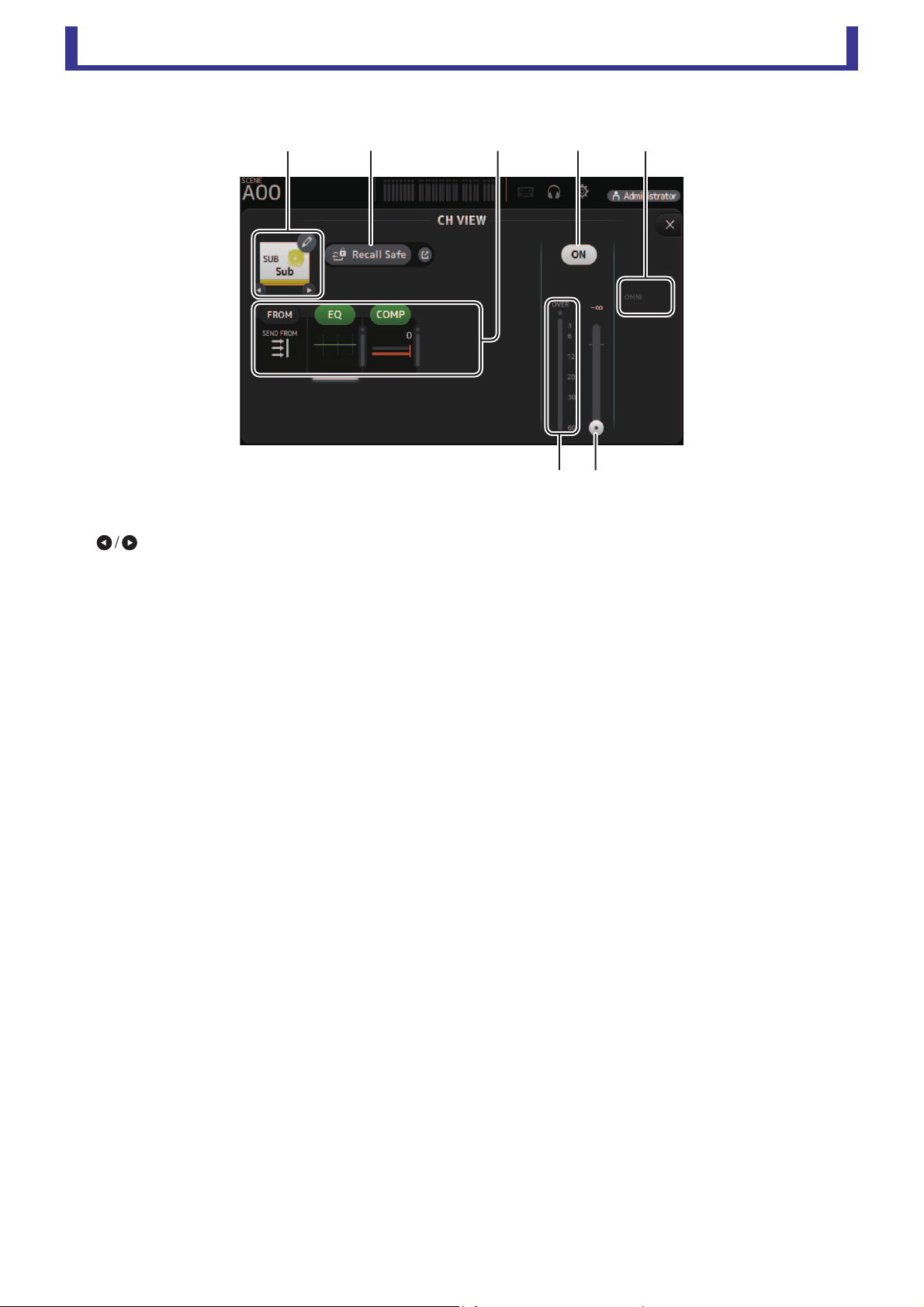
Main display area
User’s Guide
TF Editor
-
74
-
SUB
1 Channel name
Click to display the CH NAME screen (page 78).
Click to display information for a different channel.
2 Recall Safe button
Turns Recall Safe on and off for the corresponding channel.
You can display the RECALL SAFE screen by clicking the jump button in the right corner of the Recall Safe button.
3 FROM/EQ/COMP boxes
Click to display the configuration screen for the corresponding feature.
You can click the EQ and COMP buttons displayed here to turn the corresponding feature on and off.
FROM box: Displays the SEND FROM screen (page 82).
EQ box: Displays the EQ screen (page 48).
COMP box: Displays the COMP screen (page 53).
4 Channel on/off button
Turns the selected channel on and off.
5 OUTPUT box
Displays the OUTPUT screen (page 81).
6 Channel output level slider
Adjusts the fader level for the selected channel.
7 Channel output level meter
Displays the output level for the selected channel.
ձղ մյճ
նշ
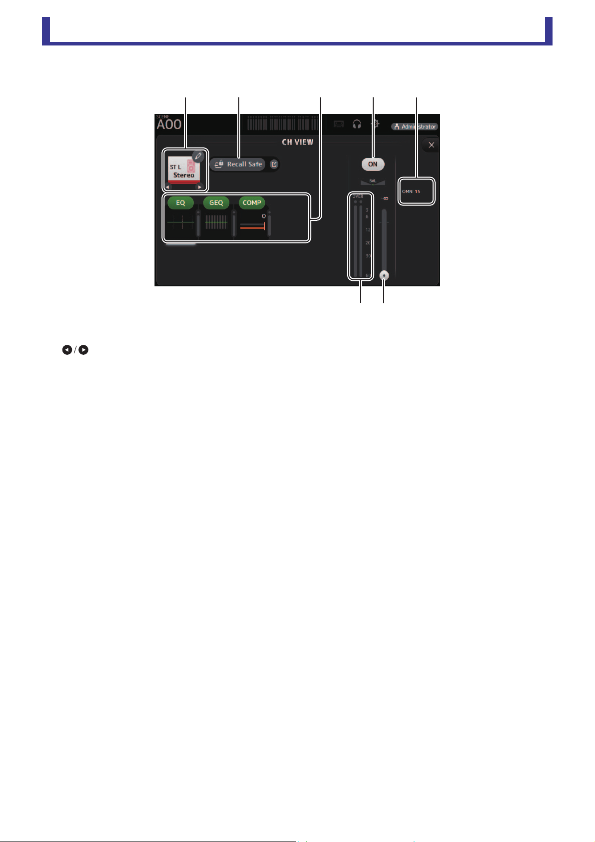
Main display area
User’s Guide
TF Editor
-
75
-
ST L, ST R
1 Channel name
Click to display the CH NAME screen (page 78).
Click to display information for a different channel.
2 Recall Safe button
Turns Recall Safe on and off for the corresponding channel.
You can display the RECALL SAFE screen by clicking the jump button in the right corner of the Recall Safe button.
3 FROM/EQ/GEQ/COMP boxes
Click to display the configuration screen for the corresponding feature.
You can click the EQ, GEQ, and COMP buttons displayed here to turn the corresponding feature on and off.
FROM box: Displays the SEND FROM screen (page 82).
EQ box: Displays the EQ screen (page 48).
GEQ box: Displays the GEQ screen (page 79).
COMP box: Displays the COMP screen (page 53).
4 Channel on/off button
Turns the selected channel on and off.
5 OUTPUT box
Displays the OUTPUT screen (page 81).
6 Channel output level slider
Adjusts the fader level for the selected channel.
7 Channel output level meter
Displays the output level for the selected channel.
շ
ձղ մյ
ն
ճ

Main display area
User’s Guide
TF Editor
-
76
-
MATRIX1– MATRIX4
1 Channel name
Click to display the CH NAME screen.
Click to display information for a different channel.
2 Recall Safe button
Turns recall safe on and off for the corresponding channel.
You can display the RECALL SAFE screen (page 22) by clicking the jump button in the right corner of the Recall Safe button.
3 FROM/EQ/DELAY boxes
Click to display the configuration screen for the corresponding feature.
You can click the EQ and DELAY buttons displayed here to turn the corresponding feature on and off.
FROM box: Displays the SEND FROM screen (page 82).
EQ box: Displays the EQ screen (page 48).
DELAY box: Displays the DELAY screen (page 84).
4 Channel on/off button
Turns the selected channel on and off.
5 OUTPUT box
Displays the OUTPUT screen (page 81).
6 Channel output level slider
Adjusts the fader level for the selected channel.
7 Channel output level meter
Displays the channel's output signal level.
ձղ մյ
նշ
ճ
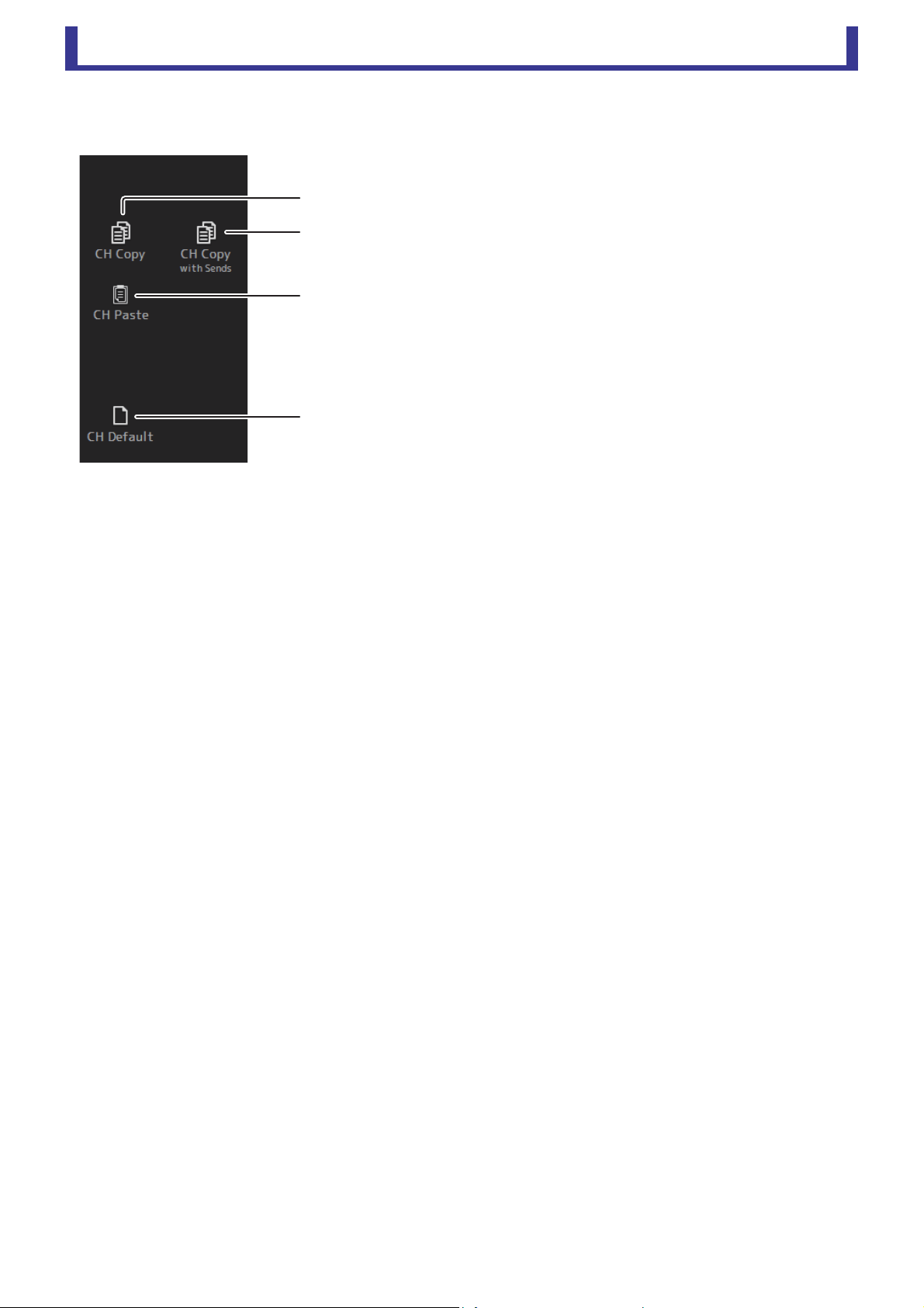
Main display area
User’s Guide
TF Editor
-
77
-
CH VIEW screen menu
The following items are displayed in the menu area when the CH VIEW screen is displayed.
1 CH Copy
Copies the settings of the current channel.
2 CH Copy with Sends
Copies settings from the selected AUX/MATRIX channel, as well as the settings
sent from the sends of each channel.
3 CH Paste / CH Paste with Sends
Pastes the channel settings copied using CH Copy or the settings that were copied
using CH Copy with Send, and applies them to the selected channel.
4 CH Default
Resets the settings of the current channel to their default values.
ղ
ճ
ձ
մ

Main display area
User’s Guide
TF Editor
-
78
-
CH NAME screen
Allows you to set the channel name, icon, and channel color.
1 Name text box
Enter the channel name here.
Click the text box to enter the name using your computer keyboard.
2 Icon button
Click to display a list of available channel icons.
3 Category button
Allows you to select a different category of channel icons.
The available categories vary depending on the type of channel.
4 Channel icon list
Click to apply the channel icon.
You can drag this area up and down to display all of the available icons.
5 Sample Name button
Displays a list of commonly used channel names based on the selected channel icon.
Click on a sample name to use it as the channel name.
6 Color button
Click to display a list of available channel colors.
Click the desired color to use that color as the channel color.
ն
ղ
ձ
ճ
մ
յ
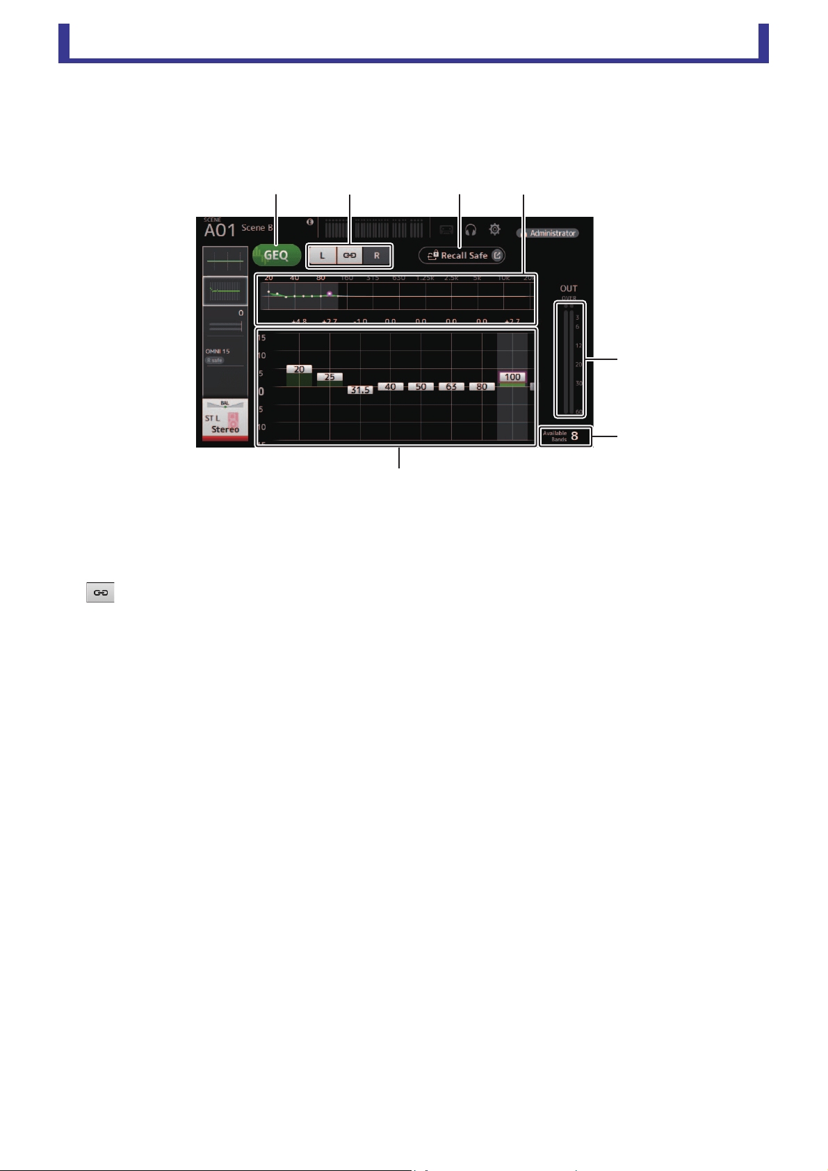
Main display area
User’s Guide
TF Editor
-
79
-
GEQ screen
You can use the internal graphic equalizer (GEQ) to process AUX 1–8 and STEREO channel signals.
The GEQ is a mono, 12-band EQ. Each band is 1/3 octave wide, with an adjustable gain range of ±15 db.
31 bands are available; you can adjust gain for up to 12 bands.
1 GEQ button
Turns the GEQ on and off.
2 GEQ channel selection buttons
These buttons are displayed only when configuring the GEQ for stereo AUX buses or the STEREO channels.
They are not displayed for mono AUX buses.
: Turns the GEQ left/right channel link on and off.
L/R: Allows you select the left and right GEQ channels.
3 Recall Safe button
Displays the RECALL SAFE screen (page 22).
4 EQ graph, band selection
Displays the EQ settings.
Drag left or right or click an area to display the gain sliders for other bands.
5 Gain sliders
Adjusts the gain for the corresponding band.
Drag left or right to display the gain sliders for other bands.
6 Output level meter
Displays the GEQ output level.
7 Available bands display
Displays the number of additional bands that you can adjust.
ձղ ճմ
յ
ն
շ

Main display area
User’s Guide
TF Editor
-
80
-
GEQ screen menu
The following items are displayed in the menu area when the GEQ screen is displayed.
1 Copy
Copies the GEQ parameters of the selected channel to the clipboard.
2 Paste
Pastes the GEQ parameters in the clipboard to the selected channel.
3 Compare
Allows you to compare the GEQ parameters of the selected channel with the GEQ
parameters in the clipboard by switching between the two.
4 Default
Resets all GEQ settings to their default values.
ձ
ղ
ճ
մ
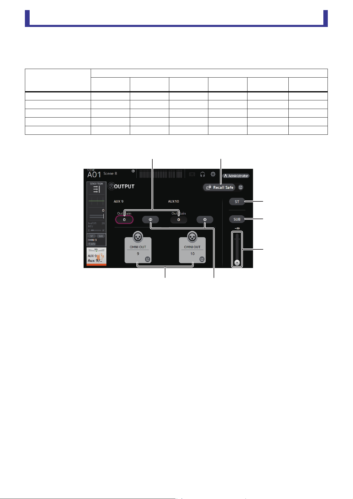
Main display area
User’s Guide
TF Editor
-
81
-
OUTPUT screen
Allows you to select the signals sent to the output channels (OMNI OUT 1–16).
The buttons displayed vary depending on the type of output channel selected.
○: Displayed
–: Not displayed
1 ST button
Determines whether the stereo channel is output or not.
2 SUB button
Determines whether the channel's signal is sent (on) or not sent (off) to the SUB bus.
3 SUB slider
Determines the amount of signal sent from the selected channel to the SUB bus.
4 Out Gain text box
Allows you to adjust the output gain.
When selected, you can use the mouse wheel to adjust the setting. Click again to use your computer keyboard to enter a
value.
5 Φ (phase) button
Allows you to reverse the phase.
When turned on, the output signal's phase is reversed.
6 OMNI OUT button
Displays the number of the OMNI OUT to which the channel is directed.
Up to two numbers can be displayed. For three or more numbers, "+" is displayed.
Displays the OMNI OUT screen (page 21).
7 Recall Safe button
Turns Recall Safe on and off for the corresponding channel.
You can display the RECALL SAFE screen (page 22) by clicking the jump button in the right corner of the Recall Safe button.
Output channel type
Buttons
ST button
SUB button
SUB slider
Out Gain
buttons
Φ button
OMNI OUT
indicator
OMNI OUT
buttons
AUX 1–8 – –
○○ ○ ○
AUX9/10–AUX19/20 ○○○○ ○ ○
SUB – – ○○ ○ ○
STEREO – – ○○ ○ ○
MATRIX1–4 – – ○○ ○ ○
մ
ճ
ձ
ղ
շ
յն
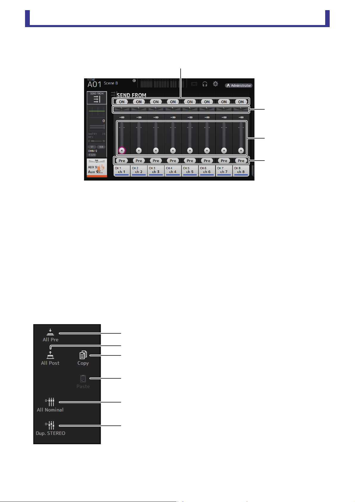
Main display area
User’s Guide
TF Editor
-
82
-
SEND FROM screen
Allows you to send signals from the each channels.
1 ON button
Determines whether a signal is sent (on) or not sent (off) from the corresponding each channel.
2 Send pan slider
Adjusts the pan of the input channel signal that is sent.
For AUX 1–8, MATRIX1–4, this slider is only displayed if the signal type is set to stereo.
Not displayed for FX1L–FX2R.
3 Send level slider
Determines the amount of signal sent from the corresponding each channel.
4 Pre button
Allows you to select whether the signal sent from the input channel is from before or after the fader.
On: Before the fader
Off: After the fader
Not displayed for MATRIX 1–4. You can send the post-on signal of an AUX channel, STEREO channel, or SUB channel to a
MATRIX channel.
SEND FROM screen menu
The following items are displayed in the menu area when the SEND FROM screen is displayed.
1 All Pre
Turns on all Pre buttons.
2 All Post
Turns off all Pre buttons.
3 All Nominal
Sets all SEND levels to nominal (0 dB).
4 Dup. STEREO
Duplicate STEREO. Copies each channel's fader level and applies it to the
SEND level.
5 Copy
Copies the SEND level for the selected AUX/MATRIX channel.
6 Paste
Pastes the SEND level you copied to the selected AUX/MATRIX channel.
ձ
ճ
ղ
մ
յ
ձ
ղ
ն
մ
ճ
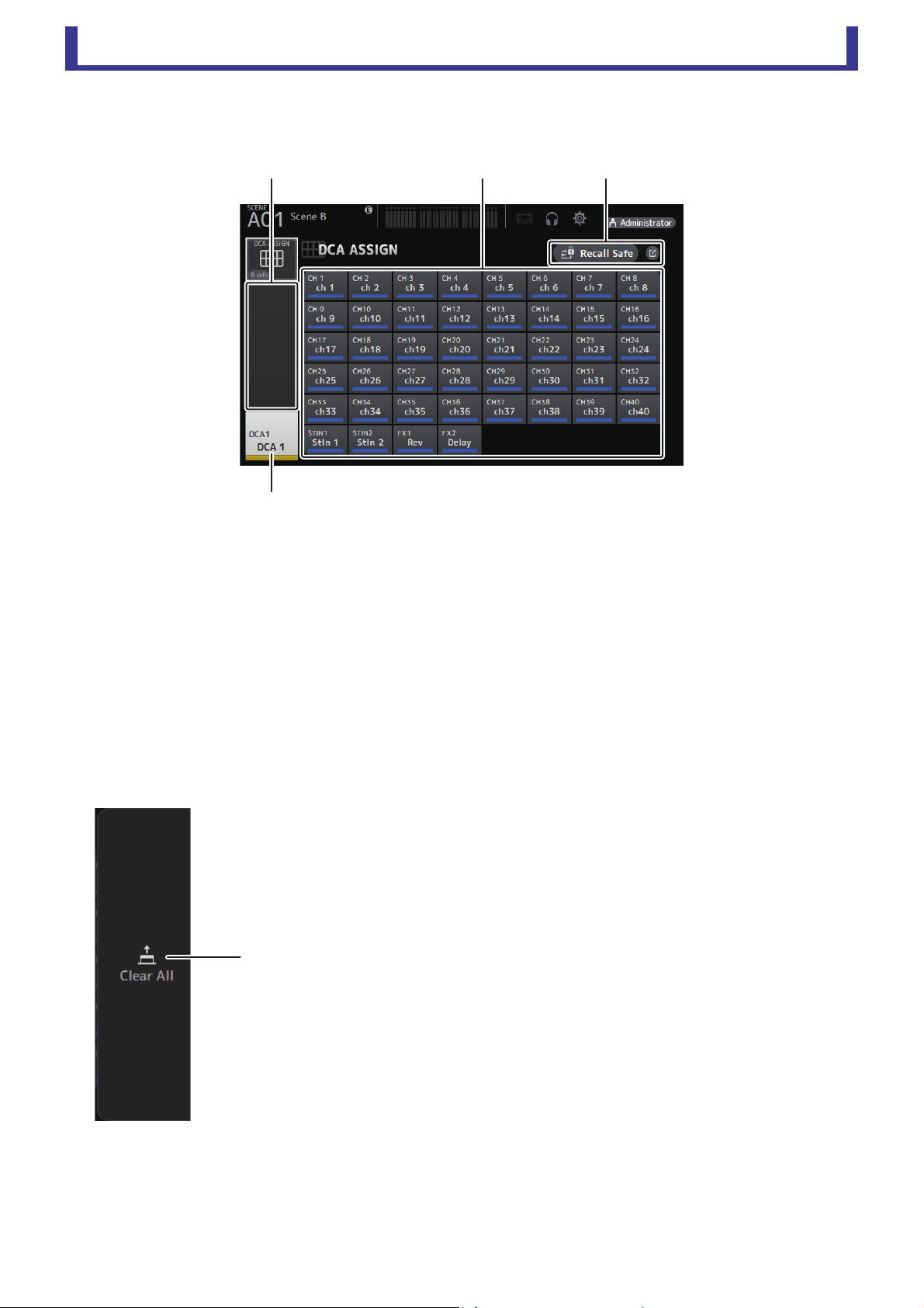
Main display area
User’s Guide
TF Editor
-
83
-
DCA ASSIGN screen
Allows you to group channels together by assigning them to DCA groups.
1 Channel display area
Member channels of selected DCA group assigned to these channel strips
2 DCA ASSIGN buttons
Allow you to select which channels are assigned to the current DCA group.
Selected channels are highlighted.
3 CH VIEW button
Displays the CH VIEW screen (page 66).
4 Recall Safe button
Turns Recall Safe on and off for the corresponding channel.
You can display the RECALL SAFE screen (page 22) by clicking the jump button in the right corner of the Recall Safe button.
DCA ASSIGN screen menu
The following items are displayed in the menu area when the DCA ASSIGN screen is displayed.
1 Clear All
Removes all channels from the DCA group.
ձղմ
ճ
ձ
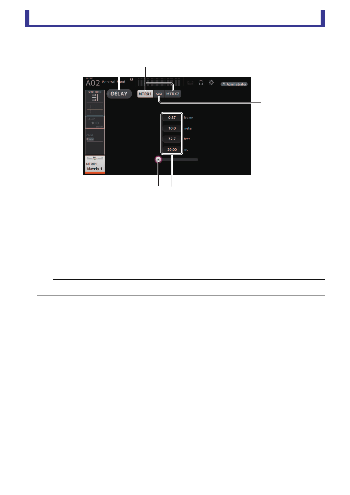
Main display area
User’s Guide
TF Editor
-
84
-
DELAY screen
Sets the delay for signals outputted from the MATRIX channels, and the delay for signals inputted to the ST IN channel.
1 DELAY button
Turns the DELAY on and off.
2 Display selection button
When a MATRIX channel is set to "Stereo", select the MATRIX channel that will display the parameters.
Two buttons are always displayed on the ST IN channel.
3 LR Link button
If the MATRIX channel is set to stereo, the DELAY on/off and delay time operations for the left/right channels will be linked
together when this is turned on. When the delay times are set to a different value, the delay times will operate in linked mode,
maintaining the time difference.
The LR Link button is always displayed on the ST IN channel.
4 DELAY slider
Allows you to adjust the delay time.
You can specify the delay time in frames, meters, feet, or milliseconds.
5 DELAY setting
Determines the delay time by specifying frames, distance (meters or feet) or time (milliseconds). Click a text box to display
the keyboard and enter a value.
NOTE
For MATRIX channels, this is displayed only when the channel is set to stereo. Switch between Stereo and MONOx2 using the BUS SETUP
screen, found on the SETUP screen for this unit. (page 20)
ձ ղ
մ
յ
ճ

Screens of the File Menu
User’s Guide
TF Editor
-
85
-
Screens of the File Menu
Manage Library/Scene screen
This screen allows you to manage Scene data and Library data that is stored in TF Editor.
You can edit Library data and Scene data, and use Library data and Scene data that was saved as a TFF file and handle it as
individual files.
During offline mode, open the screen by selecting Manage Library/Scene from the File menu.
1 Library tab/Scene tab
Allows you to switch between the available screens.
2 Left pane
Displays the folders, .TFP files (Library data), .TFS files (Scene data), and .TFF files stored on the computer. You can use the
checkboxes to select multiple items. When an item is selected, you can click to enter text or edit using the pull-down menu.
You can drag files displayed here and move or copy them to the right pane (TF Editor content) or to a sub-directory.
3 Path display
Displays the path of the list displayed in the left pane. You can also enter a path directly.
Click the sideways left button to move up one level in the directory.
4 / Buttons
Allow you to move to the previous/next directory.
5 Text search box
Allows you to search for items by FileName, Title, and Comment.
6 Right pane
Displays data stored in TF Editor, grouped by bank.
You can use this pane in the same way as the left pane.
You can click the Protect column to turn protection on and off, without selecting the item. When protection is turned on, the
item cannot be edited.
Protected Presets will display with a gray background.
7 Separator
Drag the separator handle to left or right to change the display size of the panes.
NOTE
• When using a touchpanel display, the program may not respond to touchpanel operations as expected if you perform several touchpanel
operations in a short time. In this case, use a mouse or trackpad temporarily, or temporarily move the program to the background.
• If there are too many files displayed in the left pane, it may take more time than expected to sort or select items. This is not a malfunction;
wait for the program to respond. We recommend keeping the number of files displayed in the left pane to less than 1000.
• When displaying a folder in the left pane of the Manage Library/Scene screen, do not perform any operations on that folder directly using
your computer's File Explorer or Finder. If you do, it may take more time than expected to refresh the Manage Library/Scene screen.
䐠䐤䐥䐟 䐟
䐢
䐢
䐡䐣 䐣 䐠 䐤䐥䐡䐣 䐣

Screens of the File Menu
User’s Guide
TF Editor
-
86
-
Toolbar
Displays the same items that are available when you right-click and display the contextual menu.
1 New Folder
Creates a new folder on your computer in the directory specified in the left pane.
2 Extract .tff
Extracts data from a .TFF file and allows you to handle it as an individual file. When you click this item, a dialog is displayed
that allows you to specify where the data will be extracted to. When you extract data, a Library folder and Scene folder are
created in the specified directory and individual files for each bank are extracted.
3 Copy
Copies the selected data.
4 Cut
Cuts the selected data.
5 Paste
Pastes the copied or cut data.
6 Delete
Deletes the selected data.
7 Select All
Selects all data that is displayed.
NOTE
• When using the Manage Library/Scene screen, you cannot drag and drop individual files to your computer's desktop or to a folder on your
computer.
• When copying or moving multiple scene files from the computer, files are moved or copied in order of the location of the destination. If data that
will be overwritten is write-protected, data will not be copied to that location.
• Additionally, if the number of scenes in the bank reaches the limit (100) while copying or moving the scene files, copying or moving stops when
the limit is reached.
• When coping or moving Library data, copying/moving stops if the destination bank contains 1000 items.
ձղճմյ շն
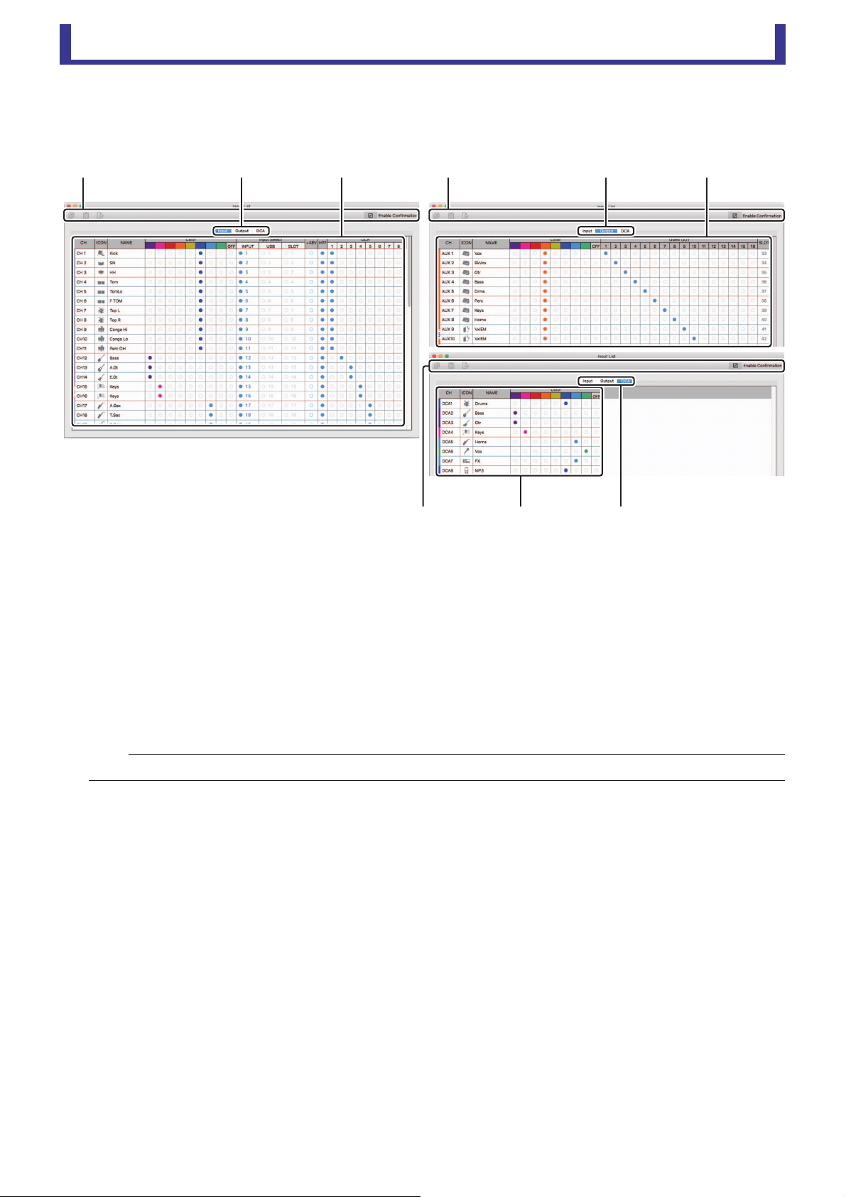
Screens of the File Menu
User’s Guide
TF Editor
-
87
-
Input List screen
Allows you to view and set input channels and output channels, as well as DCA group channel names, channel colors, channel
icons, and patching.
1 Toolbar
Copy button
Copies the selected channel (row), parameter (column), or cell content.
Paste button
Pastes the copied content and applies it to the selected location.
Default button
Resets the selection to its default values.
If this operation is applied to a channel (row), a confirmation message is displayed.
Click OK to reset the channel to its default values. Click Cancel to cancel the reset operation.
When you click a parameter's title, the entire parameter column is selected. If you click the Default button in this state, the
corresponding parameter of the selected channels will be reset to its default values.
Enable Confirmation checkbox
When this checkbox is selected, a confirmation message is displayed when you reset settings to their default values or change
Input Select or OMNI OUT settings.
2 Display view tabs
Allows you to display Input, Output, or DCA information.
3 Edit area
Allows you to set the channel name, channel icon, channel color, and patching for the channel that is displayed. The available
parameters vary depending on the type of channel.
Information changed here will be reflected in the TF Editor main window. Additionally, when the TF series console is
connected, changes are synchronized between the TF Editor and the console.
You can display the context menu by right-clicking (Windows) or control-clicking (Mac) in the Edit area.
NOTE
OMNI OUT settings are not subject to Copy/Paste/Default operations.
䐟䐠䐡
䐟䐠䐡䐟䐠䐡

Screens of the File Menu
User’s Guide
TF Editor
-
88
-
Parameters that can be edited in the Edit area
Stereo Link
Setting and releasing Stereo Link can be performed using the context menu. You can display the context menu by right-
clicking (Windows) or control-clicking (Mac) while a channel is selected.
Linked channels are indicated by an icon of a chain.
Stereo Link is not displayed on the DCA tab.
Channel Icon
Click to display a menu of available channel icons.
Channel Name
Click to enter a name for the channel.
Channel Color
Click a color to assign a color to the channel.
Input Select
Displayed only on the Input tab.
Allows you to set the channel's input source (input port) to INPUT, USB, or SLOT.
When you change this setting, a confirmation message is displayed.
+48V
Displayed only on the Input tab.
Turns phantom power on and off for the input port specified by the Input Select setting.
HPF
Displayed only on the Input tab.
Turns the HPF (high-pass filter) on and off.
DCA
Displayed only on the Input tab.
Allows you to make DCA assignments.
OMNI OUT
Displayed only on the Output tab.
Allows you to patch output channels to OMNI OUT.
When you change the OMNI OUT setting, a confirmation message is displayed.
SLOT
Displayed only on the Output tab.
Displays the port number of the SLOT output for each output channel. (Displayed for reference only.)

Reference
User’s Guide
TF Editor
-
89
-
Reference
Error messages
Message Description
Item Already Exists. Replace it? You tried to overwrite an item in the Library.
File Already Exists, Replace it?
When using Save As, the name of the file you tried to save was the same name as an existing file.
When using Save. you tried to overwrite an existing file.
Operation Failed! An error occurred during the operation. (This is a general error.)
Invalid Name! Name violates naming convention.
Operation Ignored. The feature assigned to the USER DEFINED KNOB could not be operated when the message was displayed.
SCENE #XX is Empty! No data is stored in the Scene you tried to recall, or the data is damaged.
SCENE #XX is Read Only! You tried to overwrite a Scene that is write-protected.
Cannot Store! Could not save the data in the Scene memory or in the library.
Cannot Recall! Could not recall the data from the Scene memory or from the library.
LIBRARY is Read Only! You tried to overwrite data in the library that is write-protected.
Operation Failed. Library Memory Full. You tried to add data when the memory was full.
Turn Off 1-knob Mode to Adjust. 1-knob mode is enabled; turn 1-knob mode off.
Nothing to Paste! You tried to paste data when the copy buffer was empty.
Page does not exist. The page does not exist.
Cannot Close This Popup. The popup could not be closed.
Unsupported File Format! You tried to read an unsupported file format.
Couldn't Write File. The file could not be saved.
File Protected! Could not overwrite the file because the file is write-protected.
Already Exists! The name of the directory you tried to create or edit matches the name of an existing directory.
Couldn't Access File. Could not access the file for some reason.
File Error! An internal file access error occurred.
Illegal IP Address! The IP address setting or gateway setting is incorrect.
Wrong Word Clock! (Slot) Could not sync to the console because the NY64-D sample rate setting is incorrect.
Wrong Word Clock! (Dante Device)
Could not sync to the NY64-D because the sample rate of the device connected to the Dante network that is
connected to the console via the NY64-D is incorrect.
USB Sample Rate Mismatch on USB.
Console:44100Hz
The sample rates of the console and the computer that is connected via the USB TO HOST connector do not
match. (Console: 44.1 kHz, Computer: 48 kHz) Set the computer's sample rate to 44.1 kHz.
USB Sample Rate Mismatch on USB.
Console:48000Hz
The sample rates of the console and the computer that is connected via the USB TO HOST connector do not
match. (Console: 48 kHz, Computer: 44.1 kHz) Set the computer's sample rate to 48 kHz.
Reference
User’s Guide
TF Editor
-
90
-
TF Editor shortcuts
Menu
Shortcuts
Windows Mac
File
Load Ctrl+O Cmd+O
Save Ctrl+S Cmd+S
Exit Alt+F4 Cmd+Q
Home screen ESC ESC
SEL CH
Left Ctrl+ Cmd+
Right Ctrl+ Cmd+
FADER BANK
INPUT Ctrl+1 Cmd+1
GROUP Ctrl+2 Cmd+2
OUTPUT Ctrl+3 Cmd+3
CUSTOM Ctrl+4 Cmd+4
SCENE screen Ctrl+5 Cmd+5
Meter screen Ctrl+6 Cmd+6
Library screen Ctrl+L Cmd+L
Menu
Copy Ctrl+Shift+C Cmd+Shift+C
Paste Ctrl+Shift+V Cmd+Shift+V
Cut Ctrl+Shift+X Cmd+Shift+X
CH NAME screen F2 F2
TOUCH AND TURN
Inc/Dec Mouse wheel / Mouse wheel /
Inc/Dec (Fine)
Shift+Mouse wheel /
Shift+/
Shift+Mouse wheel /
Shift+/
Window Zoom
100% Ctrl+Alt+1 Cmd+Option+1
150% Ctrl+Alt+2 Cmd+Option+2
200% Ctrl+Alt+3 Cmd+Option+3
Manage Library/Scene Screen
Search Ctrl+F Cmd+F
Copy Ctrl+C Cmd+C
Cut Ctrl+X Cmd+X
Paste Ctrl+V Cmd+V
Select All Ctrl+A Cmd+A
Drag to move Shift+drag Cmd+drag
Drag to copy Ctrl+drag Option+drag
Move up one level in
hierarchy
Backspace Cmd+
Move down one level in
hierarchy
Enter Cmd+
Extract from TFF file Double-click Cmd+O, double-click
Delete Delete Cmd+Delete
Display contextual menu Shift+F10, right-click Ctrl+click

Index
User’s Guide
TF Editor
-
91
-
Index
Numerics
1-knob COMP........................ 54
1-knob EQ ............................. 48
Intensity ............................. 48
Loudness ........................... 48
Vocal.................................. 48
A
ASSIGN screen ..................... 63
AUTOMIXER screen ............. 64
AUX 9/10–19/20 channels..... 35
AUX1–AUX8 channels .......... 35
B
BUS SETUP screen .............. 20
C
CH NAME screen .................. 78
CH VIEW screen ................... 66
Channel strip area ................. 11
COMP screen........................ 53
COMP screen menu.............. 54
CONNECT area ...................... 9
CONNECT screen................... 5
CUE....................................... 17
CUSTOM FADER BANK
screen .................................. 28
CUSTOM FADER BANK
screen menu ........................ 28
D
DCA ASSIGN screen ............ 83
DCA groups........................... 83
DELAY screen....................... 84
Digital gain............................. 46
Direct out ............................... 67
E
EFFECT TYPE screen .......... 56
EQ screen ............................. 48
EQ screen menu ................... 50
Error messages ..................... 89
F
FADER BANK area ................. 9
Footswitch ............................. 26
FX screen
(FX1/2, InsFX1–6)................ 55
FX screen menu .................... 56
G
GainFinder............................. 46
GATE screen......................... 51
GATE screen menu............... 52
GEQ screen........................... 79
I
Input List screen .................... 87
INPUT screen........................ 45
INPUT screen menu.............. 47
L
Level meter............................ 16
Library ................................... 30
LIBRARY screen ................... 30
LOG screen ........................... 29
M
Manage Library/Scene
screen .................................. 85
Master/FX/ST IN strip area.... 11
MATRIX1–MATRIX4
channels............................... 36
Menu area ............................. 10
Menu bar
File menu............................. 6
Help menu ........................... 7
Setup menu ......................... 7
Window menu...................... 7
METER screen ...................... 16
Metering point........................ 16
Monitor .................................. 17
MONITOR screen.................. 17
MUTE area .............................. 9
N
Navigation area ..................... 37
O
Offline editing .......................... 6
OMNI OUT ............................ 21
OMNI OUT screen................. 21
OMNI OUT screen menu....... 21
Oscillator ............................... 18
OUTPUT screen.................... 81
OVERVIEW screen ............... 33
OVERVIEW screen
operations ............................ 33
P
Peak Hold.............................. 16
Phantom power ............... 19, 46
Phase .................................... 45
Preset .................................... 30
R
Recall on/off checkboxes ...... 30
Recall safe............................. 22
RECALL SAFE screen .......... 22
S
Scene .................................... 13
SCENE screen ...................... 13
SCENE screen menu ............ 15
SELECT MIXER TYPE
screen .................................... 4
SEND FROM screen ............. 82
Send pan ............................... 82
SEND TO AUX screen .......... 62
SETUP screen....................... 19
SOFT KEYBOARD screen .... 32
Stereo link ............................. 45
Syncing.................................... 5
T
Toolbar .................................. 12
U
USER DEFINED CONTROLS
screen .................................. 24
USER DEFINED KEYS ......... 24
USER DEFINED KNOBS ...... 25
I Operations and
settings
C
Computer keyboard................. 4
Copying and pasting channel
settings................................. 37
CUSTOM FADER BANK
Recalling.............................. 9
Setting ............................... 28
D
DCA groups
Assigning channels............ 83
E
EQ
1-knob EQ mode ............... 48
HPF ................................... 48
LPF .................................... 50
Manual mode..................... 48
F
Feature assignments
Assigning to footswitch ...... 26
Assigning to [USER
DEFINED KEYS] ............... 24
Assigning to [USER
DEFINED KNOBS] ............ 25
I
Insert effects
Setting ............................... 56
M
Mouse wheel ........................... 4
P
Presets
Editing................................ 30
Recalling............................ 30
R
Recall safe
Using recall safe ................ 22
S
Scene
Editing................................ 13
Recalling............................ 13
Setting
Compressor ....................... 53
Effects................................ 55
Insert effects ...................... 56
Oscillator............................ 18
SEND FROM level............. 62
Stereo link, input source .... 45
T
Touch screen........................... 4
U
Using GEQ ............................ 79

Published 03/2019 CR-H0
© 2015 Yamaha Corporation
Manual Development Group
Yamaha Downloads
https://download.yamaha.com/
Yamaha Pro Audio global website
http://www.yamahaproaudio.com/