Loading ...
Loading ...
Loading ...
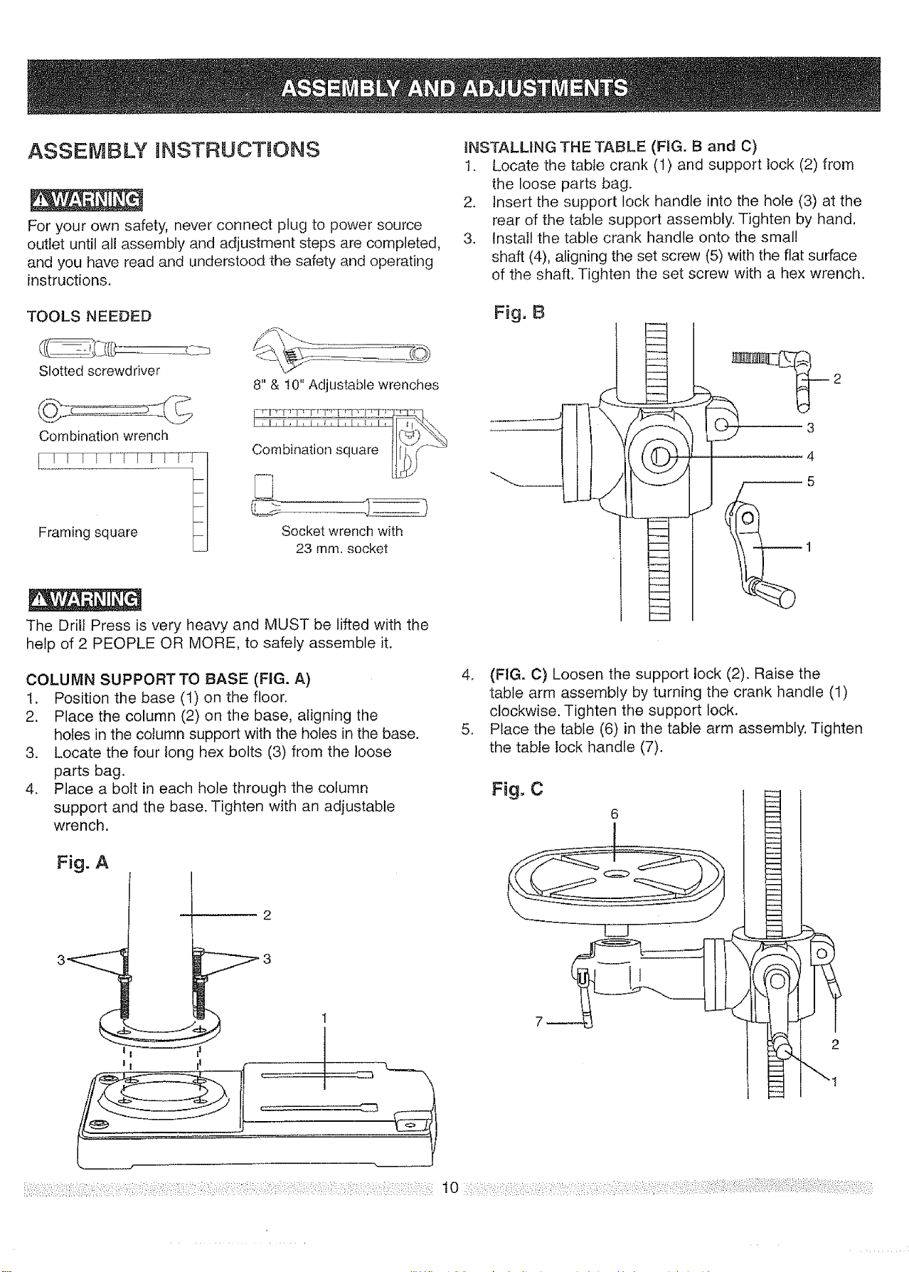
ASSEMBLY NSTRUCTJONS
For your own safety, never connect plug topower source
outlet until all assembly and adjustment steps are completed,
and you have read and understood the safety and operating
instructions.
iNSTALLING THE TABLE (F_G. B and C)
1. Locate the table crank (1) and support tock (2) from
the loose parts bag.
2. Insert the support lock handle into the hole (3) at the
rear of the table support assembly. Tighten by hand,
3. Install the table crank handle onto the small
shaft (4), aligning the set screw (5) with the flat surface
of the shaft. Tighten the set screw with a hex wrench.
TOOLS NEEDED
Slotted screwdriver
Combination wrench
[ ! L L! ! r_-!_
Framing Square fl
8"& t0" Adjustable wrenches
Combination square _--_"
Socket wrench with
23 mm. socket
The Drill Press is very heavy and MUST be lifted with the
help of 2 PEOPLE OR MORE, to safely assemble it.
Fig, B
2
COLUMN SUPPORTTO BASE (FIG. A)
1. Position the base (1) on the floor.
2. Place the column (2) on the base, aligning the
holes in the column support with the holes in the base.
3. Locate the four long hex bolts (3) from the ]oose
parts bag.
4. Place aboft in each hole through the column
support and the base. Tighten with an adjustable
wrench.
Fig, A
4. (FIG. C) Loosen the support lock (2). Raise the
table arm assembly by turning the crank handle (1)
clockwise. Tighten the support lock.
5. Place the table (6) in the table arm assembly, Tighten
the table lock handle (7).
Fig, C
I
INSTALLING THE HEAD (FIG. D)
The Drill Press head is very heavy and MUST be lifted with
the help of 2 PEOPLE OR MORE, to safely assemble the
Drill Press head on the column.
1. Carefully lift the head (t) above the column (2) and
slide it onto the column. Make sure the head slides
down over the column as far as possible. Align the
head with the base.
2. Using [he hex wrench, tighten the two head lock set
screws (3) on the right side of the head.
Fig. D
3
2
FENCE ASSEMBLY (F_G.E)
This drill press has a channeled tabfe top.
1. Determine the desired location for the fence (1). Slide
the T-blocks (2) into the appropriate channels as
shown.
2. Align the mounting holes of the fence over the T-block's
threaded holes.
3. Place a washer (3) on the threaded end of the knob (4).
Insert the knob through the mounting hole of the fence
into the T-block, and tighten,
4. Repeat for the other knob and T-block.
Fig. E 4
INSTALLING THE CHUCK {FIG. F, G, and H)
1. Clean out the tapered hole in the chuck (1) with a
clean cloth.
2. Clean tapered surfaces on the arbor (2) and spindle (3).
CAUTION: Make sure there are no foreign particles
sticking to the surfaces. The slightest piece of dirt on
any of these surfaces will prevent the chuck from
seating properly. This will cause the drill chuck and
bit to wobble. If tapered hole inside spindle is
extremely dirty, use a cleaning solvent.
Fig. F
3
--ta 0
3. (FIG. G) Push the chuck (1) onto the spindle
arbor (2), Tap gently to ensure seat.
4. Lower the spindle by turning the feed handles (3)
counterclockwise, until the slot (4) appears on the
quill (5).
5. Push the chuck and spindle arbor up into the spindle,
making sure the tang (upper narrow end of the
spindle arbor shank) is engaged and locked in the
inner slot (6) of the spindle. This can be seen
through the outer slot (4) of the quill by rotating the
chuck and arbor until the two slots are aligned.
6. Open the jaws of the chuck (1) by rotating the chuck
sleeve clockwise. To prevent damage, make sure the
jaws are completely receded into the chuck.
Fig. G
Loading ...
Loading ...
Loading ...