
229365-15
GAS BRATT PAN
G580-8 G580-8E
G580-12 G580-12E
I N S T A L L A T I O N A N D O P E R A T I O N M A N U A L

The reproduction or copying of any part of this manual by any means whatsoever is strictly forbidden unless authorized previously in
writing by the manufacturer.
In line with policy to continually develop and improve its products, Moffat Ltd. reserves the right to change the specifications and
design without prior notice.
© Copyright Moffat Ltd. October 2018.
Moffat Limited
Rolleston 7675
New Zealand
AUSTRALIA
Moffat Pty Limited
Web: www.moffat.com.au
E.Mail: [email protected]m.au
Main Office: (tel) +61 (03) 9518 3888
(fax) +61 (03) 9518 3838
Service: (tel): 1800 622 216
Spares: (tel): 1800 337 963
Customer Service: (tel): 1800 335 315
(fax): 1800 350 281
CANADA
Serve Canada
Web: www.servecanada.com
E.Mail: [email protected]m
Sales: (tel): 800 551 8795 (Toll Free)
Service: (tel): 800 263 1455 (Toll Free)
NEW ZEALAND
Moffat Limited
Web: www.moffat.co.nz
E.Mail: [email protected].nz
Main Office: (tel): 0800 663328
UNITED KINGDOM
Blue Seal
Web: www.blue-seal.co.uk
E.Mail: sales@blue-seal.co.uk
Sales: (tel): +44 121 327 5575
(fax): +44 121 327 9711
Spares: (tel): +44 121 322 6640
(fax): +44 121 327 9201
Service: (tel): +44 121 322 6644
(fax): +44 121 327 6257
UNITED STATES
Moffat
Web: www.moffat.com
Sales: (tel): 1-800 551 8795 (Toll Free)
(tel): 336 661 1556
(fax): 336 661 9546
Service: (tel): 866 673 7937 (Toll Free)
REST OF WORLD
Moffat Limited
Web: www.moffat.co.nz
E.Mail: export@moffat.co.nz
G580-8 BRATT PAN MANUAL TILT (80 ltr)
G580-8E BRATT PAN ELECTRIC TILT (80 ltr)
G580-12 BRATT PAN MANUAL TILT (120 ltr)
G580-12E BRATT PAN ELECTRIC TILT (120 ltr)
Model Numbers Covered in this Specification
General
Gas Supply Requirements
Electrical Supply Requirements
Water Supply Requirements
Installation Requirements
Unpacking
Location
Assembly
Gas Connection
Electrical Connection
Water Connection
Commissioning
Operation Guide
Description of Controls
Lighting Pilot Burner
Lighting Main Burner
Setting the Temperature
Operating the Water Supply Valve
Tilting the Pan - G580-8 / G580-12
Tilting the Pan - G580-8E / G580-12E
Turning off the Bratt Pan (All Models)
General
After Each Use
Daily Cleaning
Weekly Cleaning
Periodic Maintenance
Conversion Procedure
Gas Specifications
2
We are confident that you will be delighted with your WALDORF GAS BRATT PAN, and it will become a
most valued appliance in your commercial kitchen.
To ensure you receive the utmost benefit from your new Waldorf GAS BRATT PAN, there are two important
things you can do.
Please read the instruction book carefully and follow directions given. The time taken will be well spent.
If you are unsure of any aspect of the installation, instructions or performance of your appliance,
contact your WALDORF dealer promptly. In many cases a phone call could answer your question.
These instructions are only valid if the country code appears on the appliance. If the code does not
appear on the appliance, refer to the supplier of this appliance to obtain the technical instructions for
adapting the appliance to the conditions for use in that country.
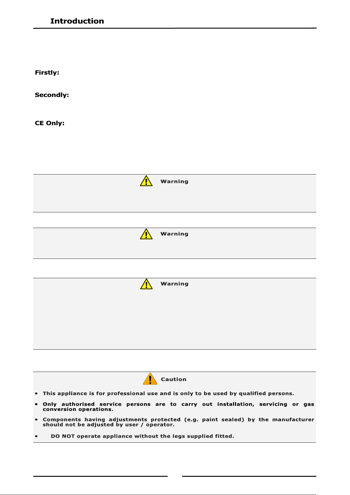
GREAT CARE MUST BE TAKEN BY THE OPERATOR TO USE THE EQUIPMENT SAFELY TO GUARD IT AGAINST RISK OF
FIRE.
APPLIANCE MUST NOT BE LEFT ON UNATTENDED.
IT IS RECOMMENDED THAT A REGULAR INSPECTION IS MADE BY A COMPETENT SERVICE PERSON TO
ENSURE CORRECT AND SAFE OPERATION OF YOUR APPLIANCE IS MAINTAINED.
DO NOT STORE OR USE GASOLINE OR OTHER FLAMMABLE VAPOURS OR LIQUIDS IN THE VICINITY OF
THIS OR ANY OTHER APPLIANCE.
DO NOT SPRAY AEROSOLS IN THE VICINITY OF THIS APPLIANCE WHILE IT IS IN OPERATION.
IMPROPER INSTALLATION, ADJUSTMENT, ALTERATION, SERVICE OR MAINTENANCE CAN CAUSE PROPERTY
DAMAGE, INJURY OR DEATH. READ THE INSTALLATION, OPERATING AND MAINTENANCE INSTRUCTIONS
THOROUGHLY BEFORE INSTALLING OR SERVICING THIS APPLIANCE.
INSTRUCTIONS TO BE FOLLOWED IN THE EVENT THE USER SMELLS GAS ARE TO BE POSTED IN A PROMINENT
LOCATION. THIS INFORMATION SHALL BE OBTAINED BY CONSULTING THE LOCAL GAS SUPPLIER.

3
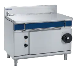
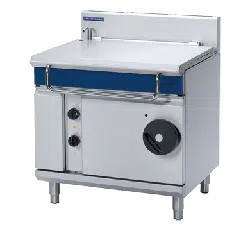
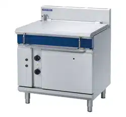
G580-8 / G580-8E - Gas Bratt Pan, Manual / Electric Tilt - 900mm wide (80ltr).
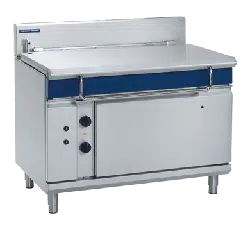
G580-12 / G580-12E - Gas Bratt Pan, Manual / Electric Tilt - 1200mm wide (120ltr).
G580-8 /G580-8E (80 ltr) Gas Bratt Pan.
A commercial heavy duty, gas fired Bratt Pan fitted with an 80 ltr capacity pan, of full stainless steel pan
construction, with a single 6 bar chrome plated steel gas burner and electric piezo ignition giving even
heat distribution. This appliance features an electric thermostat burner control and over temperature
safety cut-out.
Created for compact modular kitchens, it is fitted with manually (or optional electric power) operated
tilting mechanism with a burner cut-out when the pan is tilted.
G580-12 /G580-12E (120 ltr) Gas Bratt Pan.
A commercial heavy duty, gas fired Bratt Pan fitted with an 120 ltr capacity pan, of full stainless steel
pan construction, with a single 8 bar chrome plated steel gas burner and electric piezo ignition giving
even heat distribution. This appliance features an electric thermostat burner control and an over-
temperature safety cut-out.
Created for compact modular kitchens, it is fitted with manually (or optional electric power) operated
tilting mechanism fitted with a burner cut-out when the pan is tilted.
4
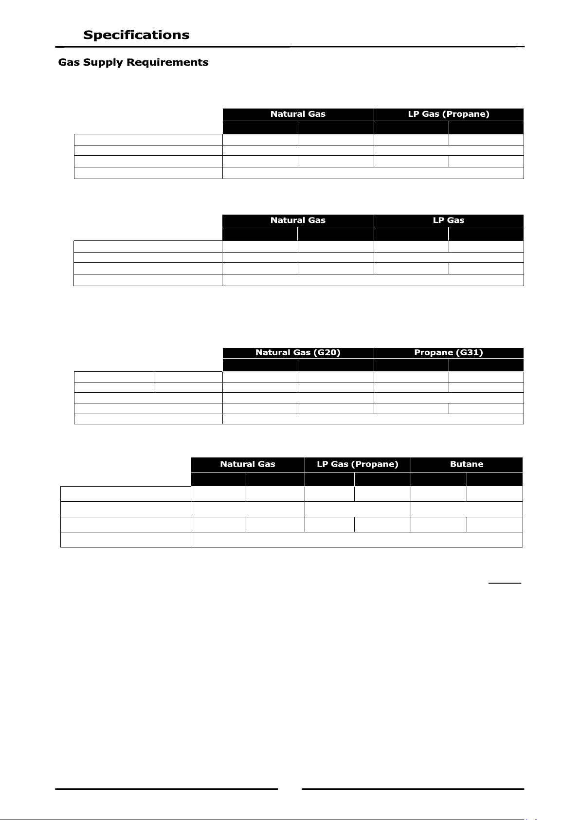
- Australia:
- New Zealand:
- UK Only:
Category: II
2H3P.
Flue Type: A
1.
- All Other Markets:
NOTE:
* - Measure burner operating pressure at the gas control outlet test point with burner
operating at ‘High’ setting. Operating pressure is ex-factory set through appliance
regulator and is not to be adjusted, apart from when carrying out gas conversion, if
required. (Refer to ‘Gas Conversion’ section for details).
G580-8 / 8E G580-12 / 12E G580-8 / 8E G580-12 / 12E
Input Rating (N.H.G.C.) 72MJ/hr 90MJ/hr 72MJ/hr 90MJ/hr
Supply Pressure 1.13 - 3.40kPa 2.75 - 4.50kPa
Burner Operating Pressure (*) 0.76kPa 0.60kPa 2.5kPa 2.4kPa
Gas Connection ¾” BSP Male
G580-8 / 8E G580-12 / 12E G580-8 / 8E G580-12 / 12E
Heat Input (nett)
Nominal
18.5kW 23kW 18.5kW 23kW
Gas Rate (nett)
Nominal
1.96m
3
/hr 2.43m
3
/hr 1.44kg/hr 1.79kg/hr
Supply Pressure 20mbar 37mbar
Burner Operating Pressure (*) 7.5mbar 6.0mbar 25.7mbar 25.5mbar
Gas Connection
3
/
4
” BSP Male
G580-8 / 8E G580-12 / 12E G580-8 / 8E G580-12 / 12E
Input Rating (N.H.G.C.) 72MJ/hr 90MJ/hr 72MJ/hr 90MJ/hr
Supply Pressure 1.13 - 3.40kPa 2.75 - 4.50kPa
Burner Operating Pressure (*) 0.76kPa 0.60kPa 2.5kPa 2.4kPa
Gas Connection ¾” BSP Male
G580-8 / 8E G580-12 / 12E G580-8 / 8E G580-12 / 12E BP8080G / GE BP8120G / GE
Input Rating (N.H.G.C.) 72 MJ/hr 90 MJ/hr 72 MJ/hr 90 MJ/hr 72 MJ/hr 90 MJ/hr
Supply Pressure 1.13 - 3.40 kPa 2.75 - 4.50 kPa 2.75 - 4.50 kPa
Burner Operating Pressure (*) 0.76 kPa 0.60 kPa 2.5kPa 2.4kPa 2.5kPa 2.4kPa
Gas Connection ¾” BSP Male
5
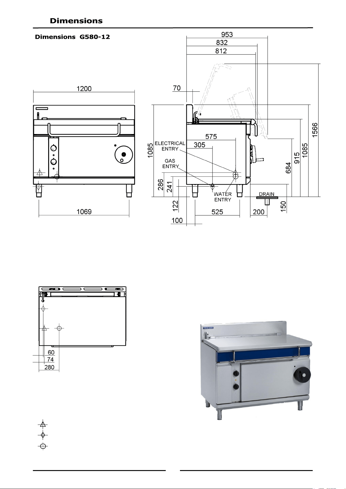
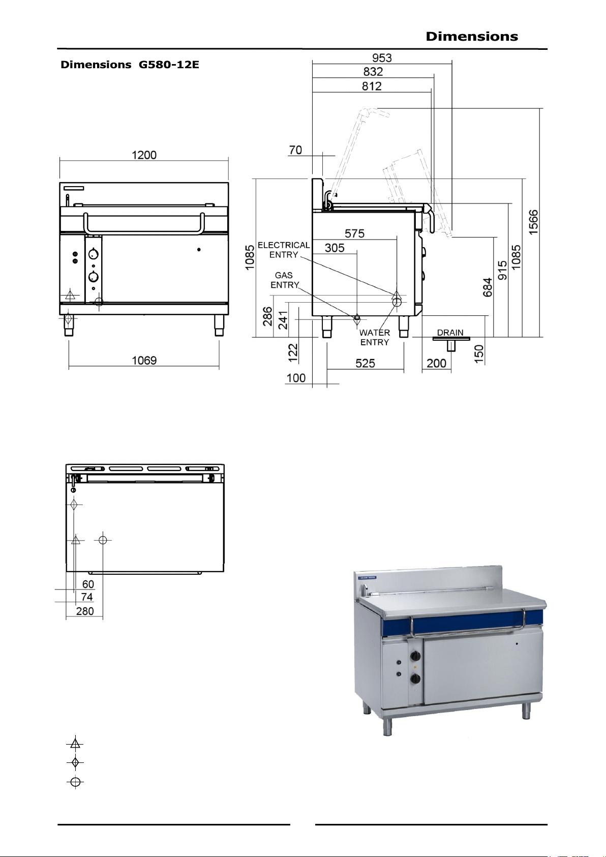
Gas supply connection point is located at rear of appliance, approximately 60mm from left hand side,
305mm from rear, 122mm from floor and is reached from beneath appliance. (Refer to ‘Dimensions’
section).
Connection is ¾" BSP male thread.
G580-8 / G580-12 - 220-240V a.c, 50 / 60Hz, 0.1kW, 1P+N+E.
G580-8E / G580-12E - 220-240V a.c, 50 / 60Hz, 0.35kW, 1P+N+E.
Cold water connection is
1
/
2
" tube connection via 15mm crox fitting located 280mm from LH side, 575mm
from rear and 241mm from floor.
Water supply must be protected by an in line sediment filter / strainer, which should be fitted into pipeline
prior to Bratt Pan water connection.
Maximum water supply pressure 550 kPa (80 psi).
Maximum inlet water temperature - 80°C.
6
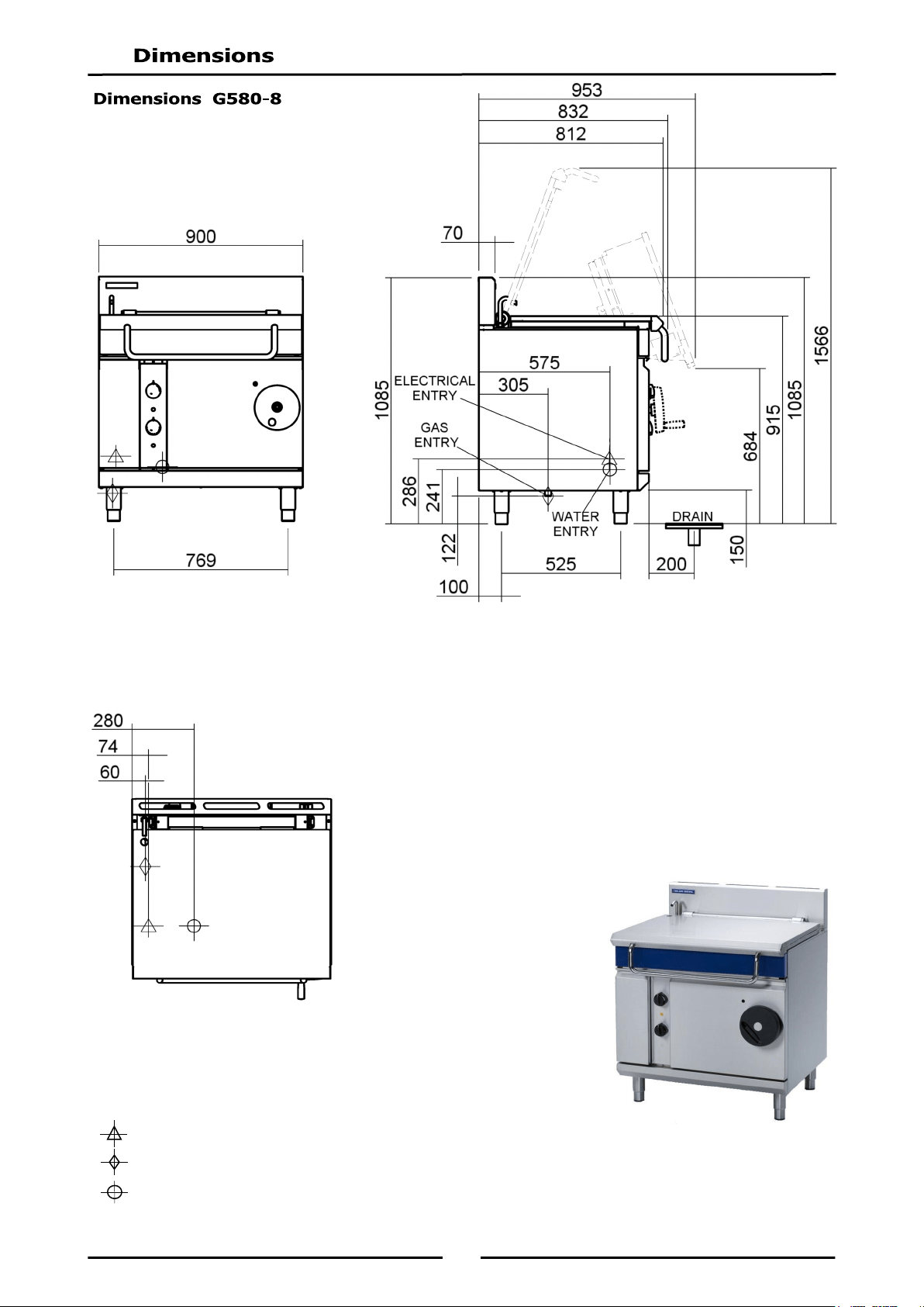
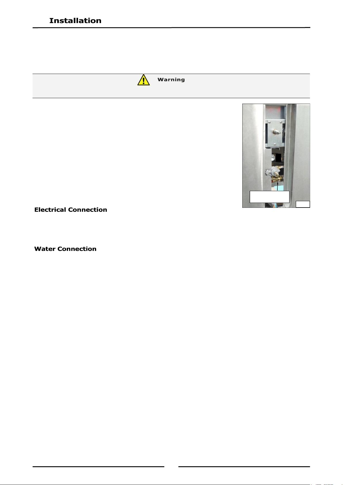
Electrical Connection Point.
Gas Connection Point.
Water Connection Point.
575
FRONT
G580-8
SIDE
G580-8
PLAN
G580-8
7
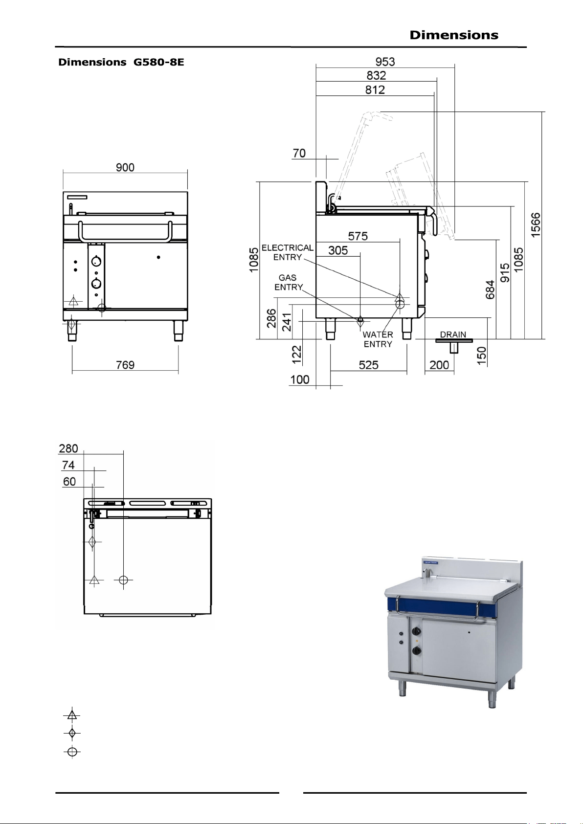
Electrical Connection Point.
Gas Connection Point.
Water Connection Point.
FRONT
G580-8E
SIDE
G580-8E
PLAN
G580-8E
8
Electrical Connection Point.
Gas Connection Point.
Water Connection Point.
FRONT
G580-12
SIDE
G580-12
PLAN
G580-12
9
Electrical Connection Point.
Gas Connection Point.
Water Connection Point.
FRONT
G580-12E
SIDE
G580-12E
PLAN
G580-12E
10
NOTE: It is most important that this appliance is installed correctly and that operation is
correct before use. Installation shall comply with local gas, electrical and health and
safety requirements.
Blue Seal Bratt Pans are designed to provide years of satisfactory service, and correct installation is
essential to achieve the best performance, efficiency and trouble-free operation.
This appliance must be installed in accordance with National installation codes and in addition, in
accordance with relevant National / Local codes covering gas, electrical, fire and health and safety.
Australia: - AS5601 - Gas Installations.
New Zealand: - NZS5261 - Gas Installation.
Australia / New Zealand: - AS/NZS3000 - Wiring Rules.
- AS / NZS 3500 - Plumbing and Drainage.
United Kingdom: - Gas Safety (Installation & Use) Regulations 1998.
- BS6173 - Installation of Catering Appliances.
- BS5440 1 & 2 - Installation Flueing & Ventilation.
- BS7671 - Requirements for Electrical Installation.
Ireland: - IS 820 - Non-Domestic Gas Installations.
Installations must be carried out by authorised persons only. Failure to install equipment to
the relevant codes and manufacturer’s specifications shown in this section will void the
warranty.
Components having adjustments protected (e.g. paint sealed) by the manufacturer are only
to be adjusted by an authorised service agent. They are not to be adjusted by the installation
person.
Remove all packaging.
Check equipment and parts for damage. Report any damage immediately to the carrier and
distributor.
Ensure the 4 adjustable feet with the protruding centre screw are fitted.
Remove protective plastic coating from side panels.
Report any deficiencies to distributor who supplied bratt pan.
Check available gas supply is correct to as shown on rating plate located on bottom corner of front
right hand panel.
1. Installation must allow for sufficient flow of fresh air for combustion air supply.
2. Any gas burning appliance requires adequate clearance and ventilation for optimum and trouble-free
operation.
Combustion Air Requirements
3. Never directly connect a ventilation system to appliance flue outlet.
4. Installation must include adequate ventilation means, to prevent dangerous build up of combustion
products.
5. Position Bratt Pan in its approximate working position.
6. All air for burner combustion is supplied from beneath the unit. Legs must always be fitted and no
obstructions placed beneath or around base of appliance, as obstructions will cause incorrect
operation and / or failure of appliance.
NOTE: Do not obstruct or block appliances flue. Never directly connect a ventilation system
to appliance flue outlet.
Natural Gas 19m
3
/hr 24m
3
/hr
LPG / Propane 20m
3
/hr 24m
3
/hr
11
The following minimum installation clearances are to be adhered to:
NOTE: Only non-combustible materials can be used in close proximity to this appliance.
NOTE:
This appliance must only be installed on adjustable feet supplied. It must not be
fitted with rollers or castors as this appliance is intended for stationary installations
only.
Appliance must be positioned securely and level. This should be carried out on
completion of gas connection. Refer to ‘Gas Connection’ section.
Optional Accessories (Refer to Replacement Parts List)
Plinth Kit. For installation details, refer to instructions supplied with each kit.
1. Check that all feet are in place and are tightened firmly.
2. Roughly adjust feet to make bratt pan steady and level.
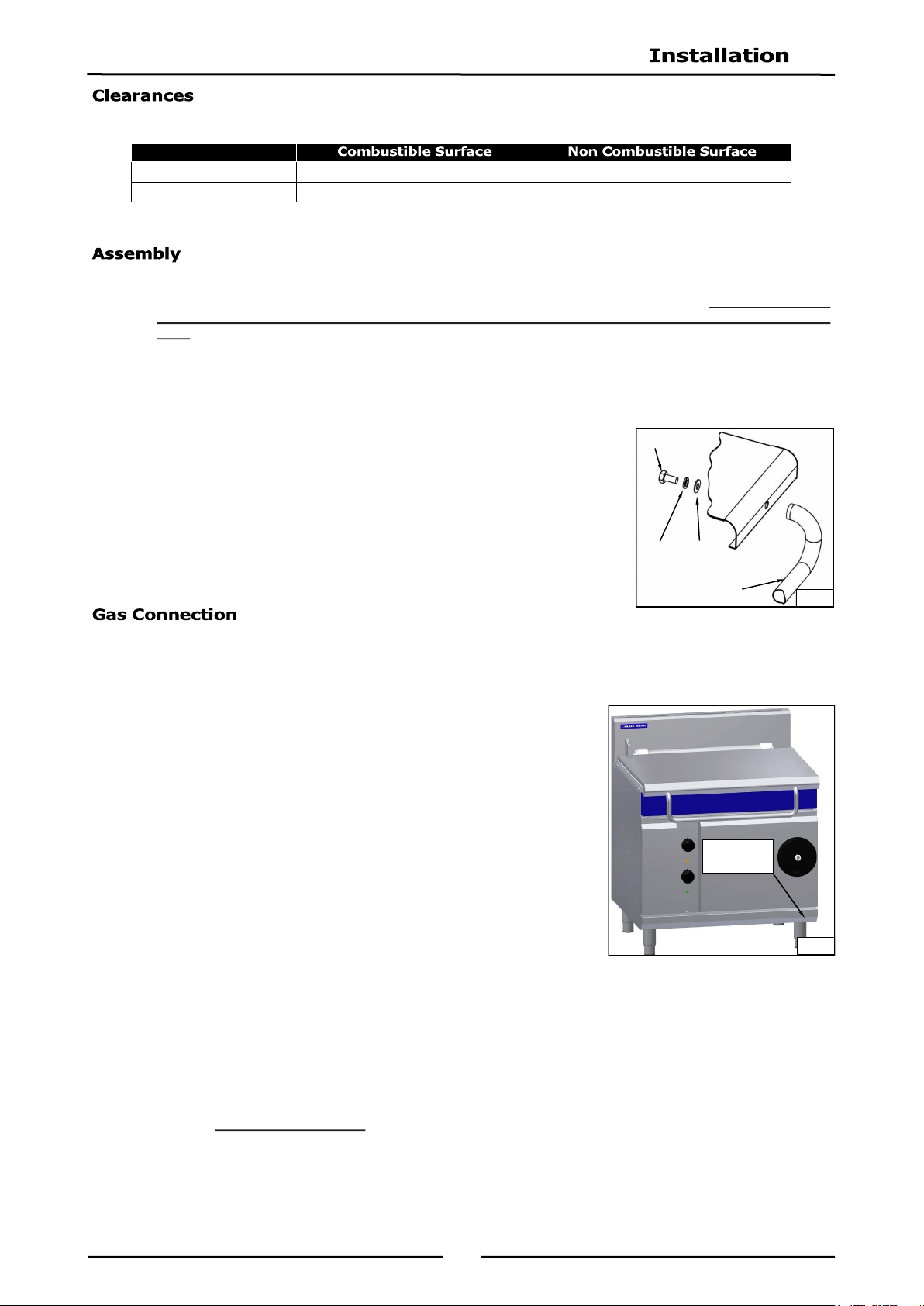
3. To assemble handle to lid, unpack handle assembly. Place handle on
outside of lid with curved part of handle facing downwards. (Refer to
Fig 1).
4. Fit bolts with spring washers and flat washers from inside of lid and
tighten bolts to secure handle in position.
NOTE: ALL GAS FITTING MUST ONLY BE CARRIED OUT BY AN AUTHORISED PERSON.
1. It is essential that gas supply is correct for appliance to be installed and that adequate supply
pressure and volume are available. The following checks should be made before installation:-
a. Gas Type the appliance has been supplied for is show n
on coloured stickers located above gas connection and on
rating plate. Check that this is correct for gas supply appliance
is being installed for. Gas conversion procedure is detailed in
this manual.
b. Supply Pressure required for this appliance is show n in
‘Specifications’ section of this manual. Check gas supply to
ensure adequate supply pressure exists.
c. Input Rate of this appliance is show n on Rating Plate
and in 'Specifications' Section of this manual. Input rate
should be checked against available gas supply line capacity.
Particular note should be taken if appliance is being
added to an existing installation.
NOTE: It is important that adequately sized piping runs directly to connection joint on
appliance with as few tees and elbows as possible to give maximum supply volume.
2. Fit gas regulator supplied, into gas supply line as close to appliance as possible.
NOTE: Gas pressure regulator provided with this appliance is convertible between Natural Gas
and LPG as shown in ‘Gas Conversion Section’ in this manual.
Ensure regulator is converted to correct gas type that appliance will operate on.
Regulator outlet pressure is fixed ex-factory for gas type that regulator is converted to
and it is NOT to be adjusted.
Regulator connections are
3
/
4
" BSP female.
Connection to appliance is
3
/
4
" BSP male.
(Refer to 'Specifications' section for gas supply location dimensions).
NOTE: A Manual Isolation Valve must be fitted to individual appliance supply line.
Handle
Nut
Spring & Flat
Washers
Fig 1
Lid
Rating Plate
Location
Fig 2
Left / Right hand side 50mm 0mm
Rear 50mm 0mm
12
3. Correctly locate appliance into its final operating position and using a spirit level, adjust legs so that
unit is level and at correct height.
4. Connect gas supply to appliance. A suitable joining compound which resists breakdown action of
LPG must be used on every gas line connection, unless compression fittings are used.
5. Check all gas connections for leakages using soapy water or other gas detecting equipment.
6. Check gas operating pressure is as shown in 'Specifications' section.
NOTE: Operating pressure is to be measured at gas control outlet
test point with burner operating at ‘High Flame’ setting.
7. Verify operating pressure remains correct.
1. Electrical systems are all connected through a 2m, 10 amp flex located at LH side of unit.
2. For immediate electric supply, plug lead into a properly earthed, 220-240V, 50 Hz, 1P+N+E, 3 pin
socket.
NOTE:
Water supply must be protected by an in line sediment filter / strainer, which should
be fitted into pipeline prior to Bratt Pan water connection.
All water pipework must be thoroughly flushed prior to completion of installation
procedure.
Cold water mains ¾” BSP male thread connection point. For location details on services connections refer
to drawings in ‘Specification’ section.
Maximum water supply pressure - 550 kPa (80 psi).
Maximum water supply temperature - 80°C.
Remove control panel for access to cold water connection.
Fig 3
Gas Control Outlet
Test Point
DO NOT USE A NAKED FLAME TO CHECK FOR GAS LEAKAGES.

13
Before leaving the new installation;
Check the following functions in accordance with operating instructions shown in ‘Operation’ section
of this manual.
Ensure all water pipework has been thoroughly flushed through prior to using bratt pan.
Light Pilot Burners.
Light Main Burners.
Check main burner operation ‘ON’ / ‘OFF’ with Thermostat Control.
Ensure operator has been instructed in areas of correct lighting, operation, and shutdown procedure
for appliance.
This manual must be kept by owner for future reference, and a record of
Date of Purchase,
Date of
Installation
and
Serial Number of Unit
recorded and kept w ith this manual. (These details can
be found on Rating Plate attached to bottom corner of front right hand panel. Refer to ‘Gas
Connection’ section).
NOTE: If for some reason it is not possible to get appliance to operate correctly, shut ‘Off’ gas
supply and contact supplier of this appliance.
14
1. Blue Seal bratt pans have been designed to provide simplicity of operation and 100% safety
protection.
2. Improper operation is almost impossible, however bad operation practices can reduce life of bratt
pan and produce a poor quality product. To use this bratt pan correctly please carefully read the
following sections.
Description of Controls.
Lighting Pilot Burner.
Lighting Main Burner.
Setting Temperature.
Operating Water Supply Valve.
Tilting the Pan - G580-8 / G580-12 Models Only.
Tilting the Pan - G580-8E / G580-12E Model Only.
Turning Off the Bratt Pan.
15
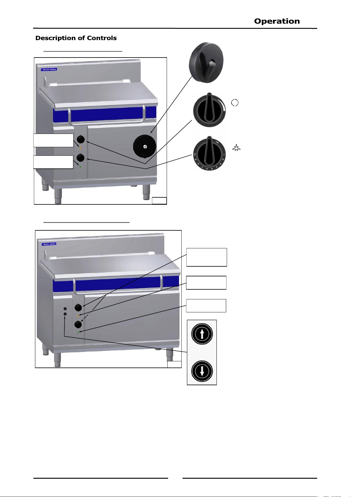
G580-8 / G580-12 Models.
G580-8E / G580-12E Models.
Manual Tilt Handwheel
(8 &12 Models only)
Water Flow Control Valve
(All Models)
OFF Position
Graduated Flow
Gas Control Knobs
(All Models)
Pilot Burner
Graduations from 1 to 10
for heat control.
Electrical Tilt Controls
(8E & 12E Models only)
With bratt pan lid open, bratt
pan can be electrically raised to
‘UP’ position.
Fig 4
Power Indicator
Lamp (White)
Heating Indicator
Lamp (Amber)
Controls are as
for Models
shown above
Fig 5
Power Indicator
Lamp (White)
Heating Indicator
Lamp (Amber)
16
1. Ensure mains power and gas supply is turned ‘On’ at mains supply.
2. Push-in gas control knob and rotate anti-clockwise to PILOT position. Power indicator light (Green)
should illuminate and ignitor should be heard operating.
3. Hold gas control knob depressed, igniter will continue to operate until pilot is alight.
4. Once pilot is lit (view through viewing port at front of bratt pan), continue holding ‘IN’ gas control
knob for approximately 10 seconds, then release. The pilot burner should remain alight and ignitor
should stop operating.
5. If pilot burner does not light, repeat Items 1 to 4 above.
NOTE: Pilot Burner can be lit with Bratt Pan in ‘UP’ or ‘DOWN’ position.
1. Once pilot burner is alight, main burner can be lit.
2. Rotate gas control knob anti-clockwise to desired temperature position.
3. Main burner will automatically ignite from pilot burner and temperature indicator (orange) will
illuminate. Temperature indicator will only remain alight whilst main burner is operating, once bratt
pan reaches desired temperature, temperature indicator (orange) will extinguish.
NOTE: Main Burner will only operate when Bratt Pan is in fully ‘DOWN’, cooking position.
Tilting Bratt Pan will automatically ‘Shut Off’ Main Burner.
1. Turn gas control knob to desired heat setting. Temperature will be thermostatically controlled at this
selected heat setting.
NOTE: Pilot burner must be lit before heating system can be operated.
1. Main power supply to bratt pan needs to be turned ‘ON’ to hold solenoid water supply valve open
and allow water supply to bratt pan.
2. To add water to cooking product or for cleaning purposes, turn water tap anti-clockwise with pan in
down position and pan lid up.
3. Water flow can be controlled by adjusting water control knob position.
NOTE: A ¼ turn anti-clockwise is FULLY open.
NOTE: bratt pan lid must be raised before lifting pan to avoid damage to appliance.
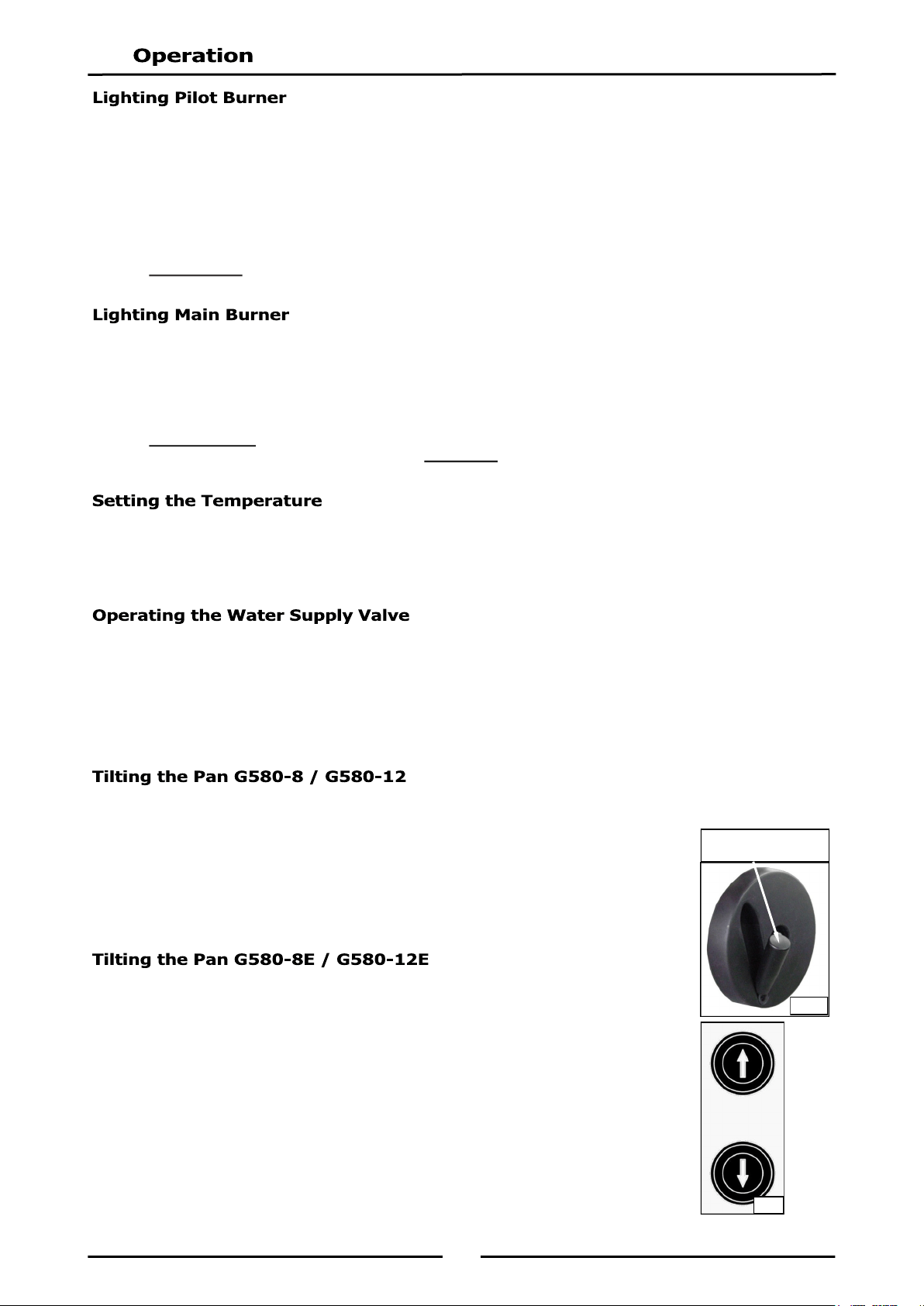
1. To tilt pan, ensure water valve is in closed position.
2. Open bratt pan lid to raised position.
3. Flip out stored handle and lock into operating position.
4. Rotate handwheel clockwise to tilt bratt pan. If main burners are operating,
these will automatically turn ‘Off’ as pan is raised.
5. With bratt pan returned to its ‘Down’ position, main burners will re-ignite.
NOTE: Bratt pan lid must be raised before lifting pan to avoid damage to
appliance.
1. To tilt pan, ensure water valve is in closed position.
2. Open bratt pan lid to raised position.
3. Depress pan tilt control ‘UP’ or ‘DOWN’ switches on front panel and hold pan
tilt control switch depressed until pan has reached desired position. If main
burners are operating, these will automatically turn ‘Off’ as pan is raised.
4. Releasing switch will stop tilt operation and pan will rest in chosen position.
5. With bratt pan returned to its ‘Down’ position, burners will re-ignite.
Pull Out Stored Handle
Fig 6
Fig 7

17
1. To turn bratt pan to ‘PILOT’ burner position, set gas control knob to ‘PILOT’ position. Main burner
will turn ‘OFF’ and pilot burner will remain lit.
2. To turn bratt pan ‘OFF’ completely, rotate gas control knob to ‘OFF’ position by depressing and
turning gas control knob clockwise. Pilot burner will extinguish completely.
3. Turn ‘OFF’ electrical power to bratt pan at mains supply otherwise ignitor will continually attempt to
ignite pilot.
NOTE: If gas supply is turned ‘OFF’ at mains supply and gas control knob on control panel is
left in pilot position, with electrical power still ‘ON’ at bratt pan, ignitor will continue to
operate and attempt to ignite pilot. Ensure that electrical power is also turned ‘OFF’ at
mains supply.
IMPORTANT:
Should any abnormal operation like;
- ignition problems,
- abnormal burner flame,
- burner control problems,
- partial or full loss of burner flame in normal operation, be noticed, appliance requires IMMEDIATE
service by a qualified service person and should not be used until such service is carried out.
18
Clean bratt pan regularly. A clean bratt pan looks better, will last longer and will perform better.
A dirty bratt pan will hinder transfer of heat from cooking surface to food. This will result in loss of
cooking efficiency.
NOTE:
DO NOT clean appliance using high pressure water or steam jets.
DO NOT pour water directly over appliance.
DO NOT use wire brushes. Clean pan regularly after each use.
DO NOT use combustible liquids to clean appliance.
DO NOT use harsh abrasive detergents, sharp scrapers, strong solvents or caustic
detergents as they will damage appliance.
DO NOT use any chloric or bleaching detergents to clean appliance.
DO NOT use saline or sulfuric acid preparations for descaling appliance.
Ensure protective gloves are worn during cleaning.
Clean pan regularly after each use.
Clean interior of pan regularly after each use. Do not use wire brushes on pan. Clean using a mild
detergent and a hot water solution using soft cloth or a soft bristled brush. Dry appliance thoroughly using
a dry clean cloth.
Clean exterior of bratt pan using a mild detergent and a hot water solution using soft cloth or a soft bristled
brush.
Clean bratt pan control panel using a soft cloth moistened with a solution of mild detergent and hot water.
DO NOT USE EXCESSIVE WATER. Dry control panel thoroughly using a dry clean cloth.
Clean interior and exterior of bratt pan using a mild detergent and a hot water solution using soft cloth or a
soft bristled brush. Do not use wire brushes on pan. Dry appliance thoroughly using a dry clean cloth.
19
NOTE:
If bratt pan usage is very high, we recommend that weekly cleaning procedure is
carried out more frequently.
Ensure that protective gloves are worn during cleaning.
DO NOT use harsh abrasive detergents, strong solvents, sharp scrapers or caustic
detergents as they will damage surface of bratt pan.
DO NOT use water on burners while they are still hot as cracking may occur. Allow
these items to cool and remove for cleaning.
DO NOT clean burners in a dishwasher.
Clean bratt pan control panel using a soft cloth moistened with a solution of mild detergent and hot water.
DO NOT USE EXCESSIVE WATER. Dry control panel thoroughly using a dry clean cloth.
Thoroughly clean interior and exterior of bratt pan regularly. Do not use wire brushes on pan. Clean using
a mild detergent and a hot water solution using soft cloth or a soft bristled brush. Dry appliance
thoroughly using a dry clean cloth.
NOTE: To prevent rust forming on steel components, ensure that detergent or cleaning
material has been entirely removed after each cleaning process.
Stainless Steel Surfaces
a. Clean interior and exterior surfaces of bratt pan with hot water, a mild detergent solution and a
soft scrubbing brush. Note that gas control knobs are a push fit onto gas and water control valve
spindles and can be removed to clean front of control panel.
b. Baked on deposits or discolouration may require a good quality stainless steel cleaner or stainless
steel wool. Always apply cleaner when appliance is cold and rub in direction of grain.
c. It should not be necessary to remove manual tilt mechanism handwheel for cleaning purposes.
d. Dry all components thoroughly with a dry cloth and polish with a soft dry cloth.
e. To remove any discolouration, use an approved stainless steel cleaner or stainless steel wool.
Always rub in direction of grain.
NOTE: All maintenance operations should only be carried out by a qualified service person.
To achieve the best results, cleaning must be regular and thorough and all controls and mechanical parts
should be checked and adjusted periodically by a qualified service person. If any small faults occur, have
them attended to promptly. Don't wait until they cause a complete breakdown. It is recommended that
the appliance is serviced every 6 months.

20
Igniter not sparking or sparking
intermittently.
No power to appliance.
No power to ignitor circuit.
Short in high tension lead.
Spark arc can be seen at
electrode insulator, rather than
at electrode tip.
Check power supply to
appliance.
Check power to ignitor circuit.
Check continuity through ignitor
switch located on gas control and
wiring to ignitor is secure. If this
is correct, replace ignitor.
Replace high tension lead.
Replace electrode.
Call service provider.
NOTE: If ignition system fails, pilot can be manually lit in interim until piezo circuit is
repaired. A standard taper torch, matches or lighter can be used to manually light
burner.
Pilot burner will not light / stay
alight.
Thermocouple connection loose.
Thermocouple faulty.
Pilot flame too small.
- Gas pressure too low.
- Partially blocked pilot injector.
Check gas control valve.
Check thermocouple connection
and repair.
Replace thermocouple.
Adjust pilot flame as shown in
'Gas Specifications'.
Gas control valve faulty, replace.
Call service provider.
Delay in pilot burner igniting main
burner.
Incorrect operating pressure
Incorrect supply pressure.
Pilot flame adjustment incorrect.
Pilot burner injector, wrong size.
Faulty gas control valve.
Check operating pressure.
Check supply pressure.
Adjust pilot flame as shown in
'Gas Specifications'.
Fit correct size pilot burner
injector.
Replace gas control valve.
Call service provider.
Ignitor sparking continuously. If gas supply is turned ‘OFF’ at
mains supply with gas control
knob left in ‘Pilot’ position, with
electrical power left ‘ON’ at mains,
ignitor will continue to operate
and attempt to ignite pilot.
Check gas control knob is turned
to ‘OFF’ position and electrical
power has been turned ‘OFF’ at
mains.
Call service provider.
This section provides an easy reference guide to the more common problems that may occur during
operation of your equipment. The fault finding guide in this section is intended to help you correct, or at
least accurately diagnose problems with your equipment.
Although this section covers the most common problems reported, you may encounter a problem not
covered in this section. In such instances, please contact your local authorised service agent who will
make every effort to help you identify and resolve the problem. Please note that the service agent will
require the following information:-
Model Trade Name and Serial Number of Appliance. (both can be found on Technical
Data Plate located on appliance.

21
Over-temperature thermostat cuts
out
Over-temperature thermostat
faulty.
Control thermostat not
maintaining set temperature.
a. Thermostat out of
calibration.
b. Thermostat does not open on
temperature rise.
Thermostat opens on
temperature rise but control
valve does not respond.
If main burners cut out and
power indicator light also drops
below 320ºC, replace over-
temperature thermostat.
Check continuity through
thermostat leads, on
temperature rise. If circuit does
not open, replace thermostat.
Check connections on gas
control are correct. If correct,
replace gas control valve.
Call service provider.
Main Burners do not ignite Check power is supplied to unit.
Check pan is flat and that tilt
microswitch is closed.
Check thermostat setting is
correct and gas control knob on
main burner is set to 'ON'
position.
Turn ‘On’ power.
Adjust microswitch so that micro-
switch is activated when pan is
fully down in flat (cooking
position).
Call service provider.
No pan filling water available.
(Manual water fill valve has an
electrical solenoid isolating valve
fitted to supply side of water
supply plumbing in appliance.
Shut-off valve only opens water
supply to manual valve when pan
is in ‘DOWN’ position.
With the pan in the down
position and main water supply
‘ON’ and manual water control
valve set to max flow, check
solenoid valve has electrical
power across its coil terminals.
If solenoid coil has power, but no
water available on turning manual
valve, check coil for open circuit,
short circuit and for solenoid coil
burn-out.
If solenoid coil is satisfactory,
disconnect water connection and
check inlet filter screen for foreign
matter blockage.
If there is no voltage to solenoid
coil.
Replace solenoid.
Clean and refit inlet filter.
Check water valve microswitch.
Check for electrical fault in pan
lift microswitch circuit. A fault
here is likely to also cause main
burner to fail.
Call service provider.
22
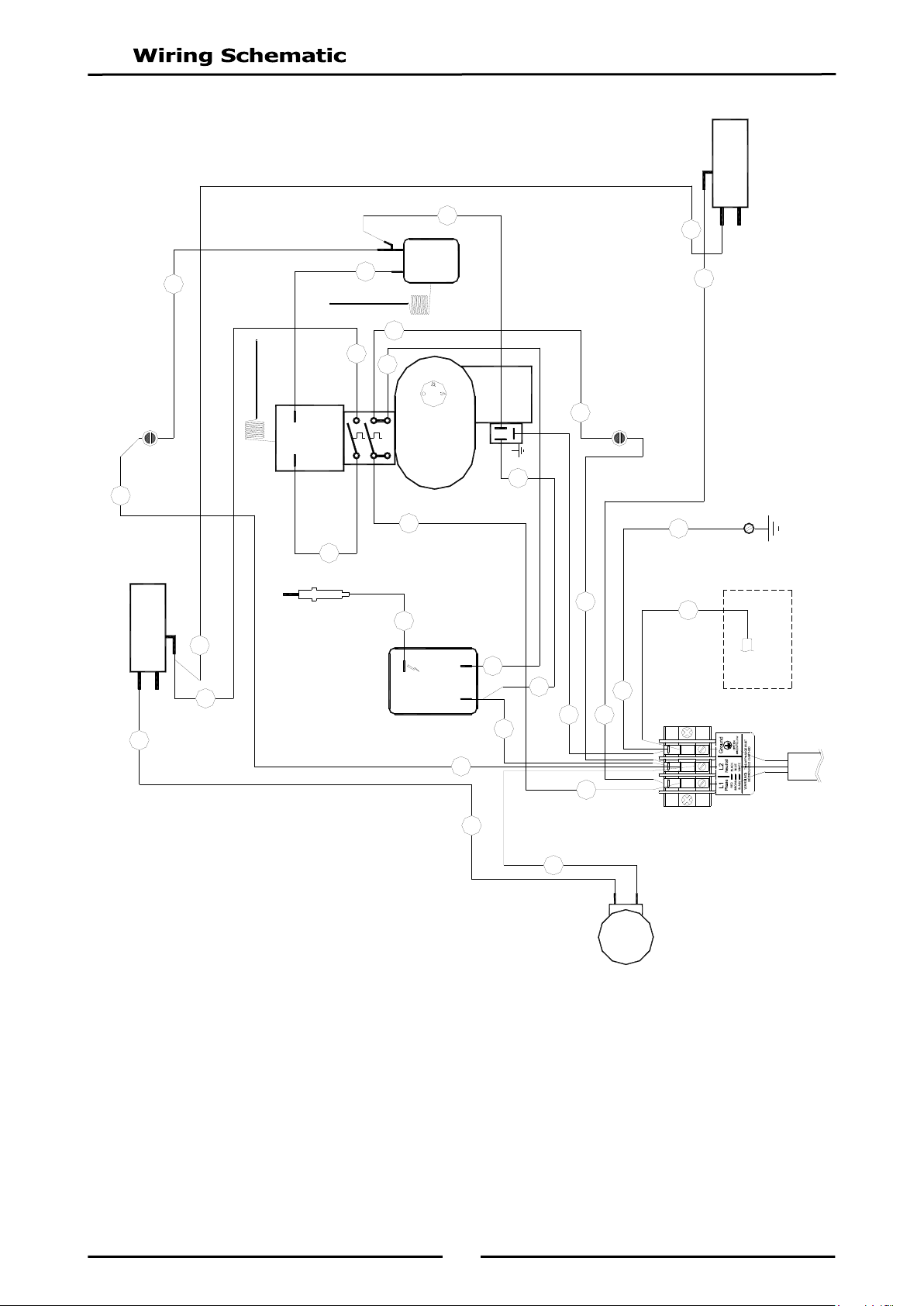
CONNECTION
SPARK BOX
SEE NOTE ON
1
1
2
WATER
SOLENOID
020851
THERMOSTAT
024774
228341 PILOT BURNER
AND IGN. ELECTRODE
IGNITOR
228191
WATER
MICROSWITCH
003004
TERMINAL BLOCK
013586
NEON GREEN
227962
NEON AMBER
227963
SWITCH
228999
GAS
CONTROL
227830
OVERTEMP
025400
PAN DOWN
MICROSWITCH
024802
CONTROL PANEL
E
2
1
P2
P1
2
10
8
7
13
3
4
6
5
15
1
20
9
14
19
17
11
12
COM
NO
NC
COM
NC
NO
13
2
3
16
9
4
1
15
EARTH STUD
18
1
2
11
SEE PLUG
ORIENTATION
10
18
G580-8 / G580-12 (Manual Tilt Models)
23
N/C
N/O
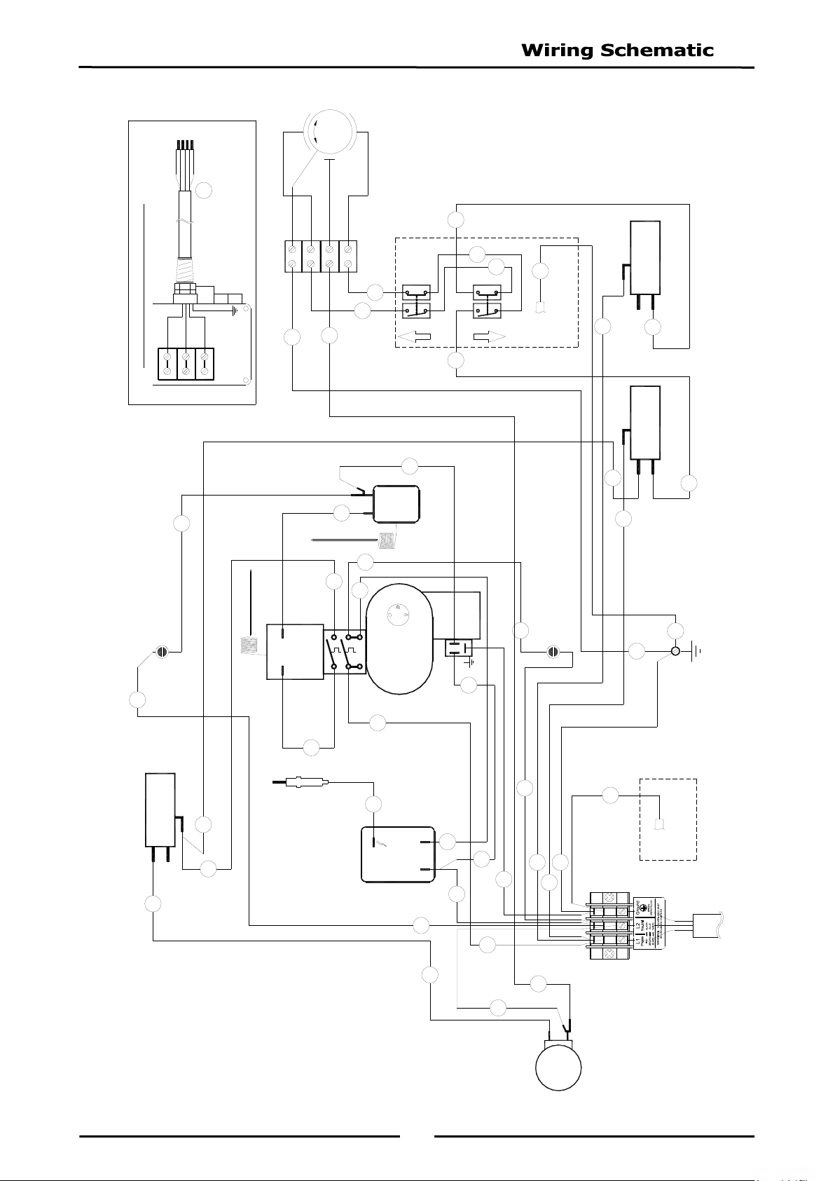
MOTOR TERMINATION BOX, WIRING DETAIL
N/O
CONNECTION
SPARK BOX
SEE NOTE ON
1
N/C
OVERTEMP
025400
PAN DOWN
MICROSWITCH
024802
PAN UP
MICROSWITCH
024802
LH COVER PANEL
E
CONTROL PANEL
E
2
1
P2
P1
Motor
WHITE
RED
BLUE
GREEN
U2
W2
V2
RED
BLUE
WHITE
GREEN
17
14
29
13
16
2
12
15
3
24
11
9
8
20
4
5
7
6
22
1
30
10
21
27
28
25
18
19
31
COM
NO
NC
COM
NC
NO
1
2
WATER
SOLENOID
020851
THERMOSTAT
024774
228341 PILOT BURNER
AND IGN. ELECTRODE
IGNITOR
228191
WATER
MICROSWITCH
003004
TERMINAL BLOCK
013586
NEON GREEN
227962
NEON AMBER
227963
SWITCH
228999
GAS
CONTROL
227830
COM
NC
NO
20
28
29
3
2
12
15
4
24
23
10
5
1
22
TERMINAL BLOCK
025950
EARTH STUD
26
1
2
18
SEE PLUG
ORIENTATION
11
G580-8E / G580-12E (Electric Tilt Models)
24
NOTE:
These conversions should only be carried out by qualified persons. All connections
must be checked for leaks before re-commissioning appliance.
Adjustment of components that have adjustments / settings sealed (e.g. paint
sealed) should only be adjusted in accordance with the following instructions and
should be re-sealed before re-commissioning this appliance.
For all relevant gas specifications refer to the table at rear of this section.
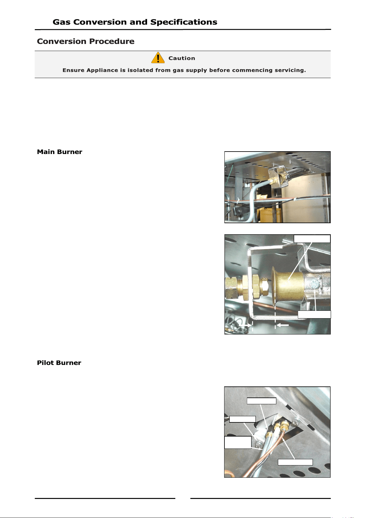
Carry out the following actions:-
Remove hand wheel (with pan in lowered position)
(G580-8 & G580-12 models only).
Remove gas and water control knobs.
Remove front control panel.
Remove large front right hand cover panel.
1. Refit hand wheel to allow pan to be raised / lowered during
gas conversion procedure. (G580-8 & G580-12 models
only).
2. Remove main burner injectors and replace with correct size
injectors as shown in ‘Gas Specification Tables’ at rear of
this section.
3. Ensure aeration sleeve is adjusted to measurements shown
in ‘Gas Specification Tables’.
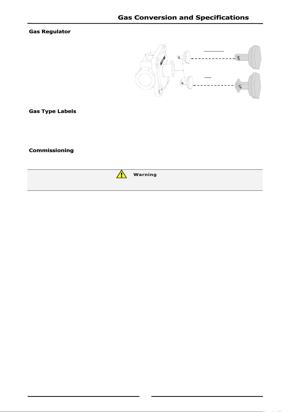
1. Disconnect the following:-
Pilot supply gas tube to pilot burner.
2. Remove pilot injector and replace with correct size injector
as shown in ‘Gas Specification’ table at rear of this section.
3. Refit the following:-
Pilot supply tube to pilot burner.
Lower bratt pan, (G580-8 & G580-12 models only).
Refit large front right hand cover panel.
Refit front control panel.
Refit gas and water control knobs.
Pilot Burner
Piezo Igniter
Thermocouple
Pilot Supply
Tube
H
Aeration Sleeve
Clamp Screw
25
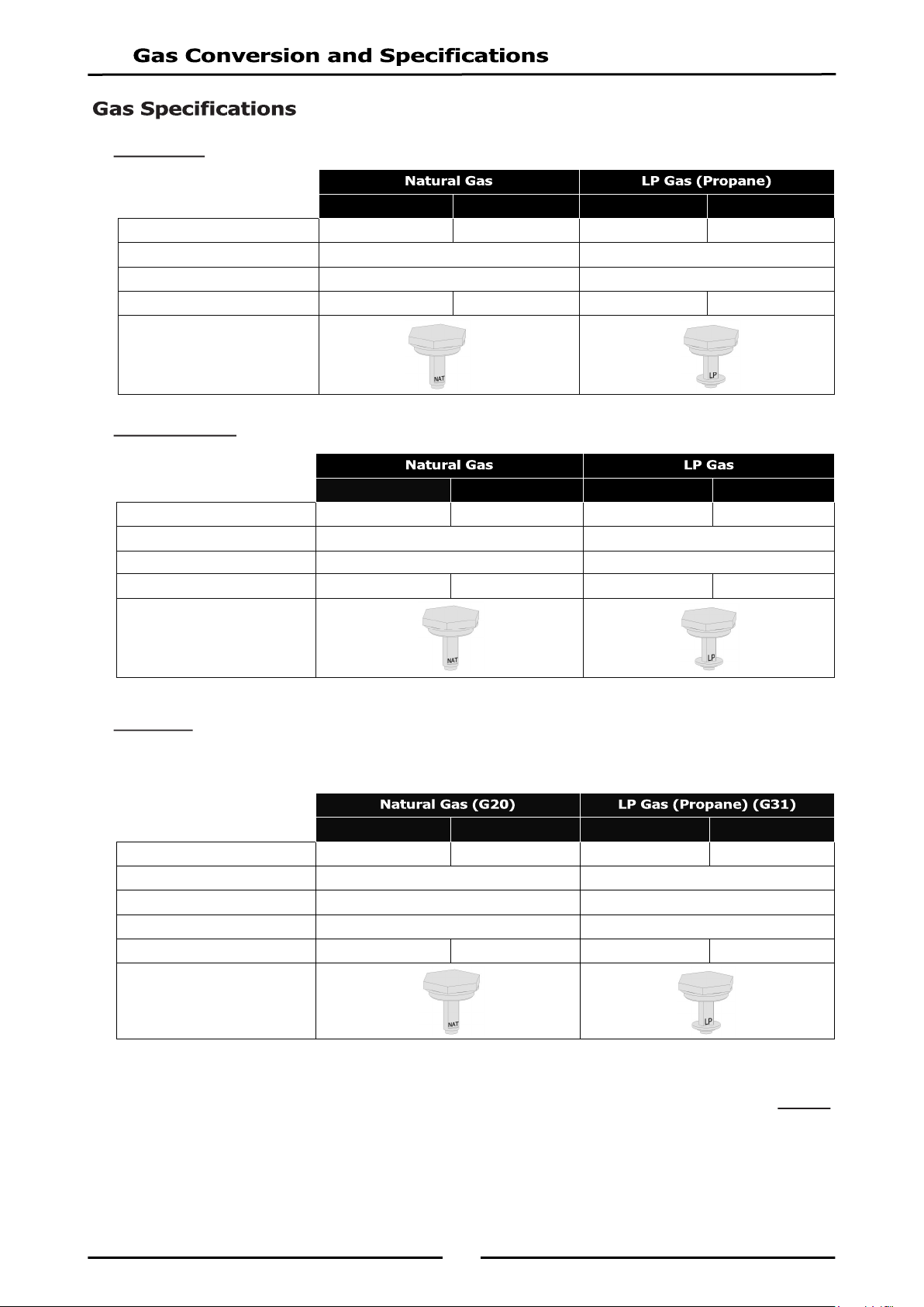
NOTE, Pin rotated
for Natural Gas
NOTE, Pin rotated
for LPG
NOTE: Gas regulator supplied is
convertible between Natural
Gas and LP Gas, but it’s outlet
pressure is fixed ex-factory and
is NOT to be adjusted.
On completion of gas conversion, replace gas type labels located at:-
- Rear of unit, above gas connection.
- Beside rating plate.
Before leaving installation;
1. Check all gas connections for leakage using soapy water or other gas detecting equipment.
2. Carry out a ‘Commissioning’ check of appliance as shown in Installation Section of this manual.
3. Ensure any adjustments done to components that have adjustments / settings paint sealed are to be
re-sealed.
NOTE: If for some reason it is not possible to get appliance to operate correctly, shut ‘Off’ gas
supply and contact supplier of this appliance.
DO NOT USE A NAKED FLAME TO CHECK FOR GAS LEAKAGES.
26
- Australia:
- New Zealand:
- UK Only:
Category: II
2H3P.
Flue Type: A
1.
NOTE:
* - Measure burner operating pressure at gas control outlet test point with burner
operating at ‘High’ setting. Operating pressure is ex-factory set through appliance
regulator and is not to be adjusted, apart from when carrying out gas conversion, if
required. (Refer to ‘Gas Conversion’ section for details).
G580-8 / 8E G580-12 / 12E G580-8 / 8E G580-12 / 12E
Main Burner Injector Ø 4.30mm Ø 5.20mm Ø 2.50mm Ø 2.80mm
Pilot Burner Injector 0.35 0.20
Aeration Clearance (H) 30mm 30mm
Burner Operating Pressure (*) 0.76kPa 0.60kPa 2.5kPa 2.4kPa
Gas Regulator Cap Screw
G580-8 / 8E G580-12 / 12E G580-8 / 8E G580-12 / 12E
Main Burner Injector Ø 4.30mm Ø 5.20mm Ø 2.50mm Ø 2.80mm
Pilot Burner Injector 0.35 0.20
Aeration Clearance (H) 30mm 30mm
Supply Pressure 20mbar 37mbar
Burner Operating Pressure (*) 7.5mbar 6.0mbar 25.7mbar 25.5mbar
Gas Regulator Cap Screw
G580-8 / 8E G580-12 / 12E G580-8 / 8E G580-12 / 12E
Main Burner Injector Ø 4.30mm Ø 5.20mm Ø 2.50mm Ø 2.80mm
Pilot Burner Injector 0.35 0.20
Aeration Clearance (H) 30mm 30mm
Burner Operating Pressure (*) 0.76kPa 0.60kPa 2.5kPa 2.4kPa
Gas Regulator Cap Screw
27
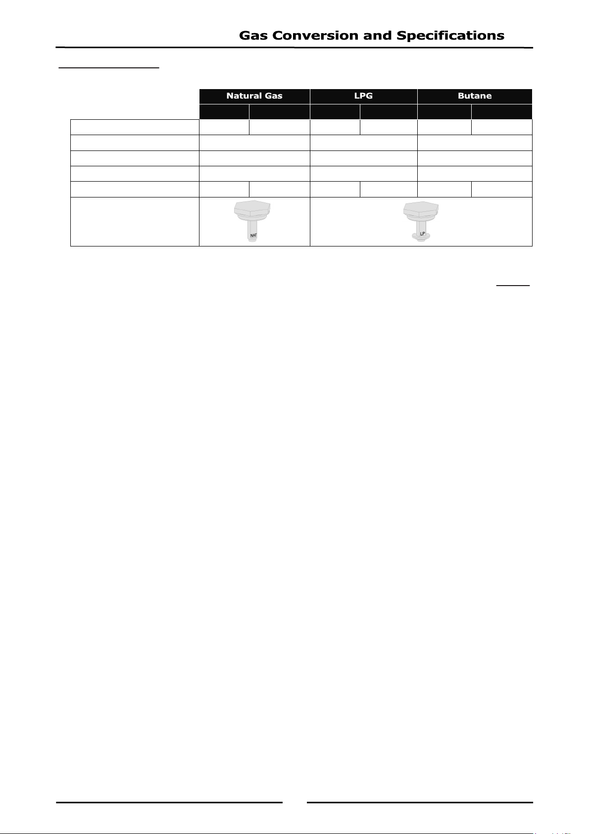
- All Other Markets:
NOTE:
* - Measure burner operating pressure at gas control outlet test point with burner
operating at ‘High’ setting. Operating pressure is ex-factory set through appliance
regulator and is not to be adjusted, apart from when carrying out gas conversion, if
required. (Refer to ‘Gas Conversion’ section for details).
G580-8 / 8E G580-12 / 12E G580-8 / 8E G580-12 / 12E G580-8 / 8E G580-12 / 12E
Main Burner Ø 4.30mm Ø 5.20mm Ø 2.50mm Ø 2.80mm Ø 2.40mm Ø 2.60mm
Pilot Burner 0.35 0.20 0.20
Aeration Clearance 30mm 30mm 30mm
Supply Pressure 1.13 - 3.40 kPa 2.75 - 4.50 kPa 2.75 - 4.50 kPa
Burner Operating Pressure (*) 0.76 kPa 0.60 kPa 2.5kPa 2.4kPa 2.5kPa 2.4kPa
Gas Regulator Cap Screw

28
Replacement Parts List
When ordering replacement parts, please quote part number and description as listed below. If part
required is not listed below, request part by description and quote Model and Serial Number which is
shown on rating plate.
Bratt Pan
228708 Main Burner (G580-8 / G580-8E).
228709 Main Burner (G580-12 / G580-12E).
038430 Burner Injector Ø 4.30mm - Natural Gas (G580-8 / G580-8E).
038520 Burner Injector Ø 5.20mm - Natural Gas (G580-12 / G580-12E).
038250 Burner Injector Ø 2.50mm - LPG (G580-8 / G580-8E).
038280 Burner Injector Ø 2.80mm - LPG (G580-12 / G580-12E).
038250 Burner Injector Ø 2.40mm - Butane (G580-8 / G580-8E).
038280 Burner Injector Ø 2.60mm - Butane (G580-12 / G580-12E).
228854 Pilot Burner Kit.
026488 Pilot Injector 0.35 - Natural Gas.
018692 Pilot Injector 0.20 - LPG / Butane.
020253 Thermocouple.
235421 H.T Lead Kit.
228191 Ignitor.
228706 Gas Control Assembly Kit.
229355 Selector Switch c/w Insulator.
013586 Terminal Block.
025950 Terminal Block (Motor).
024774 Thermostat 50°C - 320°C.
025400 Over-Temp Thermostat.
227963 Indicator Neon (Orange).
228922 Indicator Neon (White).
024802 Microswitch (Bratt Pan Raise - Lower).
003004 Microswitch (Water Valve).
242085 Water Valve Kit (incl. Valve, Lever and Bracket)
020851 Water Solenoid Valve.
227841 Lid Handle - 650mm (G580-8 / G580-8E Models Only).
227847 Lid Handle - 830mm (G580-12 / G580-12E Models Only).
228716 Lid Hinge Spring Kit.
227521 Tensioner Barrel.
240460 Gas Control Knob (1 to 10 Graduations).
227382 Water Control Knob.
227857 Electric Motor (8E & 12E Models Only).
020043 Bearing & Housing.
228123 Handwheel.
228117 Handwheel Spacer Bush.
044400 Key Woodruff -
7
/
8
" x
5
/
32
".
044066 Handle Nut - M16 x 2.
227850 Leg 150mm (Adjustable).
228531 Regulator (Natural Gas / LP Gas [Propane] convertible) - ¾” BSP F/F.
IMPORTANT:

29
Gas Conversion Kits
Accessories
228798 Plinth Kit 900mm.
228802 Plinth Kit 1200mm.
G580-8 / 8E 232041 232040 232042 232041 232040
G580-12 / 12E 232045 232044 232046 232045 232044