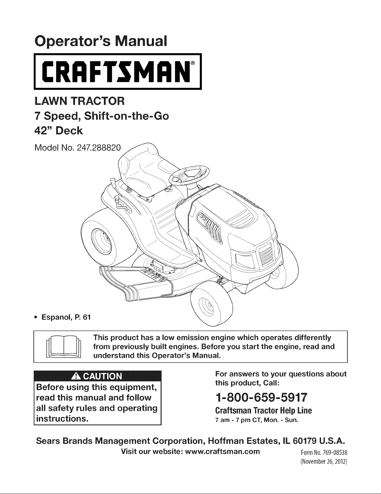
perator's
I:RnFrSMRN°
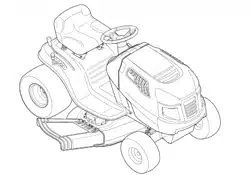
LAWN TRACTOR
7 Speed, Shift-on=the=Go
42" Deck
Model No. 247.288820
• Espanol, P. 61
This product has a low emission engine which operates differently
from previously built engines. Before you start the engine, read and
understand this Operator's Manual.
Before using this equipment,
read this manual and follow
all safety rules and operating
instructions.
For answers to your questions about
this product, Call:
1-800=659=5917
Craftsman Tractor Help Line
7 am = 7 pm CT, Mort. =Sun.
Sears Brands Management Corporation, Hoffman Estates, IL 60179 U.S.A.
Visit our website: www.craftsman.com FormNo.769-08538
(November26,2012)
Warranty Statement .......................................................... 2
Safety Instructions ............................................................ 3
Slope Gauge ..................................................................... 8
Assembly ........................................................................... 9
Operation ........................................................................ 11
Service and Maintenance .............................................. 17
Off-Season Storage ........................................................ 27
Troubleshooting .............................................................. 28
Labels ............................................................................. 29
Parts List ......................................................................... 30
Espafiol ............................................................................ 61
Service Numbers ............................................. Back Cover
CRAFTSMAN FULL WARRANTY
FORTWOYEARSfromthe dateof purchase,all non-expendablepartsof this ridingequipmentarewarrantedagainstany defectsin materialor
workmanship.A defectivenon-expendablepartwill receivefree in-homerepairor replacementif repairis unavailable.
BATTERYLIMITEDWARRANTY
FOR90 DAYSfromthe dateof purchase,the battery(an expendablepart)of this ridingequipmentis warrantedagainstanydefectsin materialor
workmanship.A newbatterywill be suppliedfreeof charge.Youare responsiblefor the laborcostof batteryinstallation.
ADDITIONALLIMITEDWARRANTIES
In the followingadditionalwarranties,you are responsibleforthe laborcost of partinstallationafterthe secondyearfromthe dateof purchase.
FORFIVEYEARSfromthedateof purchase,the frameof this ridingequipmentis warrantedagainstanydefects in materialor workmanship.A
newframewill be suppliedfreeof charge.
FORTENYEARSfromthe dateof purchase,the front axleof thisriding equipmentiswarrantedagainstany defectsin materialorworkmanship.
A newfrontaxle will be suppliedfreeof charge.
FORASLONGASIT ISUSEDbytheoriginalownerafterthetenthyearfromthedateof purchase,thecastironfrontaxle(if equipped)ofthis riding
equipmentiswarrantedagainstanydefectsin materialor workmanship.Withproofofpurchase,a newcastironfrontaxlewillbe suppliedfreeofcharge.
WARRANTYSERVICE
Forwarrantycoveragedetailsto obtainfree repairor replacement,call 1-800-659-5917orvisit the website: www.craftsman.com
In all casesabove,if part repairor replacementis impossible,the ridingequipmentwill be replacedfree of chargewiththe sameor an equivalent
model.
Allof the abovewarrantycoverageis void if thisridingequipmentis everusedwhileprovidingcommercialservicesor if rentedto anotherperson.
ThiswarrantycoversONLYdefectsin materialandworkmanship.Warrantycoveragedoes NOTinclude:
• Expendableparts(exceptbattery)thatcanwearout from normalusewithinthe warrantyperiod,includingbut not limitedto blades,spark
plugs,air cleaners,belts,andoil filters.
Standardmaintenanceservicing,oil changes,or tune-ups.
Tire replacementor repaircausedby puncturesfromoutsideobjects,suchas nails,thorns,stumps,or glass.
• Tireor wheelreplacementor repairresultingfrom normalwear,accident,or improperoperationor maintenance.
Repairsnecessarybecauseof operatorabuse,includingbutnot limitedto damagecausedby towingobjectsbeyondthe capabilityof the
ridingequipment,impactingobjectsthat bend theframe,axle assemblyorcrankshaft,or over-speedingthe engine.
Repairsnecessarybecauseof operatornegligence,includingbut not limitedto, electricaland mechanicaldamagecausedby improper
storage,failureto usethe propergradeandamountof engineoil, failureto keepthe deckclearof flammabledebris,orfailureto maintainthe
ridingequipmentaccordingto the instructionscontainedin theoperator'smanual.
• Engine(fuelsystem)cleaningor repairscausedbyfuel determinedto becontaminatedor oxidized(stale).In general,fuel shouldbe used
within30 daysof itspurchasedate.
• Normaldeteriorationandwearof the exteriorfinishes,or productlabelreplacement.
Thiswarrantygivesyou specificlegalrights,andyou mayalso haveotherrightswhichvary from stateto state.
Sears Brands ManagementCorporation, Hoffman Estates, IL 60179
Model Number:
EngineOil: SAE30 Serial Number:
Fuel: UnleadedGasoline Dateof Purchase:
SparkPlug: F6RTC(951-10292) Recordthe modelnumber,serialnumber,
anddateof purchaseabove.
© SearsBrands,LLC 2
Thissymbolpointsout importantsafetyinstructionswhich,if not
followed,couldendangerthepersonalsafetyand/orpropertyof
yourselfandothers. Readandfollowall instructionsin thismanual
beforeattemptingto operatethis machine.Failureto complywith
theseinstructionsmayresultin personalinjury.Whenyou seethis
symbol,HEEDITSWARNING!
CALIFORNIA PROPOSITION 65
EngineExhaust,someof itsconstituents,andcertainvehicle
componentscontainoremit chemicalsknownto Stateof California
to cause cancerandbirthdefectsorother reproductiveharm.
Batteryposts,terminals,and relatedaccessoriescontainleadand
leadcompounds,chemicalsknownto the Stateof Californiato
causecancerand reproductiveharm.Washhandsafter handling.
Thismachinewasbuiltto beoperatedaccordingto the safeopera-
tion practicesin this manual.As withanytypeof powerequipment,
carelessnessorerroron the partof the operatorcan resultin serious
injury.Thismachineis capableof amputatingfingers,hands,toes
andfeet and throwingdebris.Failureto observethe followingsafety
instructionscouldresultin seriousinjuryor death.
Your Responsibility--Restrict the useof thispowermachineto
personswho read,understandand follow thewarningsand instruc-
tionsin this manualand on the machine.
SAVE THESE INSTRUCTIONS!
GENERAL OPERATION
• Read,understand,andfollowall instructionson the machineand
in themanual(s)beforeattemptingto assembleandoperate.
Keepthis manualina safe placefor futureand regularreference
andfor orderingreplacementparts.
• Befamiliarwithall controlsandtheir properoperation.Knowhow
to stop the machineanddisengagethemquickly.
• Neverallowchildrenunder14yearsoldto operatethis machine.
Children14yearsoldand over shouldreadand understandthe
operationinstructionsandsafetyrulesin this manualandshould
betrainedandsupervisedbya parent.
• Neverallowadultsto operatethis machinewithoutproper
instruction.
• Tohelpavoidbladecontactor a thrownobjectinjury,keep
bystanders,helpers,childrenand pets at least75feetfromthe
machinewhile it is in operation.Stopmachineif anyoneenters
the area.
• Thoroughlyinspectthe area wherethe equipmentis to be used.
Removeallstones,sticks,wire,bones,toys,and otherforeign
objectswhichcouldbe pickedupand thrownby the blade(s).
Thrownobjectscan causeseriouspersonalinjury.
• Planyour mowingpatternto avoiddischargeof materialtoward
roads,sidewalks,bystandersandthe like.Also, avoiddischarg-
ingmaterialagainstawall orobstructionwhichmaycause
dischargedmaterialto ricochetbacktowardthe operator.
• Alwayswear safetyglassesor safetygogglesduring operation
andwhile performingan adjustmentor repairto protectyoureyes.
Thrownobjectswhich ricochetcancauseseriousinjuryto the
eyes.
• Wearsturdy,rough-soledwork shoesand close-fittingslacksand
shirts.Loosefittingclothesand jewelry canbe caughtin movable
parts.Neveroperatethismachinein bare feet or sandals.
• Beawareof the mowerandattachmentdischargedirectionand
do not pointit at anyone.Donot operatethe mowerwithoutthe
dischargecoverorentiregrass catcherin its properplace.
Donot put handsor feet near rotatingpartsor underthe cutting
deck. Contactwith the blade(s)can amputatehandsand feet.
A missingor damageddischargecovercan causeblade contact
or thrownobjectinjuries.
• Stoptheblade(s)whencrossinggraveldrives,walks,or roads
andwhile notcuttinggrass.
• Watchfor trafficwhenoperatingnear orcrossingroadways.This
machineis not intendedfor useonany public roadway.
• Donot operatethe machinewhile underthe influenceof alcohol
or drugs.
• Mowonly in daylightor good artificiallight.
Nevercarrypassengers.
• Disengageblade(s)beforeshiftinginto reverse.Backup slowly.
Alwayslookdownandbehindbeforeandwhile backingto avoida
back-overaccident.
3
• Slowdownbeforeturning.Operatethe machinesmoothly.Avoid
erraticoperationandexcessivespeed.
Disengageblade(s),setparkingbrake,stopengine and waituntil
the blade(s)come to a completestop beforeremovinggrass
catcher,emptyinggrass,uncloggingchute,removinganygrass or
debris,or makinganyadjustments.
Neverleavea runningmachineunattended.Alwaysturnoff
blade(s),setparkingbrake,stopengineand removekey before
dismounting.
Useextracare whenloadingorunloadingthe machineintoa
traileror truck. This machineshouldnot bedrivenupor down
ramp(s),becausethe machinecouldtip over,causingserious
personalinjury.The machinemustbe pushedmanuallyon
ramp(s)to loador unloadproperly.
Mufflerandenginebecomehotandcan causea burn.Do not
touch.
Checkoverheadclearancescarefullybeforedrivingunderlow
hangingtree branches,wires,door openingsetc.,wherethe
operatormaybe struckor pulledfrom the machine,whichcould
resultinseriousinjury.
Disengageallattachmentclutchesanddepressthe brakepedal
completelybeforeattemptingto start engine.
Yourmachineisdesignedto cut normalresidentialgrass of a
heightno morethan 10".Do not attemptto mowthroughunusually
tall,dry grass (e.g.,pasture)orpiles of dry leaves.Dry grass or
leavesmaycontactthe engineexhaustand/or build up on the
mowerdeckpresentinga potentialfire hazard.
Useonlyaccessoriesand attachmentsapprovedfor this machine
by the machinemanufacturer.Read,understandandfollowall
instructionsprovidedwiththe approvedaccessoryor attachment.
Fora list of approvedaccessoriesandattachments,call 1-800-
659-5917.
Dataindicatesthatoperators,age60 years and above,are
involvedin a largepercentageof riding mower-relatedinjuries.
Theseoperatorsshouldevaluatetheirabilityto operatethe riding
mowersafelyenoughto protectthemselvesandothersfrom
seriousinjury.
If situationsoccurwhicharenot coveredinthismanual,usecare
andgoodjudgment.
SLOPE OPERATION
Slopesare a majorfactorrelatedto loss of controlandtip-over
accidentswhichcan resultinsevereinjuryor death.All slopes require
extracaution.Ifyoucannotback up the slopeor if youfeel uneasyon
it, do not mowit.
Foryoursafety,use the SlopeGuide includedas partof this manual
to measureslopesbeforeoperatingthis machineona slopedor hilly
area. If the slopeis greaterthan15degreesas shownon the Slope
Guide,do notoperatethis machineon that area or seriousinjurycould
result.
Do:
o
Mowupand down slopes,not across.Exerciseextremecaution
whenchangingdirectionon slopes.
• Watchfor holes,ruts,bumps,rocks,orother hiddenobjects.
Uneventerraincouldoverturnthe machine.Tallgrasscan hide
obstacles.
Useslowspeed.Choosea lowenoughspeedsettingso that
you will nothaveto stopor shiftwhileon the slope.Tiresmay
lose tractionon slopeseventhoughthe brakesare functioning
properly.Alwayskeepmachinein gearwhen goingdownslopes
to take advantageof enginebrakingaction.
• Followthe manufacturer'srecommendationsfor wheelweightsor
counterweightsto improvestability.
Useextracarewithgrasscatchersor otherattachments.These
can changethe stabilityof the machine.
Keepallmovementonthe slopesslowandgradual.Do not make
suddenchangesin speedor direction.Rapidengagementor
brakingcouldcausethe frontof the machineto lift and rapidlyflip
overbackwardswhich couldcauseseriousinjury.
• Avoidstartingorstoppingona slope. If tires losetraction,disen-
gagethe blade(s)and proceedslowlystraightdownthe slope.
DoNot:
• Donot turnon slopesunlessnecessary;then, turnslowlyand
graduallydownhill,if possible.
• Donot mowneardrop-offs,ditchesor embankments.The mower
could suddenlyturnover if a wheelis overthe edgeof a cliff,
ditch,or if an edgecavesin.
• Donot try to stabilizethe machineby puttingyourfooton the
ground.
• Donot usea grass catcheron steepslopes.
• Donot mowon wetgrass.Reducedtractioncouldcausesliding.
• Donot attemptto coastdownhill.Over-speedingmaycausethe
operatorto lose controlof the machineresultingin seriousinjury
or death.
• Donot towheavypull behindattachments(e.g.loadeddumpcart,
lawn roller,etc.)on slopesgreaterthan5 degrees.Whengoing
down hill,the extraweighttendsto pushthe tractorandmay
causeyou to loosecontrol(e.g.tractormayspeedup, brakingand
steeringabilityare reduced,attachmentmayjack-knifeandcause
tractorto overturn).
4
CHILDREN
Tragicaccidentscanoccur ifthe operatoris notalert to the presence
of children.Childrenare often attractedto the machineandthe mowing
activity.Theydo notunderstandthe dangers.Neverassumethat
childrenwill remainwhereyou lastsawthem.
• Keepchildrenout of the mowingareaand inwatchfulcare of a
responsibleadultotherthanthe operator.
• Bealert and turnmachineoff ifa childentersthe area.
• Beforeandwhilebacking,lookbehindand downfor small
children.
Nevercarrychildren,evenwith the blade(s)shut off.Theymay
fall off andbe seriouslyinjuredor interferewith safe machine
operation.
• Useextremecarewhenapproachingblindcorners,doorways,
shrubs,treesor otherobjectsthat may block yourvisionof a child
whomay run intothe machine.
Toavoidback-overaccidents,alwaysdisengagethe cutting
blade(s)beforeshiftingintoReverse.If equipped,the "Reverse
CautionMode"(bladesoperatewhilemachineridesin reverse)
shouldnotbe usedwhenchildrenor othersarearound.
Keepchildrenawayfrom hotor runningengines.They cansuffer
burnsfroma hotmuffler.
• Removekeywhenmachineisunattendedto preventunauthorized
operation.
Neverallowchildrenunder 14 yearsof ageto operatethis machine.
Children14andovershouldreadand understandthe instructionsand
safeoperationpracticesin this manualand on the machineandshould
betrainedandsupervisedbyan adult.
TOWING
Towonlywith a machinethat hasa hitch designedfor towing.Do
not attachtowedequipmentexceptat the hitch point.
Followthe manufacturersrecommendationforweightlimitsfor
towedequipmentandtowingon slopes.
Neverallowchildrenor othersin or on towedequipment.
Onslopes,theweightof thetowedequipmentmaycauselossof
tractionandloss of control.
Alwaysuseextra cautionwhentowingwitha machinecapableof
makingtightturns (e.g."zero-turn"ride-onmower). Makewide
turnsto avoidjack-knifing.
Travelslowlyand allowextradistanceto stop.
Do notcoastdownhill.
SERVICE
SafeHandlingof Gasoline
Toavoidpersonalinjuryorpropertydamageuse extremecarein
handlinggasoline.Gasolineisextremelyflammableand the vaporsare
explosive.Seriouspersonalinjurycanoccur whengasolineis spilled
on yourselforyour clotheswhich can ignite.Washyourskin and
changeclothesimmediately.
• Useonly an approvedgasolinecontainer.
Neverfill containersinsidea vehicleoron a truckortrailer bed
witha plasticliner.Alwaysplacecontainerson the groundaway
fromyourvehiclebeforefilling.
Whenpractical,removegas-poweredequipmentfrom the truck
or trailerand refueliton theground.Ifthis isnot possible,then
refuelsuchequipmentona trailerwith a portablecontainer,rather
than froma gasolinedispensernozzle.
Keepthe nozzleincontactwiththe rim of the fueltank or
containeropeningat all timesuntilfuelingiscomplete.Donot use
a nozzlelock-opendevice.
Extinguishall cigarettes,cigars,pipesandothersourcesof
ignition.
• Neverfuel machineindoors.
Neverremovegascap or addfuelwhilethe engineis hotor run-
ning.Allowengineto coolat leasttwominutesbeforerefueling.
Neveroverfill fuel tank. Filltank to no morethan 1/2inchbelow
bottomof filler neckto allowspaceforfuel expansion.
• Replacegasolinecap and tightensecurely.
• Ifgasolineis spilled,wipeitoff the engineand equipment.Move
machineto anotherarea.Wait5 minutesbeforestartingthe
engine.
• To reducefire hazards,keepmachinefree of grass,leaves,or
otherdebrisbuild-up.Cleanup oilor fuel spillageandremoveany
fuel soakeddebris.
• Neverstorethe machineor fuelcontainerinsidewherethere isan
openflame,sparkor pilotlight as on a waterheater,spaceheater,
furnace,clothesdryeror othergasappliances.
Allowa machineto coolat leastfiveminutesbeforestoring.
GeneralService
• Neverrunanengineindoorsorinapoorlyventilatedarea.Engine
exhaustcontainscarbonmonoxide,anodorless,anddeadlygas.
• Beforecleaning,repairing,orinspecting,makecertainthe
blade(s)andallmovingpartshavestopped.Disconnectthespark
plugwireandgroundagainsttheenginetopreventunintended
starting.
• Periodicallychecktomakesurethebladescometocomplete
stopwithinapproximately(5)fivesecondsafteroperatingthe
bladedisengagementcontrol.Ifthebladesdonotstopwithinthe
thistimeframe,yourmachineshouldbeservicedprofessionally
byaSearsorotherqualifiedservicedealer.
• Checkbrakeoperationfrequentlyasitissubjectedtowearduring
normaloperation.Adjustandserviceasrequired.
• Checktheblade(s)andenginemountingboltsatfrequent
intervalsforpropertightness.Also,visuallyinspectblade(s)
fordamage(e.g.,excessivewear,bent,cracked).Replacethe
blade(s)withtheoriginalequipmentmanufacturer's(O.E.M.)
blade(s)only,listedinthismanual.Useofpartswhichdonot
meettheoriginalequipmentspecificationsmayleadtoimproper
performanceandcompromisesafety!
• Mowerbladesaresharp.Wrapthebladeorweargloves,anduse
extracautionwhenservicingthem.
• Keepallnuts,bolts,andscrewstighttobesuretheequipmentis
insafeworkingcondition.
• Nevertamperwiththe safetyinterlocksystemor othersafety
devices.Checktheir properoperationregularly.
• Afterstrikinga foreignobject,stop the engine,disconnectthe
sparkplugwire(s)and groundagainstthe engine.Thoroughly
inspectthe machinefor anydamage.Repairthe damagebefore
startingandoperating.
• Neverattemptto makeadjustmentsor repairsto the machine
whilethe engineis running.
• Grasscatchercomponentsandthe dischargecoverare subject
to wearanddamagewhich couldexposemovingparts or allow
objectsto bethrown.Forsafetyprotection,frequentlycheck
componentsand replaceimmediatelywith originalequipment
manufacturer's(O.E.M.)partsonly,listedinthis manual.Useof
partswhichdo not meetthe originalequipmentspecificationsmay
leadto improperperformanceand compromisesafety!
• Donot changethe enginegovernorsettingsor over-speedthe
engine.The governorcontrolsthe maximumsafeoperatingspeed
of the engine.
Maintainor replacesafetyandinstructionlabels,as necessary.
• Observeproperdisposallawsandregulationsfor gas,oil, etc.to
protecttheenvironment.
• Accordingto the ConsumerProductsSafetyCommission(CPSC)
andthe U.S.EnvironmentalProtectionAgency(EPA),this product
has an AverageUsefulLifeof seven(7) years,or 270 hours
of operation.At the endof the AverageUsefulLife,buy anew
machineor havethe machineinspectedannuallybya Searsor
otherqualifiedservicedealerto ensurethat all mechanicaland
safetysystemsareworkingproperlyandnot wornexcessively.
Failureto do so can resultinaccidents,injuriesor death.
DO NOT MODIFY ENGINE
Toavoid seriousinjuryor death,do notmodifyengine inanyway.
Tamperingwiththe governorsettingcanleadto a runawayengineand
causeit to operateat unsafespeeds.Nevertamper with factorysetting
of enginegovernor.
NOTICE REGARDING EMISSIONS
Engineswhicharecertifiedto complywithCaliforniaandfederal
EPAemissionregulationsfor SORE(SmallOffRoadEquipment)are
certifiedto operateon regularunleadedgasoline,andmayinclude
the followingemissioncontrol systems:EngineModification(EM)and
ThreeWay Catalyst(TWO)if so equipped.
SPARK ARRESTOR
Thismachineisequippedwith an internalcombustionengineand
shouldnot beusedon or near anyunimprovedforest-covered,
brushcoveredor grass-coveredlandunlesstheengine'sexhaust
systemis equippedwith a sparkarrestormeetingapplicablelocalor
statelaws (if any).
Ifa sparkarrestoris used,it shouldbe maintainedin effectiveworking
orderby the operator.Inthe Stateof Californiatheaboveis required
by law (Section4442of the CaliforniaPublicResourcesCode). Other
statesmayhavesimilarlaws.Federallaws applyonfederallands.
A sparkarrestorfor the muffleris availablethroughyournearestSears
PartsandRepairServiceCenter.
6
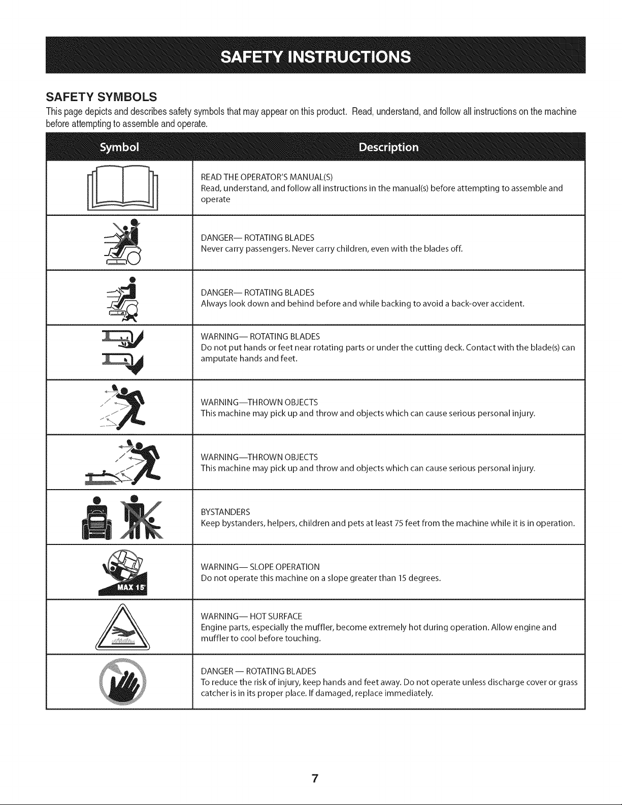
SAFETY SYMBOLS
Thispagedepictsand describessafety symbolsthat may appearonthis product. Read,understand,and follow all instructionson the machine
beforeattemptingto assembleand operate.
0
A
READ THE OPERATOR'S MANUAL(S)
Read, understand, and follow all instructions in the manual(s) before attempting to assemble and
operate
DANGER-- ROTATING BLADES
Never carry passengers. Never carry children, even with the blades off.
DANGER-- ROTATING BLADES
Always look down and behind before and while backing to avoid a back-over accident.
WARNING-- ROTATING BLADES
Do not put hands or feet near rotating parts or under the cutting deck. Contact with the blade(s) can
amputate hands and feet.
WARNING--THROWN OBJECTS
This machine may pick up and throw and objects which can cause serious personal injury.
WARNING--THROWN OBJECTS
This machine may pick up and throw and objects which can cause serious personal injury.
BYSTANDERS
Keep bystanders, helpers, children and pets at least 75 feet from the machine while it is in operation.
WARNING-- SLOPE OPERATION
Do not operate this machine on a slope greater than 15 degrees.
WARNING-- HOT SURFACE
Engine parts, especially the muffler, become extremely hot during operation. Allow engine and
muffler to cool before touching.
DANGER-- ROTATING BLADES
To reduce the risk of injury, keep hands and feet away. Do not operate unless discharge cover or grass
catcher is in its proper place. If damaged, replace immediately.
7
(OK)
15° Slope
X
(TOO STEEP)
15° Slope
'_. _ Figure1
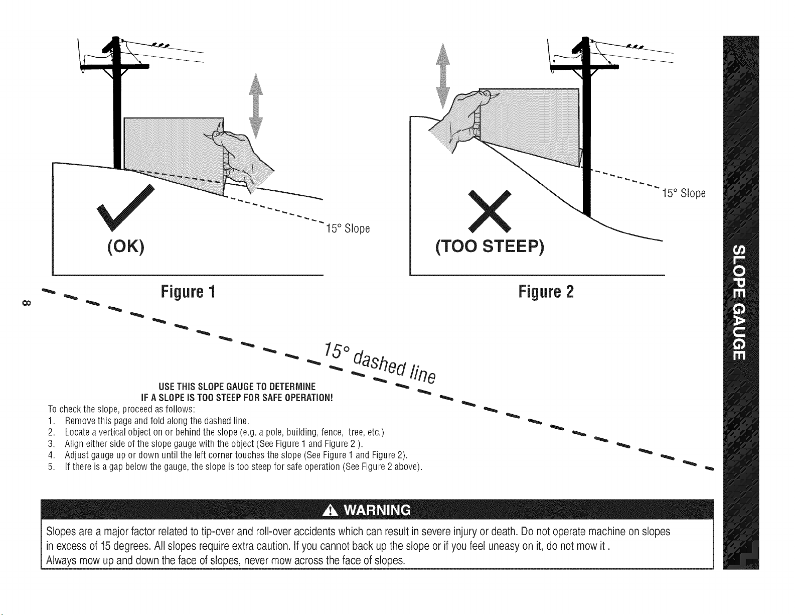
USETHISSLOPEGAUGETODETERMINE
IFA SLOPEIS TOOSTEEPFORSAFEOPERATION!
To checkthe slope,proceedas follows:
1. Removethis pageandfold along the dashedline.
2. Locatea verticalobject on or behindthe slope (e.g.a pole, building,fence, tree,etc.)
3. Align eitherside of the slope gaugewith the object (See Figure1 and Figure2 ).
4. Adjust gaugeup or down until the left cornertouchesthe slope (SeeFigure1and Figure2).
5.
15°
dashed line
If there is agap belowthe gauge,the slope is too steepfor safeoperation(SeeFigure2 above).
Figure2
Slopes are a majorfactor related to tip-over and roll-over accidents which can result in severe injury or death. Do not operatemachine on slopes
in excess of 15 degrees. All slopes require extra caution. If you cannot back up the slope or if you feel uneasy on it, do not mow it.
Always mow up and down the face of slopes, never mow across the face of slopes.
IM PORTANT: Yourtractorisshippedwith motoroil inthe engine.However,
youMUSTcheckthe oil levelbeforeoperating.Referto the Service& Maintenance
sectionforinstructionson checkingtheoil level.
Attaching the Battery Cables
CALIFORNIA PROPOSITION 65
Batteryposts,terminals,and relatedaccessoriescontain leadand lead
compounds,chemicalsknown to the Stateof Californiato causecancerand
reproductiveharm.Washhandsafter handling.
Shipping BraceRemoval
Makesurethe riding mower'sengineisoff, removethe ignition key,and
set the parkingbrake beforeremovingthe shipping brace.Referto the
Operaton sect on for nstruct ons on how to setthe park ng brake.
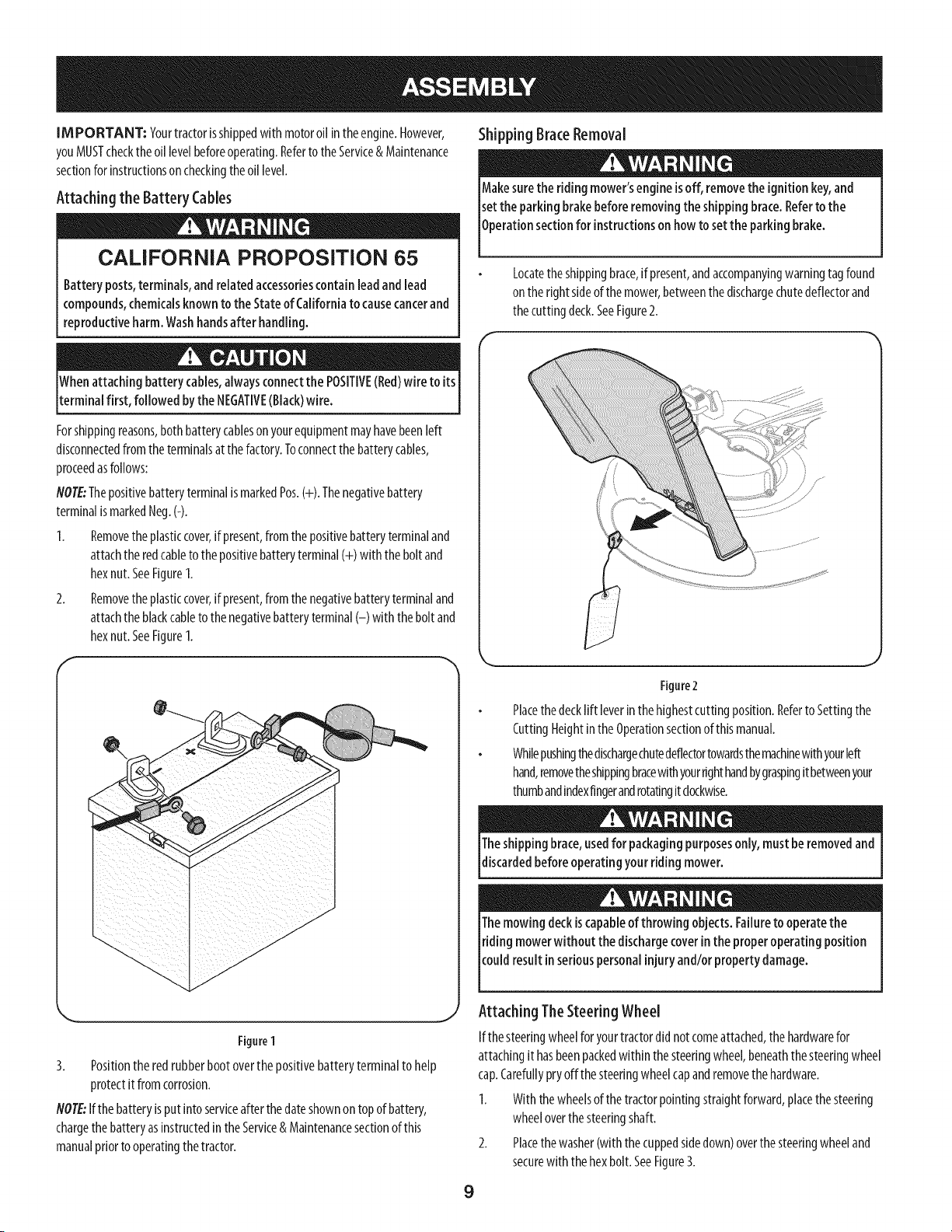
Locatetheshippingbrace,if present,andaccompanyingwarningtagfound
on therightsideof themower,betweenthedischargechutedeflectorand
thecuttingdeck.SeeFigure2.
Whenattaching battery cables,alwaysconnectthe POSITIVE(Red)wire to its
terminal first, followed bythe NEGATIVE(Black)wire.
Forshippingreasons,bothbatterycableson yourequipmentmayhavebeenleft
disconnectedfrom the terminalsat the factory.Toconnectthe batterycables,
proceedasfollows:
NOTE:ThepositivebatteryterminalismarkedPos.(+).Thenegativebattery
terminalismarkedNeg.(-).
1. Removetheplasticcover,ifpresent,fromthe positivebatteryterminaland
attachthe redcableto the positivebatteryterminal(+) with the bolt and
hexnut.SeeFigure1.
2. Removetheplasticcover,ifpresent,fromthe negativebatteryterminaland
attachthe blackcableto thenegativebatteryterminal(-) with thebolt and
hexnut.SeeFigure1.
f
/
/
/
/
/
Figure 1
3. Positionthe redrubberbootoverthe positivebatteryterminalto help
protectit fromcorrosion.
NOTE:Ifthe batteryisput intoserviceafterthe dateshownon topof battery,
chargethe batteryasinstructedin the Service& Maintenancesectionofthis
manualpriorto operatingthe tractor.
J
Figure2
Placethedecklift leverin the highestcutting position.Referto Settingthe
CuttingHeightinthe Operationsectionof thismanual.
Whilepushingthedischargechutedeflectortowardsthemachinewithyourleft
hand,removetheshippingbracewithyourrighthandbygraspingitbetweenyour
thumbandindexfingerandrotatingit clockwise.
9
Theshipping brace,usedfor packagingpurposesonly, must beremovedand
discardedbefore operatingyour ridingmower.
Themowing deckiscapableof throwing objects. Failureto operatethe
riding mowerwithout the dischargecoverin the proper operating position
cou d resut n set ouspersona njury and/or property damage.
Attaching TheSteering Wheel
Ifthe steeringwheelforyourtractordid notcomeattached,thehardwarefor
attachingit hasbeenpackedwithin thesteeringwheel,beneaththesteeringwheel
cap.Carefullypryoffthe steeringwheelcapandremovethehardware.
1. With the wheelsof the tractorpointingstraightforward,placethe steering
wheeloverthesteeringshaft.
2. Placethewasher(with the cuppedsidedown)overthesteeringwheeland
securewith thehexbolt.SeeFigure3.
F
\
Figure3
3.
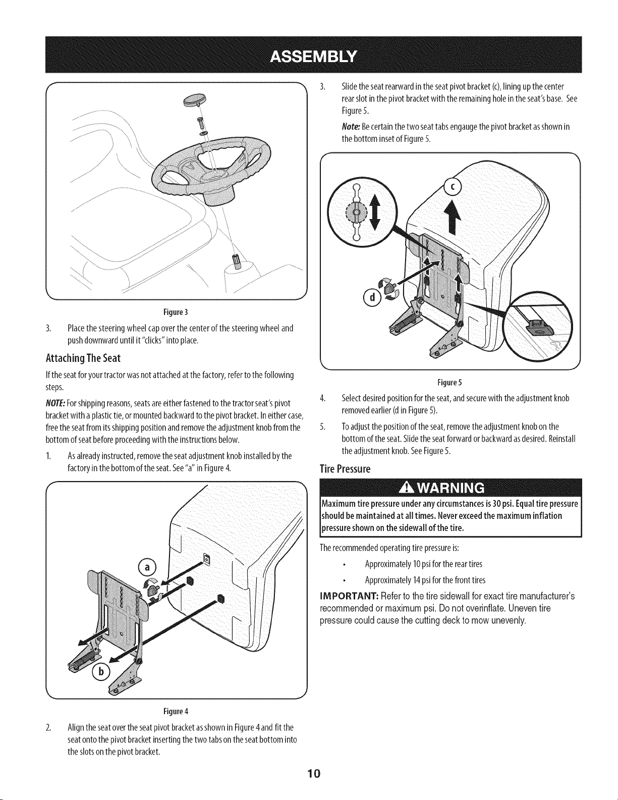
Placethesteeringwheel capoverthe centerof the steeringwheeland
pushdownwarduntil it "clicks"intoplace.
Attaching The Seat
If the seatforyourtractorwasnotattachedat the factory,referto the following
steps.
NOTE:Forshippingreasons,seatsareeitherfastenedto thetractorseat'spivot
bracketwith a plastictie, ormountedbackwardto thepivotbracket.Ineithercase,
freethe seatfrom its shippingpositionandremovethe adjustmentknobfromthe
bottomofseatbeforeproceedingwith theinstructionsbelow.
1. Asalreadyinstructed,removethe seatadjustmentknobinstalledbythe
factoryin the bottomoftheseat.See"a"inFigure4.
®
Slidethe seatrearwardin the seatpivotbracket(c),liningup the center
rearslotinthepivot bracketwith the remainingholeintheseat'sbase.See
FigureS.
Note:Becertainthe two seattabsengaugethe pivot bracketasshownin
thebottominsetof Figure5.
Figure5
4. Selectdesiredpositionfortheseat,andsecurewith the adjustmentknob
removedearlier(din Figure5).
5. Toadjustthe positionof theseat,removetheadjustmentknobon the
bottomof the seat.Slidetheseatforwardor backwardasdesired.Reinstall
theadjustmentknob.SeeFigure5.
Tire Pressure
Maximum tire pressureunderany circumstancesis30 psi. Equaltire pressure
shouldbe maintained at all times. Neverexceedthe maximum inflation
)ressureshown on the sidewallof the tire.
Therecommendedoperatingtirepressureis:
Approximately10psiforthereartires
Approximately14psiforthefronttires
IMPORTANT: Referto the tire sidewallfor exacttire manufacturer's
recommendedormaximumpsi.Donot overinflate.Uneventire
pressurecouldcausethe cuttingdeckto mowunevenly.
2.
Figure4
Alignthe seatoverthe seatpivot bracketasshownin Figure4andfit the
seatontothepivotbracketinsertingthe two tabsontheseatbottominto
theslotsonthepivotbracket.
10
H
A
c)
D
(3
F
E
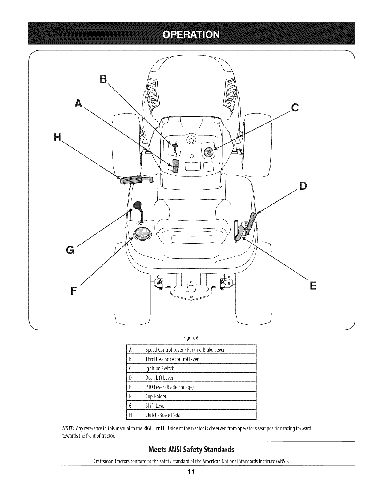
Figure6
A SpeedControlLever/ ParkingBrakeLever
B Throttle/chokecontrollever
C IgnitionSwitch
D DeckLift Lever
E PTOLever(BladeEngage)
F CupHolder
G Shift Lever
H Clutch-BrakePedal
NOTE:Anyreferenceinthis manualto theRIGHTorLEFTsideof thetractorisobservedfromoperator'sseatpositionfacingforward
towardsthefront of tractor.
Meets ANSISafety Standards
CraftsmanTractorsconformto the safetystandardofthe AmericanNationalStandardsInstitute(ANSI).
11
SpeedControlLever
Thespeedcontrollever,Moatedontheleft sideofthe tractor's
dashconsole,allowsyouto regulatethegroundspeedofthe lawn
tractor.Touse,depressthe dutch-brakepedalandmovethelever
outofthe parkingbrakenotchandforwardto increasethetractor's
groundspeed.Whenadesiredspeedhasbeenreached,releasethe
leverintoan appropriatenotchto maintainthat speed.
Toslowthe tractor'sgroundspeed,depressthedutch-brakepedal
andmovethe speedcontrolleverrearwardandreleaseit intoa
notch.
ParkingBrake
Tosetthe parkingbrake,fully depresstheclutch-brakepedal.Move
thespeedcontrolleverallthewaydownandintothe parkingbrake
position.Releasethe clutch-brakepedalto allowtheparkingbrake
to engage.
7_
2-
1=
(Q)
PARK
BRAKE
Toreleasetheparkingbrake,depressthe clutch-brakepedalandmovethe speed
controlleverout of thenotchesto the desiredposition.Releasethe speedcontrol
leverandtheclutch-brakepedal.
NOTE:Theparkingbrakemustbesetif theoperatorleavestheseatwith theengine
runningorthe enginewill automaticallyshutoff.
Throttle/Choke ControlLever
Thethrottle/chokecontrolleverislocatedon therightsideof the
tractor'sdashpanel.Thislevercontrolsthespeedof the engine
andwhen pushedall the wayforward,the chokecontrolalso.
Whensetinagivenposition,the throttlewill maintainauniform
enginespeed.
IMPORTANT:Whenoperatingthe tractorwiththecuttingdeck
engaged,thethrottle/chokecontrollevermustalwaysbe inthe
FAST(rabbit)position.
Ignition Switch
Thekeyswitch
moduleisusedto
startandstopthe
engine.Insertkey
intothe keyswitch
moduleandturn clockwiseto the
STARTposition.Releasethekeyinto
thenormalmowingpositiononce
enginehasstarted.Theheadlightswill
beactivatedautomatically.
Tostoptheengine,turn the ignitionkeycounterclockwiseto theSTOPposition.
IMPORTANT:Priorto operatingthe tractor,referto boththe"SafetyInterlock
System"and"StartingTheEngine"laterinthissectionof thismanualfordetailed
instructionsregardingthe IgnitionSwitchModule.
Neverleavearunningmachineunattended.AlwaysdisengagePTO(Blade
EngageLever),moveshift leverintoneutral position, set parking brake,
stopengineand removekeyto prevent unintendedstarting.
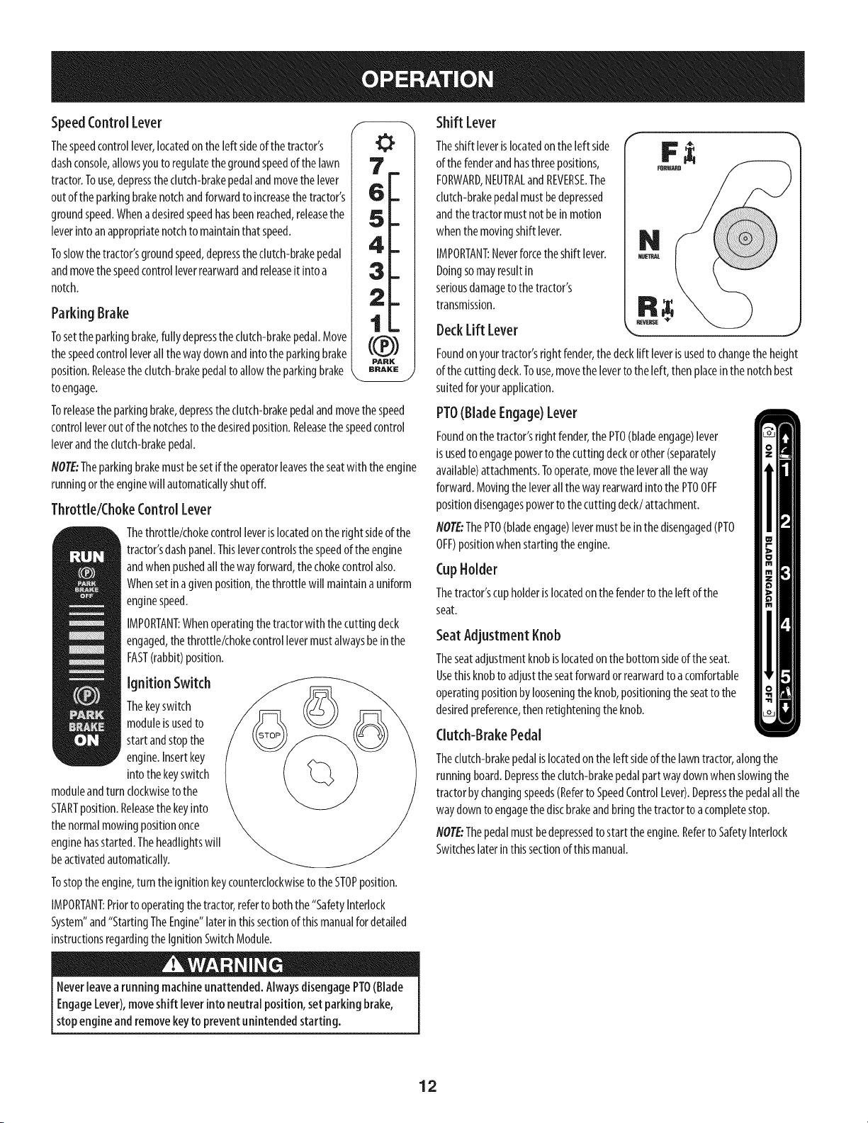
Shift Lever
Theshift leverislocatedon theleft side
of thefenderandhasthree positions,
FORWARD,NEUTRALandREVERSE.The
clutch-brakepedalmustbedepressed
andthetractormustnotbein motion
whenthemovingshift lever.
IMPORTANT:Neverforcetheshift lever.
Doingsomayresultin
seriousdamageto thetractor's
transmission.
DeckLift Lever
Foundon yourtractor'srightfender,thedecklift leverisusedto changethe height
of thecuttingdeck.Touse,movethe leverto theleft, thenplaceinthe notchbest
suitedforyourapplication.
PTO(Blade Engage)Lever
Foundon the tractor'srightfender,the PTO(bladeengage)lever
is usedto engagepowerto thecuttingdeckorother(separately
available)attachments.Tooperate,movethe leverall theway
forward.Movingthe leverall thewayrearwardintothe PTOOFF
positiondisengagespowerto thecutting deck/attachment.
NOTE"ThePTO(bladeengage)levermustbein the disengaged(PTO
OFF)positionwhenstartingtheengine.
CupHolder
Thetractor'scupholderislocatedon thefenderto theleft of the
seat.
Seat Adjustment Knob
Theseatadjustmentknobislocatedonthebottomsideof theseat.
Usethisknobto adjustthe seatforwardorrearwardto a comfortable
operatingpositionbylooseningtheknob,positioningthe seatto the
desiredpreference,thenretighteningtheknob.
Clutch-BrakePedal
Thedutch-brakepedalislocatedon theleft sideof the lawntractor,alongthe
runningboard.Depressthedutch-brakepedalpartwaydownwhen slowingthe
tractorbychangingspeeds(Referto SpeedControlLever).Depressthe pedalall the
waydownto engagethediscbrakeandbringthe tractorto acompletestop.
NOTE:Thepedalmustbedepressedtostart the engine.Referto SafetyInterlock
Switcheslaterin thissectionof thismanual.
12
Gasand Oil Fill-up
Oil
IMPORTANT:Yourtractorisshippedwith motoroil in the engine.However,you
MUSTchecktheoii levelbeforeoperating.Becarefulnot tooverfill.
Forinstructionsonhowto checkthe engineoil,referto CheckingTheEngineOilin
theServiceandMaintenancesectionof thismanual.
Gasoline
Thegasolinetank islocatedunderthe hood.Donotoverfill.
Useextreme carewhen handling gasoline.Gasolineisextremely flammable
andthe vaporsareexplosive.Neverfuel machineindoorsorwhile the
engineishotor running. Extinguishcigarettes,cigars,pipes,andother
sourcesof gnt on.
NOTE:Purchasegasolinein smallquantities.Donotusegasolineleft overfromthe
previousseason,to minimizegumdepositsinthefuel system.
Thisengineiscertifiedto operateonunleadedgasoline.Forbestresults,fill
thefueltank with onlyclean,fresh,unleadedgasolinewith apumpsticker
octaneratingof 87orhigher.
Gasohol(upto 10%ethyl alcohol,90%unleadedgasolinebyvolume)isan
approvedfuel.Othergasoline/alcoholblends,suchasE85,arenotapproved.
MethylTertiaryButylEther(MTBE)andunleadedgasolineblends(upto a
maximumof 15%MTBEbyvolume)areapprovedfuels.Othergasoline/ether
blendsarenotapproved.
Fillfueltank outdoorsor inwell-ventilatedarea.
Donotoverfillfueltank.Filltankto nomorethan1/2inchbelowbottomof
filler neckto allowspaceforfuel expansion.
Neverremovegascapor addfuelwhiletheengineis hotor running.Allow
engineto coolat leasttwo minutesbeforerefueling.
If gasolineisspilled,wipeit off theengineandequipment.Movemachineto
anotherarea.Wait5 minutesbeforestartingtheengine.
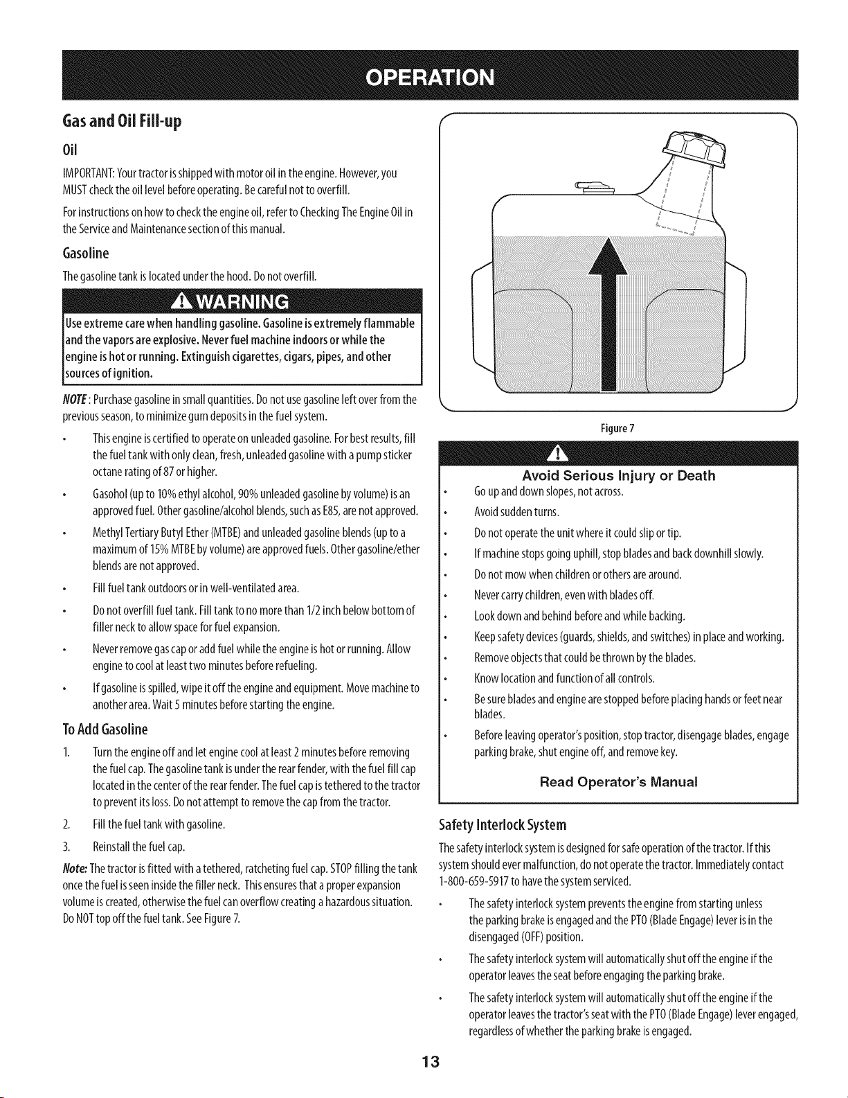
ToAdd Gasoline
1. Turnthe engineoff andletenginecoolat least2minutesbeforeremoving
thefuelcap.Thegasolinetankisunderthe rearfender,with thefuel fill cap
locatedin thecenterofthe rearfender.Thefuel capistetheredto the tractor
to preventits loss.Donotattempt to removethecapfrom the tractor.
2. Fillthefuel tank withgasoline.
3. Reinstallthe fuel cap.
Note:Thetractorisfitted with atethered,ratchetingfuel cap.STOPfilling thetank
oncethe fuel isseeninsidethe filler neck.Thisensuresthataproperexpansion
volumeiscreated,otherwisethefuel canoverflowcreatinga hazardoussituation.
DoNOTtop offthe fueltank.SeeFigure7.
Figure7
Avoid Serious Injury or Death
Goupanddownslopes,notacross.
Avoidsuddenturns.
Donotoperatetheunitwhereit couldslipor tip.
If machinestopsgoinguphill,stopbladesandbackdownhillslowly.
Donotmowwhenchildrenor othersarearound.
Nevercarrychildren,evenwith bladesoff.
Lookdown andbehindbeforeandwhilebacking.
Keepsafetydevices(guards,shields,andswitches)inplaceandworking.
Removeobjectsthat couldbethrown bytheblades.
Knowlocationandfunctionof all controls.
Besurebladesandenginearestoppedbeforeplacinghandsor feet near
blades.
Beforeleavingoperator'sposition,stoptractor,disengageblades,engage
parkingbrake,shutengineoff,andremovekey.
Read Operator's Manual
Safety Interlock System
Thesafetyinterlocksystemisdesignedfor safeoperationofthe tractor.Ifthis
systemshouldevermalfunction,do notoperatethetractor.Immediatelycontact
1-800-659-5917to havethesystemserviced.
Thesafetyinterlocksystempreventstheenginefrom startingunless
theparkingbrakeisengagedandthePTO(BladeEngage)leverisin the
disengaged(OFF)position.
Thesafetyinterlocksystemwill automaticallyshutoff the engineif the
operatorleavesthe seatbeforeengagingthe parkingbrake.
Thesafetyinterlocksystemwill automaticallyshutoff the engineif the
operatorleavesthe tractor'sseatwiththe PTO(BladeEngage)leverengaged,
regardlessofwhetherthe parkingbrakeisengaged.
13
Theenginewill automaticallyshut off if thePTO(BladeEngage)leveris
movedintothe engaged(ON)positionwith theshift leverinReverse.
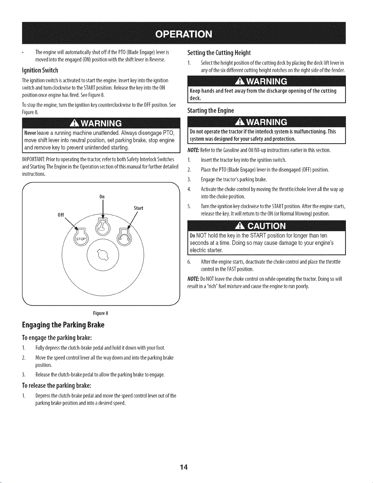
Ignition Switch
Theignitionswitchisactivatedto starttheengine.Insertkeyintothe ignition
switchandturn clockwiseto the STARTposition.Releasethe keyintothe ON
positiononceenginehasfired.SeeFigure8.
Tostoptheengine,turn the ignitionkeycounterclockwiseto theOFFposition.See
Figure8.
Neverleave a running machine unattended. Always disengage PTO,
move shift lever intoneutral position, set parking brake, stop engine
land remove key to prevent un ntended start ng.
IMPORTANT:Priorto operatingthe tractor,referto bothSafetyInterlockSwitches
andStartingTheEngineintheOperationsectionof thismanualforfurther detailed
instructions.
On
Off
Start
Setting the CuttingHeight
1. Selectthe heightpositionof thecuttingdeckbyplacingthedecklift leverin
anyof thesixdifferentcutting heightnotchesonthe rightsideof the fender.
Keephandsand feet away from the discharge opening of the cutting
deck.
Starting the Engine
Donot operatethe tractor if the interlock systemis malfunctioning. This
systemwasdesignedfor your safetyandprotection.
NOTE:Referto theGasolineand0ii fill-up instructionsearlierinthissection.
1. Insertthe tractorkeyintothe ignitionswitch.
2. PlacethePTO(BladeEngage)leverinthe disengaged(OFF)position.
3. Engagethe tractor'sparkingbrake.
4. Activatethe chokecontrolbymovingthethrottle/chokeleverall the wayup
intothechokeposition.
5. Turnthe ignitionkeyclockwiseto theSTARTposition.Afterthe enginestarts,
releasethekey.It will returnto theON(orNormalMowing)position.
DoNOTholdthe key in the STARTpositionfor longer thanten
secondsat atime. Doingso may causedamageto yourengine's
electricstarter.
6. Afterthe enginestarts,deactivatethechokecontrolandplacethethrottle
controlinthe FASTposition.
NOTE:DoNOTleavethechokecontrolonwhile operatingthe tractor.Doingsowill
resultina"rich"fuel mixtureandcausethe engineto run poorly.
J
Figure8
Engagingthe ParkingBrake
Toengage the parking brake:
I. Fullydepresstheclutch-brakepedalandholditdown withyourfoot.
2. Movethe speedcontrolleverall the waydownandinto theparkingbrake
position.
3. Releasethe clutch-brakepedalto allowtheparkingbraketo engage.
Toreleasethe parking brake:
I. Depressthe clutch-brakepedalandmovethe speedcontrolleveroutof the
parkingbrakepositionandinto adesiredspeed.
14
Stopping the Engine
If you strikea foreign object,stop theengine,disconnectthe sparkplug
wire(s) andground againstthe engine.Thoroughlyinspectthe machinefor
anydamage.Repairthe damagebeforerestarting and operating
1. If thebladesareengaged,placethe PTO(BladeEngage)leverinthe
disengaged(OFF)position.
2. Turnthe ignitionkeycounterclockwiseto theSTOPposition.
3. Removethekeyfrom the ignitionswitchto preventunintendedstarting.
Driving TheTractor
Avoidsuddenstarts,excessivespeedandsuddenstops.
Donot leavethe seatof the tractor without first placingthe PTO(Blade
Engage)leverinthe disengaged(OFF)position, depressingthe brakepedal
andengagingthe parking brake.If leavingthetractor unattended,also
turn the ignition keyoff andremovethe key.
Alwayslook down andbehind beforeandwhile backingup to avoid aback-
overaccident.
1. Depresstheclutch-brakepedalto releasethe parkingbrakeandthenlet the
pedalup.
2. Movethe throttle leverintothe FAST(rabbit)position.
3. Placethe shift leverineithertheFORWARDor REVERSEposition.
IMPORTANT: DoNOTusetheshift leverto changethedirectionof travelwhen
thetractorisinmotion.Alwaysusetheclutch-brakepedalto bringthe tractorto a
completestopbeforeshifting.
4. Releasethe parkingbrakebydepressingtheclutch-brakepedaland
positioningthespeedcontrolleverinthe desiredposition.
IMPORTANT: First-timeoperatorsshouldusespeedpositions1or2. Become
completelyfamiliarwith the tractor'soperationandcontrolsbeforeoperatingthe
tractorinhigherspeedpositions.
5. Releaseclutch-brakepedalslowlyto put unit into motion.
6. Thelawntractorisbroughtto astopbydepressingtheclutch-brakepedal.
NOTE:Whenoperating the unit initially, there will be little difference
between the highest two speeds until after the belts have seated
themselves into the pulleys during the break-in period.
Before leaving the operator's position for any reason, disengage the
blades, place the shift lever in neutral, engage the parking brake,
shut engine off and remove the key.
2. Engagethe parkingbrake.
3. Shutengineoff andremovethekey.Doingsowill minimizethepossibility
of havingyourlawn"browned"byhotexhaustfromyourtractor'srunning
engine.
Ifunit stallswith speedcontrolin highspeed,orif unit will notoperatewith speed
controlleverinalowspeedposition,proceedasfollows:
1. Placeshift leverinNEUTRAL
2. Restartengine.
3. Placespeedcontrolleverin highestspeedposition.
4. Releaseclutch-brakepedalfully.
5. Depressclutch-brakepedal.
6. Placespeedcontrolleverin desiredposition.
7. Placeshift leverineitherFORWARDor REVERSE,andfollow normaloperating
procedures.
Driving OnSlopes
Referto the SLOPEGAUGEin theSafetyInstructionssectionof the manualto help
determineslopeswhereyoumayoperatethistractorsafely.
Donot mow on inclineswith aslope in excessof 15degrees(a rise of
approximately 2-I12feet every10feet). Thetractor could overturnand
causeseriousinjury.
Mow upanddownslopes,NEVERacross.
Exerciseextremecautionwhenchangingdirectiononslopes.
Watchforholes,ruts,bumps,rocks,orotherhiddenobjects.Uneventerrain
couldoverturnthemachine.Tallgrasscanhide obstacles.
Avoidturnswhendrivingonaslope.Ifa turn mustbemade,turndownthe
slope.Turningupaslopegreatlyincreasesthechanceof a rollover.
Avoidstoppingwhendrivingupa slope.If it isnecessaryto stopwhile
drivingupa slope,start upsmoothlyandcarefullyto reducethepossibility
of flippingthetractoroverbackward.
Engagingthe Blades
Engagingthe PTO(BladeEngage)transferspowerto the cuttingdeckorother
(separatelyavailable)attachments.Toengagethe blades,proceedasfollows:
1. Movethe throttle/chokecontrolleverto the FAST(rabbit)position.
2. Graspthe PTO(BladeEngage)leverandpivotitall thewayforwardinto the
engaged(ON)position.
3. Keepthe throttle leverintheFAST(rabbit)positionforthemostefficientuse
of thecuttingdeckor other(separatelyavailable)attachments.
NOTE:Theenginewill automaticallyshutoff ifthe PTO(BladeEngage)leveris
movedintotheengaged(ON)positionwiththe shift leverin Reverse.
IMPORTANT: Whenstoppingthetractorforanyreasonwhileon agrass
surface,always:
1. Placethe shift leverin neutral.
15
Mulching
Amulchkit isavailableasanattachment.Mulchingisa processof redrculating
grassclippingsrepeatedlybeneaththe cuttingdeck.Theultra-fineclippingsare
thenforcedbackintothe lawnwherethey actasanaturalfertilizer.
Amulchkit canbepurchased.Seethe ReplacementParts&Attachmentssectionof
thismanualformoreinformation.
Usingthe DeckLift Lever
Toraisethe cuttingdeck,movethedecklift leverto the left,then placeit inthe
notchbestsuitedfor yourapplication.Referto SettingTheCuttingHeightearlierin
thisOperationsection.
MOWING
Tohelpavoidbladecontact orathrown objectinjury,keepbystanders,
[ helpers,childrenand petsat least 75feet from the machinewhile it isin
[ operation.Stopmachineifanyoneentersthe area.
Thefollowinginformationwill behelpfulwhen usingthe cuttingdeckwith your
tractor:
Planyourmowing pattern to avoiddischargeof materialstoward roads,
sidewalks,bystandersandthe like.Also,avoiddischargingmaterial against
awall or obstruction which maycausedischargedmaterialto ricochetback
toward the operator.
Headlights
ThelampsareONwheneverthetractor'sengineisrunning.
Thelampsturn OFFwhentheignitionkeyismovedto theSTOPposition.
Donotmowat highgroundspeed,especiallyif amulchkit orgrasscollector
isinstalled.
Forbestresultsit isrecommendedthat the first two lapsbecutwith the
dischargethrowntowardsthe center.Afterthe first two laps,reversethe
directionto throwthe dischargeto theoutsideforthe balanceofcutting.
Thiswill givea betterappearanceto the lawn.
Donotcutthe grasstooshort.Shortgrassinvitesweedgrowthandyellows
quicklyindryweather.
Mowingshouldalwaysbedonewith theengineat full throttle.
Underheavierconditionsit maybe necessaryto go backoverthecut areaa
secondtimeto getacleancut.
DoNOTattemptto mowheavybrushandweedsandextremelytallgrass.
Yourtractorisdesignedto mowlawns,NOTclearbrush.
Keepthebladessharpandreplacethebladeswhenworn.Referto Cutting
BladesintheServicesectionof thismanualfor properbladesharpening
instructions.
16
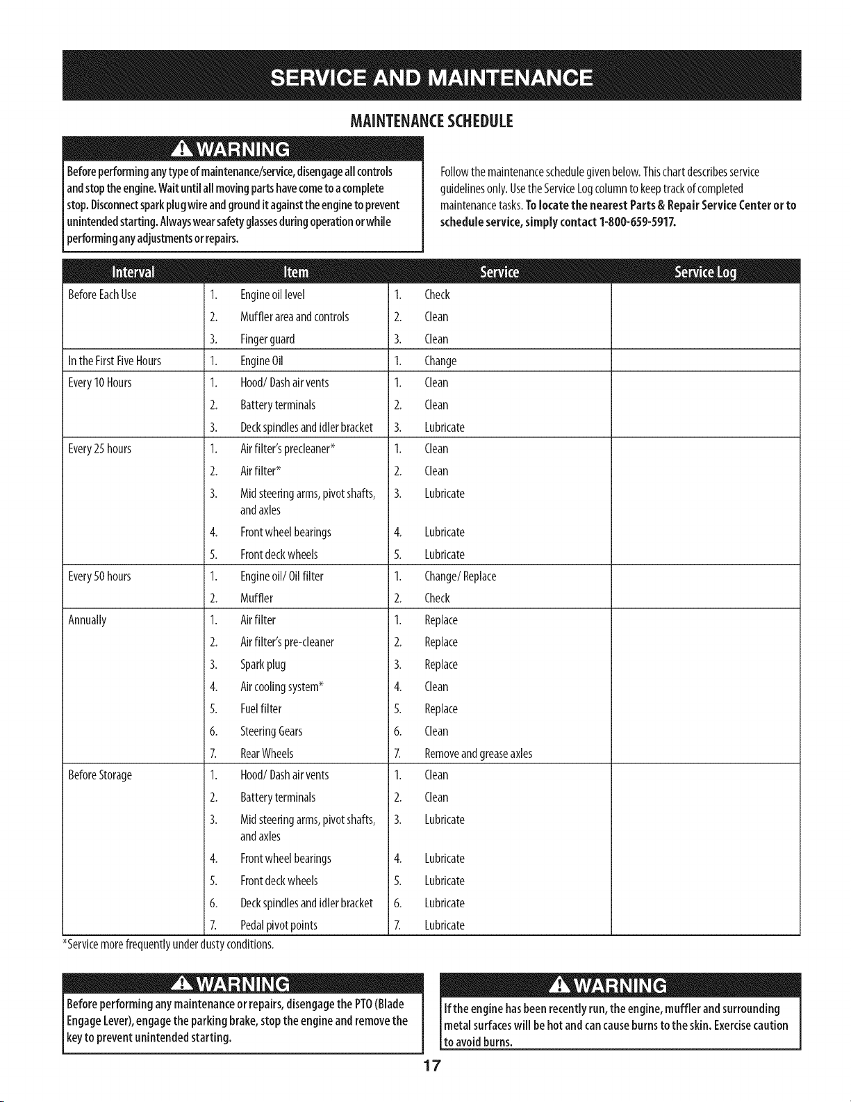
MAINTENANCESCHEDULE
Beforeperforminganytypeofmaintenance/service,disengageall controls
andstoptheengine.Waituntil allmovingpartshavecometo acomplete
stop.Disconnectsparkplugwire andgroundit againstthe engineto prevent
unintendedstarting.Alwayswearsafetyglassesduringoperationor whUe
performinganyadjustmentsor repairs.
BeforeEachUse I. Engineoil level I.
2. Mufflerareaandcontrols 2.
3. Fingerguard 3.
Inthe FirstFiveHours I. EngineOil I.
Every10Hours I. Hood/Dashair vents I.
2. Batteryterminals 2.
3. Deckspindlesandidlerbracket 3.
Every25hours 1. Airfilter'sprecleaner* 1.
2. Airfilter* 2.
3. Midsteeringarms,pivotshafts, 3.
andaxles
4. Frontwheelbearings 4.
5. Frontdeckwheels 5.
Every50hours 1. Engineoil/Oil filter 1.
2. Muffler 2.
Annually 1. Airfilter 1.
2. Airfilter'spre-cleaner 2.
3. Sparkplug 3.
4. Aircoolingsystem* 4.
5. Fuelfilter 5.
6. SteeringGears 6.
7. RearWheels 7.
BeforeStorage 1. Hood/Dashair vents 1.
2. Batteryterminals 2.
3. Midsteeringarms,pivotshafts, 3.
andaxles
4. Frontwheelbearings
5. Frontdeckwheels
6. Deckspindlesandidlerbracket
7. Pedalpivotpoints
*Servicemorefrequentlyunderdustyconditions.
Followthe maintenanceschedulegivenbelow.Thischartdescribesservice
guidelinesonly.Usethe ServiceLogcolumnto keeptrackofcompleted
maintenancetasks.Tolocate the nearest Parts & RepairServiceCenter or to
scheduleservice,simply contact 1-800-659-5917.
Check
Clean
Clean
Change
Clean
Clean
Lubricate
Clean
Clean
Lubricate
Lubricate
Lubricate
Change/Replace
Check
Replace
Replace
Replace
Clean
Replace
Clean
Removeandgreaseaxles
Clean
Clean
Lubricate
4. Lubricate
5. Lubricate
6. Lubricate
7. Lubricate
Beforeperformingany maintenanceor repairs,disengagethe PTO(Blade
EngageLever),engagethe parking brake,stopthe engineandremovethe
keyto prevent unintendedstarting.
If the enginehasbeen recentlyrun,the engine,muffler andsurrounding
metal surfaceswill behot andcancauseburnsto the skin. Exercisecaution
to avoidburns.
17
Engine Maintenance
Checkingthe EngineOil
Onlyusehighqualitydetergentoil ratedwith APIserviceclassificationSF,SG,
SH,or SJ.Selecttheoil'sSAEviscositygradeaccordingto the expectedoperating
temperature.Followthechartbelow.Althoughmulti-viscosityoils (5W20,10W30,
etc.)improvestartingin coldweather,theywill resultinincreasedoil consumption
whenusedabove32°1:.Checkyourengineoil levelmorefrequentlyto avoidpossible
enginedamagefrom runninglowon oil.
E
Colder _ 32°F _Warmer
1.
2.
3.
Oil Viscosity Chart
Tochecktheengineoil,proceedasfollows:
Ensurethat thetractorison alevelsurface.
Cleanthe oil fill areaof anydebris.
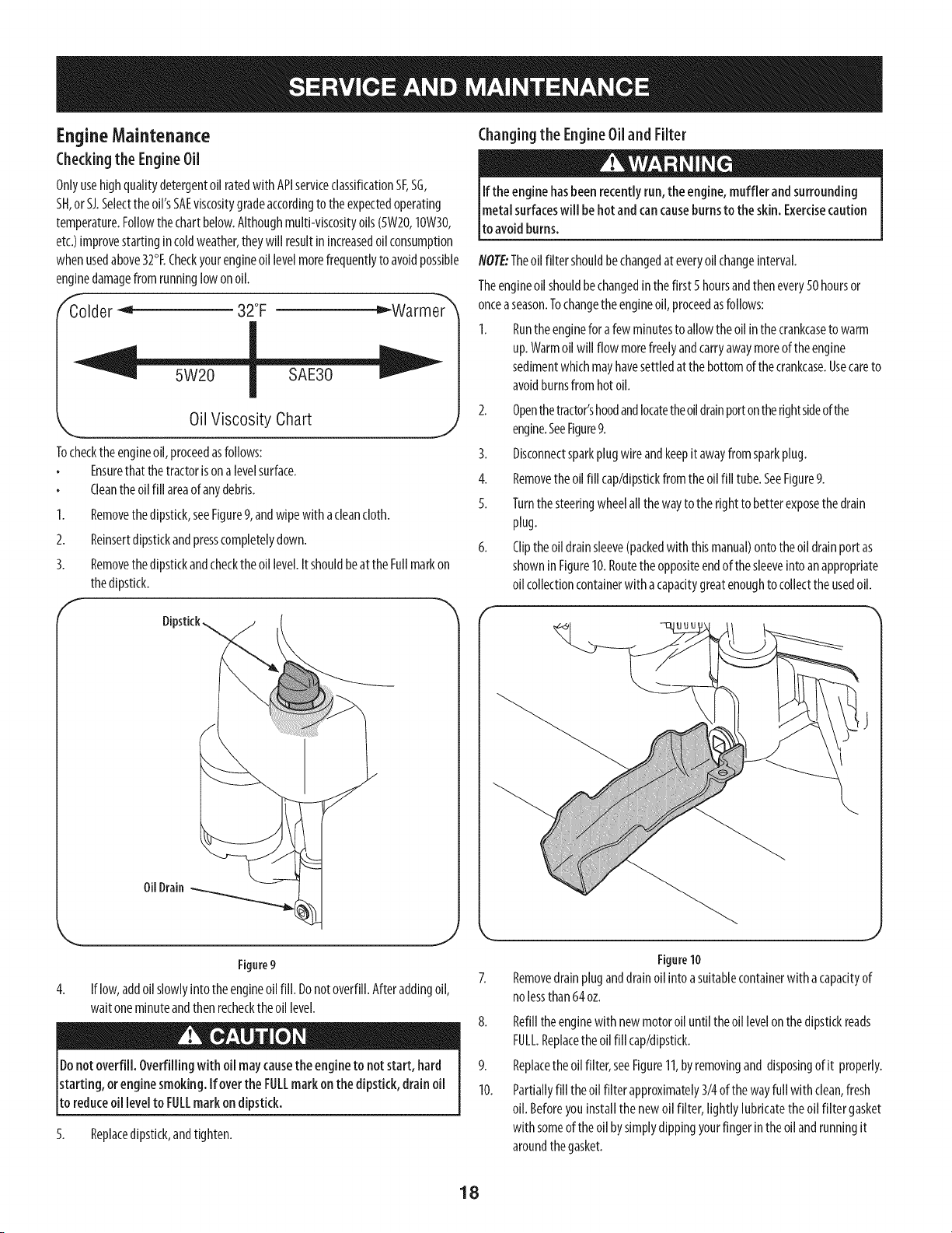
Removethe dipstick,seeFigure9,andwipewith acleancloth.
Reinsertdipstickandpresscompletelydown.
F
J
Removethe dipstickandchecktheoil level.Itshouldbeat the Fullmarkon
thedipstick.
Dipstick
OilDrain
Changingthe EngineOiland Filter
If the enginehasbeenrecentlyrun, the engine,muffler andsurrounding
metal surfaceswill be hot and cancauseburns to the skin. Exercisecaution
to avoidburns.
NOTE:Theoil filter shouldbechangedat everyoil changeinterval.
Theengineoil shouldbechangedin the first 5hoursandthenevery50 hoursor
onceaseason.Tochangethe engineoil,proceedasfollows:
1. Runtheengineforafew minutesto allowtheoil inthe crankcaseto warm
up.Warmoil will flow morefreelyandcarryawaymoreof the engine
sedimentwhichmayhavesettledatthe bottomof thecrankcase.Usecareto
avoidburnsfrom hot oil.
2. Openthetractor'shoodandlocatetheoil drainportontherightsideof the
engine.SeeFigure9.
3. Disconnectsparkplug wireandkeepit awayfromsparkplug.
4. Removetheoil fill cap/dipstkkfromtheoil fill tube.SeeFigure9.
5. Turnthe steeringwheelall thewayto the rightto betterexposethe drain
plug.
6. Cliptheoil drainsleeve(packedwith thismanual)ontotheoil drainport as
showninFigure10.Routetheoppositeendof the sleeveinto anappropriate
oil collectioncontainerwith acapacitygreatenoughto collectthe usedoil.
Figure9
4. If low,addoii slowlyinto theengineoii fill. Donotoverfill.Afteraddingoii,
waitoneminuteandthenrecheckthe oil level.
Donotoverfill. Overfilling withoii maycausethe engineto not start, hard
starting, orengine smoking. If overthe FULLmark onthedipstick, drain oil
to reduceoil levelto FULLmark on dipstick.
5. Replacedipstick,andtighten.
Figure10
Removedrainpluganddrainoil intoasuitablecontainerwith a capacityof
nolessthan64oz.
8. Refilltheenginewith newmotoroil untilthe oil levelonthe dipstickreads
FULL.Replacethe oil fill cap/dipstick.
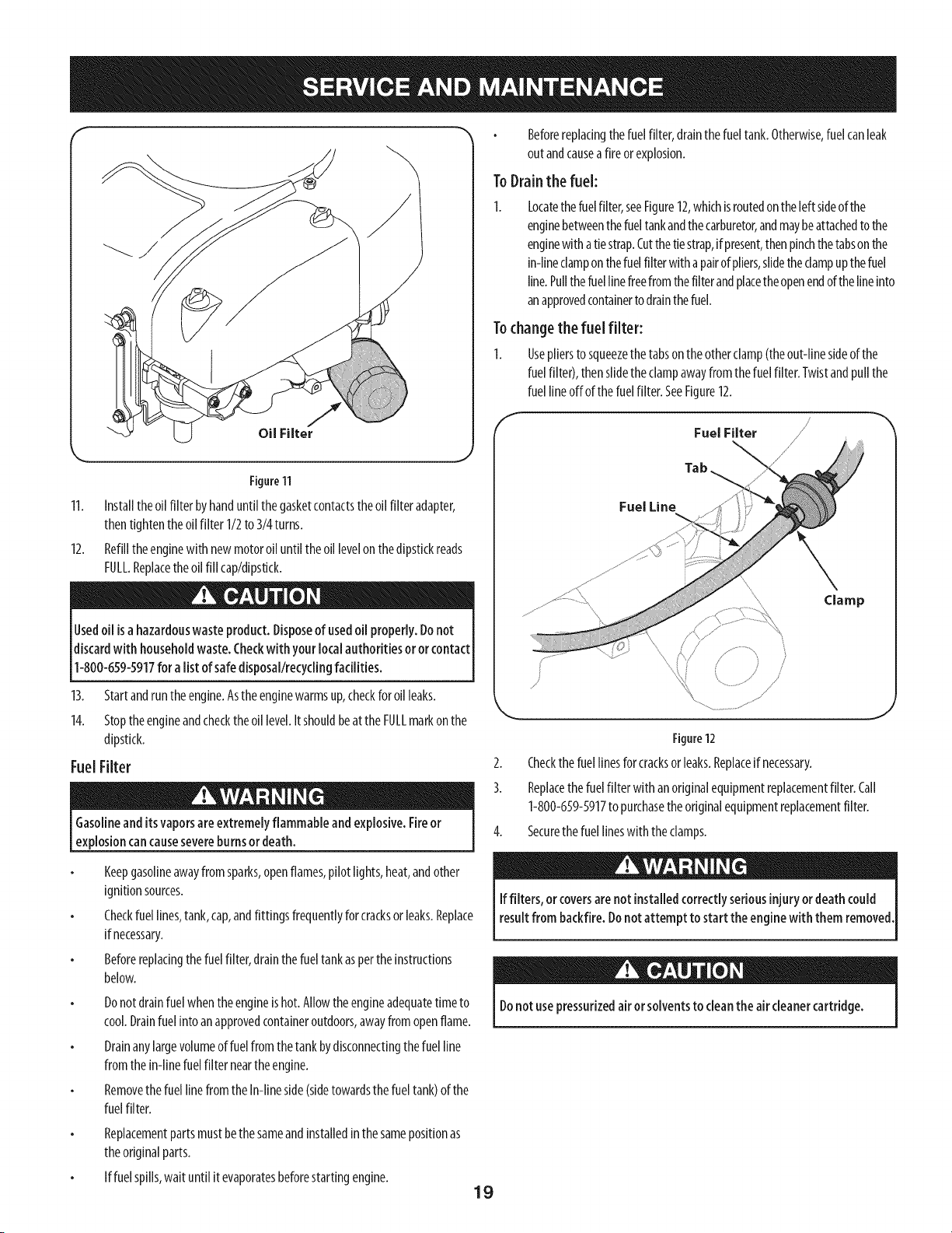
9. Replacethe oil filter,seeFigure11,byremovingand disposingof it properly.
10. Partiallyfill theoil filterapproximately3/4of the wayfull with clean,fresh
oil. Beforeyou installthenewoil filter, lightly lubricatetheoil filter gasket
with someof theoil bysimplydippingyourfinger in theoil andrunningit
aroundthe gasket.
18
f
Oil Filter
Figure11
11. Installtheoil filter byhanduntil thegasketcontactstheoil filter adapter,
thentightentheoil filter 1/2to 3/4turns.
12. Refilltheenginewith newmotoroiluntil the oil levelon thedipstickreads
FULL.Replacetheoil fill cap/dipstkk.
Usedoil isahazardouswaste product. Disposeof usedoil properly.Donot
discardwith householdwaste.Checkwith your local authorities or orcontact
1-800-659-5917for a list of safedisposal/recyclingfacilities.
13. Startandruntheengine.Astheenginewarmsup,checkforoil leaks.
14. Stopthe engineandchecktheoil level.It shouldbeat the FULLmarkonthe
dipstick.
Fuel Filter
Gasolineanditsvaporsare extremelyflammable andexplosive.Fireor
explosioncan causesevereburns ordeath.
Keepgasolineawayfrom sparks,openflames,pilot lights,heat,andother
ignitionsources.
Checkfuellines,tank,cap,andfittingsfrequentlyforcracksor leaks.Replace
if necessary.
Beforereplacingthefuelfilter, drainthefuel tankasperthe instructions
below.
Donotdrainfuel whentheengineishot.Allowtheengineadequatetimeto
cool.Drainfuel into anapprovedcontaineroutdoors,awayfromopenflame.
Drainanylargevolumeoffuel fromthetankbydisconnectingthe fuel line
fromthe in-linefuel filter neartheengine.
Removethe fuel linefromthe In-lineside(sidetowardsthe fuel tank)of the
fuelfilter.
Replacementpartsmustbethesameandinstalledinthe samepositionas
theoriginalparts.
If fuelspills,wait until it evaporatesbeforestartingengine.
Beforereplacingthefuel filter,drainthefuel tank.Otherwise,fuel canleak
outandcauseafire orexplosion.
ToDrainthe fuel:
Locatethefuelfilter,seeFigure12,whichisroutedon theleft sideofthe
enginebetweenthefueltankandthecarburetor,andmaybeattachedto the
enginewithatie strap.Cutthetiestrap,if present,thenpinchthetabsonthe
in-lineclamponthefuel filter withapairof pliers,slidethe clampupthefuel
line.Pullthe fuellinefreefrom thefilterandplacetheopenendof thelineinto
anapprovedcontainertodrainthefuel.
Tochangethe fuel filter:
1. Usepliersto squeezethe tabsontheotherclamp(theout-linesideof the
fuelfilter), thenslidetheclampawayfrom the fuelfilter. Twistandpullthe
fuel lineoffof the fuelfilter.SeeFigure12.
Fuel Filter
\
Tab
Fuel Line
j/
Figure12
2. Checkthe fuellinesforcracksorleaks.Replaceif necessary.
3. Replacethe fuel filter with an originalequipmentreplacementfilter. Call
1-800-659-5917to purchasethe originalequipmentreplacementfilter.
4. Securethefuel lineswith the clamps.
If filters, orcoversarenot installedcorrectlyseriousinjuryor death could
resultfrom backfire.Donot attempt to start the enginewith them removed,
Donot usepressurizedair or solventsto cleanthe air cleanercartridge.
19
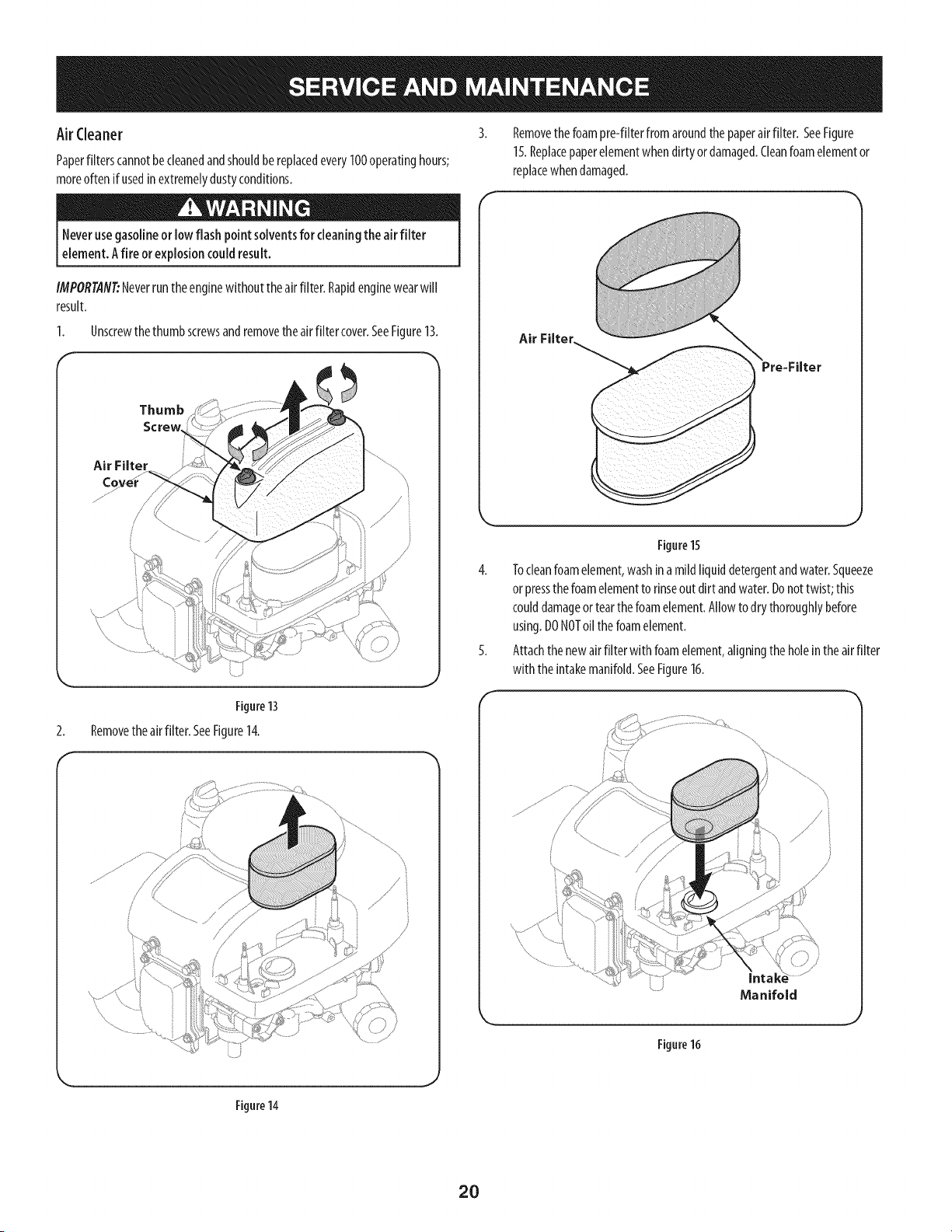
Air Cleaner
Paperfilterscannotbecleanedandshouldbe replacedevery100operatinghours;
moreoftenif usedin extremelydustyconditions.
Removethe foampre-fiIterfrom aroundthe paperairfilter. SeeFigure
15.Replacepaperelementwhen dirtyor damaged.Cleanfoamelementor
replacewhendamaged.
Neverusegasolineor lowflash point solventsfor cleaningtheair filter
element.Afire orexplosioncould result.
IMPORTANT:Neverruntheenginewithout theairfilter. Rapidenginewearwill
result.
1. Unscrewthethumbscrewsandremovetheairfilter cover.SeeFigure13.
Thumb
Screw
Air FHter
//
2.
Figure13
Removethe airfilter. SeeFigure14.
Figure 14
Air FHter
Figure15
4. Tocleanfoamelement,washina mildliquiddetergentandwater.Squeeze
orpressthe foamelementto rinseout dirt andwater.Donottwist;this
coulddamageortearthefoamelement.Allowto dry thoroughlybefore
using.DONOToil thefoamelement.
5. Attachthe newair filter with foamelement,aligningthe holeintheairfilter
with the intakemanifold.SeeFigure16.
/
/
Manifold
Figure16
20
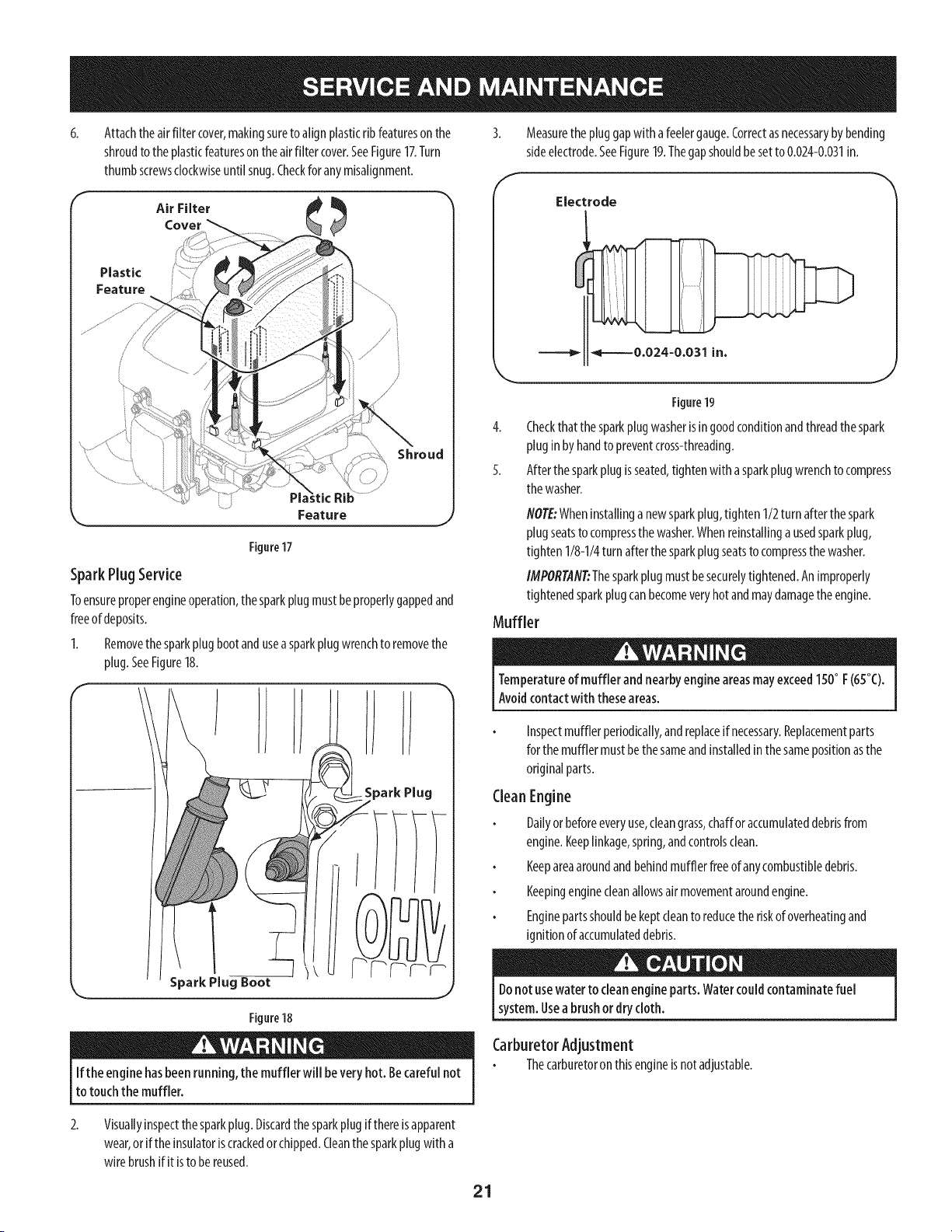
6.
Attachtheairfilter cover,makingsureto alignplasticrib featuresonthe
shroudto theplasticfeatureson the airfilter cover.SeeFigure17.Turn
thumbscrewsclockwiseuntilsnug.Checkfor anymisalignment.
Air Filter
Cover
Plastic
Feature
Shroud
Feature
Figure17
SparePlug Service
Toensureproperengineoperation,thesparkplugmustbeproperlygappedand
freeofdeposits.
1. Removethesparkplugbootandusea sparkplugwrenchto removethe
plug.SeeFigure18.
f
Spark Plug
J
If the enginehasbeenrunning, the muffler will beveryhot. Becareful not
to touch the muffler.
Measurethe pluggapwith afeelergauge.Correctasnecessarybybending
sideelectrode.SeeFigure19.Thegapshouldbesetto 0.024-0.031in.
Electrode
_=--_0.024-0.031 in,
J
Figure19
4. Checkthatthe sparkplugwasherisingoodconditionandthreadthespark
pluginby handto preventcross-threading.
5. Afterthe sparkplugis seated,tightenwith asparkplugwrenchto compress
thewasher.
NOTE:Wheninstallinga newsparkplug,tighten1/2turnafter thespark
plugseatsto compressthewasher.Whenreinstallinga usedsparkplug,
tighten1/8-1/4turn afterthesparkplugseatsto compressthewasher.
IMPORTANT:Thesparkplugmustbesecurelytightened.Animproperly
tightenedsparkplugcanbecomeveryhotandmaydamagethe engine.
Muffler
Temperatureof muffler and nearbyengine areasmayexceed150° F(65°C).
Avoidcontactwith theseareas.
Inspectmufflerperiodically,andreplaceif necessary.Replacementparts
forthe mufflermustbethe sameandinstalledin thesamepositionasthe
originalparts.
CleanEngine
Dailyor beforeeveryuse,cleangrass,chafforaccumulateddebrisfrom
engine.Keeplinkage,spring,andcontrolsclean.
Keepareaaroundandbehindmufflerfreeofanycombustibledebris.
Keepingenginecleanallowsair movementaroundengine.
Enginepartsshouldbe keptcleanto reducetheriskof overheatingand
ignitionof accumulateddebris.
Donot usewater to cleanengineparts. Watercouldcontaminatefuel
system.Usea brushor drycloth.
CarburetorAdjustment
Thecarburetoronthisengineisnotadjustable.
2.
Visuallyinspectthe sparkplug.Discardthe sparkplugif thereisapparent
wear,orif theinsulatoriscrackedorchipped.Cleanthe sparkplugwith a
wirebrushif it isto be reused.
21
Lubrication
Beforelubricating,repairing,or inspecting,alwaysdisengagePTO(Blade
EngageLever),moveshift leverintoneutral position, set parking brake,stop
eng ne andremovekeyto prevent un ntendedstart rig.
Pivot Points& Linkage
Lubricateall the pivot pointsonthedrivesystem,parkingbrakeandlift linkageat
leastonceaseasonwith light oil.
RearWheels
Therearwheelsshouldberemovedfromtheaxlesonceaseason.Lubricatethe
axlesandtherimswell with anall-purposegreasebeforere-installingthem.
Front Axles
Eachendof thetractor'sfront pivotbarmaybeequippedwith agreasefitting.
Lubricatewith agreasegunafterevery25 hoursof tractoroperation.
Battery
Thebatteryissealedandis maintenance-free.Acidlevelscannotbechecked.
Alwayskeepthe batterycablesandterminalscleanandfreeofcorrosive
build-up.
Aftercleaningthe batteryandterminals,applya lightcoatof petroleumjelly
orgreaseto bothterminals.
Alwayskeepthe rubberbootpositionedoverthe positiveterminalto prevent
shorting.
IM PORTANT: If removingthe batteryforanyreason,disconnectthe NEGATIVE
(Black)wirefrom its terminalfirst, followedbythePOSITIVE(Red)wire.When
re-installingthe battery,alwaysconnectthe POSITIVE(Red)wireto its terminal
first,followedbytheNEGATIVE(Black)wire. Becertainthatthe wiresareconnected
to thecorrectterminals;reversingthemcouldchangethe polarityandresultin
damageto yourengine'salternatingsystem.
CleaningBattery
Cleanthe batterybyremovingit fromthe tractorandwashingwith a bakingsoda
andwatersolution.Ifnecessary,scrapethebatteryterminalswitha wirebrushto
removedeposits.Coatterminalsandexposedwiring with greaseorpetroleumjelly
to preventcorrosion.
Battery Failures
Somecommoncausesforbatteryfailureare:
Incorrectinitialactivation
Overcharging
Freezing
Undercharging
Corrodedconnections
ThesefailuresareNOTcoveredbyyourtractor'swarranty.
Cleaning the EngineAnd Deck
Anyfuel oroil spilledonthemachineshouldbewipedoff promptly.DoNOTallow
debristo accumulatearoundthecoolingfinsof theengineoronanyotherpart of
themachine.
IMPORTANT: Theuseofa pressurewasherto cleanyourtractorisNOT
recommended.It maycausedamageto electricalcomponents,spindles,pulleys,
bearingsortheengine.
Adjustments
Neverattempt to makeanyadjustmentswhile the engine isrunning,except
where specifiedintheoperator'smanual.
Levelingthe Deck
NOTE:Checkthetractor'stirepressurebeforeperforminganydeckleveling
adjustments.RefertoTiresintheServicesectionofthismanualformore
informationregardingtirepressure.
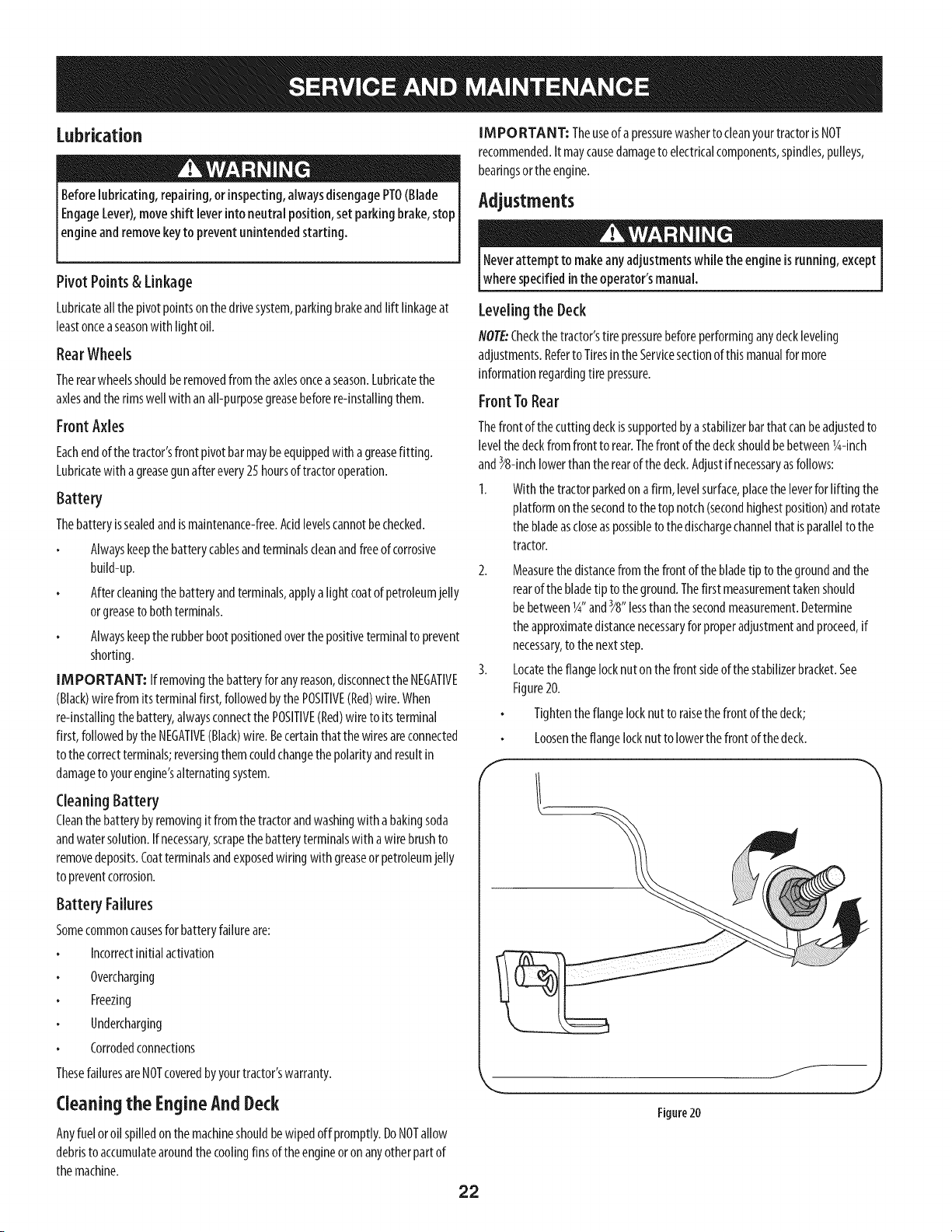
FrontTo Rear
Thefront of the cuttingdeckissupportedbyastabilizerbarthat canbeadjustedto
levelthedeckfrom front to rear.Thefront of thedeckshouldbebetween1g-inch
and_8-inchlowerthantherearofthe deck.Adjustif necessaryasfollows:
1. With the tractorparkedon afirm, levelsurface,placetheleverfor lifting the
platformon the secondto thetop notch(secondhighestposition)androtate
the bladeascloseaspossibleto thedischargechannelthatisparallelto the
tractor.
2. Measurethedistancefromthefront of thebladetip to thegroundandthe
rearof thebladetip to theground.Thefirst measurementtakenshould
bebetweenlg" and_8" lessthanthesecondmeasurement.Determine
theapproximatedistancenecessaryforproperadjustmentandproceed,if
necessary,to the nextstep.
3. Locatetheflangelocknutonthe front sideof thestabilizerbracket.See
Figure20.
Tightentheflangelocknutto raisethe front of thedeck;
Loosentheflangelocknutto lowerthefront of thedeck.
f
J
22
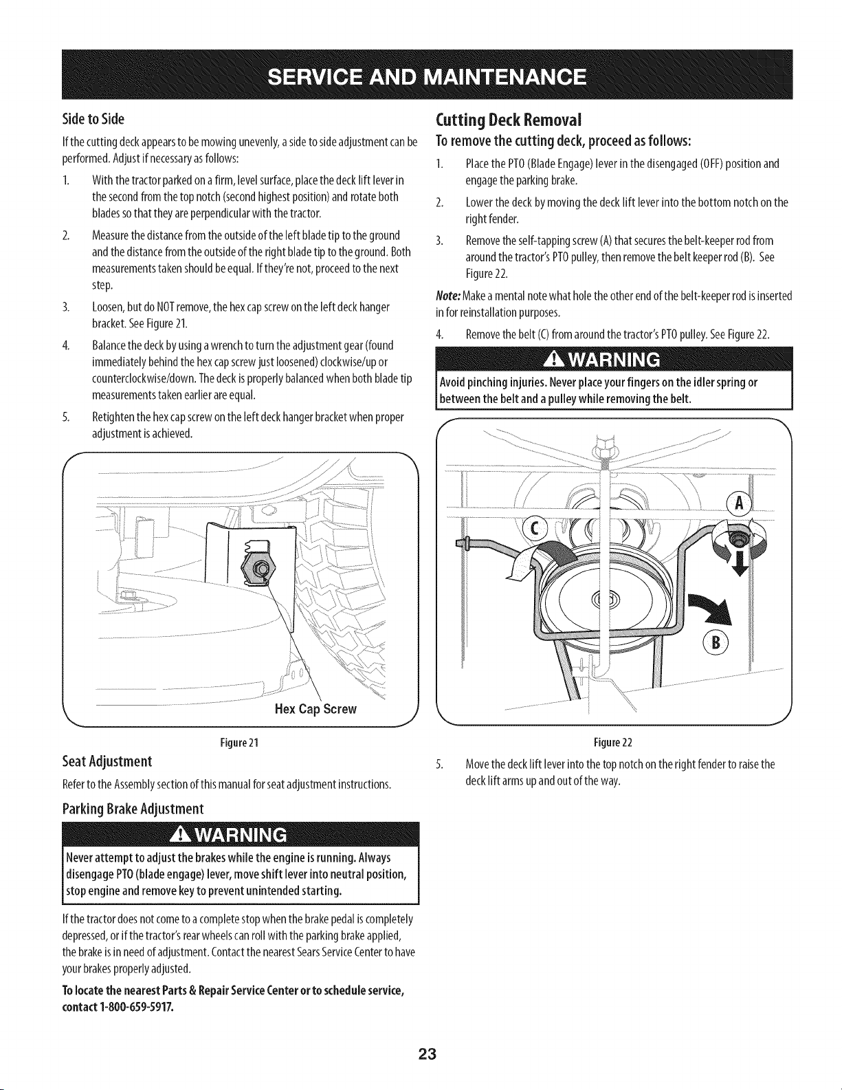
Sideto Side
If the cuttingdeckappearsto bemowingunevenly,asideto sideadjustmentcanbe
performed.Adjustif necessaryasfollows:
1. With thetractorparkedona firm, levelsurface,placethedecklift leverin
thesecondfrom thetop notch(secondhighestposition)androtateboth
bladessothattheyareperpendicularwith thetractor.
2. Measurethedistancefrom the outsideof the left bladetip to theground
andthe distancefromthe outsideoftheright bladetip to theground.Both
measurementstakenshouldbeequal.If they'renot,proceedto thenext
step.
3. Loosen,butdo NOTremove,the hexcapscrewon theleft deckhanger
bracket.SeeFigure21.
4. Balancethe deckby usingawrenchto turntheadjustmentgear(found
immediatelybehindthe hexcapscrewjust loosened)clockwise/upor
counterclockwise/down.Thedeckisproperlybalancedwhenbothbladetip
measurementstakenearlierareequal.
5. Retightenthe hexcapscrewontheleft deckhangerbracketwhen proper
adjustmentisachieved.
Hex Cap Screw
Figure21
SeatAdjustment
Referto theAssemblysectionofthis manualforseatadjustmentinstructions.
Parking BrakeAdjustment
Neverattempt to adjust the brakeswhile theengine isrunning. Always
disengagePTO(bladeengage)lever,moveshift leverinto neutral position,
stopengine andremovekeyto prevent unintendedstarting.
Cutting Deck Removal
To removethe cutting deck,proceed asfollows:
1. PlacethePTO(BladeEngage)leverin thedisengaged(OFF)positionand
engagethe parkingbrake.
2. Lowerthedeckbymovingthe decklift leverinto the bottom notchon the
right fender.
3. Removetheself-tappingscrewCA)that securesthebelt-keeperrodfrom
aroundthe tractor'sPTOpulley,thenremovethe belt keeperrod(B). See
Figure22.
Note:Makea mentalnotewhatholetheotherendofthe belt-keeperrodisinserted
inforreinstallationpurposes.
4. Removethebelt (C)fromaroundthetractor'sPTOpulley.SeeFigure22.
Avoid pinching injuries.Neverplaceyourfingers on the idler springor
between the beltand apulley while removingthe belt.
f
\
J
Figure22
Movethe decklift leverinto thetopnotchonthe right fenderto raisethe
decklift armsupandout oftheway.
If the tractordoesnotcometoa completestopwhenthe brakepedaliscompletely
depressed,or if thetractor'srearwheelscanrollwith theparkingbrakeapplied,
thebrakeisin needofadjustment.ContactthenearestSearsServiceCenterto have
yourbrakesproperlyadjusted.
Tolocate the nearest Parts& RepairService(:enter or to scheduleservice,
contact 1-800-659-5917.
23
/_
//
/
/
/
PTOCable
6.
Figure23
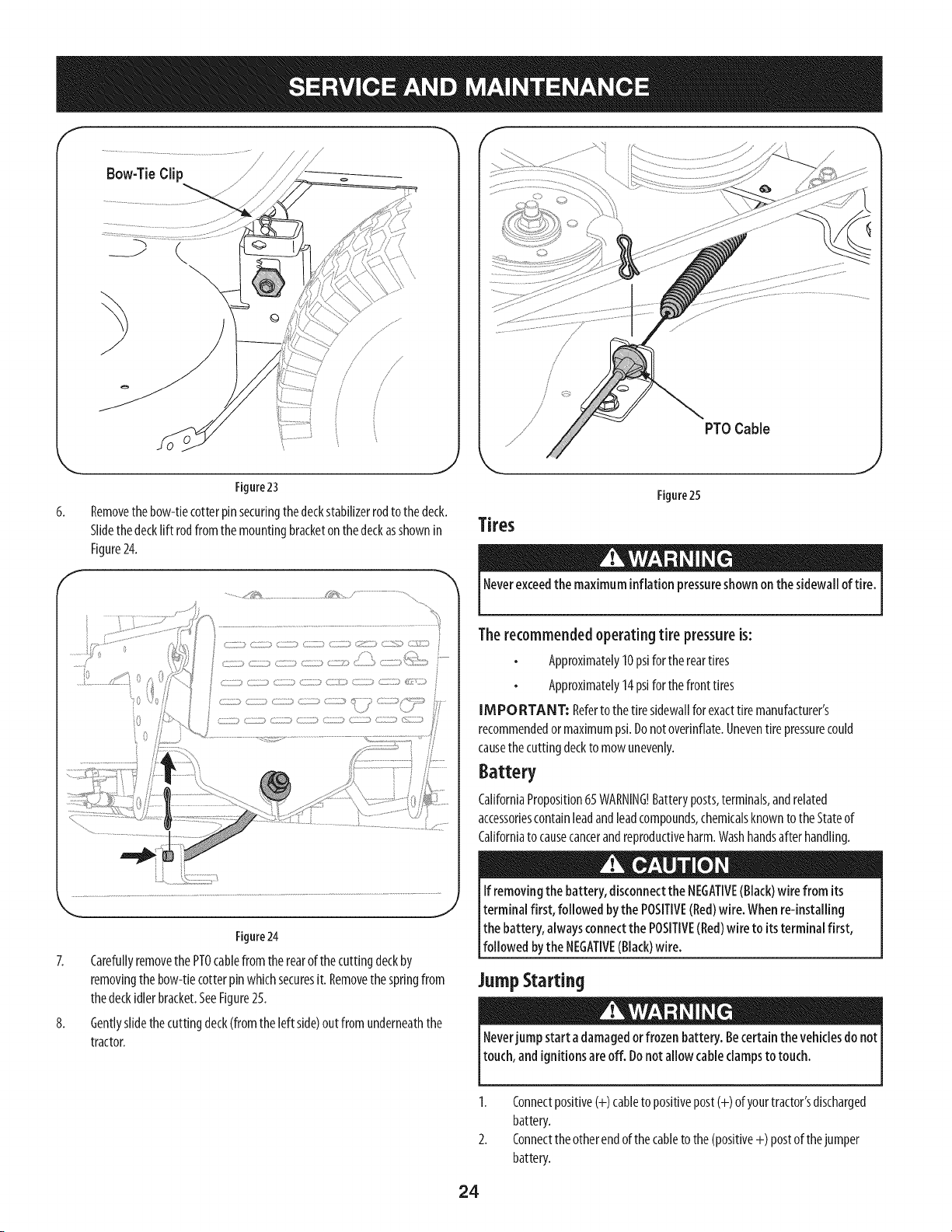
Removethe bow-tiecotterpin securingthedeckstabilizerrodto the deck.
Slidethe decklift rodfromthe mountingbracketon thedeckasshownin
Figure24.
f
,,__ /,__ ,........................
,.. j
Figure24
7. Carefullyremovethe PTOcablefrom the rearofthecuttingdeckby
removingthebow-tiecotterpinwhichsecuresit. Removethespringfrom
thedeckidlerbracket.SeeFigure25.
8. Gentlyslidethecuttingdeck(fromthe left side)out from underneaththe
tractor.
Tires
Figure25
Neverexceedthe maximuminflationpressureshownon thesidewall of tire.
The recommended operating tire pressure is:
Approximately10psiforthereartires
Approximately14psiforthefront tires
IMPORTANT: Referto thetire sidewallforexacttire manufacturer's
recommendedor maximumpsi.Donotoverinflate.Uneventirepressurecould
causethecuttingdeckto mow unevenly.
Battery
CaliforniaProposition65WARNING!Batteryposts,terminals,andrelated
accessoriescontainleadandleadcompounds,chemicalsknownto theStateof
Californiato causecancerandreproductiveharm.Washhandsafter handling.
If removingthe battery, disconnectthe NEGATIVE(Black)wire from its
terminal first, followed bythe POSITIVE(Red)wire. When re-installing
the battery, alwaysconnectthe POSITIVE(Red)wire to itsterminal first,
followed bythe NEGATIVE(Black)wire.
JumpStarting
Neverjumpstart adamagedorfrozen battery. Becertain the vehiclesdo not
touch, andignitionsare off. Donotallow cable clampsto touch.
1. Connectpositive(+) cableto positivepost(+) of yourtractor'sdischarged
battery.
2. Connecttheotherendofthe cableto the (positive+) postof thejumper
battery.
24
3. Connectthesecondcable(negative-) to the otherpostofthejumper
battery.
4. Connecttheotherendof the negativecableto theengineblockof the
tractor,awayfrom the battery.Attachtoan unpaintedpartto assureagood
connection.
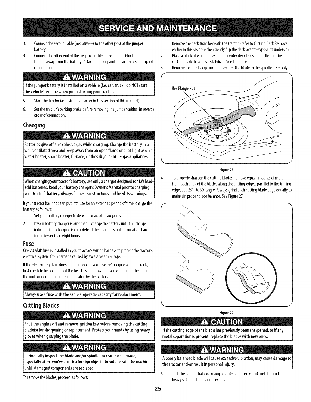
1. Removethedeckfrombeneaththetractor,(referto CuttingDeckRemoval
earlierinthissection)thengentlyflip the deckoverto exposeits underside.
2. Placeablockof woodbetweenthecenterdeckhousingbaffleandthe
cutting bladeto actasa stabilizer.SeeFigure26.
3. Removethehexflangenut that securesthebladeto thespindleassembly.
Ifthejumperbatteryisinstalledonavehicle(i.e.car,truck),doNOTstart
thevehicle'senginewhenjumpstartingyourtractor.
5. Startthetractor(asinstructedearlierin thissectionofthismanual).
6. Setthe tractor'sparkingbrakebeforeremovingthejumpercables,inreverse
orderof connection.
Charging
Batteriesgive off an explosivegaswhile charging.Chargethe battery ina
well ventilatedarea andkeepawayfrom anopenflame or pilotlight ason a
water heater,spaceheater,furnace,clothesdryeror other gasappliances.
HexFlangeNut
Whenchargingyourtractor'sbattery,useonlya chargerdesignedfor 12Vlead-
acidbatteries.Readyourbattery charger'sOwner'sManualpriorto charging
yourtractor'sbattery. Alwaysfollow itsinstructionsandheeditswarnings.
If yourtractorhasnotbeenput into usefor anextendedperiodof time,chargethe
batteryasfollows:
1. Setyourbatterychargerto deliveramaxof 10amperes.
2. If yourbatterychargerisautomatic,chargethebatteryuntil the charger
indicatesthatchargingiscomplete.Ifthechargeris notautomatic,charge
forno fewerthaneighthours.
Fuse
One20AMPfuseisinstalledin yourtractor'swiring harnessto protectthe tractor's
electricalsystemfrom damagecausedbyexcessiveamperage.
If the electricalsystemdoesnotfunction,oryourtractor'senginewill notcrank,
first checkto becertainthatthe fusehasnotblown.It canbefoundatthe rearof
theunit, underneaththefenderlocatedbythebattery.
Alwaysuseafuse with the sameamperagecapacityfor replacement.
Cutting Blades
Shutthe engineoffand removeignitionkeybeforeremovingthecutting
blade(s)for sharpeningor replacement.Protectyourhandsbyusingheavy
gloveswhengraspingthe blade.
Periodicallyinspectthe bladeand/or spindlefor cracksor damage,
especiallyafter you'vestruckaforeign object.Donot operatethe machine
until damagedcomponentsarereplaced.
Toremovetheblades,proceedasfollows:
Figure26
Toproperlysharpenthe cuttingblades,removeequalamountsofmetal
from bothendsof thebladesalongthecuttingedges,parallelto thetrailing
edge,at a25°- to 30°angle.Alwaysgrindeachcutting bladeedgeequallyto
maintainproperbladebalance.SeeFigure27.
\4
Figure27
If the cutting edgeof the bladehaspreviously beensharpened,or if any
metal separationis present,replacethe bladeswith new ones.
A poorlybalancedbladewill causeexcessivevibration,maycausedamageto
the tractor and/or result inpersonalinjury.
Testthe blade'sbalanceusinga bladebalancer.Grindmetalfromthe
heavysideuntil it balancesevenly.
25
NOTE:Whenreplacingtheblade,besureto installthebladewith thesideof the
blademarked"Bottom" (orwith a partnumberstampedin it) facingtheground
whenthemoweris intheoperatingposition.
Usea torque wrenchto tighten the bladespindle he×flange nutto between
70[bs-ft and90 [bs4t.
Changingthe DeckBelt
Besureto shut theengine off, removeignitionkey,disconnectthe spark
plugwire(s) andgroundagainstthe engine to preventunintended starting
[before removng the be t.
All belts on your tractor are subjectto wearand shouldbe replacedif any
signsof weararepresent.
IM PORTANT: TheV-beltfoundonyourtractorisspeciallydesignedto engage
anddisengagesafely.Asubstitute(non-OEM)V-beltcanbedangerousbynot
disengagingcompletely.Foraproperworkingmachine,useidenticalequipment
beltsaslistedinthe partspagesof thisOperator'sManual.
Tochangeor replacethe deckbelt onyourtractor,proceedasfollows:
Removethe deckasinstructedearlierinthissection.
4.
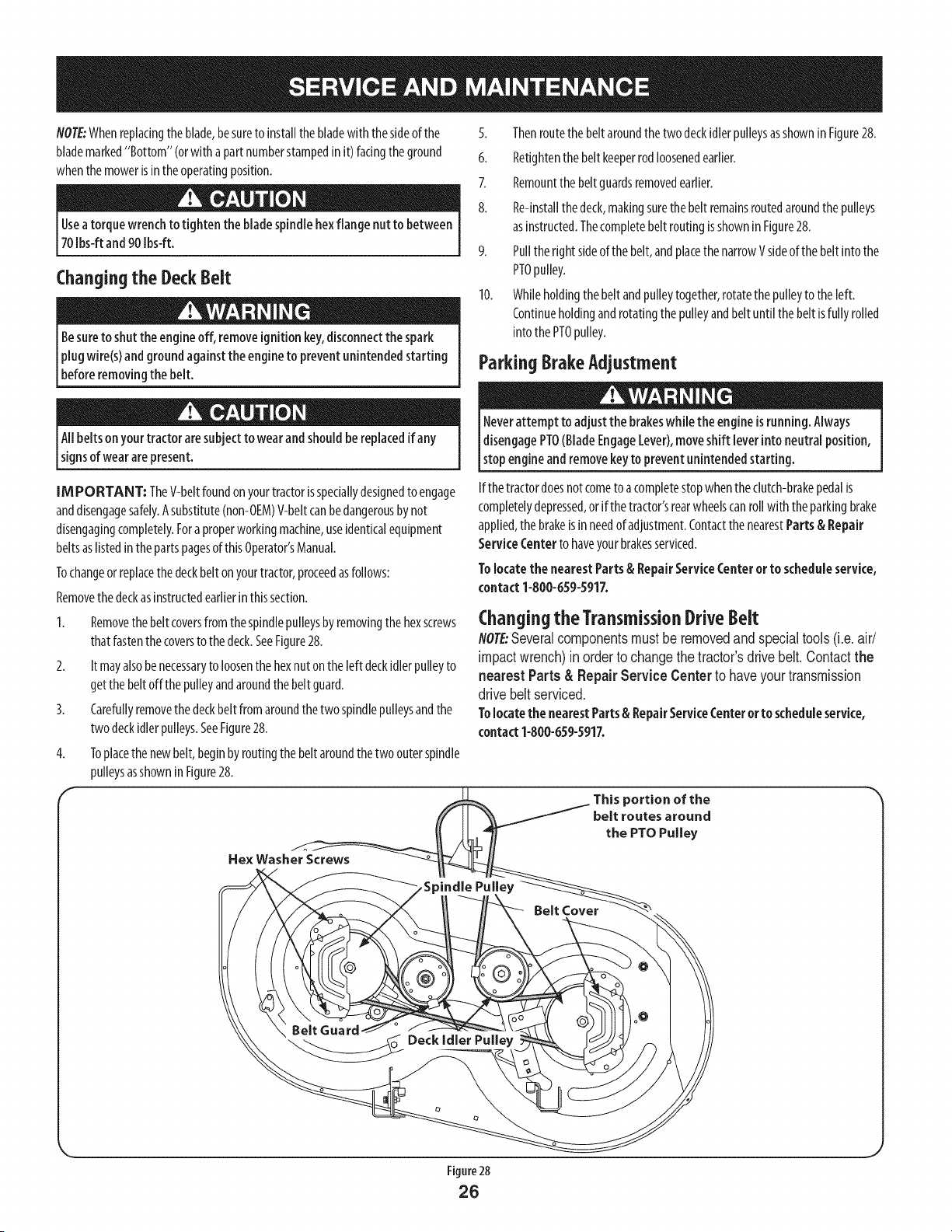
1. Removethebelt coversfromthespindlepulleysbyremovingthehexscrews
thatfastenthe coversto the deck.SeeFigure28.
2. It mayalsobenecessaryto loosenthehexnut onthe left deckidlerpulleyto
getthe beltoffthe pulleyandaroundthebelt guard.
3. Carefullyremovethe deckbeltfromaroundthetwo spindlepulleysandthe
two deckidlerpulleys.SeeFigure28.
Toplacethe newbelt,beginbyroutingthe beltaroundthetwo outerspindle
pulleysasshownin Figure28.
5. Thenroutethe beltaroundthetwodeckidlerpulleysasshownin Figure28.
6. Retightenthe beltkeeperrodloosenedearlier.
7. Remountthe beltguardsremovedearlier.
8. Re-installthedeck,makingsurethe belt remainsroutedaroundthe pulleys
asinstructed.Thecompletebelt routingisshownin Figure28.
9. Pullthe rightsideof thebelt,andplacethe narrowVsideof thebelt intothe
PTOpulley.
10. Whileholdingthebelt andpulleytogether,rotatethe pulleyto theleft.
Continueholdingandrotatingthepulleyandbelt until the belt isfully rolled
intothePTOpulley.
ParkingBrakeAdjustment
Neverattempt to adjustthe brakeswhile the engine isrunning.Always
[disengagePTO(BladeEngageLever),moveshift leverintoneutralposition,
[stop engineand removekeyto preventunintended starting.
Ifthe tractordoesnotcometo acompletestopwhentheclutch-brakepedalis
completelydepressed,or if thetractor'srearwheelscanroll with theparkingbrake
applied,thebrakeisin needofadjustment.ContactthenearestParts& Repair
ServiceCenterto haveyourbrakesserviced.
Tolocate the nearestParts& RepairServiceCenter orto scheduleservice,
contact1-800-659-5917.
Changing the TransmissionDriveBelt
NOTE"Several components must be removed and special tools (i.e. air/
impact wrench) in order to change the tractor's drive belt. Contact the
nearest Parts & Repair Service Center to have your transmission
drive belt serviced.
Tolocatethe nearestParts& RepairServiceCenteror to scheduleservice,
contact1-800-659-5917.
J
Neverstore lawn tractor with fuel in tank indoorsor inpoorly ventilated
areaswhere fuel fumes may reachan openflame, spark,or pilot light ason
afurnace,water heater,clothesdryer,or gasappliance.
PreparingTheEngine
IMPORTANT: Fuelleft inthefuel tankduringwarmweatherdeterioratesand
will causeseriousstartingproblems.
Topreventgumdepositsfromforminginsidethe engine'scarburetorandcausing
possiblemalfunctionofthe engine,thefuelsystemmustbeeithercompletely
emptied,orthe gasolinemustbetreatedwith astabilizerto preventdeterioration.
I. Ifusinga fuelstabilizer:
a. Readthe productmanufacturer'sinstructionsandrecommendations.
b. Addto clean,freshgasolinethecorrectamountofstabilizerforthe
capacityof thefuel system.
c. Fillthefueltankwith treatedfuel andrunthe enginefor 2-3minutesto
getstabilizedfuelinto thecarburetor.
2. Ifemptylngthefuelsystem:
a. Donotdrainfuelwhen theengineishot.Allowtheengineadequate
timeto cool.Drainfuel into anapprovedcontaineroutdoors,awayfrom
openflame.
b. Drainanylargevolumeof fuelfrom thetank bydisconnectingthe
fuel linefromthe in-linefuel filter nearthe engine.Seethe complete
instructionsforDrainingTheFuellaterin thissection.
Gasolineisextremely flammable and canbe explosiveundercertain
conditions. Draingasolinebeforestoring theequipment for extended
periods.Drainfuel only into anapprovedcontaineroutdoors,awayfrom
an open flame. Allow engine to cool.Extinguishcigarettes, cigars,pipes,
and othersourcesof ignition prior to draining fuel. Storegasolinein an
approvedcontainerin safe location.
c. Reconnectthefuel lineandrunthe engineuntil it startsto falter,then
usethe choketo keepthe enginerunninguntilall fuel in thecarburetor
hasbeenexhausted.
d. Disconnectthe fuel lineanddrainanyremaininggasolinefrom the
system.
DrainingThe Fuel
1. Locatethe fuel filter,whichis locatedonthe left sideoftheengine,andmay
be attachedto theenginewitha tiestrap.
2. Cutthetie strap,if present,thenpinchthe in-lineclamponthefuel filter
with a pairof pliers,slidethe clampupthefuel line.
3. Pullthefuellinefreefrom thefilter andplacethe openendofthe lineinto
an approvedcontainerto drainthefuel.
PreparingThelawn tractor
Cleanandlubricatetractorthoroughlyasdescribedinthelubrication
instructions.
2. Donot usea pressurewasheror gardenhoseto cleanyourunit.
3. Storemowerin adry,cleanarea.Donot storenextto corrosivematerials,
suchasfertilizer.
Gasolineisa toxicsubstance.Disposeof gasolineproperly. Contactyour
localauthorities for approveddisposalmethods.
3. Removethe sparkplugandpourone(1)ounceof engineoilthroughthespark
plugholeinto the cylinder.Crankthe engineseveraltimesto distributethe
oil. Replacethe sparkplug.
27
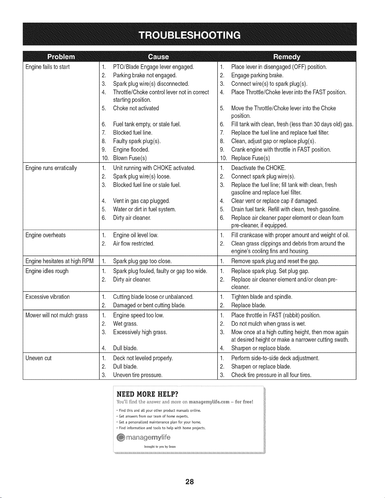
Enginefailsto start
Enginerunserratically
1. PTO/BladeEngageleverengaged.
2. Parkingbrakenotengaged.
3. Sparkplugwire(s)disconnected.
4. Throttle/Chokecontrollevernot incorrect
startingposition.
5. Chokenotactivated
6. Fueltankempty,or stalefuel.
7. BIockedfuel line.
8. Faultyspark plug(s).
9. Engineflooded.
10. BlownFuse(s)
1. Unit runningwith CHOKEactivated.
2. Sparkplugwire(s)loose.
3. Blockedfuel lineor stalefuel.
4. Ventin gas cap plugged.
5. Wateror dirt infuel system.
6. Dirtyair cleaner.
Engineoverheats 1. Engineoil levellow. 1.
2. Air flow restricted. 2.
Enginehesitatesat highRPM 1. Sparkpluggaptoo close. 1.
Engineidles rough 1. Sparkplugfouled,faultyor gaptoo wide. 1.
2. Dirtyair cleaner. 2.
Excessivevibration
Mowerwill not mulchgrass
Unevencut
1. Cuttingbladelooseor unbalanced.
2. Damagedor bentcuttingblade.
1. Enginespeedtoo low.
2. Wetgrass.
3. Excessivelyhighgrass.
4. Dullblade.
1. Decknot leveledproperly.
2. Dullblade.
3. Uneventire pressure.
1. Placeleverindisengaged(OFF) position.
2. Engageparkingbrake.
3. Connectwire(s)to sparkplug(s).
4. PlaceThrottle/Chokeleverintothe FASTposition.
5. MovetheThrottle/Chokeleverintothe Choke
position.
6. Filltankwithclean,fresh(lessthan30 daysold) gas.
7. Replacethe fuel lineandreplacefuel filter.
8. Clean, adjustgap or replaceplug(s).
9. Crank enginewith throttlein FASTposition.
10. ReplaceFuse(s)
1. Deactivatethe CHOKE.
2. Connectsparkplugwire(s).
3. Replacethe fuel line;fill tankwithclean,fresh
gasolineand replacefuel filter.
4. Clear ventor replacecap if damaged.
5. Drainfuel tank. Refillwithclean,freshgasoline.
6. Replaceair cleanerpaperelementor cleanfoam
pre-cleaner,if equipped.
Fillcrankcasewith properamountand weightof oil.
Cleangrass clippingsand debrisfrom aroundthe
engine'scoolingfinsand housing.
Removesparkplugand resetthe gap.
Replacesparkplug.Set pluggap.
Replaceair cleanerelementand/orclean pre-
cleaner.
1. Tightenbladeand spindle.
2. Replaceblade.
1. Placethrottlein FAST(rabbit)position.
2. Do notmulchwhengrass is wet.
3. Mowonce at a highcuttingheight,then mowagain
at desiredheightor makea narrowercuttingswath.
4. Sharpenor replaceblade.
1. Performside-to-sidedeck adjustment.
2. Sharpenor replaceblade.
3. Checktire pressureinallfour tires.
NEE]) MORE HELP?
Find this and all your other product manuals online.
Get answers from our team of home experts.
Get a personalized maintenance plan for your home,
Find information and tools to help with home projects.
28
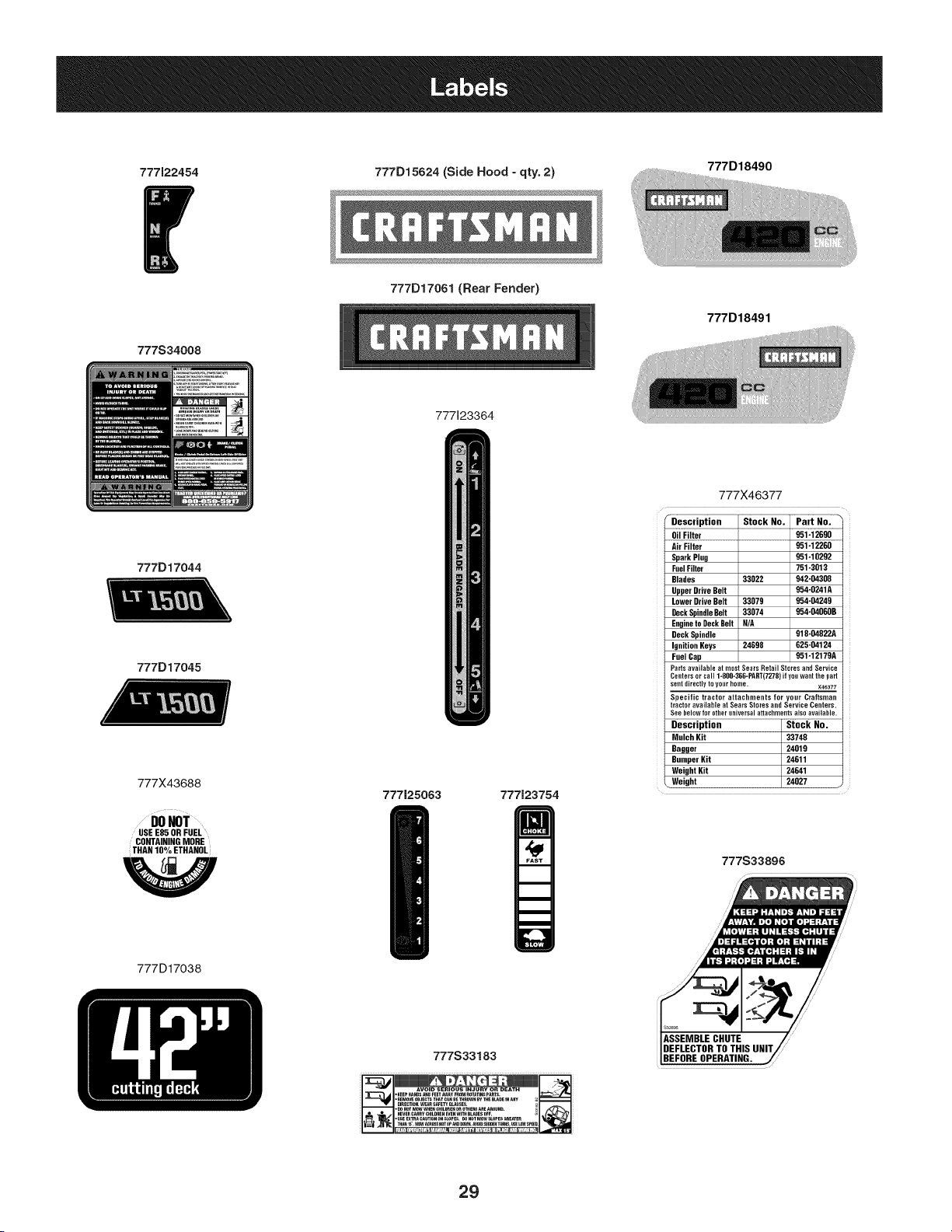
777122454
777D15624 (Side Hood - qty. 2)
777D18490
777S34008
777D17061 (Rear Fender)
777D18491
777123364
777D17044
777D17045
777X43688
DONOT
USEE85 OR FUEL
CONTAININGMORE
THANIO%ETHANOLI
777125063 777123754
777X46377
rDescription
OilFilter
Air Filter 951-12260
SparkPlug 951-10292
FeelFilter 751-3013
Blades 33022 942-04308
UpperDrive Belt 954-0241A
LowerDriveBelt 33079 954-04249
OeckSpindleBelt 33074 954-04060B
Engineto DeckBelt N/A
DeckSpindle 918-04822A
IgnitionKeys 24698 025-04124
FuelCap 951-12179A
Partsavailableat mostSeatsRetailStoresandService
Centersorcall1-800-36G-PART(7279)ifyouwantthepart
sentdirectlytoyogrholue. X46377
Specific tractor attachmentsfor your Craftsman
tractoravailableat SearsStoresand ServiceCeaters.
Seebelowforotheruniversalattachmentsalsoavailable.
Description Stock No.
MulchKit 33748
Bagger 24019
BumperKit 24611
WeightKit 24641
Weight ;
777S33896
777D17038
777S33183
•KEE_HANDS_tgFEETAWAyFROMROT_TINapAR_ "J
ASSEMBLE CHUTE
DEFLECTOR TO THIS UNIT/-
BEFORE OPERATING.
29
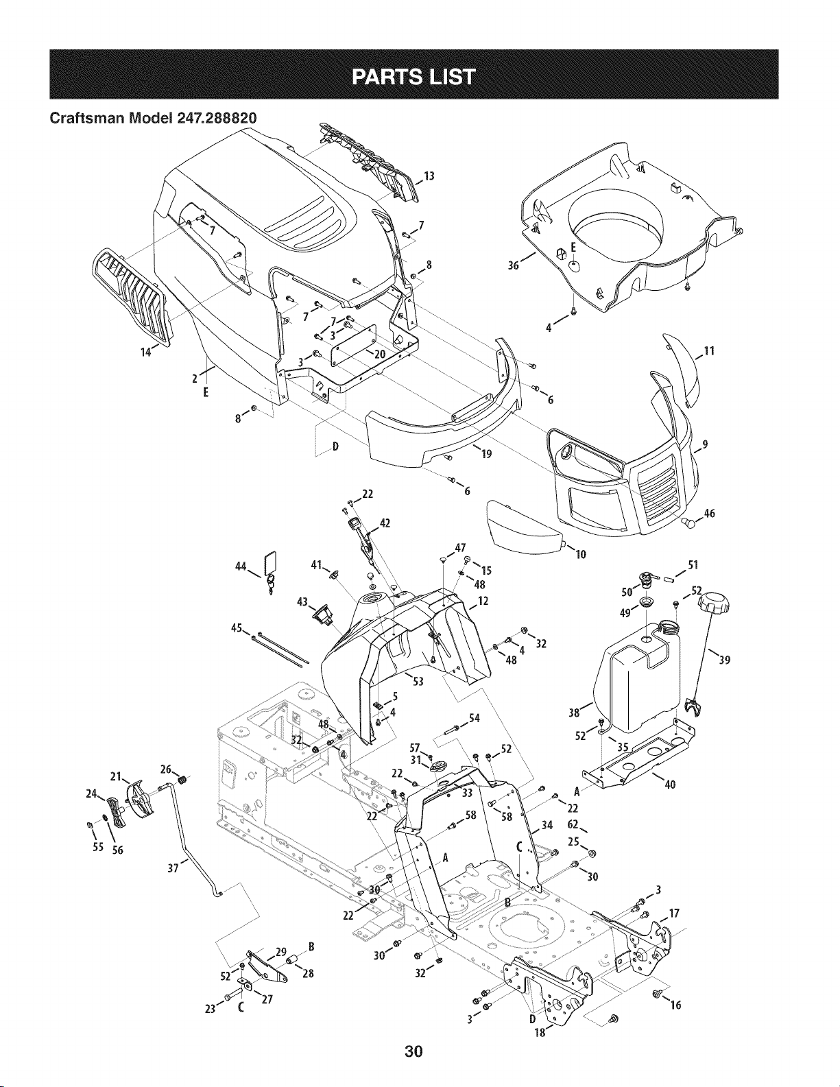
Craftsman IViodel 247.288820
13
\
55 56
42
22
\ \
32
f 5
4
\
\\\
46
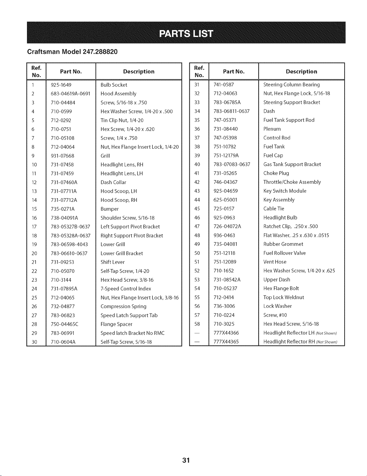
Craftsman Model 247.288820
Ref, I
No,
1 925-1649
2 683-04619A-0691
3 710-04484
4 710-0599
5 712-0292
6 710-0751
7 710-05108
8 712-04064
9 931-07668
10 731-07458
II 731-07459
12 731-07460A
13 731-07711A
14 731-07712A
15 735-0271A
16 738-04091A
17 783-05327B-0637
18 783-05328A-0637
19 783-06598-4043
20 783-06610-0637
21 731-09253
22 710-05070
23 710-3144
24 731-07895A
25 712-04065
26 732-04877
27 783-06823
28 750-04465C
29 783-06991
30 710-0604A
Part No, Description
Bulb Socket
Hood Assembly
Screw, 5/16-18 x .750
Hex Washer Screw, 1/4-20 x .500
Tin Clip Nut, 1/4-20
Hex Screw, 1/4-20 x .620
Screw, 1/4 x .750
Nut, Hex Flange Insert Lock, 1/4-20
Grill
Headlight Lens, RH
Headlight Lens, LH
Dash Collar
Hood Scoop, LH
Hood Scoop, RH
Bumper
Shoulder Screw, 5/16-18
Left Support Pivot Bracket
Right Support Pivot Bracket
Lower Grill
Lower Grill Bracket
Shift Lever
Self-Tap Screw, 1/4-20
Hex Head Screw, 3/8-16
7-Speed Control Index
Nut, Hex Flange Insert Lock, 3/8-16
Compression Spring
Speed Latch Support Tab
Flange Spacer
Speed latch Bracket No RMC
Self-Tap Screw, 5/16-18
Ref, [
No,
31 741-0587
32 712-04063
33 783-06785A
34 783-06811-0637
35 747-05371
36 731-08440
37 747-05398
38 751-10782
39 751-12179A
40 783-07083-0637
41 731-05265
42 746-04367
43 925-04659
44 625-05001
45 725-0157
46 925-0963
47 726-04072A
48 936-0463
49 735-04081
50 751-12118
51 751-12089
52 710-1652
53 731-08542A
54 710-05237
55 712-0414
56 736-3006
57 710-0224
58 710-3025
-- 777X44366
-- 777X44365
Part No, Description
Steering Column Bearing
Nut, Hex Flange Lock, 5/16-18
Steering Support Bracket
Dash
Fuel Tank Support Rod
Plenum
Control Rod
FuelTank
Fuel Cap
Gas Tank Support Bracket
Choke Plug
Throttle/Choke Assembly
Key Switch Module
Key Assembly
Cable Tie
Headlight Bulb
Ratchet Clip, .250 x .500
Flat Washer, .25 x .630 x .0515
Rubber Grommet
Fuel Rollover Valve
Vent Hose
Hex Washer Screw, 1/4-20 x .625
Upper Dash
Hex Flange Bolt
Top Lock Weldnut
LockWasher
Screw, #10
Hex Head Screw, 5/16-18
Headlight Reflector LH (NotShown)
Headlight Reflector RH (NotShown)
31
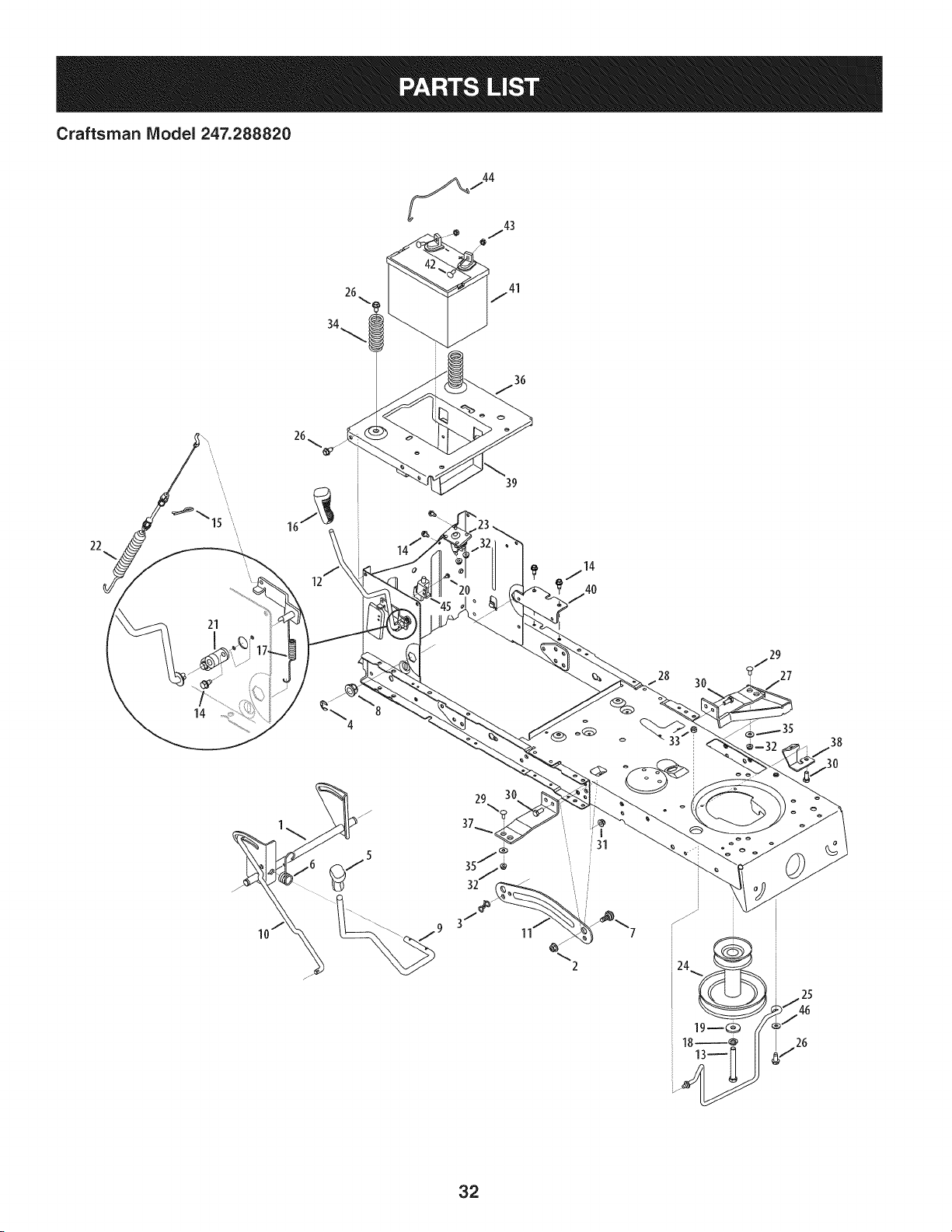
Craftsman Model 247.288820
26
34
22
21
14
12
39
i31
2
_29
? 27
32
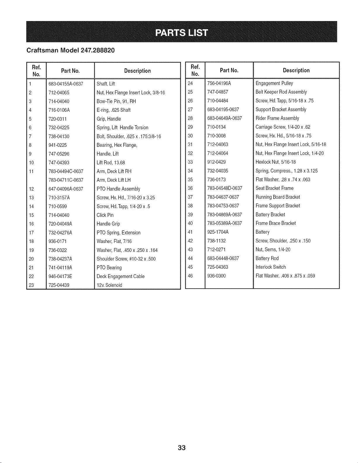
Craftsman Model 247.288820
Ref. I
No.
1 683-04155A-0637
2 712-04065
3 714-04040
4 716-0106A
5 720-0311
6 732-04225
7 738-04130
8 941-0225
9 747-05296
10 747-04393
11 783-04494C-0637
783-04711C-0637
12 647-04096A-0637
13 710-3157A
14 710-0599
15 714-04040
16 720-04049A
17 732-04276A
18 936-0171
19 736-0322
20 738-04237A
21 741-04119A
22 946-04173E
23 725-04439
Part No. Description
Shaft, Lift
Nut, HexFlangeInsertLock, 3/8-16
Bow-TiePin,91, RH
E-ring,.625Shaft
Grip,Handle
Spring,Lift HandleTorsion
Bolt, Shoulder,.625x .175:3/8-16
Bearing,HexFlange,
Handle,Lift
Lift Rod,13.68
Arm, DeckLift RH
Arm, DeckLift LH
PTOHandleAssembly
Screw,Hx. Hd.,7/16-20x 3.25
Screw,Hd.Tapp,1/4-20x .5
Click Pin
HandleGrip
PTOSpring,Extension
Washer,Flat,7/16
Washer,Fiat, .450x .250x .164
ShoulderScrew,#10-32x .500
PTOBearing
DeckEngagementCable
12v.Solenoid
Ref. I
No.
24 756-04196A
25 747-04857
26 710-04484
27 683-04195-0637
28 683-04649A-0637
29 710-0134
30 710-3008
31 712-04063
32 712-04064
33 912-0429
34 732-04035
35 736-0173
36 783-04548D-0637
37 783-04637-0637
38 783-04753-0637
39 783-04869A-0637
40 783-05389A-0637
41 925-1704A
42 738-1132
43 712-0271
44 683-04448-0637
45 725-04363
46 936-0300
Part No. Description
EngagementPulley
Belt KeeperRodAssembly
Screw,Hd.Tapp,5/16-18x .75
SupportBracketAssembly
RiderFrameAssembly
CarriageScrew,1/4-20x .62
Screw,Hx. Hd.,5/16-18x .75
Nut, HexFlangeInsert Lock,5/16-18
Nut, HexFlangeInsert Lock,1/4-20
HexlockNut,5/16-18
Spring,Compress.,1.28x 3.125
FlatWasher,.28 x .74x .063
SeatBracketFrame
RunningBoardBracket
FrameSupportBracket
BatteryBracket
FrameBraceBracket
Battery
Screw,Shoulder,.250x .150
Nut,Sems, 1/4-20
BatteryRod
InterlockSwitch
FlatWasher,.406x .875x .059
33
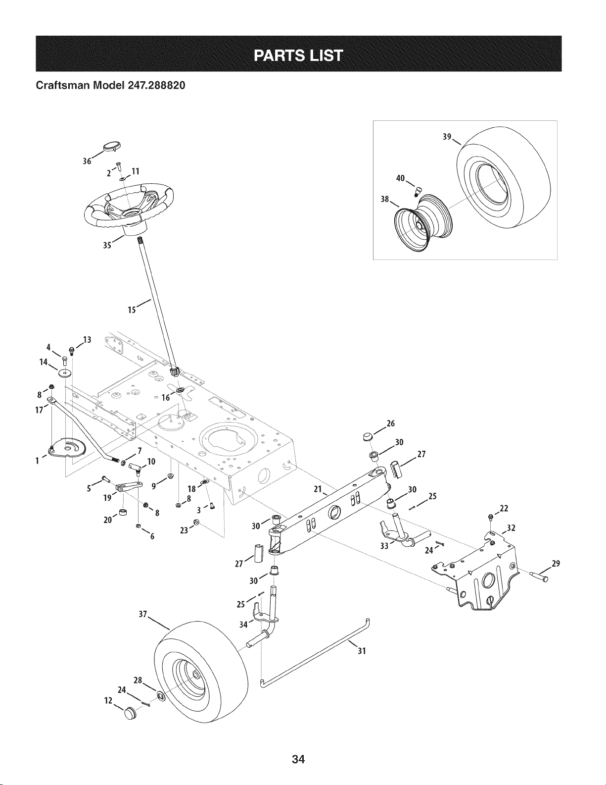
Craftsman IViodel 247.288820
21
30
25
22
................ 33 _ /_ ........................
34
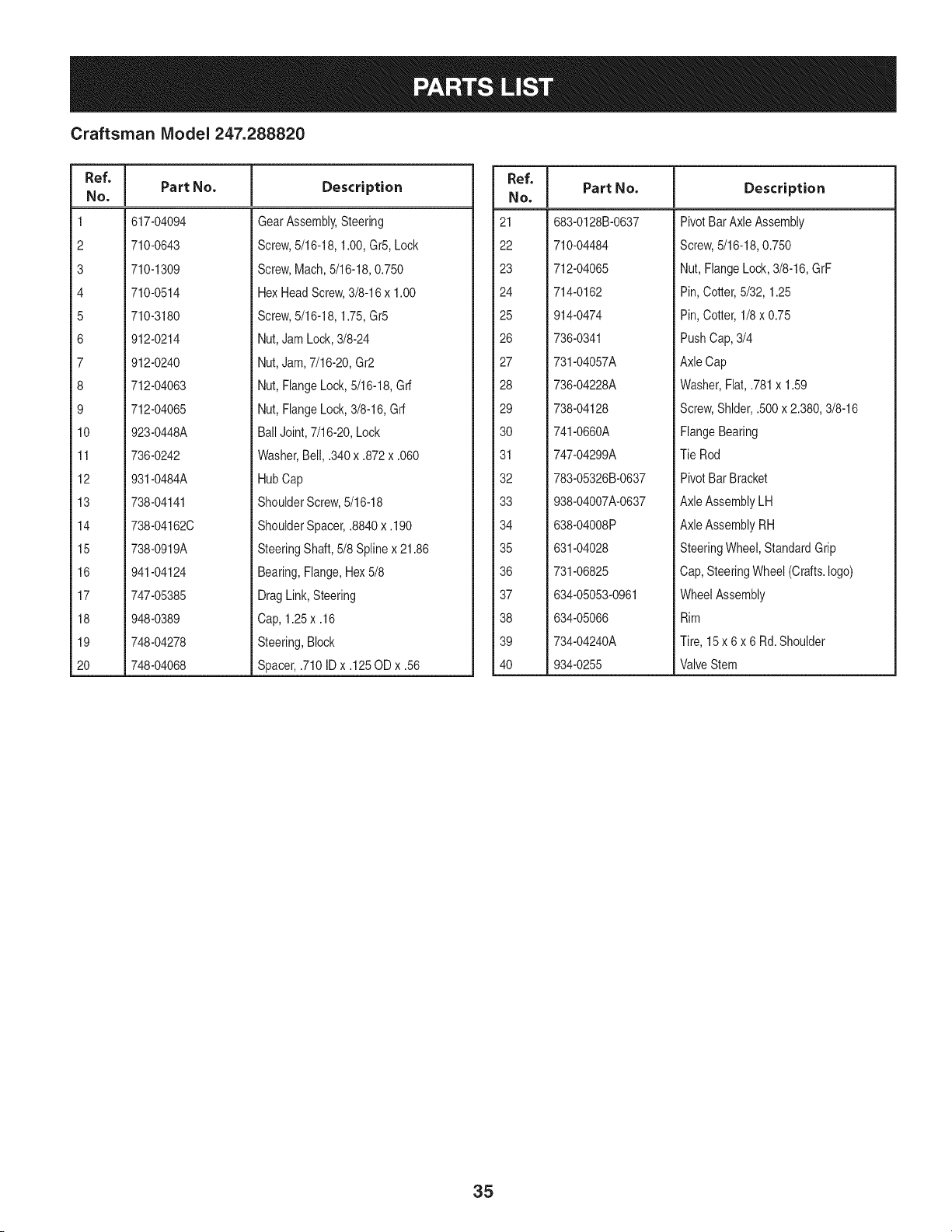
Craftsman Model 247.288820
Ref, I
No.
1 617-04094
2 710-0643
3 710-1309
4 710-0514
5 710-3180
6 912-0214
7 912-0240
8 712-04063
9 712-04065
10 923-0448A
11 736-0242
12 931-0484A
13 738-04141
14 738-04162C
15 738-0919A
16 941-04124
17 747-05385
18 948-0389
19 748-04278
20 748-04068
Part No. Description
GearAssembly,Steering
Screw,5/16-18,1.00,Gr5,Lock
Screw,Mach,5/16-18,0.750
HexHeadScrew,3/8-16x 1.00
Screw,5/16-18,1.75,Gr5
Nut,JamLock,3/8-24
Nut,Jam,7/16-20,Gr2
Nut,FlangeLock,5/16-18,Grf
Nut,FlangeLock,3/8-16,Grf
BallJoint,7/16-20,Lock
Washer,Bell, .340x .872x .060
HubCap
ShoulderScrew,5/16-18
ShoulderSpacer,.8840 x.190
SteeringShaft,5/8 Splinex 21.86
Bearing,Flange,Hex5/8
DragLink,Steering
Cap, 1.25x .16
Steering,Block
Spacer,.710ID x .125OD x .56
Ref, I
No.
21 683-0128B-0637
22 710-04484
23 712-04065
24 714-0162
25 914-0474
26 736-0341
27 731-04057A
28 736-04228A
29 738-04128
30 741-0660A
31 747-04299A
32 783-05326B-0637
33 938-04007A-0637
34 638-04008P
35 631-04028
36 731-06825
37 634-05053-0961
38 634-05066
39 734-04240A
40 934-0255
Part No, Description
PivotBarAxle Assembly
Screw,5/16-18,0.750
Nut, FlangeLock,3/8-16,GrF
Pin, Cotter,5/32, 1.25
Pin, Cotter,1/8 x 0.75
PushCap,3/4
AxleCap
Washer,Flat,.781x 1.59
Screw,Shlder,.500x 2.380,3/8-16
FlangeBearing
Tie Rod
PivotBar Bracket
AxleAssemblyLH
AxleAssemblyRH
SteeringWheel,StandardGrip
Cap,SteeringWheel (Crafts.logo)
WheelAssembly
Rim
Tire, 15 x 6 x 6 Rd.Shoulder
ValveStem
35
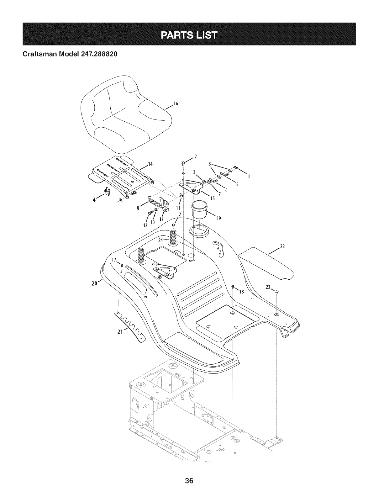
Craftsman IViodel 247.288820
\
\
36
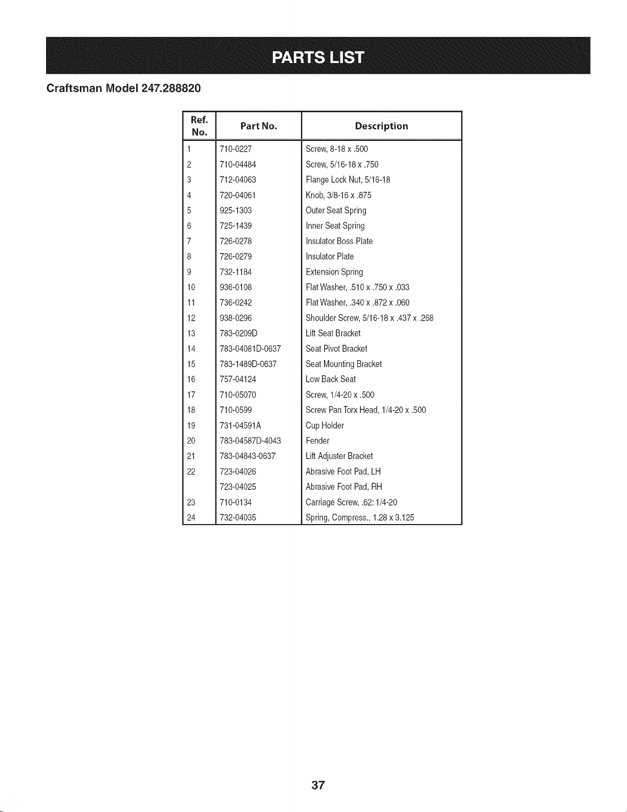
Craftsman Model 247.288820
Ref. I
No,
1 710-0227
2 710-04484
3 712-04063
4 720-04061
5 925-1303
6 725-1439
7 726-0278
8 726-0279
9 732-1184
10 936-0108
11 736-0242
12 938-0296
13 783-0209D
14 783-04081D-0637
15 783-1489D-0637
16 757-04124
17 710-05070
18 710-0599
19 731-04591A
20 783-04587D-4043
21 783-04843-0637
22 723-04026
723-04025
23 710-0134
24 732-04035
Part No. Description
Screw,8-18 x .500
Screw,5/16-18x .750
FlangeLockNut, 5/16-18
Knob,3/8-16x .875
OuterSeat Spring
InnerSeatSpring
InsulatorBossPlate
InsulatorPlate
ExtensionSpring
FiatWasher,.510x .750x .033
FlatWasher,.340x .872x .060
ShoulderScrew,5/16-18x .437x .268
Lift SeatBracket
Seat PivotBracket
Seat MountingBracket
Low BackSeat
Screw,1/4-20x .500
ScrewPanTorxHead,1/4-20x .500
Cup Holder
Fender
Lift AdjusterBracket
AbrasiveFootPad,LH
AbrasiveFootPad,RH
CarriageScrew,.62:1/4-20
Spring,Compress.,1.28x 3.125
37
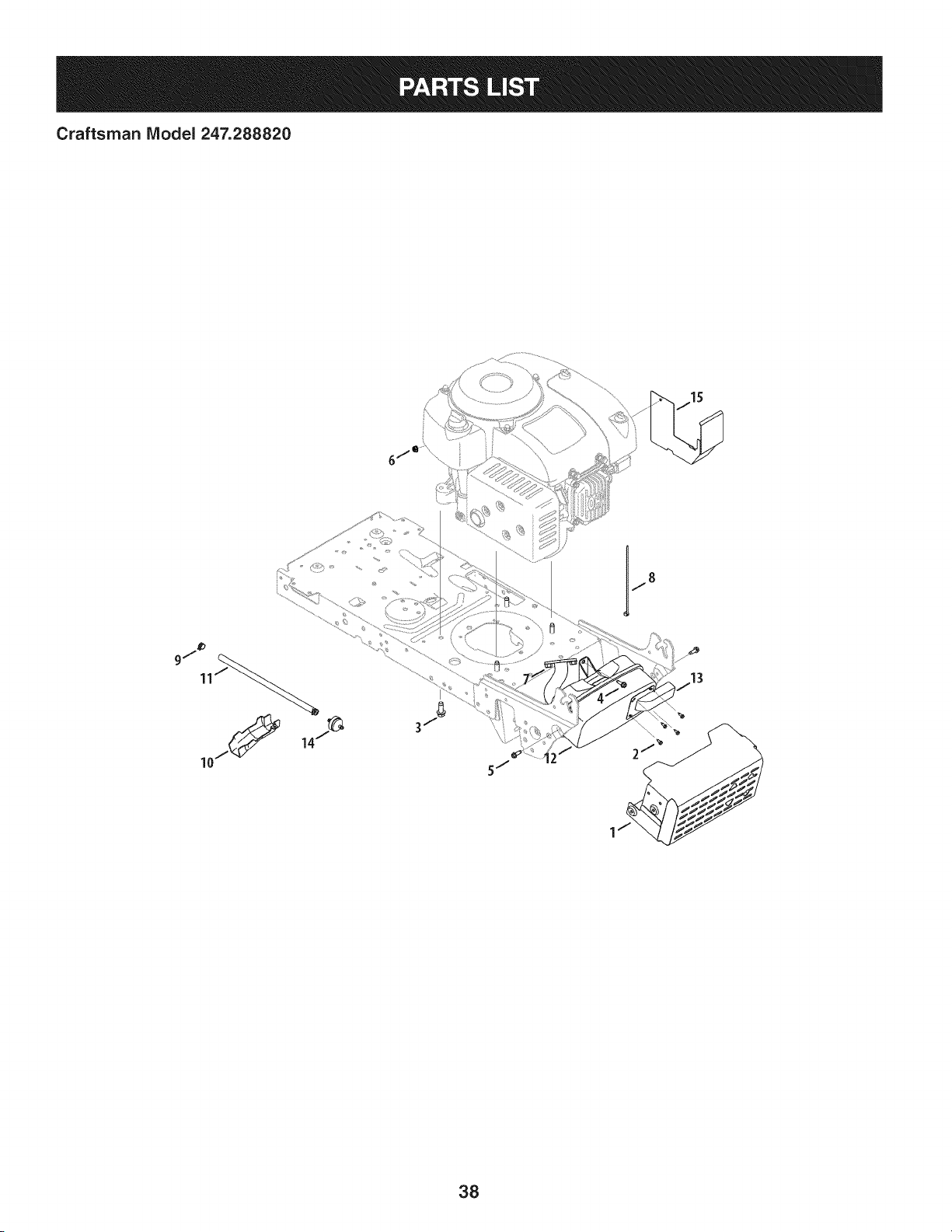
Craftsman IViodel 247.288820
9/_ _ ......
11J_ .......................
38

Craftsman Model 247.288820
I
Fief. I Part No.
1 683-04549
2 710-0227
3 710-04683A
4 710-0599
5 710-0642
6 712-04064
7 712-3086
8 725-0157
9 726-0205
10 731-05628
II 751-10349-28
12 751-12836
13 751-14284
14 751-3013
15 783-08122
N/A
Description
Muffler Shield Assembly with Weld
Screw, 8-18 x .500
Screw, 3/8-16 x 1.0
Screw, 1/4-20 x .500
Screw, 1/4-20 x .750
Flangelock Nut, 1/4-20
Flange Nut, M8-1.25
Cable Tie
Clamp Hose, .490 diameter
Oil Drain Sleeve
Fuel Hose, Low Permeation
Muffler
Muffler Deflector
Fuel Filter
Deflector Bracket
Engine (See breakdown)
Craftsman Model No. 4P9OHU
39
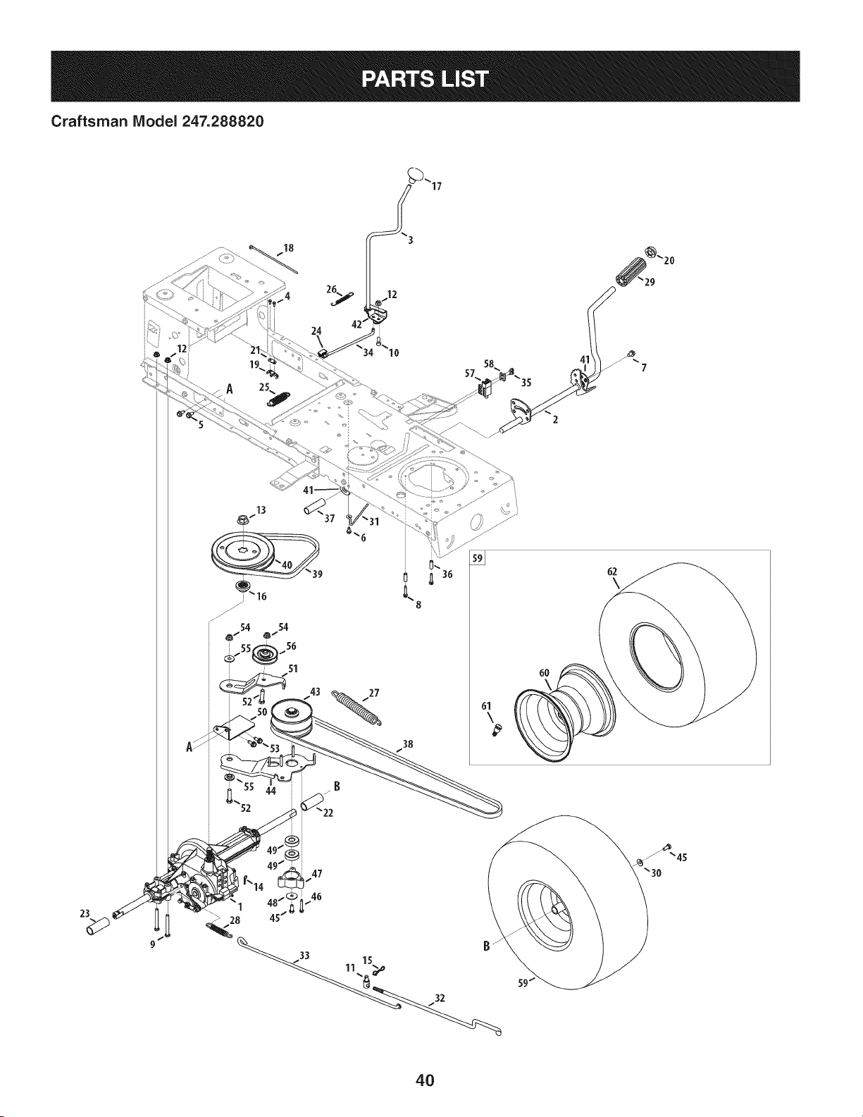
Craftsman Model 247.288820
18
24
8
27
38
6O
62
\
23
47
1 "
> 28
1 15
4O

Craftsman Model 247.288820
Ref, I
NO,
1 918-04566
2 647-04034C-0637
3 647-04266
4 710-0227
5 710-04484
6 710-0599
7 710-0604A
8 710-0809
9 710-0176
10 710-3008
11 711-06103
12 712-04063
13 712-0700
14 914-0209
15 714-04040
16 718-04407
17 720-04028
18 725-0157
19 725-1644
20 726-0214
21 926-0320
22 731-04602
23 731-04604
24 731-06894
25 732-04306
26 732-04488
27 732-04746
28 732-0716D
29 735-0239
30 736-0242
31 747-04969
32 747-05186
Part No. Description
TransmissionDriveAssembly
PedalAssembly
Shaft LeverAssembly
Screw,8-18:0.500
Screw,5/16-18x .750
Screw,1/4-20x 0.500
Screw,5/16-18x 0.625
Screw,1/4-20x 1.250
HexScrew,5/16-18x 2.75
HexScrew,5/16-18x .75
Ferrule,3/8-24X .375DIA.
FlangelockNut, 5/16-18
FlangeNut, 9/16-18
Cotter Pin INT-.125DIA
Bow-TieCotter Pin
PulleyHub,5/8SPLINE
Shift Knob
CableTie
Short SpringSwitch
PushCap,5/8
PlateInsulatorNut
Sleeve,.758x .821x 3.3125
Sleeve,.758x .821x 2.4375
Shift BearingPlate
SpringExtension,.80ODx 3.28LG
SpringExtension,.38ODx 3.25LG
SpringExtension,.94ODx 6.75LG
SpringExtension,.59ODx 4.00LG
FootPad,4.0 LONG
BellWasher,.340x .872x .060
Belt KeeperRod
VariableSpeedControl Rod
Ref. I
No,
33 747-05188
34 747-05244
35 738-04237A
36 750-0566A
37 750-0802
38 954-04249A
39 954-0241A
40 956-04002
41 783-04536B-0637
42 783-04595A
43 956-04015A
44 683-04206
45 710-05339
46 710-0778
47 718-04261
48 736-0362
49 941-0600
50 683-04176A
51 683-04207
52 710-0347
53 710-1260A
54 712-04065
55 938-0347
56 756-04325
57 725-04363
58 17962
59 634-04324
60 634-04369-4042
61 934-0255
62 734-04241
-- 725-04567G
Part No. Description
BrakeRod
Shift Rod
ShoulderScrew,#10-32x .500
Spacer,.260 x .375x 1.030LG
Spacer,.640 IDx .76OD x 2.63
V Belt, 5L:70.90 POLY
V Belt, 5L:35.25 POLY
Trans.Pulley
PedalSupportBracket
ShaftAdjustBracket
VariableSpeed PulleyAssembly
BracketAssembly
SEMSScrew,5/16-24x .750
Screw,1/4-20x 1.500
BearingCup
FlatWasher,.330x 1.25x .06:HT
Ball Bearing,17x 40x 12
TransmissionBracketAssembly
Idler BracketAssembly
HexScrew,3/8-16x 1.75
Screw,5/16-18x 0.750
FlangeLockNut, 3/8-16
ShoulderSpacer,.625IDx .169
Idler Pulley
SwitchInterlock
PlateSwitch
WheelAssembly,20 x 8 x 8
RimAssembly
ValveStem
Tire, 20 x 8 x 8 Rd.Sh.
WiringHarness(Not Shown)
41
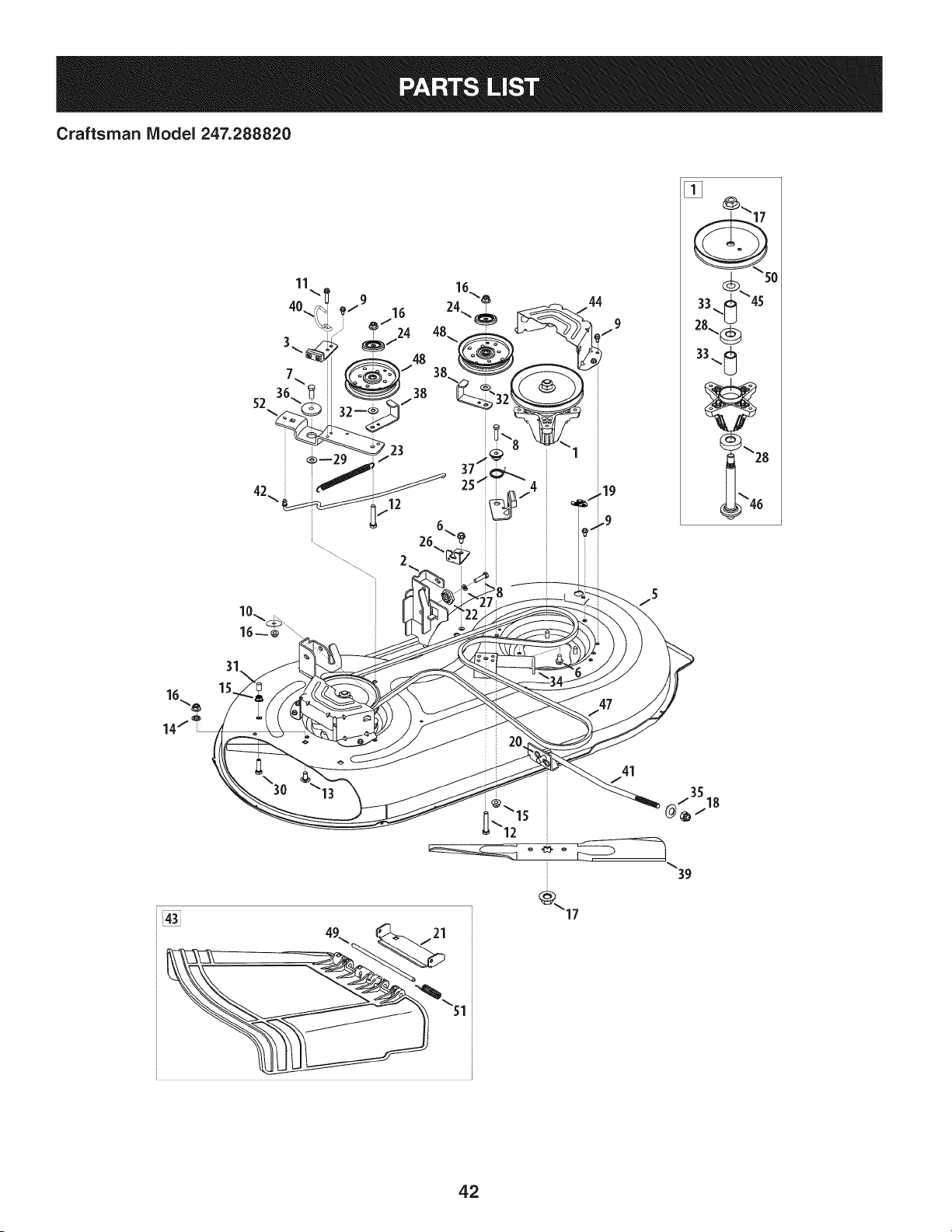
Craftsman Model 247.288820
10\®\
44
9
/
51
i
_\15
12
41
i
35
@_/18
39
42
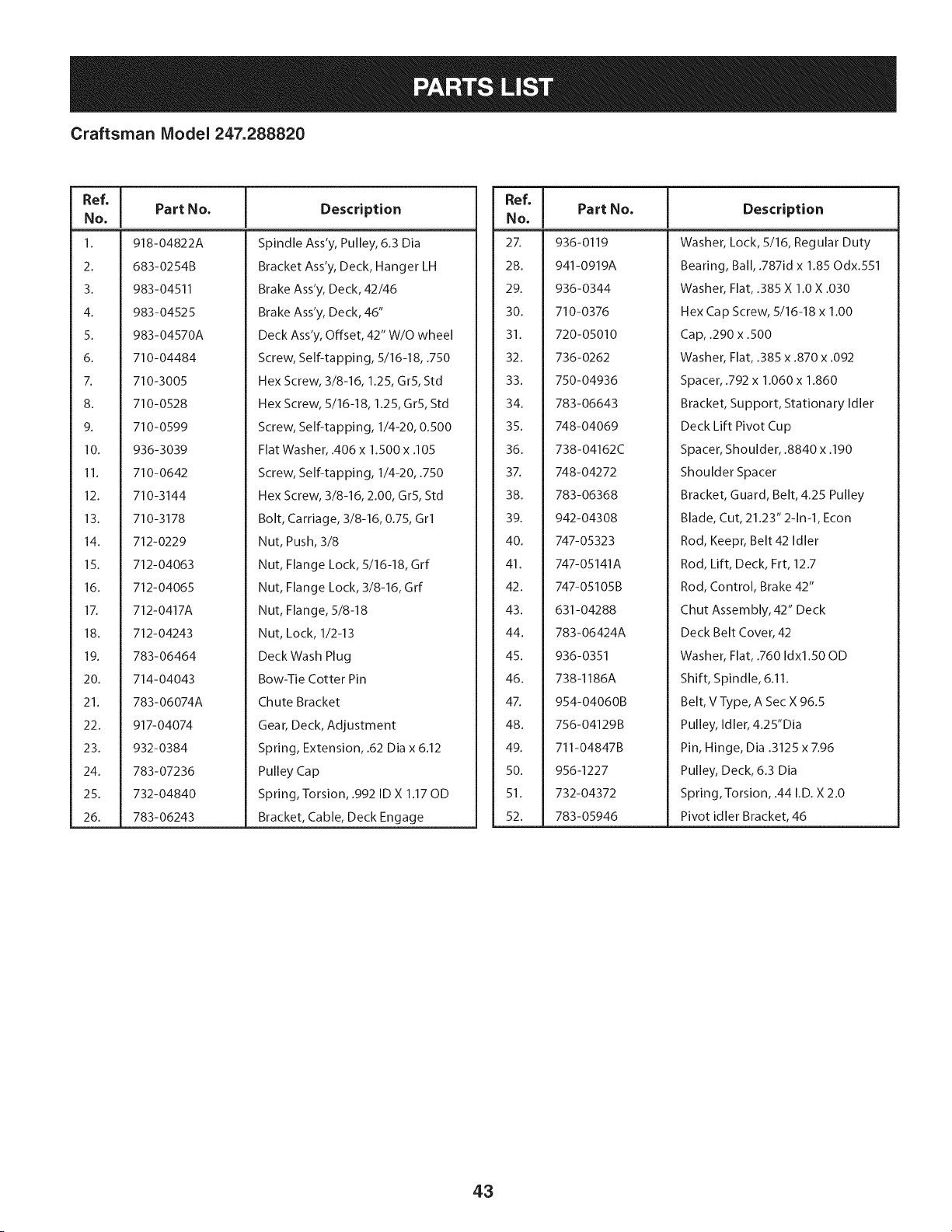
Craftsman Model 247.288820
Ref, I
No,
1. 918-04822A
2. 683-0254B
3. 983-04511
4. 983-04525
5. 983-04570A
6. 710-04484
7. 710-3005
8. 710-0528
9. 710-0599
10. 936-3039
11. 710-0642
12. 710-3144
13. 710-3178
14. 712-0229
15. 712-04063
16. 712-04065
17. 712-0417A
18. 712-04243
19. 783-06464
20. 714-04043
21. 783-06074A
22. 917-04074
23. 932-0384
24. 783-07236
25. 732-04840
26. 783-06243
Part No. Description
Spindle Ass'y, Pulley, 6.3 Dia
Bracket Ass'y, Deck, Hanger LH
Brake Ass'y, Deck, 42/46
Brake Ass'y, Deck, 46"
Deck Ass'y, Offset, 42" W/O wheel
Screw, Self-tapping, 5/16-18, .750
Hex Screw, 3/8-16, 1.25, Gr5, Std
Hex Screw, 5/16-18, 1.25, Gr5, Std
Screw, Self-tapping, 1/4-20, 0.500
Flat Washer, .406 x 1.500 x .105
Screw, Self-tapping, 1/4-20, .750
Hex Screw, 3/8-16, 2.00, Gr5, Std
Bolt, Carriage, 3/8-16, 0.75, Grl
Nut, Push, 3/8
Nut, Flange Lock, 5/16-18, Grf
Nut, Flange Lock, 3/8-16, Grf
Nut, Flange, 5/8-18
Nut, Lock, 1/2-13
Deck Wash Plug
Bow-Tie Cotter Pin
Chute Bracket
Gear, Deck, Adjustment
Spring, Extension, .62 Dia x 6.12
Pulley Cap
Spring, Torsion, .992 ID X 1.17 OD
Bracket, Cable, Deck Engage
Ref, I
No,
2X 936-0119
28. 941-0919A
29. 936-0344
30. 710-0376
31. 720-05010
32. 736-0262
33. 750-04936
34. 783-06643
35. 748-04069
36. 738-04162C
37. 748-04272
38. 783-06368
39. 942-04308
40. 747-05323
41. 747-05141A
42. 747-05105B
43. 631-04288
44. 783-06424A
45. 936-0351
46. 738-1186A
47. 954-04060B
48. 756-04129B
49. 711-04847B
50. 956-1227
51. 732-04372
52. 783-05946
Part No. Description
Washer, Lock, 5/16, Regular Duty
Bearing, Ball, .787id x 1.85 Odx.551
Washer, Flat, .385 X 1.0 X .030
Hex Cap Screw, 5/16-18 x 1.00
Cap, .290 x .500
Washer, Flat, .385 x .870 x .092
Spacer, .792 x 1.060 x 1.860
Bracket, Support, Stationary Idler
Deck Lift Pivot Cup
Spacer, Shoulder, .8840 x .190
Shoulder Spacer
Bracket, Guard, Belt, 4.25 Pulley
Blade, Cut, 21.23" 2-1n-1, Econ
Rod, Keepr, Belt 42 Idler
Rod, Lift, Deck, Frt, 12.7
Rod, Control, Brake 42"
Chut Assembly, 42" Deck
Deck Belt Cover, 42
Washer, Flat, .760 Idxl.50 OD
Shift, Spindle, 6.11.
Belt, V Type, A Sec X 96.5
Pulley, Idler, 4.25"Dia
Pin, Hinge, Dia .3125 x 7.96
Pulley, Deck, 6.3 Dia
Spring,Torsion, .44 I.D. X 2.0
Pivot idler Bracket, 46
43
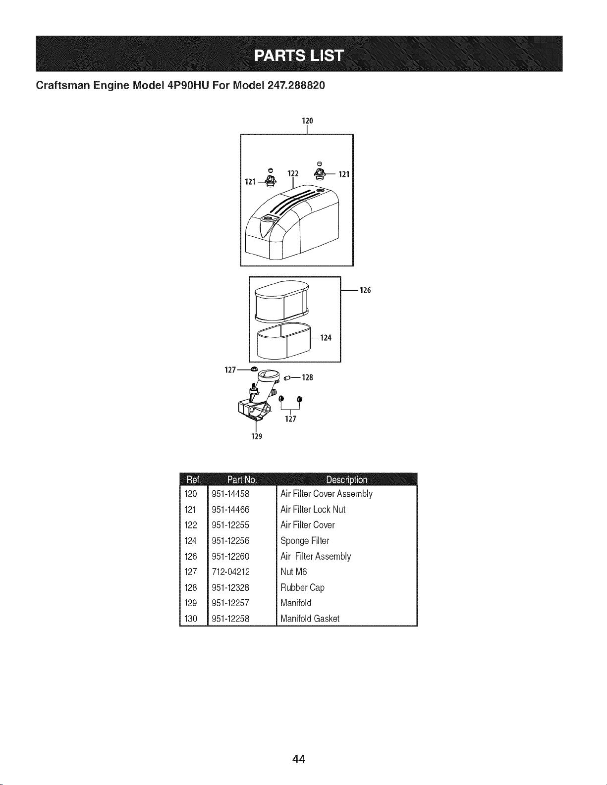
Craftsman Engine Model 4P90HU For Model 247.288820
120
[
0
122 _ 121
121--_
_124
127__ __
;Y 127
129
-- 126
m
120
121
122
124
126
127
128
129
130
951-14458
951-14466
951-12255
951-12256
951-12260
712-04212
951-12328
951-12257
951-12258
D = _ O II
Air FilterCoverAssembly
Air FilterLockNut
Air FilterCover
SpongeFilter
Air FilterAssembly
NutM6
RubberCap
Manifold
ManifoldGasket
44
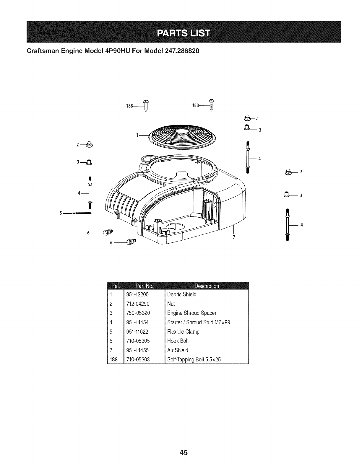
Craftsman Engine Model 4P90HU For Model 247.288820
I
m
1
2
3
4
5
6
7
188
951-12205
712-04290
750-05320
951-14454
951-11622
710-05305
951-14455
710-05303
D = O O
DebrisShield
Nut
EngineShroudSpacer
Starter/ ShroudStud M6x99
FlexibleClamp
HookBolt
Air Shield
Self-TappingBolt5.5x25
45
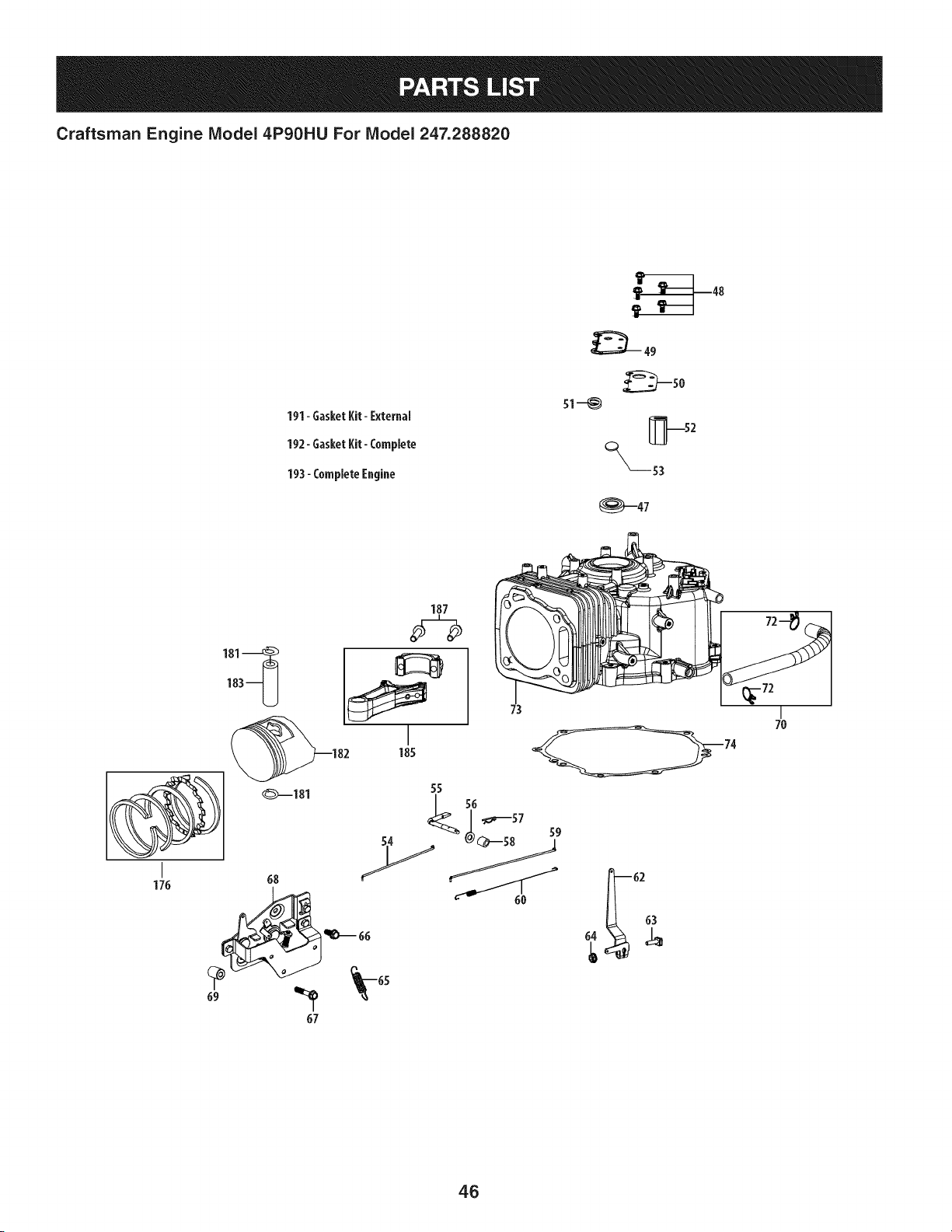
Craftsman Engine Model 4P90HU For Model 247.288820
191- GasketKit- External
192- GasketKit- Complete
193- Complete Engine
s1-_
_---53
_47
187
1_3-U
_181
I
176 68
55
I
7O
46
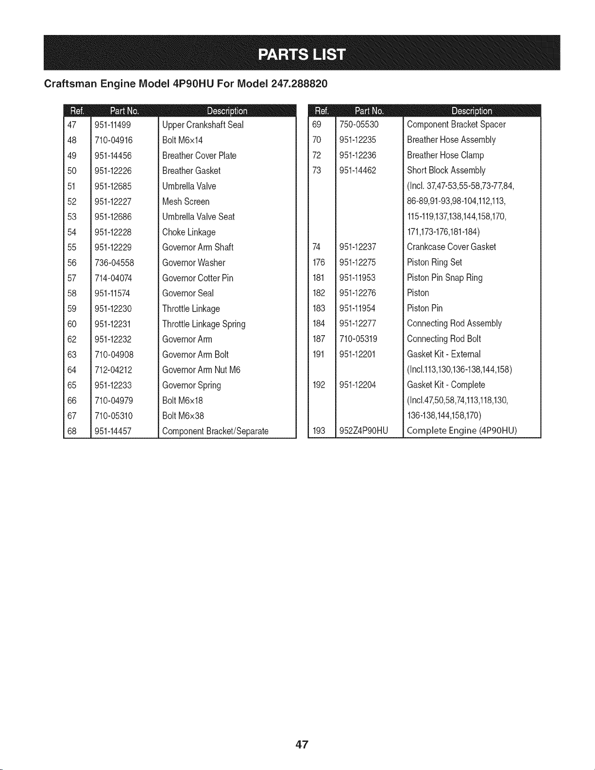
Craftsman Engine IViodel 4P90HU For IViodel 247.288820
m
47
48
49
5O
51
52
53
54
55
56
57
58
59
6O
62
63
64
65
66
67
68
951-11499
710-04916
951-14456
951-12226
951-12685
951-12227
951-12686
951-12228
951-12229
736-04558
714-04074
951-11574
951-12230
951-12231
951-12232
710-04908
712-04212
951-12233
710-04979
710-05310
951-14457
D = O
UpperCrankshaftSeal
Bolt M6x14
BreatherCoverPlate
BreatherGasket
UmbrellaValve
MeshScreen
UmbrellaValveSeat
ChokeLinkage
GovernorArm Shaft
GovernorWasher
GovernorCotterPin
GovernorSeal
ThrottleLinkage
ThrottleLinkageSpring
GovernorArm
GovernorArm Bolt
GovernorArm Nut M6
GovernorSpring
Bolt M6x18
Bolt M6x38
ComponentBracket/Separate
m
69
7O
72
73
74
176
181
182
183
184
187
191
192
193
750-05530
951-12235
951-12236
951o14462
951-12237
951-12275
951-11953
951-12276
951-11954
951-12277
710-05319
951-12201
951-12204
952Z4P90HU
m = O
ComponentBracketSpacer
BreatherHoseAssembly
BreatherHoseClamp
ShortBlockAssembly
(Incl.37,47-53,55-58,73-77,84,
86-89,91-93,98-104,112,113,
115-119,137,138,144,158,170,
171,173-176,181-184)
CrankcaseCoverGasket
PistonRingSet
PistonPinSnap Ring
Piston
PistonPin
ConnectingRodAssembly
ConnectingRodBolt
GasketKit- External
(Inc1.113,130,136-138,144,158)
GasketKit- Complete
(Incl.47,50,58,74,113,118,130,
136-138,144,158,170)
Complete Engine (4PgOHU)
4.7
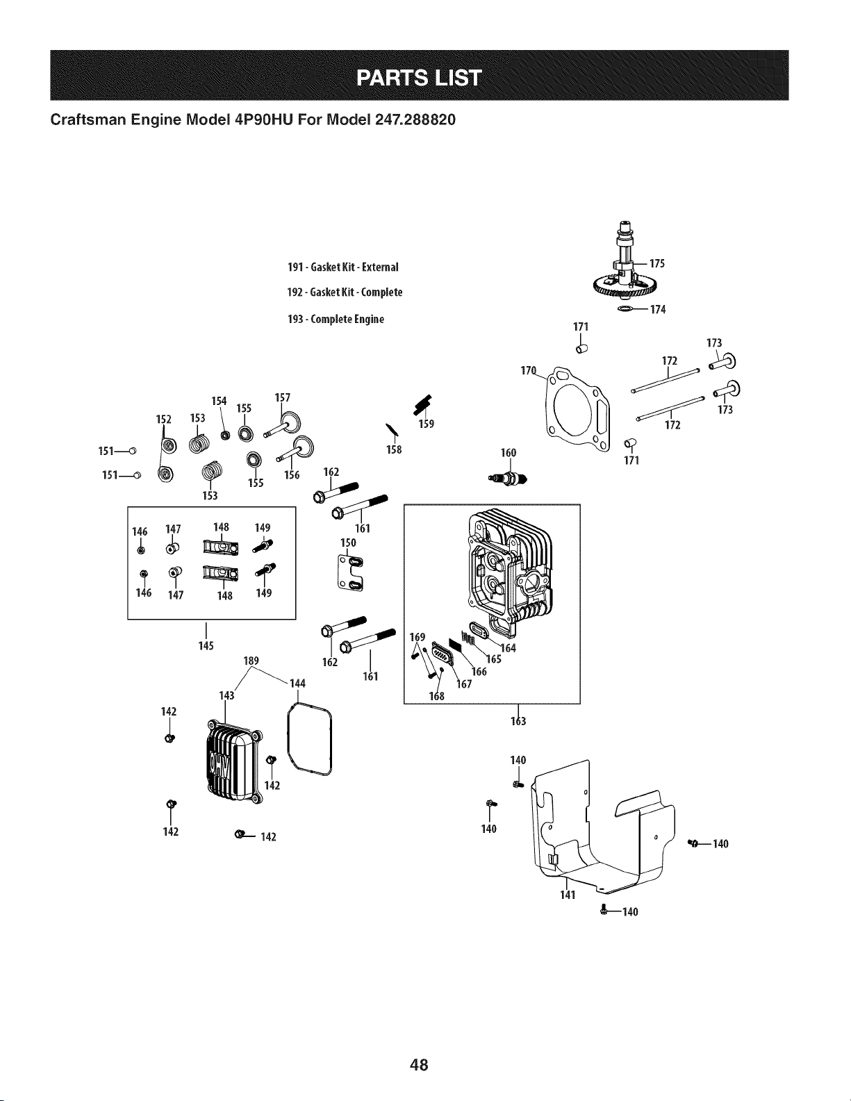
Craftsman Engine Model 4P90HUFor Model 247.288820
191- Gasket Kit- External
192- GasketKit- Complete
193- Complete Engine
154 157
152_ _153 __ '_
I58
i_5 15oio2
153
1_ 147 148 149
147 148 149
161
150
142
142
I
145
161
_--- 142
159
160
166
171
173
172 _)
173
172
171
1401
141
_140
48

Craftsman Engine IViodel 4P90HU For IViodel 247.288820
m
140
141
142
143
144
145
146
147
148
149
150
151
152
153
154
155
156
157
158
159
159
160
161
162
710-05315
951-12265
710-05316
951-12266
951-12267
951-11981
751-11124
751-11123
951-11966
710-04962
D = O 0
BoltM5xlO
Cowl
ValveCoverBolt
ValveCover
ValveCoverRing
RockerArmAssembly
Jam Nut
FulcrumNut
RockerArm
RockerArmStud
951-12268
951-12269
951-12080
951-12078
951-11964
951-12077
951-11337
951-11337
951-12271
951-14459
951-14464
951-10292
710-05317
710-05318
PushRodGuide
ExhaustValveAdjuster
ExhaustValveSpringRetainer
ValveSpring
IntakeValveSeal
ValveSpringRetainer
ValveKit
ValveKit
ExhaustPipeGasket
MuffStud M8x47
MufflerStudAssembly
SparkPlug/F6Rtc
BoltM10x1.25x85
Bolt/M10x1.25x65
m
163
164
165
166
167
168
169
170
171
172
173
174
175
189
191
192
193
951-12202
951-14463
951-14460
951-12775
951-12776
951-12777
736-04629
710-05337
951-12273
715-04122
951-11335
951-11962
736-04561
951-12274
951-12197
951-12201
951-12204
952Z4P90HU
D = O O
CylinderHead Kit
(Incl.114,154,161,162,170)
CylinderHeadAssembly
(Incl.137-139,144,146-159,
Air ValveCore
StrainerClip
SecondAirValveFilterElement
The Air ValveBonnet
Washer
ScrewM5x12
CylinderHeadGasket
CylinderHead Dowel12x16
PushRodKit
Tappet
CamshaftThrustWasher
CamshaftAssembly
ValveCoverKit
GasketKit- External
(IncM13,130,136-138,144,158)
GasketKit- Complete
(Incl.47,50,58,74,113,118,130,
136-138,144,158,170)
CompleteEngine(4PgOHU)
49
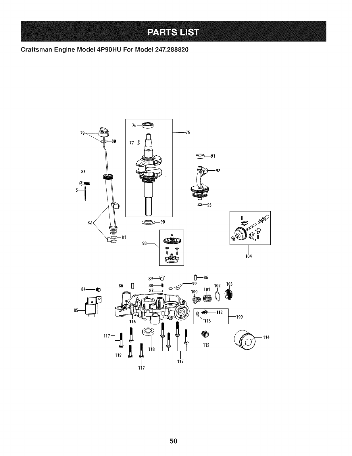
Craftsman Engine Model 4P90HU For Model 247.288820
79_ -8(
2.'
sl 3
82 _81
76_
--75
104
116
117
5O

Craftsman Engine IViodel 4P90HU For IViodel 247.288820
m
5
75
76
77
79
8O
81
82
83
84
85
86
87
88
89
9O
91
92
93
951-11622
951-12238
951-11969
951-10307
951-12239
951-12241
951-12363
951-12240
710-04980
710-05311
951-12242
715-04121
951-12243
951-12244
710-05312
736-04557
951-12245
751-12246
736-04559
D = I! O
FlexibleClamp
CrankshaftAssembly
MainBearing
WoodruffKey
DipstickAssembly
UpperO-Ring
LowerO-Ring
Oil FillTubeAssembly
Bolt M6x35
Oil DrainPlug
Regulator
DowelPin8x14
Ball6.35
Spring
Bolt
CrankshaftThrustWasher
BalanceableShaftBearing
BalanceableShaftAssembly
BalanceableThrustWasher
m
98
99
1CO
101
102
103
104
112
113
114
115
116
117
118
119
190
951-12248
951-12247
951-12249
951-12250
951-12251
951-12252
951-11956
710-05313
736-04560
951-12690
951-12253
951-12254
951-12318
710-04982
951-11375
710-05314
951-12194
D = O O
OilPumpAssembly
O-Ring10x2.65
Filter
FilterSpring
O-Ring35.5x2.65
FilterCover
GovernorGear/ShaftAssembly
BoltM8x15
OilDrainPlugWasher
Oil Filter
ScrewJoint
CrankcaseCover
CrankcaseCoverAssembly
(Incl.87-89,100-104,112,113,115,116)
BoltM8x54
LowerCrankshaftSeal
BoltM8x43
OilDrainPlugAssembly
51
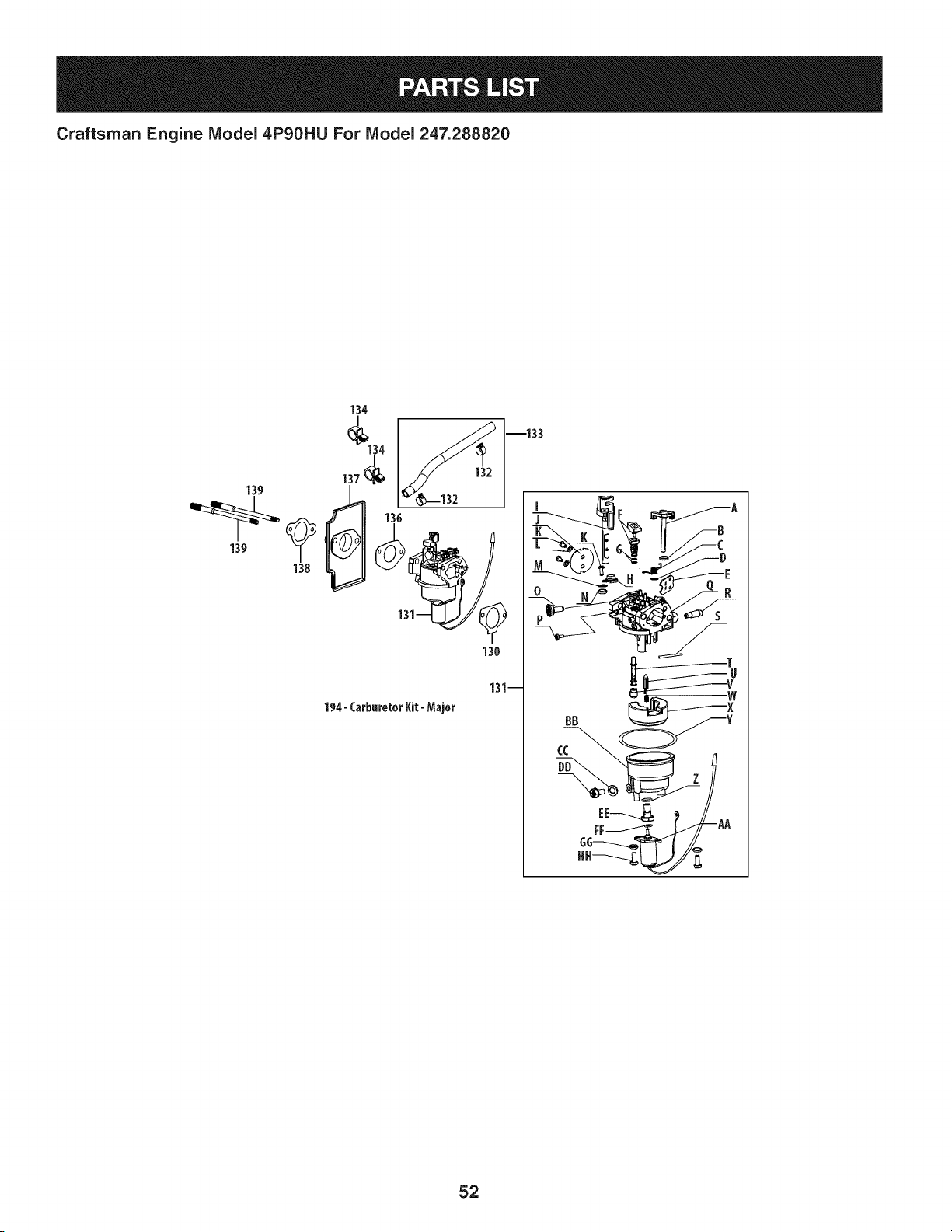
Craftsman Engine Model 4P9OHU For Model 247.288820
194- CarburetorKit-Major
131--
--133
52
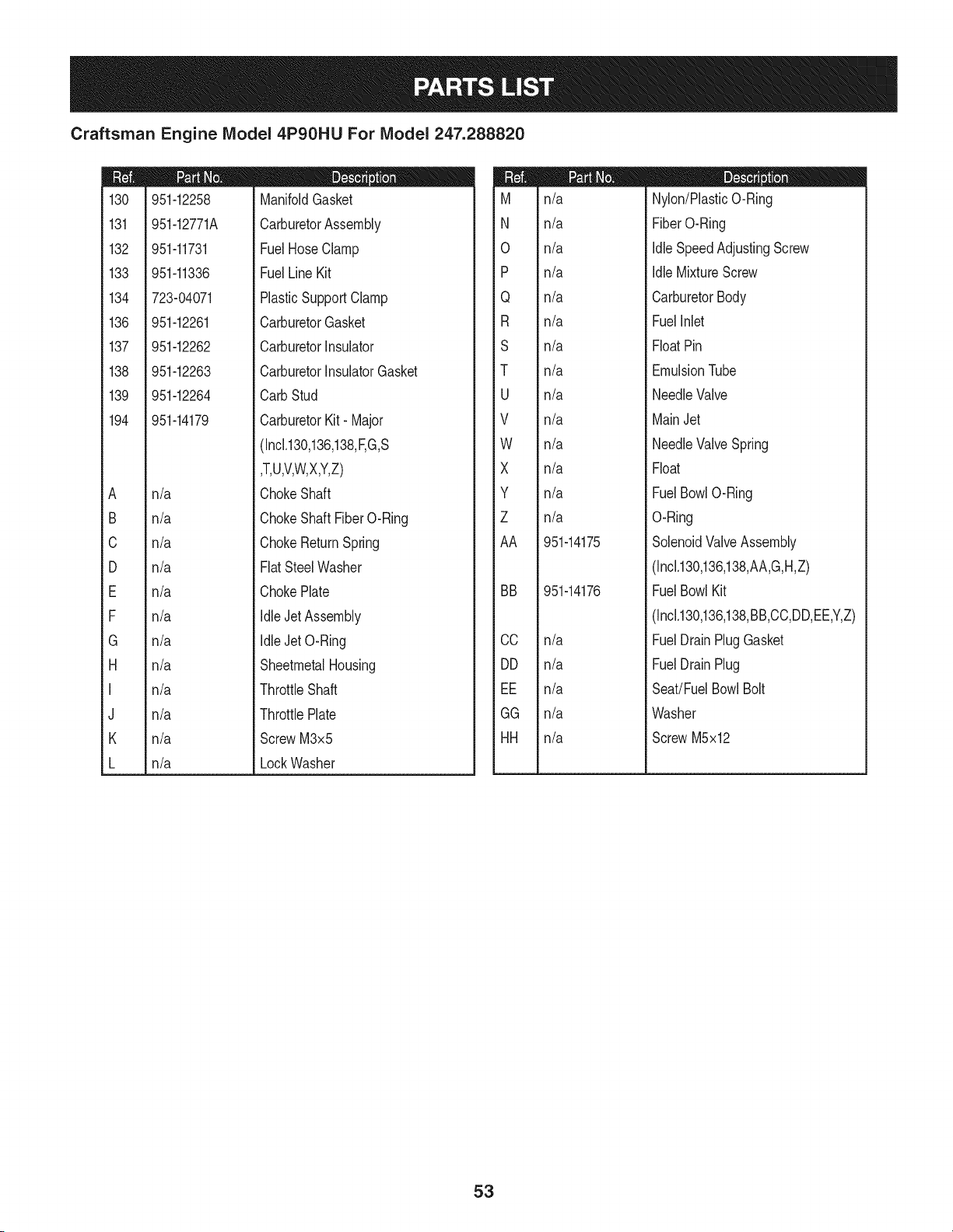
Craftsman Engine Model 4P90HU For Model 247.288820
m
130
131
132
133
134
136
137
138
139
194
A
B
C
D
E
F
G
H
I
J
K
L
951-12258
951-12771A
951-11731
951-11336
723-04071
951-12261
951-12262
951-12263
951-12264
951-14179
n/a
n/a
n/a
n/a
n/a
n/a
n/a
n/a
n/a
n/a
n/a
n/a
m = O O
ManifoldGasket
CarburetorAssembly
FuelHoseClamp
FuelLine Kit
PlasticSupportClamp
CarburetorGasket
CarburetorInsulator
CarburetorInsulatorGasket
CarbStud
CarburetorKit- Major
(Inck130,136,138,F,G,S
,T,U,V,W,X,Y,Z)
ChokeShaft
ChokeShaftFiberO-Ring
ChokeReturnSpring
FlatSteelWasher
ChokePlate
IdleJet Assembly
IdleJet O-Ring
SheetmetalHousing
ThrottleShaft
ThrottlePlate
ScrewM3x5
LockWasher
m
M
N
0
P
Q
R
S
T
U
V
W
X
Y
Z
AA
BB
CC
DD
EE
GG
HH
n/a
n/a
n/a
n/a
n/a
n/a
n/a
n/a
n/a
n/a
n/a
n/a
n/a
n/a
951-14175
951-14176
n/a
n/a
n/a
n/a
n/a
D = O O
Nylon/PlasticO-Ring
FiberO-Ring
IdleSpeedAdjustingScrew
IdleMixtureScrew
CarburetorBody
FuelInlet
FloatPin
EmulsionTube
NeedleValve
MainJet
NeedleValveSpring
Float
FuelBowlO-Ring
O-Ring
SolenoidValveAssembly
(IncM30,136,138,AA,G,H,Z)
FuelBowlKit
(IncM30,136,138,BB,CC,DD,EE,Y,Z)
FuelDrainPlugGasket
FuelDrainPlug
Seat!FuelBowlBolt
Washer
ScrewM5x12
53
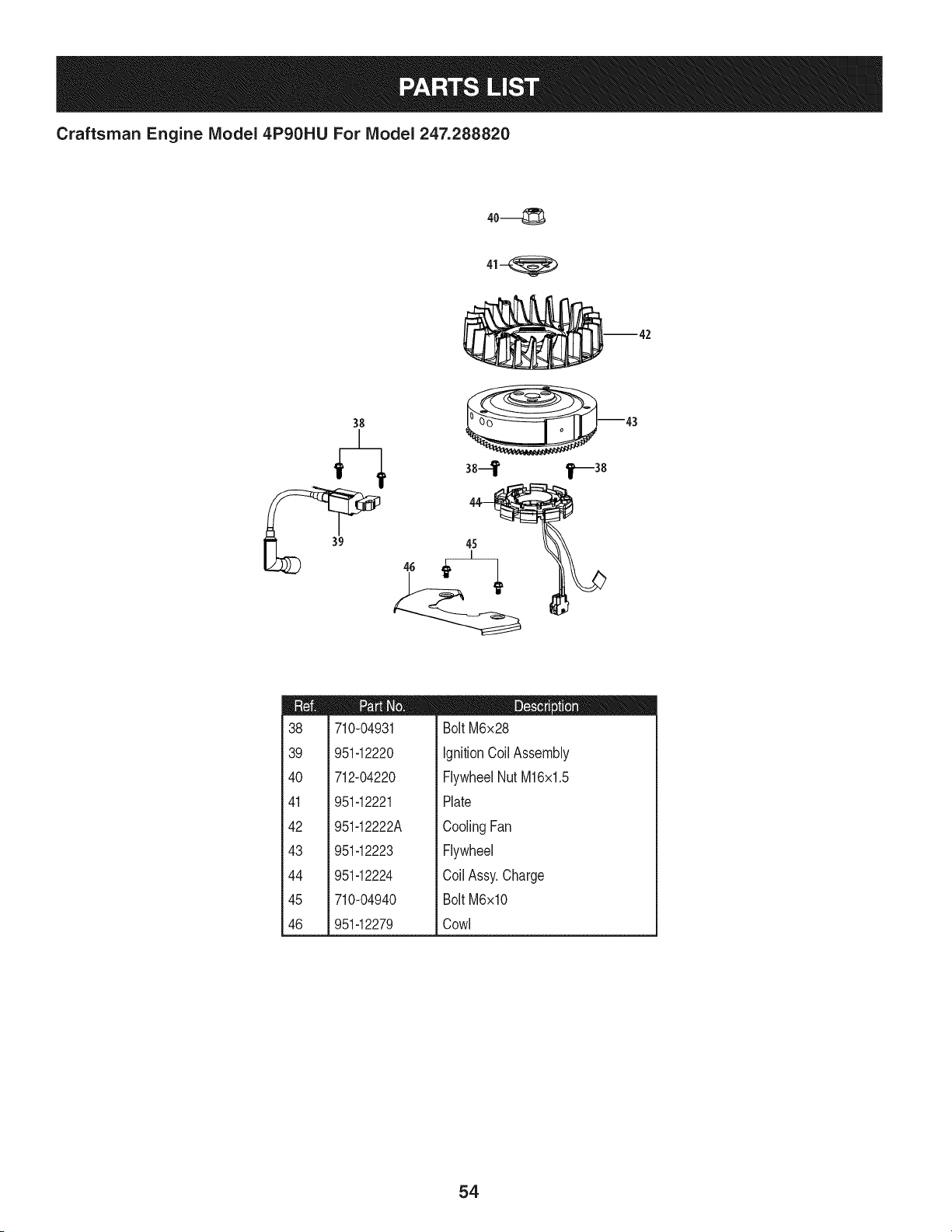
Craftsman Engine IViodel 4P90HU For IViodel 247.288820
m42
38
m
38
39
4O
41
42
43
44
45
46
710-04931
951-12220
712-04220
951-12221
951-12222A
951-12223
951-12224
710-04940
951-12279
D = O O
BoltM6x28
IgnitionCoil Assembly
FlywheelNutM16x1.5
Plate
CoolingFan
Flywheel
Coil Assy.Charge
BoltM6xlO
Cowl
54
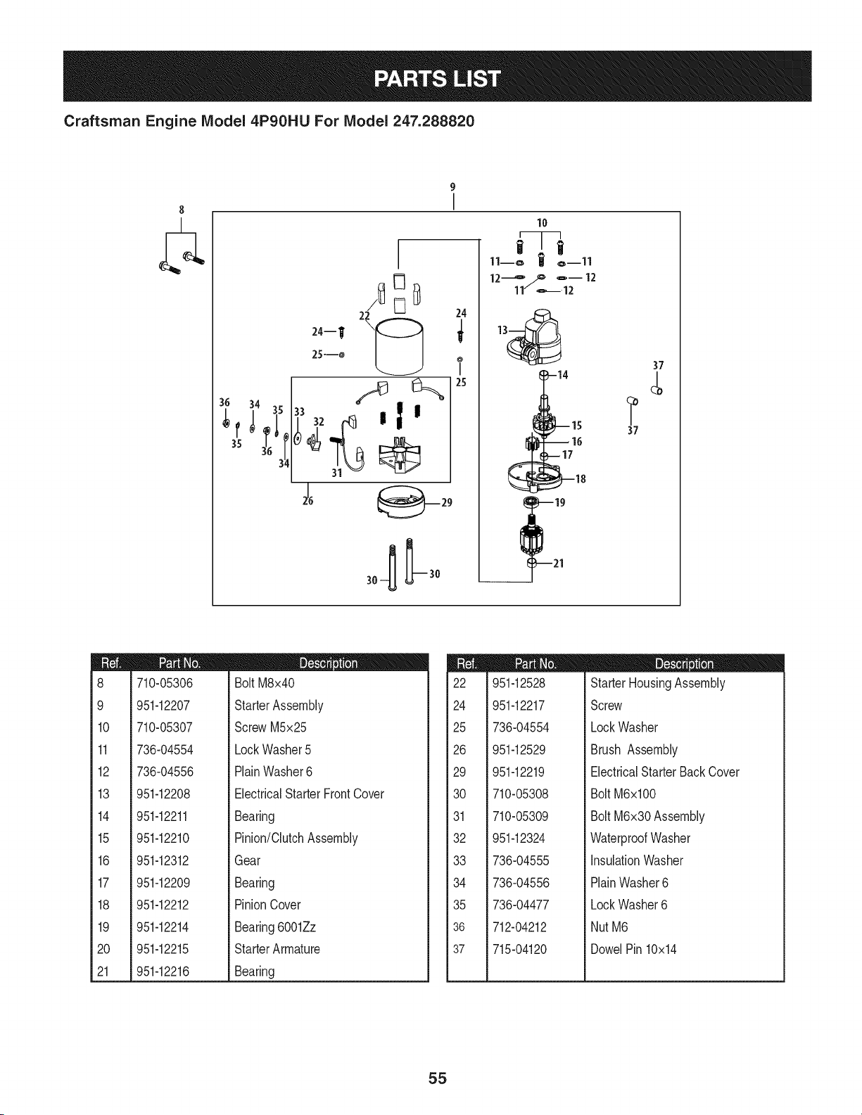
Craftsman Engine Model 4P90HU For Model 247.288820
8
9
I
24
25
10
11--o I o--ll
=-12
11 _12
i
_--17
37
?
37
m
8
9
10
11
12
13
14
15
16
17
18
19
2O
21
710-05306
951-12207
710-05307
736-04554
736-04556
I = O
BoltM8x40
StarterAssembly
ScrewM5x25
LockWasher5
PlainWasher6
951-12208
951-12211
951-12210
951-12312
951-12209
951-12212
951-12214
951-12215
951-12216
ElectricalStarterFrontCover
Bearing
Pinion/ClutchAssembly
Gear
Bearing
PinionCover
Bearing6001Zz
StarterArmature
Bearing
m
22
24
25
26
29
30
31
32
33
34
35
36
37
951-12528
951-12217
736-04554
951-12529
951-12219
710-05308
710-05309
951-12324
736-04555
736-04556
736-04477
712-04212
715-04120
m = O O
StarterHousingAssembly
Screw
LockWasher
Brush Assembly
ElectricalStarterBackCover
Bolt M6xl00
Bolt M6x30 Assembly
WaterproofWasher
InsulationWasher
PlainWasher6
LockWasher6
NutM6
DowelPin 10x14
55
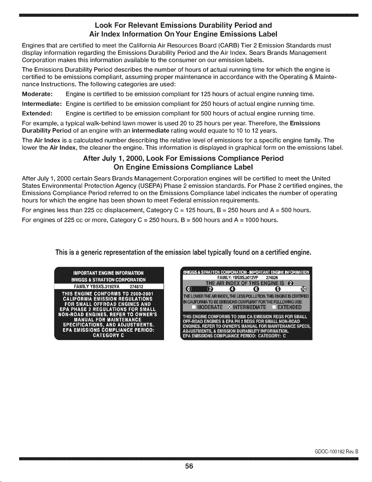
Look For Relevant Emissions Durability Period and
Air index information On Your Engine Emissions Label
Engines that are certified to meet the California Air Resources Board (CARB) Tier 2 Emission Standards must
display information regarding the Emissions Durability Period and the Air Index. Sears Brands Management
Corporation makes this information available to the consumer on our emission labels.
The Emissions Durability Period describes the number of hours of actual running time for which the engine is
certified to be emissions compliant, assuming proper maintenance in accordance with the Operating & Mainte-
nance Instructions. The following categories are used:
Moderate: Engine is certified to be emission compliant for 125 hours of actual engine running time.
Intermediate: Engine is certified to be emission compliant for 250 hours of actual engine running time.
Extended: Engine is certified to be emission compliant for 500 hours of actual engine running time.
For example, a typical walk-behind lawn mower is used 20 to 25 hours per year. Therefore, the Emissions
Durability Period of an engine with an intermediate rating would equate to 10 to 12 years.
The Air index is a calculated number describing the relative level of emissions for a specific engine family. The
lower the Air Index, the cleaner the engine. This information is displayed in graphical form on the emissions label.
After July 1,2000, Look For Emissions Compliance Period
On Engine Emissions Compliance Label
After July 1, 2000 certain Sears Brands Management Corporation engines will be certified to meet the United
States Environmental Protection Agency (USEPA) Phase 2 emission standards. For Phase 2 certified engines, the
Emissions Compliance Period referred to on the Emissions Compliance label indicates the number of operating
hours for which the engine has been shown to meet Federal emission requirements.
For engines less than 225 cc displacement, Category C = 125 hours, B = 250 hours and A = 500 hours.
For engines of 225 cc or more, Category C = 250 hours, B = 500 hours and A = 1000 hours.
This is a generic representation of the emission label typically found on a certified engine.
FAMILYYBSXS.3192VA 274812
GDOC-100182Rev.B
56
(Thispageapplicablein the U.S.A.and Canadaonly.)
Sears Brands Management Corporation (Sears), the California Air Resources Board (CARD)
and the United States Environmental Protection Agency (U.S. EPA)
Emission Control System Warranty Statement (Owner's Defect Warranty Rights and Obligations)
EMISSIONCONTROLWARRANTYCOVERAGEISAPPLICABLETO CERTI-
FIEDENGINESPURCHASEDIN CALIFORNIAIN 1995ANDTHEREAF-
TER,WHICHARE USEDINCALIFORNIA,ANDTOCERTIFIEDMODEL
California and United States Emission
The CaliforniaAir ResourcesBoard(CARD),U.S.EPAand Searsare pleased
to explainthe EmissionControlSystemWarrantyonyour modelyear2000and
latersmalloff-roadengine(SORE).In California,newsmall off-roadengines
mustbe designed,builtand equippedto meetthe State'sstringentanti-smog
standards.Elsewherein theUnitedStates, newnon-road,spark-ignition
enginescertifiedfor modelyear 1997and latermustmeetsimilarstandardsset
forth bythe U.S.EPA.Sears mustwarrantthe emissioncontrol systemon your
YEAR 1997AND LATERENGINESWHICHARE PURCHASEDAND USED
ELSEWHEREIN THE UNITEDSTATES(ANDAFTERJANUARY1,2001 IN
CANADA).
Control Defects Warranty Statement
enginefor theperiodsoftime listedbelow,providedtherehas been noabuse,
neglector impropermaintenanceof your smalloff-roadengine.Youremis-
sion controlsystemincludespartssuch as the carburetor,air cleaner,ignition
system,mufflerand catalyticconverter.Also includedmay be connectorsand
otheremissionrelatedassemblies.Wherea warrantableconditionexists,Sears
will repairyour smalloff-roadengineat no costto you includingdiagnosis,parts
and labor.
Sears Emission Control Defects Warranty Coverage
Smalloff-roadenginesarewarrantedrelativeto emissioncontrol partsdefects
fora periodof one year,subjectto provisionsset forth below.Ifany covered
Owner's Warranty
Asthe smalloff-roadengine owner,you are responsiblefor theperformanceof
therequiredmaintenancelistedin yourOperatingand MaintenanceInstruc-
tions.Searsrecommendsthatyou retain all yourreceiptscoveringmaintenance
on yoursmalloff-roadengine,but Sears cannotdenywarrantysolelyfor the
lackof receiptsorfor yourfailureto ensurethe performanceof all scheduled
maintenance.As the smalloff-roadengineowner,you shouldhoweverbe
awarethat Searsmaydenyyou warrantycoverageif your smalloff-roadengine
ora part hasfaileddueto abuse,neglect,impropermaintenanceor unap-
parton yourengineis defective,the part willbe repairedor replacedbySears.
Responsibilities
provedmodifications.Youare responsiblefor presentingyour smalloff-road
engineto an AuthorizedSearsServiceDealeras soonas a problemexists.The
undisputedwarrantyrepairsshouldbe completedina reasonableamountof
time,notto exceed30 days. Ifyou haveany questionsregardingyourwarranty
rightsand responsibilities,youshouldcontacta SearsService Representative
at 1-800-469-4663.The emissionwarrantyis a defectswarranty.Defectsare
judgedon normalengineperformance.The warrantyis notrelatedto an in-use
emissiontest.
Sears Emission Control Defects Warranty Provisions
ThefollowingarespecificprovisionsrelativetoyourEmissionControlDefectsWarrantyCoverage.Itisin additiontotheSearsenginewarrantyfornon-regulated
enginesfound in the Operatingand MaintenanceInstructions.
1. WarrantedParts
Coverageunderthis warrantyextendsonly to the parts listedbelow (the
emissioncontrolsystemsparts)to the extentthese partswere presenton
theengine purchased.
a. FuelMeteringSystem
• Cold start enrichmentsystem
• Carburetorand internalparts
• FuelPump
b. Air lnduction System
• Air cleaner
• Intakemanifold
c. IgnitionSystem
• Spark plug(s)
• Magnetoignitionsystem
d. CatalystSystem
• Catalyticconverter
• Exhaustmanifold
• Air injectionsystemor pulsevalve
e. MiscellaneousItemsUsedin AboveSystems
• Vacuum,temperature,position,timesensitivevalves
andswitches
• Connectorsandassemblies
2. Lengthof Coverage
Searswarrantsto the initialownerand eachsubsequentpurchaserthat
theWarrantedPartsshallbefree from defects in materialsandworkman-
shipwhich causedthefailure of the WarrantedPartsfor a periodof one
yearfrom the datethe engineis deliveredto a retailpurchaser.
3. NoCharge
Repairor replacementof anyWarrantedPartwill be performedat no
chargeto the owner,includingdiagnosticlabor whichleadsto the
determinationthata WarrantedPartis defective,ifthe diagnosticworkis
performedat an AuthorizedSearsServiceDealer.For emissionswarranty
servicecontact yournearestAuthorizedSears ServiceDealeras listed in
the "YellowPages"under"Engines,Gasoline,""GasolineEngines,""Lawn
Mowers,"or similar category.
4. Claimsand CoverageExclusions
Warrantyclaimsshall be filed in accordancewiththe provisionsof the
Sears EngineWarrantyPolicy.Warrantycoverageshall be excludedfor
failuresof WarrantedPartswhichare notoriginal Sears partsor because
of abuse,neglector impropermaintenanceas setforth inthe Sears
EngineWarrantyPolicy.Searsis notliableto coverfailuresof Warranted
Partscausedby the use of add-on, non-original,or modifiedparts.
5. Maintenance
Any WarrantedPart whichis notscheduledfor replacementas required
maintenanceor whichis scheduledonly for regularinspectionto the effect
of "repairor replaceas necessary"shallbe warrantedas to defectsfor the
warrantyperiod.Any WarrantedPartwhich is scheduledfor replacement
as requiredmaintenanceshallbe warrantedas to defectsonly forthe
periodof time upto the first scheduledreplacementfor that part. Any
replacementpart that is equivalentin performanceand durabilitymay
be usedin the performanceof any maintenanceor repairs.The owneris
responsibleforthe performanceof all requiredmaintenance,as definedin
the SearsOperatingand MaintenanceInstructions.
6. ConsequentialCoverage
Coveragehereundershallextendto thefailure of any engine components
caused bythe failureof any WarrantedPartstill underwarranty.
Inthe USAandCanada,a 24 hour hot line, 1-800-469-4663,has a menu of pre-recordedmessagesofferingyou enginemaintenanceinformation.
GDOC-100188Rev.B
57
FEDERALand/or CALIFORNIAEMISSIONCONTROLWARRANTYSTATEMENT
YOURWARRANTYRIGHTSANDOBLIGATIONS
MTD Consumer Group Inc, the United States Environmental Protection Agency (EPA), and, for those products certified for sale in the state of
California, the California Air Resources Board (CARB) are pleased to explain the emission (evaporative and/or exhaust) control system (ECS)
warranty on your outdoor 2006 and later small off-road spark-ignited engine and equipment (outdoor equipment engine) In California, new
outdoor equipment engines must be designed, built and equipped to meet the State's stringent anti-smog standards (in other states, 1997 and
later model year equipment must be designed, built, and equipped to meet the U.S. EPA small off-road, spark ignition engine regulations. MTD
Consumer Group Inc must warrant the ECSon your outdoor equipment engine for the period of time listed below provided there has been no
abuse, neglect or improper maintenance of outdoor equipment engine.
Your ECS may include parts such as the carburetor, fuel-injection system, the ignition system, catalytic converter, fuel tanks, fuel lines, fuel caps,
valves, canisters, filters, vapor hoses, clamps, connectors, and other associated emission-related components.
Where a warrantable condition exists, MTD Consumer Group Inc will repair your outdoor equipment engine at no cost to you including
diagnosis, parts and labor.
MANUFACTURER'SWARRANTYCOVERAGE:
This emission control system is warranted for two years. If any emission-related part on your outdoor equipment engine is defective, the part
will be repaired or replaced by MTD CONSUMER GROUP INC.
OWNER'SWARRANTYRESPONSIBILITIES:
As the outdoor equipment engine owner, you are responsible for performance of the required maintenance listed in your owner's manual. MTD
Consumer Group Inc recommends that you retain all receipts covering maintenance on your outdoor equipment engine, but MTD Consumer
Group Inc cannot deny warranty solely for the lack of receipts.
As the outdoor equipment engine owner, you should however be aware that MTD Consumer Group Inc may deny you warranty coverage if
your outdoor equipment engine or a part has failed due to abuse, neglect, or improper maintenance or unapproved modifications.
You are responsible for presenting your outdoor equipment engine to MTD Consumer Group Inc's distribution center or service center as soon
as the problem exists. The warranty repairs should be completed in a reasonable amount of time, not to exceed 30 days. If you have a question
regarding your warranty coverage, you should contact the MTD Consumer Group Inc Service Department at 1-800-800-7310 or via email at
http://su pport.mtd prod ucts.com
GENERALEMISSIONSWARRANTYCOVERAGE:
MTD Consumer Group Inc warrants to the ultimate purchaser and each subsequent purchaser that the outdoor equipment engine is: Designed,
built and equipped so as to conform with all applicable regulations; and free from defects in materials and workmanship that cause the failure
of a warranted part to be identical in all material respects to that part as described in MTD Consumer Group Inc's application for certification.
The warranty period begins on the date the outdoor equipment engine is delivered to an ultimate purchaser or first placed into service. The
warranty period is two years.
Subject to certain conditions and exclusions as stated below, the warranty on emission-related parts is as follows:
1. Any warranted part that is not scheduled for replacement as required maintenance in the written instructions supplied, is warranted for
the warranty period stated above. If the part fails during the period of warranty coverage, the part will be repaired or replaced by MTD
Consumer Group Inc according to subsection (4) below. Any such part repaired or replaced under warranty will be warranted for the
remainder of the period.
2. Any warranted part that is scheduled only for regular inspection in the written instructions supplied is warranted for the warranty period
stated above. Any such part repaired or replaced under warranty will be warranted for the remaining warranty period.
3. Any warranted part that is scheduled for replacement as required maintenance in the written instructions supplied is warranted for the
period of time before the first scheduled replacement date for that part. If the part fails before the first scheduled replacement, the part
will be repaired or replaced by MTD Consumer Group Inc according to subsection (4) below. Any such part repaired or replaced under
warranty will be warranted for the remainder of the period prior to the first scheduled replacement point for the part.
Repair or replacement of any warranted part under the warranty provisions herein must be performed at a warranty station at no charge
to the owner.
4.
5. Notwithstanding the provisions herein, warranty services or repairs will be provided at all of our distribution centers that are franchised to
service the subject engines or equipment.
6. The outdoor equipment engine owner will not be charged for diagnostic labor that is directly associated with diagnosis of a defective,
emission-related warranted part, provided that such diagnostic work is performed at a warranty station.
7. MTD Consumer Group Inc is liable for damages to other engine or equipment components proximately caused by a failure under
warranty of any warranted part.
8. Throughout the off-road engine and equipment warranty period stated above, MTD Consumer Group Inc will maintain a supply of
warranted parts sufficient to meet the expected demand for such parts.
9. Any replacement part may be used in the performance of any warranty maintenance or repairs and must be provided without charge to
the owner. Such use will not reduce the warranty obligations of MTD Consumer Group Inc.
10. Add-onormodifiedpartsthatarenotexemptedbytheAirResourcesBoardmaynotbeused.Theuseofanynon-exemptedadd-onor
modifiedpartsbytheultimatepurchaserwillbegroundsfordisallowingawarrantyclaims.MTDConsumerGroupIncwillnotbeliableto
warrantfailuresofwarrantedpartscausedbytheuseofanon-exemptedadd-onormodifiedpart.
WARRANTEDPARTS:
The repair or replacement of any warranted part otherwise eligible for warranty coverage may be excluded from such warranty coverage if
MTD Consumer Group Inc demonstrates that the outdoor equipment engine has been abused, neglected, or improperly maintained, and that
such abuse, neglect, or improper maintenance was the direct cause of the need for repair or replacement of the part. That notwithstanding,
any adjustment of a component that has a factory installed, and properly operating, adjustment limiting device is still eligible for warranty
coverage. Further, the coverage under this warranty extends only to parts that were present on the off-road engine and equipment purchased.
The following emission warranty parts are covered (if applicable):
1. Fuel Metering System
Cold start enrichment system (soft choke)
Carburetor and internal parts (or fuel injection system)
Fuel pump
Fuel tank
2. Air Induction System
Air cleaner
Intake manifold
3. Ignition System
Spark plug(s)
Magneto ignition system
4. Exhaust System
Catalytic converter
SAI (Reed valve)
5. Miscellaneous Items Used in Above System
Vacuum, temperature, position, time sensitive valves and switches
Connectors and assemblies
6. Evaporative Control
Fuel hose
Fuel hose clamps
Tethered fuel cap
Carbon canister
• Vapor lines
GDOCq00223Rev.A

Congratulations on making a smart purchase. Your new Craftsman® product is designed and
manufactured for years of dependable operation. But like all products, it may require repair
from time to time. That's when having a Repair Protection Agreement can save you money and
aggravation.
Here's what the Repair Protection Agreement* includes:
[] Expert service by our 10,000 professional repair specialists
[] Unlimited service and no charge for parts and labor on all covered repairs
[] Product replacement up to $1500 if your covered product can't be fixed
[] Discount of 25% from regular price of service and related installed parts not covered by the
agreement; also, 25% off regular price of preventive maintenance check
[] Fast help by phone - we call it Rapid Resolution - phone support from a Sears representative.
Think of us as a "talking owner's manual."
Once you purchase the Repair Protection Agreement, a simple phone call is all that it takes for you
to schedule service. You can call anytime day or night, or schedule a service appointment online.
The Repair Protection Agreement is a risk-free purchase. If you cancel for any reason during the
product warranty period, we will provide a full refund. Or, a prorated refund anytime after the
product warranty period expires. Purchase your Repair Protection Agreement today!
Some limitations and exclusions apply. For prices and additional information in the U.S.A.
call 1=800=827=6655.
*Coverage in Canada varies on some items. For full details call Sears Canada at 1=800=361=
6665.
Sears Installation Service
For Sears professional installation of home appliances, garage door openers, water heaters, and
other major home items, in the U.S.A. or Canada call 1=800=4=MY=HOME®.
60
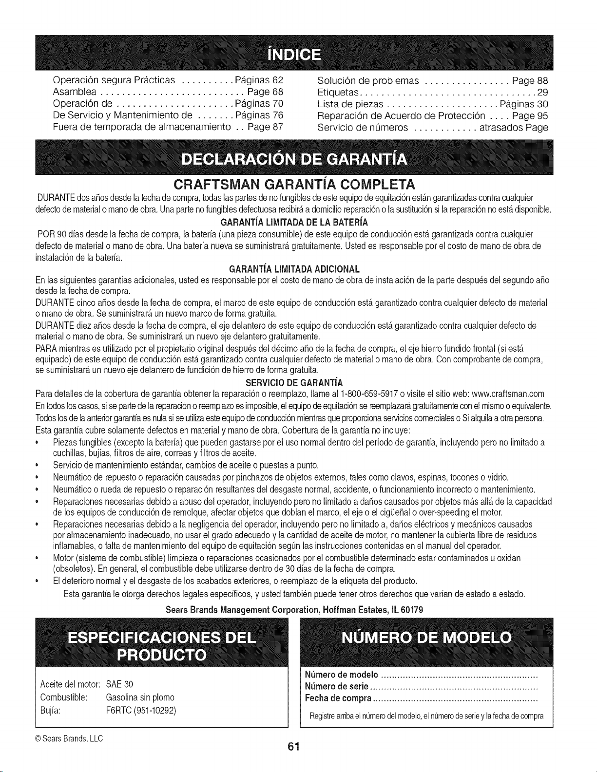
Operaci6n segura Pr,_cticas .......... Paginas 62
Asamblea ........................... Page 68
Operaci6n de ...................... Paginas 70
De Servicio y Mantenimiento de ....... Paginas 76
Fuera de temporada de almacenamiento .. Page 87
Soluci6n de problemas ................ Page 88
Etiquetas ................................. 29
Lista de piezas ..................... Paginas 30
Reparaci6n de Acuerdo de Protecci6n .... Page 95
Servicio de nOmeros ............ atrasados Page
CRAFTSMAN GARANTJA COMPLETA
DURANTEdosa_osdesdelafechadecornpra,todaslaspartesdenofungiblesdeesteequipode equitaci6nestangarantizadascontracualquier
defectodematerialo rnanodeobra.Unapartenofungiblesdefectuosarecibir_adornicilioreparaci6no lasustituci6nsi lareparaci6nnoest_ disponible.
GARANTJALIMITADADE LA BATERJA
POR90 dias desdelafecha decornpra,labateria(unapiezaconsurnible)de este equipode conducci6nesta garantizadacontracualquier
defectode materialo rnanode obra.Unabaterianuevase surninistrar_gratuitarnente.Ustedes responsableporelcostode rnanode obra de
instalaci6nde la bateria.
GARANTJALIMITADAADiCIONAL
Enlassiguientesgaranfiasadicionales,ustedes responsableporel costode rnanode obra de instalaci6ndela partedespu_sdelsegundoaSo
desdela fechadecornpra.
DURANTEcincoaSosdesdela fechade cornpra,el marcodeesteequipode conducci6nest&garantizadocontracualquierdefectode material
o rnanodeobra. Sesurninistrar&un nuevomarcode forrnagratuita.
DURANTEdiez aSosdesdelafechadecornpra,elejedelanterode esteequipode conducci6nest&garantizadocontracualquierdefectode
materialo rnanode obra.Se surninistrar&unnuevoeje delanterogratuitarnente.
PARArnientrases utilizadopor el propietariooriginaldespu_sdel d@irnoaSode lafecha de cornpra,el eje hierrofundidofrontal(si esta
equipado)de esteequipode conducci6nest&garantizadocontracualquierdefectodematerialo rnanode obra.Concornprobantedecornpra,
se surninistrar&un nuevoeje delanterode fundici6nde hierrode forrnagratuita.
SERViCIODE GARANTJA
Paradetallesde la coberturade garantiaobtenerla reparaci6no reernplazo,llarneal 1-800-659-5917o visiteel sitioweb: www.craftsrnan.corn
Entodosloscasos,sisepartedela reparaci6no reernplazoes irnposible,elequipodeequitaci6nsereernplazar&gratuitarnenteconel rnisrnooequivalente.
Todoslosde laanteriorgarantiaesnulasiseutilizaesteequipode conducci6nrnientrasqueproporcionaservicioscornercialeso Sialquilaaotrapersona.
Estagaranfiacubresolarnentedefectosen materialy rnanode obra.Coberturade lagaranfianoinduye:
• Piezasfungibles(exceptola bateria)que puedengastarseporel usonormaldentrodel periodode garantia,incluyendoperonolirnitadoa
cuchillas,bujias,filtrosde aire,correasy filtrosdeaceite.
• Serviciode rnantenirnientoestAndar,carnbiosde aceiteo puestasa punto.
NeurnAticode repuestoo reparaci6ncausadaspor pinchazosde objetosexternos,tales comoclavos,espinas,toconeso vidrio.
• Neurn&ticoo ruedade repuestoo reparaci6nresultantesdel desgastenormal,accidente,o funcionarnientoincorrectoo rnantenirniento.
• Reparacionesnecesariasdebidoa abusodeloperador,incluyendoperonolirnitadoa daSoscausadosporobjetosrn&sall&de la capacidad
de losequiposde conducci6nde rernolque,afectarobjetosque doblan el marco,eleje o el cig(JeSalo over-speedingel motor.
• Reparacionesnecesariasdebidoa la negligenciadeloperador,incluyendoperono lirnitadoa, daSosel@tricosy rnecanicoscausados
poralrnacenarnientoinadecuado,no usarel gradoadecuadoy la cantidadde aceitede motor,no rnantenerlacubiertalibrede residuos
inflarnables,o falta de rnantenirnientodel equipode equitaci6nsegL_nlasinstruccionescontenidasen el manualdel operador.
Motor(sistemadecombustible)limpiezao reparacionesocasionadosporel combustibledeterrninadoestarcontarninadosuoxidan
(obsoletos).Engeneral,el combustibledebe utilizarsedentrode 30 dias dela fechade cornpra.
• Eldeterioronormaly el desgastede losacabadosexteriores,o reernplazode laetiquetadel producto.
Estagarantiale otorgaderechoslegalesespecificos,y ustedtambi_npuedetenerotrosderechosquevariandeestadoa estado.
Sears Brands ManagementCot _oration, Hoffman Estates, iL 60179
NSrnerode rnodelo ..........................................................
Aceitedel motor: SAE30 N_mero de serie ..............................................................
Combustible: Gasolinasinplorno Fechade compra.............................................................
Bujia: F6RTC(951-10292) RegistrearribaelnQmerodelmodelo,elnQmerodeserieylafechadecompra
©SearsBrands,LLC
61
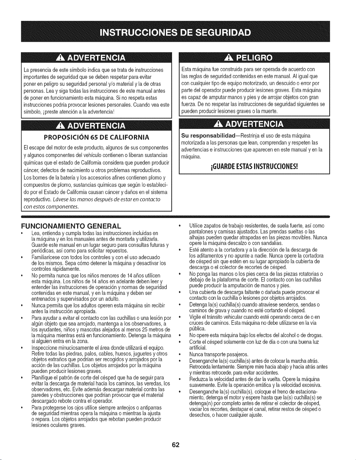
Lapresenciadeestesirnboloindicaquesetratadeinstrucciones
irnportantesdeseguridadquesedebenrespetarparaevitar
ponerenpeligrosuseguridadpersonaly/omaterialyladeotras
personas.Leaysigatodaslasinstruccionesdeestemanualantes
deponerenfuncionarnientoestarn_.quina.Sinorespetaestas
instruccionespodriaprovocarlesionespersonales.Cuandoveaeste
sirnbolo,ipresteatenci6nalaadvertencia!
PROPOSICI6N 65 DE CALIFORNIA
Elescapedel motorde esteproducto,algunosde sus cornponentes
y algunoscornponentesdel vehiculocontieneno liberansustancias
quirnicasqueel estadode Californiaconsideraque puedenproducir
c_.ncer,defectosde nacirnientouotros problernasreproductivos.
Losbornesdela bateriay losaccesoriosdines contienenplornoy
cornpuestosde plorno,sustanciasquirnicasquesegQnIoestableci-
do pot el EstadodeCaliforniacausanc_.ncery da_osen el sisterna
reproductivo.Ldveselas manos despu_sde estaren contadto
con estoscomponentes.
Estarn_.quinarueconstruidaparaseroperadade acuerdocon
las reglasde seguridadcontenidasen este manual.AI igualque
concualquiertipo deequipornotorizado,undescuidoo errorpor
partedel operadorpuedeproducirlesionesgraves.Estarn_.quina
es capazde arnputarrnanosy piesy dearrojarobjetoscon gran
fuerza.De norespetarlas instruccionesde seguridadsiguientesse
puedenproducirlesionesgraveso la rnuerte.
Su responsabilidad--Restrinja el usode estarn_.quina
rnotorizadaalas personasque lean,cornprendany respetenlas
advertenciase instruccionesque aparecenen este manualyen la
rn_.quina.
iGUARI)E ESTASINSTRUCCIONES!
FUNCIONAMIENTO GENERAL
• Lea,entienday curnplatodaslas instruccionesincluidasen
la rn_.quinayen los rnanualesantesde rnontarlay utilizarla.
Guardeestemanualen un lugarseguroparaconsultasfuturasy
peri6dicas,asi cornoparasolicitarrepuestos.
• Farniliaricesecontodoslos controlesy con el usoadecuado
de losrnisrnos.Sepa c6rnodetenerlarn_.quinay desactivarlos
controlesr_.pidarnente.
• No perrnitanuncaque losni_os rnenoresde 14a_osutilicen
estarn_.quina.Los ni_osde 14a_osen adelantedebenleery
entenderlas instruccionesde operaci6ny norrnasdeseguridad
contenidasen estemanual,yen la rn_.quinay debenser
entrenadosy supervisadospor un adulto.
• Nuncaperrnitaquelos adultosoperenesta rn_.quinasin recibir
antesla instrucci6napropiada.
• Paraayudara evitarel contactocon las cuchillaso una lesi6npor
algQnobjetoqueseaarrojado,rnantengaa los observadores,a
los ayudantes,ni_osy rnascotasalejadosal rnenos25 metrosde
la rn_.quinarnientrasest,.en funcionarniento.Detengala rn_.quina
si alguienentraen la zona.
• Inspeccionerninuciosarnenteel Areadondeutilizar_,el equipo.
Retiretodaslas piedras,palos,cables,huesos,juguetesy otros
objetosextra_osque podrianser recogidosy arrojadospor la
acci6nde lascuchillas.Losobjetosarrojadospor la rn_.quina
puedenproducirlesionesgraves.
• Planifiqueel patr6nde cortedelc_spedque hadeseguirpara
evitarla descargade materialhacialoscarninos,lasveredas,los
observadores,etc. Eviteadern_.sdescargarmaterialcontralas
paredesy obstruccionesque podrianprovocarque el material
descargadorebotecontrael operador.
• Paraprotegerselos ojosutilicesiernpreanteojoso antiparras
de seguridadrnientrasoperalarn_.quinao rnientrasla ajusta
o repara.Losobjetosarrojadosque rebotanpuedenproducir
lesionesocularesgraves.
• Utilicezapatosde trabajoresistentes,de suelafuerte,asi corno
pantalonesy carnisasajustados.Lasprendassueltaso las
alhajaspuedenquedaratrapadasen las piezasrnovibles.Nunca
operela rn_.quinadescalzoo con sandalias.
• Est_atentoa lacortadoray a la direcci6ndela descargade
los aditarnentosy noapuntea nadie.Nuncaoperela cortadora
de cespedsin queest_nen su lugarapropiadola cubiertade
descargao elcolectorde recortesde c_sped.
• Noponga las rnanoso los piescercade las piezasrotatoriaso
debajode la plataforrnadecorte. Elcontactocon las cuchillas
puedeproducirla arnputaci6nde rnanosy pies.
• Unacubiertadedescargafaltanteoda_adapuedeprovocarel
contactoconla cuchillao lesionespor objetosarrojados.
• Detengala(s)cuchilla(s)cuandoatraviesesenderos,sendaso
carninosdegravay cuandono est_cortandoel c_sped.
• Vigileeltr_.nsitovehicularcuandoest_operandocercadeoen
crucesde carninos.Estarn_.quinanodebeutilizarseen la via
pQblica.
• Noopereesta rn_.quinabajolosefectosdel alcoholo de drogas.
• Corteel cespedsolarnentecon luzde dia o con unabuenaluz
artificial.
• Nuncatransportepasajeros.
• Desenganchela(s)cuchilla(s)antesdecolocarlarnarchaatr_.s.
Retrocedalentarnente.Siernpremirehaciaabajoy haciaatr_.santes
y rnientrasretrocede,paraevitaraccidentes.
• Reduzcalavelocidadantesdedar la vuelta.Operela rn_.quina
suavernente.Evitelaoperaci6nerr_.ticay la velocidadexcesiva.
• Desenganchela(s)cuchilla(s),coloqueel frenodeestaciona-
rniento,detengael motory esperehastaque la(s)cuchilla(s)se
detenga(n)porcornpletoantesderetirarel colectorde c_sped,
vaciarlos recortes,destaparel canal,retirarrestosde cespedo
desechos,o hacercualquierajuste.
62
• Nuncadejelarn_.quinaen funcionarnientosinvigilancia.Apague
siernprelascuchillas,coloqueel frenodernano,detengael motory
retirela Ilaveantesdebajarsedelvehiculo.
• Tengasurnocuidadoal cargaro descargarla rn_.quinaen un
rernolqueocarni6n.Estaunidadno debeconducirseenascensoo
descensoderarnpas,porquepodrialadearsey provocarlesiones
personalesgraves.Enlas rarnpasla rn_.quinasedebeernpujar
rnanualrnenteparacargarlao descargarlacorrectarnente.
• Elsilenciadory el motorse calientany puedencausarquernaduras.
No lostoque.
• Reviseelespaciolibreporencirnade la cabezaantesde conducir
bajolas rarnasbajasde _.rboles,cables,cerrarnientosde puertas,
etc.en loscualeseloperadorpodriaatorarseo seternpujadofuera
dela rn_.quina,Ioque podriaresultaren lesionesgraves.
• Desenganchetodoslosernbraguesde losaccesoriosy presione
totalrnenteel pedaldelfrenoantesdeintentararrancarel motor.
• Larn_.quinaest,. dise_adaparacortarc_spedresidencialnormal,
conuna alturano mayora 10".Nointentecortarcespeddernasiado
crecido,seco(porej.,pastura)nipilasde hojassecas.Elc_sped
y las hojassecaspuedenentraren contactocon el escapedel
motory/o acurnularseenlaplataforrnade lacortadorade cesped,
convirti_ndoseen unpeligrodeincendio
• Utilicesolarnenteaccesoriosy aditarnentosaprobadosparaesta
rn_.quinapor el fabricantede la rnisrna.Lea,cornprenday siga
todaslasinstruccionesproporcionadascon losaccesorioso
aditarnentosaprobados.Paraobtenerunalistadelos accesorios
aprobadosy losarchivosadjuntos,Ilarne1-800-659-5917.
• Losdatosestadfsticosrnuestranque losoperadoresde 60 a_os
y rnayoresseven involucradosen un altoporcentajede lesiones
relacionadascontractorescorta cesped.Estosoperadoresdeben
evaluarsu capacidadparaoperareltractorcortac_spedenforrna
suficienternenteseguraparaprotegersea ellosrnisrnosy a los
dern_.scontralesionesgraves.
Si se presentansituacionesquenoest_.nprevistasen este
manualsea cuidadosoy use el sentidocornOn.
FUNCIONAMIENTO EN PENDIENTES
Las pendientesson un factorirnportanterelacionadoconaccidentes
porderrapey vuelcosquepuedenproducirlesionesgravese incluso
la rnuerte.Laoperaci6nen pendientesrequiemmayorprecauci6n.
Si nopuederetrocederen la pendienteo si no se sienteseguro,no
realiceningunaoperaci6nde corte.
Parasuseguridad,use el indicadorde pendientesque se incluye
cornoparte de estemanualpararnedirla pendienteantesde operarla
rn_.quinaenunazonainclinada.Si la pendientees mayorde 15grados
segOnelrnedidor,noopereestarn_.quinaenese sector,puespodria
causarlesionesgraves.
HagaIo siguiente:
• Podehaciaarribay abajode laspendientes,node forrnatrans-
versal.Tengacuidadocuandocarnbiededirecci6nal operaren
pendiente.
• Est_atentoa loshoyos,surcos,baches,rocas,u otrosobjetos
ocultos.Elterrenodesniveladopuedevoltearla rn_.quina.Elcesped
altopuedeocultarobst_.culos.
Vayaa bajavelocidad.ElijaunavelocidadIosuficienternentebaja,
de rnodoquenotengaque detenerseo hacercarnbiosrnientras
est,.sobrela pendiente.Losneurn_.ticospodrianperdertracci6n
sobrelaspendientesaQncuandolos frenosfuncionaranapro-
piadarnente.Siernprernantengala rn_.quinaen carnbiornientras
desciendelaspendientes,parapoderfrenarconel motor.
• Sigalas recornendacionesdel fabricanteparalos pesoso contra-
pesosdelas ruedas,pararnejorarla estabilidaddela rn_.quina.
• Tengaespecialcuidadocon loscolectoresdec_spedu otros
aditarnentos.Losrnisrnospuedenrnodificarlaestabilidadde la
rn_.quina.
• Hagaquetodoslosrnovirnientosenlas pendientesseanlentosy
graduales.No carnbierepentinarnentelavelocidadniladirecci6n.
Unfrenadoo carnbiodevelocidadrepentinospuedencausarque
el frentede larn_.quinase levantey d_ unavolteretahaciaatr_.s,Io
quepodriaproducirlesionesgraves.
• Evitearrancaro detenerseenunapendiente.Silosneurn_.ticos
pierdenlatracci6n,desenganchelascuchillasy descienda
lentarnentelapendiente.
No hagaIo siguiente:
• Nogiresobrelaspendientesa rnenosque seanecesario.Sies
posible,girelentarnentey gradualrnenteduranteeldescenso.
• Nocorteel cespedcercadepozos,hundirnientosoterraplenes.La
cortadoradec_spedpuedevolcarserepentinarnentesiunade las
ruedasest,.sobreel hordede unacantilado,zanjao siunhordese
desrnorona.
• Nointenteestabilizarla rn_.quinaponiendoelpieenel suelo.
• Noutiliceuncolectordec_spedenpendientesernpinadas.
• Nopodeel cespedhOrnedo.Unarnenortracci6npodriacausar
derrapes.
• Noparadescender.Elexcesodevelocidadpuedehacerqueel
operadorpierdael controlde la rn_.quina,ocasionandolesiones
graveseinclusolarnuerte.
• Norernolquecargaspesadasdetr_.sdelosaditarnentos(carritode
basuracargado,podadorade rodillos,etc)en pendientesrnayores
de5 grados.Cuandosedesplazapendienteabajo,el pesoadicional
tiendeaernpujarel tractory puedehacerquesepierdaelcontrol
delrnisrno(potejernplo,eltractorse puedeacelerar,sereducela
capacidadparafrenary rnaniobrar,losaccesoriospuedenplegarse
cornouncortaplurnasy hacerqueel tractorvuelque).
NINOS
Puedenocurriraccidentestr_.gicossi el operadorno est,. atentoa la
presenciade ni_os.PorIo general,los ni_osse sientenatraidospor
estetipo dern_.quinasy su funcionarniento.Noentiendenlos riesgos
nilos peligros.Nuncaasurnaquelos ni_osperrnanecer_.nen el rnisrno
lugardondelos vio por Qltirnavez.
Mantengaalosni_osfueradel_reade trabajoy bajoestricta
vigilanciadeunadultoresponsableadern_.sdel propiooperador.
Est_alertay apaguelarn_.quinasiunni_oingresaal_.rea.
Antesy rnientrasest,.retrocediendo,mirehaciaatr_.sy cuideque no
hayani_os.
Nuncatransporteni_os,aQnconlacuchillaapagada.Podriancaerse
y resultarseverarnenteheridoso interferirconlaoperaci6nsegurade
lam_.quina.
• Tengaextrernaprecauci6ncuandoseaproxirnea esquinasciegas,
portales,arbustos,_.rbolesuotrosobjetosquepuedanirnpedirlever
a unni_oquesecruceen el recorridodelarn_.quina.
63
• Paraevitaraccidentesal operaren rnarchaatr_.s,siernpredesengan-
chelascuchillasantesde colocarrnarchaatr_.s.Siest,.instalado,
el"ModoPrecauci6nMarchaAtr_.s"(hojasdeoperarlarn_.quina,
rnientrasquelos paseosala inversa)no debeutilizarsecuandohay
ni_osuotraspersonaspresentes.
• Mantengaa losni_osalejadosdelosrnotoresenrnarchao calientes.
Puedensufrirquernadurasconun silenciadorcaliente.
• RetirelaIlavecuandodejelarn_.quinasinvigilancia,evitequeuna
personasinautorizaci6nla rnaneje.
No perrnitanuncaque losni_os rnenoresde 14a_osutilicenesta
rn_.quina.Los ni_osde 14a_osen adelantedebenleer y entenderlas
instruccionesdeoperaci6ny norrnasde seguridadcontenidasen este
manual,y enla rn_.quinay debenserentrenadosy supervisadospor
unadulto.
REIVIOLQUE
• Rernolque_nicarnenteconunarn_.quinaquecuenteconun
enganchediseSadopararernolcar.Noacopleequiporernolcado
exceptoenelpuntodeenganche.
• Sigalasrecornendacionesdel fabricanteenIoque respectaalos
lirnitesdepesode losequiposa rernolcary al rernolqueen pendien-
tes.
• Nuncaperrnitalapresenciade niSosu otraspersonasdentroo sobre
losequiposrernolcados.
• Enlaspendientes,elpesodel equiporernolcadopuedecausar
p_rdidadetracci6ny perdidadecontrolde la rn_.quina.
• Siernpreuseextralaprecauci6nrernolcandoconunarn_.quina
capazdehacervueltasapretadas(p.ejpaseo"devueltacero"-enel
cortac_sped).Hagaarnpliasvueltasparaevitaralgato-knifing.
• Despl_.ceselentarnentey dejedistanciaadicionalparafrenado.
• Noparadescender.
SERVIClO
Manejo seguro de la gasolina
Paraevitarlesionespersonaleso daSosrnaterialessea surnarnente
cuidadosoal rnanipularla gasolina.Lagasolinaes surnarnente
inflarnabley sus vaporespuedencausarexplosiones.Sepuede
lesionargravernentesi derrarnagasolinasobreustedo sobrela ropa,
ya que _stase puedeincendiar. L_.vesela piely c_.rnbiesede ropade
inrnediato.
• Utilices61olos recipientesparagasolinaautorizados.
• NuncaIlenelos recipientesen el interiordeunvehiculoo carni6n
ocaja de rernolquecon recubrirnientopl_.stico.Coloquesiernpre
los recipientesen el piso y lejosdel vehiculoantes de realizarla
carga.
• Cuandosea factible,retireel equipoa gasolinadel carni6no
rernolquey II_neloen el suelo.Si esto no es posible,Ileneel
equipoen unrernolqueconun contenedorport_.til,envezde
hacerlocon una boquilladispensadoradegasolina.
• Mantengala boquillade Ilenadoencontactocon el horde del
dep6sitode combustibleo con la aberturadel recipienteentodo
rnornento,hastaterrninarla carga. No utiliceundispositivode
boquilladeapertura/cierre.
Apaguetodosloscigarrillos,cigarros,pipasy otrasfuentesde
cornbusti6n.
• Nuncacarguecombustibleenla rn_.quinaen un espaciocerrado.
• Nuncasaquela tapadel combustibleni agreguecombustible
rnientrasel motorest,.calienteo enrnarcha.Dejequeel motor
se enfrie porIo rnenosdos rninutosantes de volvera cargar
combustible.
• NuncaIleneen excesoel dep6sitode combustible.Lleneel
tanqueno rn_.sde 1/2pulgadapordebajode labasedelcuello
del tap6nde carga, paradejar espacioparalaexpansi6ndel
combustible.
• Vuelvaa colocarlatapade la gasolinay ajQstelabien.
• Lirnpieel combustibleque sehayaderrarnadosobreel motory el
equipo.Trasladelarn_.quinaa otrazona. Espere5 rninutosantes
de encenderel motor.
• Parareducirel riesgode incendio,rnantengala rn_.quinalirnpia
de pasto,hojasy de acurnulaci6nde otrosresiduos.Lirnpielos
derrarnesde aceiteo combustibley saquetodoslos residuos
ernbebidosde combustible.
• Nuncaguardela rn_.quinao el recipientede combustibleen un
espaciocerradodondehayafuego,chispaso luz piloto,corno
por ejernplodecalentadoresdeagua,calefactoresde arnbientes,
hornos,secadoresde ropau otrosaparatosa gas.
• Dejeque la rn_.quinase enfriecinco rninutospor Io rnenosantes
de guardarla.
Servicio general
• Nuncaenciendaelmotorenespacioscerradoso en unazona
con pocaventilaci6n.El escapedel motorcontienernon6xidode
carbono,ungas inodoroy letal.
• Antesde lirnpiar,repararo inspeccionarla rn_.quina,cornpruebe
que la(s)cuchilla(s)y todaslas partesen rnovirnientose hayan
detenido.Desconecteelcablede la bujfay p6ngalohaciendo
rnasacontrael motorpara evitarque se enciendaaccidental-
rnente.
• Reviseperi6dicarnenteparaasegurarsequelascuchillasse
detenganpot cornpletoenaproxirnadarnentecinco(5)segundos
despu_sdeaccionarel controlde desenganchede la(s)
cuchilla(s).Si lascuchillasnose detienendentrode este lapso
de tiernpo,su unidaddeber_,ser reparadapor sudistribuidorde
servicioautorizadoMTD.
• Reviseconfrecuenciael funcionarnientodel sisternade frenos
ya que est,.sujetoa desgasteporla operaci6nnormal.Ajustey
efectQernantenirnientosegQnse requiera.
64
• Reviselos pernosdernontajede la(s)cuchilla(s)y delmotor a
intervalosfrecuentesparaverificarque est_n bienapretados.
Adern_.s,inspeccionevisualrnentela(s) cuchilla(s)enbuscade
da_os(por ejernplo,desgasteexcesivo,abolladuras,rajaduras,
etc.). Reernplacela(s) cuchilla(s)Qnicarnenteconlas cuchillas
defabricantesdeequiposoriginales(O.E.M.)listadasen este
manual.Elusode piezasqueno curnplencon lasespecifi-
cacionesdelequipooriginal podriatenercornoresultadoun
rendirnientoincorrectoy adern_.sponeren riesgola seguridad.
Lascuchillasdelas podadorassonrnuyafiladas.Envuelvala
cuchillao utiliceguantesy extremelas precaucionescuando
efect_ernantenirniento.
• Mantengatodoslospernos,tuercasy tornillosbienajustados
paraasegurarsede que la rn_.quinaseencuentraen condiciones
segurasde operaci6n.
• Nuncaaltereel sisternade enclavarnientode seguridadni
otrosmecanisrnosde seguridad.Controleperi6dicarnenteque
funcionencorrectarnente.
• Despu_sdegolpearcon algQnobjetoextra_o,detengael motor,
desconecteelcablede la bujfay conecteel motora rnasa.
Inspeccionerninuciosarnentela rn_.quinaparaver si est,. da_ada.
Repareel da_oantesde arrancary utilizarla rn_.quina.
• Nuncatratedehacerajusteso reparacionesa la rn_.quina
rnientrasel motorest,.enrnarcha.
• Loscornponentesdel colectordecespedy la cubiertade
descarga,est_.nsujetosa desgastey da_osque podriandejar
expuestaspartesen rnovirnientoo perrnitirquesearrojen objetos.
Paraprotegersu seguridad,verifiquefrecuenternentetodos los
cornponentesy reernpl_.celosinrnediatarnentes61ocon piezasde
los fabricantesdel equipooriginal,listadosen este manual.El uso
depiezasque no curnplenconlas especificacionesdel equipo
originalpodriatenercornoresultadounrendirnientoincorrectoy
adern_.sponeren riesgola seguridad.
• No carnbiela configuracidndel reguladordelmotorni Io opere
a sobrevelocidad.El reguladordel motorcontrolalavelocidad
rn_.xirnasegurade funcionarnientodelmotor.
• Mantengao reernplacelasetiquetasde seguridade instrucciones
segQnseanecesario.
• Respetelas norrnasreferentesa la disposici6ncorrectay las
reglarnentacionessobregasolina,aceite,etc. para protegerel
medicarnbiente.
• SegOnla Cornisidnde Seguridadde Productospara el Consurni-
dorde los EstadosUnidos(CPSC)y la Agenciade Proteccidn
Arnbientalde los EstadosUnidos(EPA),este productotiene una
vida Qtilmediade siete(7) a_os,6 270horasde funcionarniento.
AIfinalizarla vida [3tilmedia,adquieraunarn_.quinanuevao haga
inspeccionaranualrnente_staSearsporunou otrodistribuidorde
serviciosparacerciorarsedeque todos los sisternasrnec_.nicos
y de seguridadfuncionancorrectarnentey no tienenexcesivo
desgaste.Si noIo hace,puedenproducirseaccidentes,lesiones
o rnuerte.
NO MODIFIQUE EL MOTOR
Paraevitarlesionesgraveso larnuerte,no rnodifiqueel motorbajo
ningunacircunstancia.Si carnbiala configuracidndel reguladordel
motorelmotorpuededescontrolarsey operara velocidadesinsegu-
ras.Nuncacarnbielaconfiguracidndef_.bricadelreguladordel motor.
AVISO REFERIDO A EMISIONES
Losrnotoresque est&ncertificadosy curnplencon las regulaciones
de ernisionesfederalesEPAy de CaliforniaparaSORE(Equipos
peque_ostodoterreno)est_.ncertificadosparaoperarcon gasolina
cornOnsinplornoy puedenincluirlossiguientessisternasde control
de ernisiones:Modificacidndemotor(EM) y catalizadorde tresvias
(TWO)si est_.nequipadosde esa rnanera.
GUARDACHISPAS
Estarn&quinaest,.equipadacon unmotorde cornbusti6ninternay
nodebe serutilizadaeno cercade un terrenoagrestecubiertopor
bosque,rnalezaso hierbaexceptosi el sisternade escapedel motor
est,.equipadocon un arnortiguadordechispasquecurnplacon las
leyeslocalesoestatalescorrespondientes,encasode haberlas.
Sise utilizaun arnortiguadordechispasel operadorIo debernantener
en condicionesde usoadecuadas.Enel Estadode California las
rnedidasanteriorrnenternencionadassonexigidaspor ley (Arficulo
4442del Cddigode RecursosPOblicosde California).Es posible
queexistanleyessirnilaresenotrosestados.Lasleyesfederalesse
aplicanen territoriosfederales.
Puedeconseguirelarnortiguadorde chispasparael silenciadora
travesde sudistribuidorautorizadode rnotoreso poni_ndoseen
contactocon elcentrode servicioSears.
65
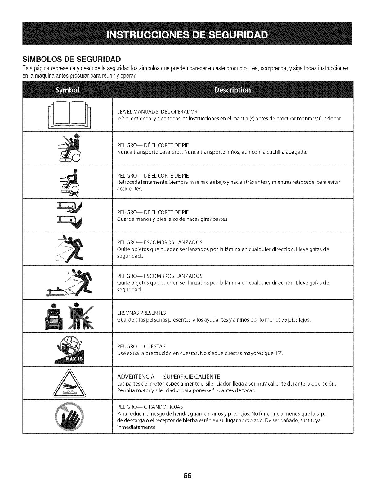
S[IVIBOLOS DE SEGURIDAD
Estap&ginarepresentay describelaseguridadlos simbolosquepuedenpareceren este producto.Lea,comprenda,y sigatodasinstrucciones
en lam_quinaantesprocurarpara reuniry operar.
i
i
®
J
®
,E,
AL
LEA EL MANUAL(S) DEL OPERADOR
leido, entienda, y siga todas las instrucciones en el manual(s) antes de procurar montar y funcionar
PELIGRO-- DE EL CORTE DE PIE
Nunca transporte pasajeros. Nunca transporte niffos, aun con la cuchilla apagada.
PELIGRO-- DE EL CORTE DE PIE
Retroceda lentamente. Siempre mire hacia abajo y hacia atr_is antes y mientras retrocede, para evitar
accidentes.
PELIGRO-- DE EL CORTE DE PIE
Guarde manos y pies lejos de hacer girar partes.
PELIGRO-- ESCOMBROS LANZADOS
Quite objetos que pueden set lanzados por la I_imina en cualquier direcci6n. Lleve gafas de
seguridad..
PELIGRO-- ESCOMBROS LANZADOS
Quite objetos que pueden set lanzados por la I_imina en cualquier direcci6n. Lleve gafas de
seguridad.
ERSONAS PRESENTES
Guarde alas personas presentes, a los ayudantes y a nihos pot Io menos 75 pies lejos.
PELIGRO-- CUESTAS
Use extra la precauci6n en cuestas. No siegue cuestas mayores que 15°.
ADVERTENCIA -- SUPERFICIE CALIENTE
Las partes del motor, especialmente el silenciador, Ilega a set muy caliente durante la operaci6n.
Permita motor y silenciador para ponerse frio antes de tocar.
PELIGRO-- GIRANDO HOJAS
Para reducir el riesgo de herida, guarde manos y pies lejos. No funcione a menos que la tapa
de descarga o el receptor de hierba est6n en su lugar apropiado. De set dahado, sustituya
inmediatamente.
66
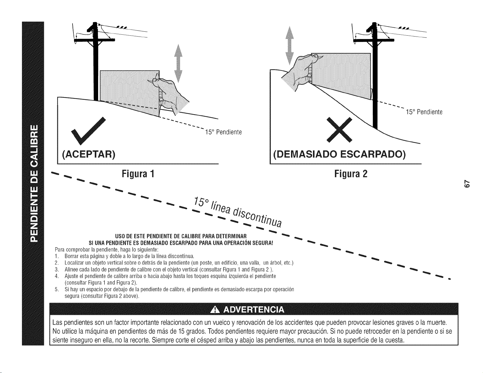
(ACEPTAR)
15° Pendiente
15° Pendiente
X
(DElVlASlADO ESCARPADO)
FiguraI Figura2
15°/fn
US0 DE ESTEPENDIENTEDECALIBREPARADETERMINAR
SI UNA PENDIENTEES DEMASIADOESCARPADOPARA UNA OPERACIONSEGURA!
Para comprobar la pendiente, haga Io siguiente:
1. Borrar esta p@ina y doble a Io largo de la lineadiscontinua.
2. Localizar un objeto vertical sobre o detr_.sde la pendiente (un poste, un edificio, una valla, un _.rbol,etc.)
3. Alinee cada lado de pendiente de calibre con el objeto vertical (consultar Figura 1 and Figura 2 ).
4. Ajuste el pendientede calibre arriba o hacia abajo hasta los toques esquina izquierda el pendiente
(consultar Figura 1 and Figura 2).
5. Si hay un espacio pot debajo de la pendiente de calibre, el pendientees demasiado escarpa pot operaciCn
segura (consultar Figura 2 above).
Las pendientesson un factor importante relacionadocon un vuelco y renovaciCnde los accidentes que pueden provocar lesiones graves o la muerte.
No utilice la ma.quinaen pendientes de mas de 15grados. Todos pendientes requiere mayor precauciCn.Si no puede retrocederen la pendiente o si se
siente inseguro en ella, no la recorte. Siempre corte el cesped arriba y abajo laspendientes, nunca en toda la superficie de la cuesta.
¢0
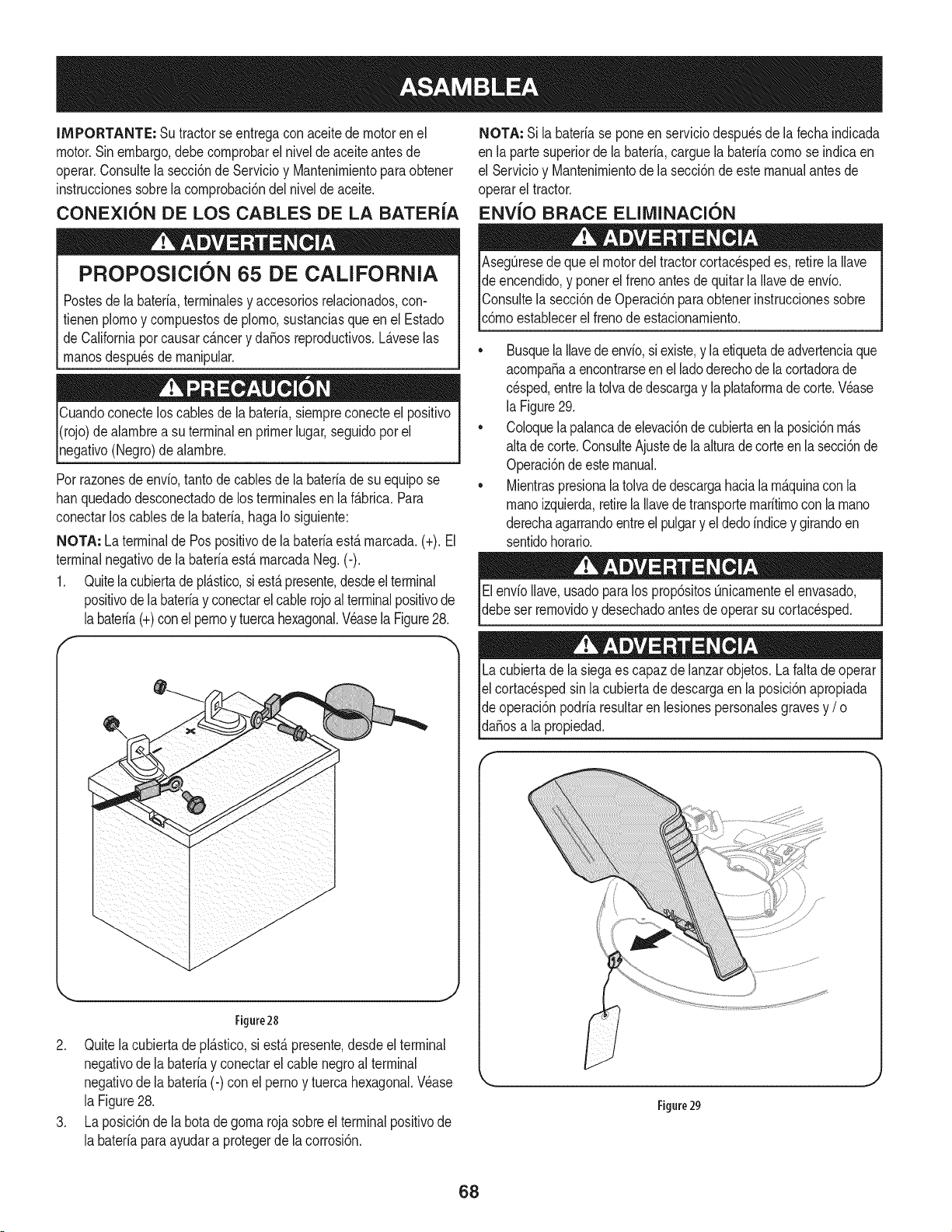
IMPORTANTE: Su tractorseentregaconaceitedemotoren el
motor.Sinembargo,debecomprobarel nivelde aceiteantes de
operar.Consultela secci6nde Servicioy Mantenimientoparaobtener
instruccionessobrelacomprobaci6ndel nivelde aceite.
CONEXION DE LOS CABLES DE LA BATER{A
PROPOSlClON 65 DE CALiFORNiA
Postesdela bateria,terminalesy accesoriosrelacionados,con-
fienen plomoy compuestosde pJomo,sustanciasqueen el Estado
de Californiaporcausarc_.ncery daSosreproducfivos.L_.veselas
manosdespu_sde manipular.
Cuandoconecteloscablesde la bateria,siempreconecteel posifivo
I(rojo)de alambrea su terminalenprimerlugar,seguidoporel
pgafivo (Negro)de alambre.
Porrazonesde envb, tantode cablesde la bateriade su equipose
hanquedadodesconectadode los terminalesen laf_.brica.Para
conectarlos cablesde la bateria,haga Io siguiente:
NOTA: La terminalde Pospositivode la bateriaest,.marcada.(+). El
terminalnegativode labateriaest&marcadaNeg. (-).
1. Quitela cubiertade pl&stico,si est&presente,desdeelterminal
positivode labateriay conectarel cablerojoal terminalpositivode
labateria(+)conel pernoy tuercahexagonal.Veasela Figure28.
J
J
J
J
J
J
Figure28
2. Quitelacubierta de plAsfico,si estApresente,desdeel terminal
negafivode la bateriay conectarel cable negroal terminal
negativode la bateria(-) con el perno y tuercahexagonal.Wase
la Figure28.
3. La posici6nde la botadegoma rojasobreel terminalposifivode
la bateriaparaayudara protegerde la corrosi6n.
NOTA: Si la bateriase poneen serviciodespu_sde la fechaindicada
en la partesuperiorde la bateria,carguela bateriacomo se indicaen
el Servicioy Uantenimientodela secci6ndeeste manualantesde
operarel tractor.
ENVJO BRACE ELllVlINACIC)N
AsegQresedequeel motordel tractorcortacespedes, retirelaIlave
de encendido,y ponerel frenoantesde quitarla Ilavedeenvio.
IConsultela secci6nde Operaci6nparaobtenerinstruccionessobre
lc6moestaNecerel frenode estacionamiento.
• Busquela Ilavedeenvio,siexiste,y laetiquetade advertenciaque
acompaSaa encontrarseenel ladoderechode la cortadorade
cesped,entrela tolvade descargay laplataformadecorte.Wase
la Figure29.
• CoJoquela palancade elevaci6ndecubiertaen laposici6nm_.s
altade corte.ConsulteAjustede la alturade corte en la secci6nde
Operaci6ndeestemanual.
• Mientraspresionala toJvadedescargahaciala m_.quinacon la
manoizquierda,retirela Ilavede transportemaritimoconla mano
derechaagarrandoentreel pulgary el dedoindicey girandoen
sentidohorario.
ElenvioIlave,usadoparalos prop6sitosQnicamenteel envasado,
debeser removidoy desechadoantesde operarsu cortacesped.
Lacubiertade la siegaes capazdelanzarobjetos.La faltade operar
el cortac_spedsin la cubiertade descargaen la posici6napropiada
de operaci6npodriaresultarenlesionespersonalesgravesy / o j
lda_osa a propedad. j
Figure29
,,J
68
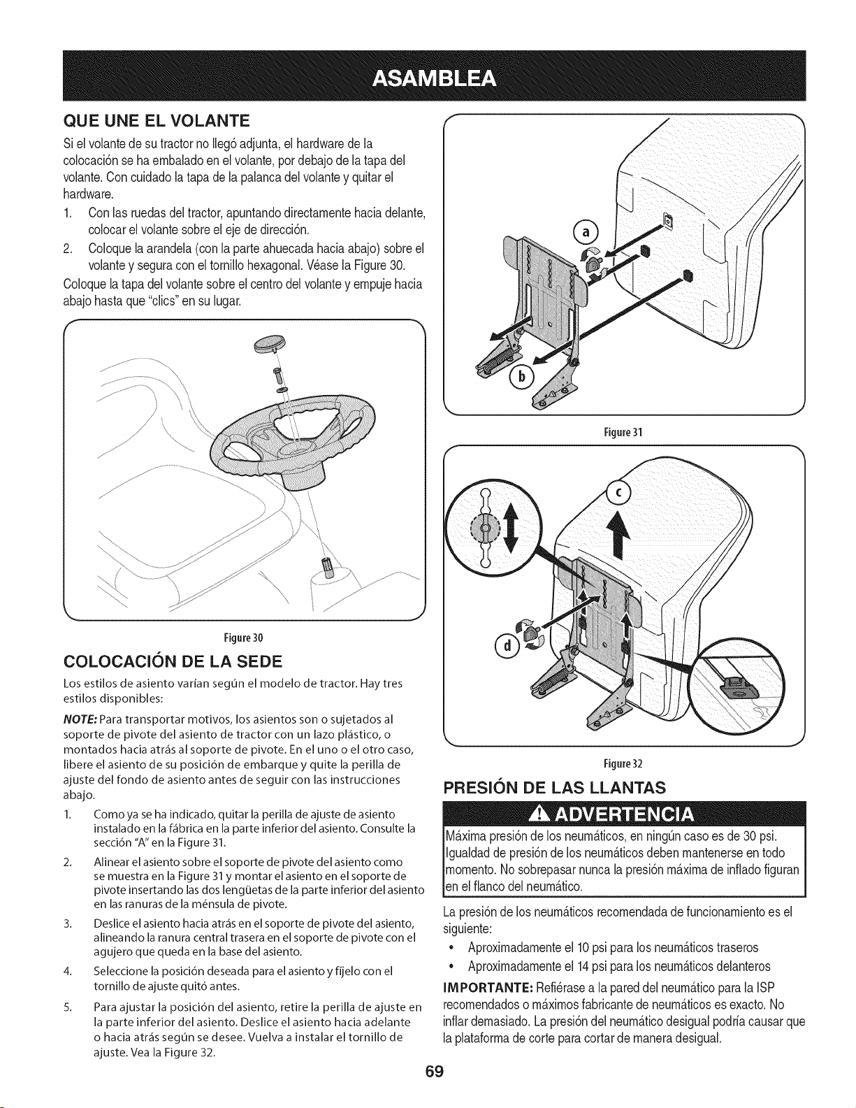
QUE UNE EL VOLANTE
Siel volantedesu tractorno Ileg6adjunta,el hardwarede la
colocaci6nse ha embaladoen el volante,por debajode latapadel
volante.Concuidadolatapa dela palancadel volantey quitarel
hardware.
1. Conlas ruedasdel tractor,apuntandodirectamentehaciadelante,
colocarel volantesobreel ejede direcci6n.
2. Coloquela arandela(con la parteahuecadahaciaabajo) sobreel
volantey seguracon el tornillohexagonal.Wase la Figure30.
Coloquela tapadel volantesobreel centrodel volantey empujehacia
abajohastaque "clics"en su lugar.
I
Figure31
Figure30
COLOCACiON DE LA SEDE
Los estilos de asiento varian segun el modelo de tractor. Hay tres
estilos disponibles:
NOTE: Para transportar motivos, los asientos son o sujetados al
soporte de pivote del asiento de tractor con un lazo pl_stico, o
montados hacia atr&s al soporte de pivote. En el uno o el otro caso,
libere el asiento de su posici6n de embarque y quite la perilla de
ajuste del rondo de asiento antes de seguir con las instrucciones
abajo.
1. Como ya se ha indicado, quitar la perilla de ajuste de asiento
instalado en la f_brica en la parte inferior del asiento. Consulte la
secci6n "A" en la Figure 31.
2. Alinear el asiento sobre el soporte de pivote del asiento como
se muestra en la Figure 31 y montar el asiento en el soporte de
pivote insertando las dos lengOetas de la parte inferior del asiento
en las ranuras de la m6nsula de pivote.
3. Deslice el asiento hacia atr&s en el soporte de pivote del asiento,
alineando la ranura central trasera en el soporte de pivote con el
agujero que queda en la base del asiento.
4. Seleccione la posici6n deseada para el asiento y fijelo con el
tornillo de ajuste quit6 antes.
5. Para ajustar la posici6n del asiento, retire la perilla de ajuste en
la parte inferior del asiento. Deslice el asiento hacia adelante
o hacia atr&s segun se desee. Vuelva a instalar el tornillo de
ajuste. Vea la Figure 32.
Figure32
PRESION DE LAS LLANTAS
M&ximapresi6nde los neumaticos,en ningOncasoes de30 psi.
Igualdadde presi6nde los neum&ticosdeben mantenerseen todo
momento.I/o sobrepasarnuncala presi6nm&ximade infiadofiguran
_ene f anco de neum&tco.
Lapresi6nde los neum&ticosrecomendadade funcionamientoes el
siguiente:
• Aproximadamenteel 10psi paralos neum_.ticostraseros
• Aproximadamenteel 14psi paralos neum_.ticosdelanteros
IMPORTANTE: Refi_rasea la pareddel neum_.ticoparala ISP
recomendadoso m_.ximosfabricantede neum_.ticoses exacto.No
inflardemasiado.Lapresi6ndel neum_.ticodesigualpodriacausarque
laplataformade corteparacortarde maneradesigual.
69
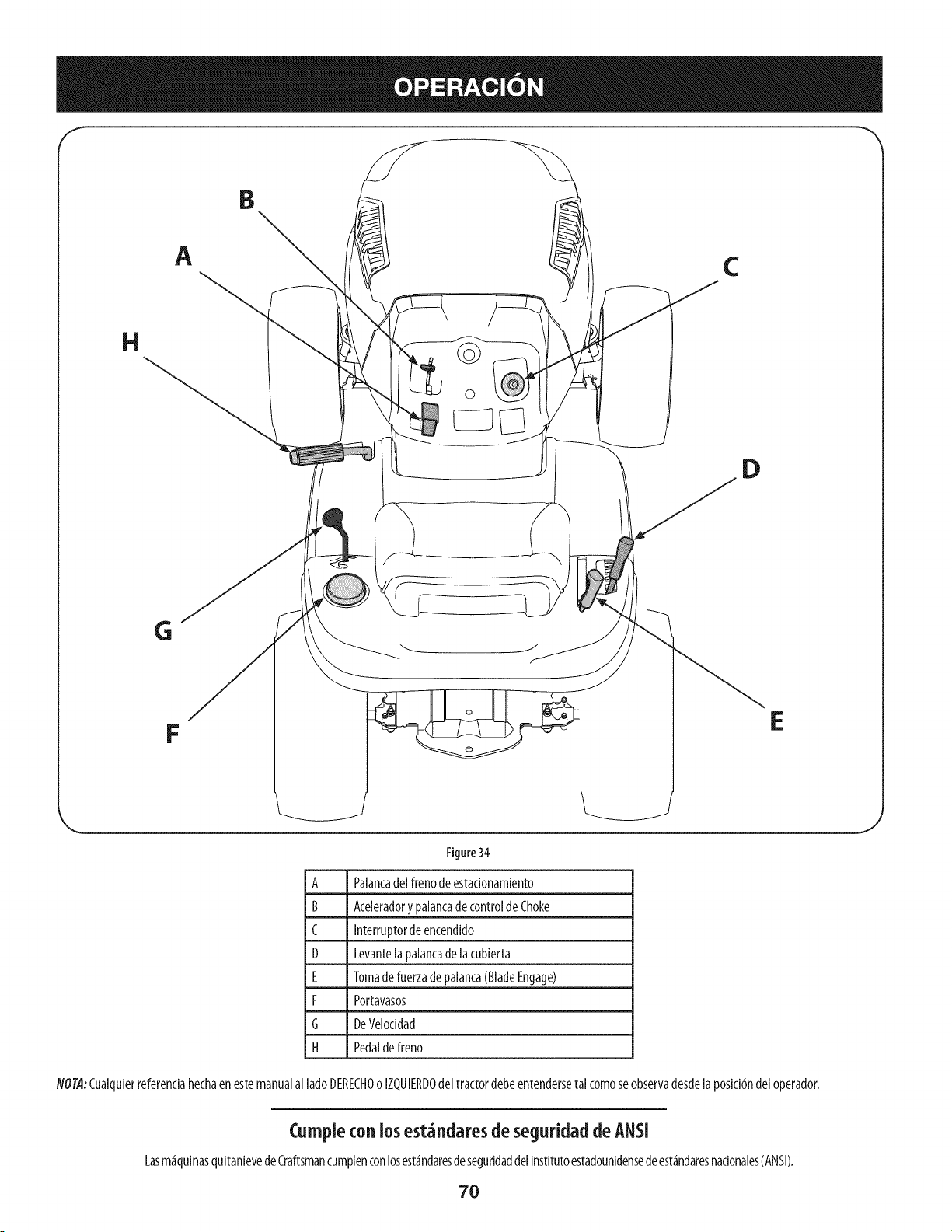
A
C
H
©
D
G
F
E
Figure34
A Palancadel frenodeestadonam[ento
B Aceleradorypalancade controlde Choke
C Interruptordeencend[do
D Levante[apa[ancade[acubierta
E Tomadefuerzadepalanca(BladeEngage)
F Portavasos
G DeVeloddad
H Pedaldefreno
NOTA:Cualqu[erreferendahechaenestemanualal ladoDERECHOoIZQUIERDOdeltractordebeentendersetal comoseobservadesdela posidbndeloperador.
Curnpiecon losest_ndaresde seguridad deANSi
Lasm_iqu[nasqu[tan[evedeCraftsmancumplenconlosest_indaresdesegur[daddel[nstitutoestadounidensedeest_indaresnadonales(ANSI).
70
J
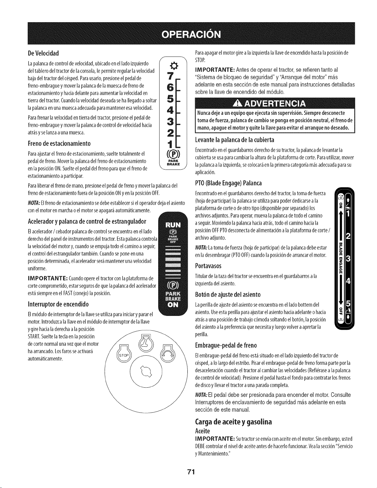
DeVeloddad
Lapalancade controldeveloddad,uNcadoen elladoizquierdo
deltablerodeltractordelaconsola,le permiteregularla veloddad
bajadeltractordelc_sped.Parausarlo,presioneel pedalde
freno-embraguey moverlapalancadela muescade frenode
estadonamientoy hadadelanteparaaumentarlaveloddaden
tierradeltractor.Cuandolaveloddaddeseadaseha llegadoasoltar
lapalancaenunamuescaadecuadaparamanteneresavelocidad.
Parafrenarlaveloddadentierradel tractor,presioneelpedalde
freno-embraguey moverlapalancadecontroldeveloddadhada
atr_sy selanzaaunamuesca.
Frenode estadonamiento
Paraajustarelfrenodeestadonamiento,sueltetotalmenteel
pedaldefreno.Moverlapalancadelfrenodeestadonamiento
enlaposid6nON.Suelteelpedaldelfrenoparaqueelfrenode
estadonamientoapartidpar.
ParaIiberarelfrenode mano,presioneelpedaldefrenoy moverlapalancadel
frenodeestadonamientofuerade laposki6nONyen laposki6nOFF.
flO@:Elfrenodeestadonamientosedebeestablecersi eloperadordejaelasiento
conel motoren marchaoel motorseapagar_autom_tkamente.
Aceleradory palancade controldeestrangulador
Elacelerador/ cebadorpalancadecontrolseencuentraenel lado
derechodel panelde instrumentosdeltractor.Estapalancacontrola
laveloddaddelmotory,cuandoseempujatodoelcaminoaseguir,
elcontroldel estranguladortambi(!n.Cuandoseponeenuna
posici6ndeterminada,elaceleradorser_mantenerunaveloddad
uniforme.
IMPORTANTE: (uandoopereeltractorconlaplataformade
cortecomprometido,estarsegurosdequelapalancadel acelerador
est_siempreenel FAST(conejo)laposid6n.
Interruptor de encendido
Elm6dulode interruptorde lallaveseutllizaparainiciarypararel
motor.Introduzcalallaveenelm6dulodeinterruptordelallave
ygire hadaladerechaalaposid6n
START.Sueltelateclaen laposid6n
decortenormalunavezqueelmotor
haarrancado.Losfarosseactivar_
autom_ticamente.
ParaapagarelmotorgirealaizquierdalaIlavedeencendidohastalaposid6nde
STOP.
IMPORTANTE: Antesde operarel tractor,se refierentanto al
"Sistemade bloqueodeseguridad"y "Arranquedelmotor"m&s
adelanteenesta secci6nde este manualparainstruccionesdetalladas
sobrela Ilavedeencendidodel m6dulo.
Nuncadejeaunequipoqueejecutasinsupervisi6n.Siempredesconecte
tomadefuerza,palancadecambiosepongaenposici6nneutral,el frenode
mano,apagueel motory quitelallaveparaevitarel arranquenodeseado.
Levantela palancade la cubierta
Encontradoenel guardabarrosderechodesutractor,la palancadelevantarla
cubiertaseusaparacamNarlaalturade laplataformadecorte.Parautilizar,mover
lapalancaala izquierda,secolocar_enla primeracategoriam_sadecuadaparasu
aplkad6n.
PTO(BladeEngage)Palanca
Encontradoenel guardabarrosderechodeltractor,latomade fuerza
(hojadeparticipar)lapalancaseutilizaparapoderdedicarsea la
plataformade corteode otrotipo (disponibleporseparado)los
archivosadjuntos.Paraoperar,muevala palancadetodoelcamino
aseguir.Moviendola palancahadaatr_s,todoelcaminohadala
posid6nOFFPT0desconectade alimentad6nalaplataformade corte/
archivoadjunto.
NOT/!:Latomadefuerza(hojade partidpar)delapalancadebeestar
en ladesembragar(PT0OFF)cuandolaposid6ndearrancarelmotor.
Portavasos
Titulardelatazadeltractorseencuentraenel guardabarrosala
izquierdadelasiento.
Bot6n de ajuste del asiento
Laperilladeajustede[asientoseencuentraen elladobottemde[
asiento.Useestaperillaparaajustarel aslentohadaadelanteohada
atr_sa unaposki6ndetrabajoc6modasoltandoelbot6n,laposici6n
delasientoala preferendaquenecesitay luegovolveraapretarla
perilla.
Embrague-pedalde freno
Elembrague-pedaldelfrenoest_situadoenelladoizquierdodeltractorde
c_sped,aIolargodelestribo.Pisarelembrague-pedaldefrenoformaparteporla
desacelerad6ncuandoeltractoralcambiarlasveloddades(Refi(!rasealapalanca
decontroldeveloddad).Presioneelpedalhastael rondoparacontratarlosfrenos
dediscoyllevareltractoraunaparadacompleta.
flOrA:Elpedaldebeser presionadapara encenderel motor.Consulte
Interruptoresde enclavamientode seguridadm_s adelanteenesta
secd6nde este manual.
Cargade aceite y gasoliaa
Aceite
IM PORTANTE: Sutractorseenviaconaceiteen elmotor.Sinembargo,usted
DEBEcontrolarel niveldeaceiteantesde hacerlofundonar.Yealasecd6n"Servicio
y Mantenimiento."
71
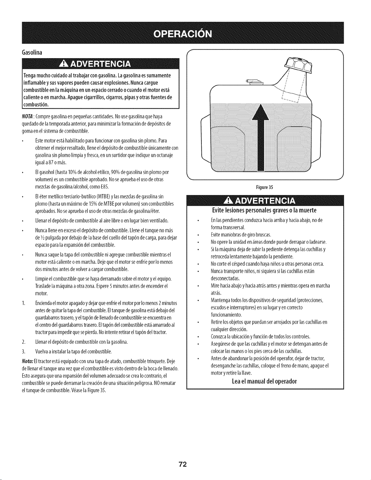
Gasolina
Tengamuchocuidadoal trabajarcongasolina.Lagasolinaessumamente
inflamabley susvaporespuedencausare×plosiones.Nuncacargue
combustibleen la m_quinaen un espaciocerradoocuandoel motor est_
caliente oen marcha.Apaguecigarrillos, cigarros,pipasy otrasfuentesde
combusti6n.
NOTA: Compregasolinaen pequeffascantidades.Nousegasolinaquehaya
quedadodelatemporadaanterior,paraminimizarlaformaci6nde dep6sitosde
gomaenel sistemadecombustible.
Estemotorest_habilitadoparafuncionarcongasolinasin plomo.Para
obtenerelmejorresultado,lleneel dep6sitode combustibleunicamentecon
gasolinasinplomolimpiay fresca,en unsurtidorqueindiqueunoctanaje
iguala87o m_s.
Elgasohol(hasta10%de alcoholetilico,90%degasolinasinplomopor
volumen)esun combustibleaprobado.Noseapruebaelusodeotras
mezclasdegasolina/alcohol,comoE85.
El(_termetflicoterciario-butflico(MTBE)y lasmezclasdegasolinasin
plomo(hastaunm_ximode 15%deMTBEporvolumen)soncombustibles
aprobados.Noseapruebael usodeotrasmezclasde gasolina/(!ter.
Llenarel dep6sitodecombustiblealairefibreoen lugarbienventilado.
Nuncalleneenexcesoeldep6sitode combustible.Lleneeltanquenom_s
deI/2pulgadapordebajode labasedel cuellodeltap6ndecarga,paradejar
espacioparala expansi6ndel combustible.
Nuncasaquelatapadel combustibleniagreguecombustiblemientrasel
motorest_calienteoen marcha.DejequeelmotorseenfrieporIomenos
dosminutosantesdevolveracargarcombustible.
Limpieel combustiblequesehayaderramadosobreelmotory elequipo.
Trasladela m_quinaaotrazona.Espere5minutosantesdeencenderel
motor.
I. Enciendaelmotorapagadoy dejarqueenfrieelmotorporIomenos2minutos
antesdequitarlatapadelcombustible.Eltanquedegasolinaest_debajodel
guardabarrostrasero,yel tap6ndellenadodecombustibleseencuentraen
elcentrodelguardabarrostrasero.Eltap6ndelcombustibleest_amarradoal
tractorparaimpedirquesepierda.Nointenteretirarel tap6ndeltractor.
2. Llenarel dep6sitodecombustibleconlagasolina.
3. Vuelvaa instalarlatapadelcombustible.
Nora:Eltractorest_equipadoconunatapadeatado,combustibletrinquete.Deje
dellenareltanqueunavezqueelcombustibleesvistodentrode la bocadellenado.
Estoaseguraqueunaexpansi6ndel volumenadecuadosecreaIocontrario,el
combustiblesepuedederramarlacreaci6ndeunasituaci6npeligrosa.NOrematar
eltanquede combustible.VdaselaFigure35.
Figure35
Evite lesionespersonalesgraveso la muerte
Enlaspendientesconduzcahaciaarribay haciaabajo,node
formatransversal.
Evitemaniobrasdegirobruscas.
Nooperelaunidaden_reasdondepuedederraparoladearse.
Silam_quinadejade subirlapedientedetengalascuchillasy
retrocedalentamentebajandolapendiente.
Nocorteelc(_spedcuandohayaniffosu otraspersonascerca.
Nuncatransporteniffos,ni siquierasilascuchillasest_n
desconectadas.
Mirehaciaabajoy haciaatr_santesy mientrasoperaen marcha
atr_s.
Mantengatodoslosdispositivosdeseguridad(protecciones,
escudoseinterruptores)ensulugaryen correcto
fundonamiento.
Retirelosobjetosquepuedanserarrojadosporlascuchillasen
cualquierdirecci6n.
Conozcalaubicaci6ny funci6ndetodosloscontroles.
Aseguresedequelascuchillasy elmotorsedetenganantesde
colocarlasmanoso lospiescercadelascuchillas.
Antesdeabandonarlaposici6ndeloperafor,dejarde tractor,
desenganchelascuchillas,coloqueelfrenode mano,apagueel
motory retirelallave.
Leael manual del operador
72
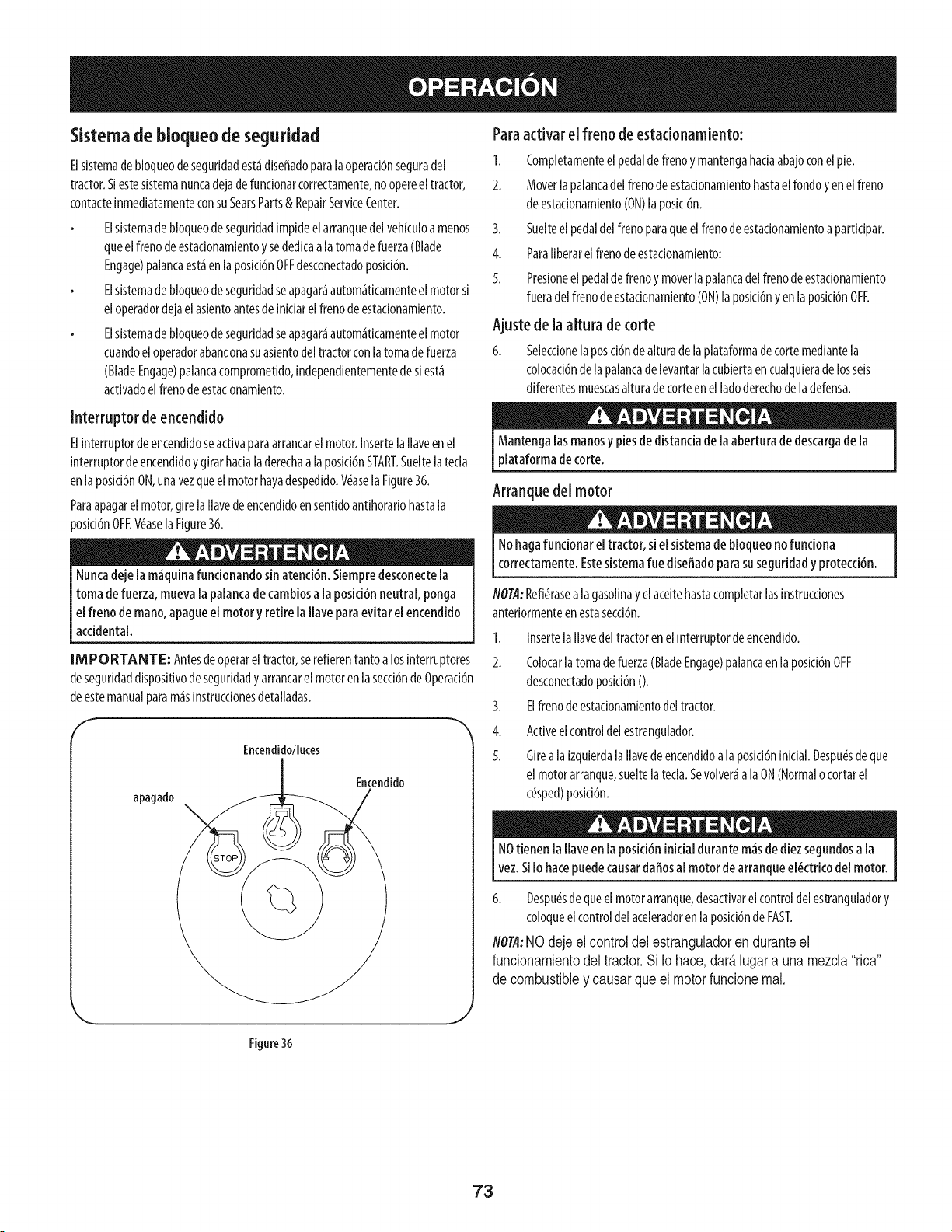
Sistemadebloqueode seguridad
Elsistemade bloqueodeseguridadest_diseffadoparalaoperad6nseguradel
tractor.Siestesistemanuncadejadefuncionarcorrectamente,no opereeltractor,
contacteinmediatamenteconsuSearsParts& RepairServiceCenter.
Elsistemade bloqueode seguridadimp[deelarranquedelvehkuloamenos
queelfrenodeestacionamientoy sededkaalatomadefuerza(Blade
Engage)palancaest_enlaposki6nOFFdesconectadoposki6n.
Elsistemade bloqueode seguridadseapagar_autom_tkamenteelmotorsi
eloperadordejael asientoantesde inkiarel frenodeestacionamiento.
Elsistemade bloqueode seguridadseapagar_autom_ticamenteelmotor
cuandoeloperadorabandonasuasientodeltractorconlatomade fuerza
(BladeEngage)palancacomprometido,independientementedesiest_
activadoelfrenodeestadonamiento.
Paraactivar el freno de estadonamiento:
1. Completamenteelpedaldefrenoymantengahaciaabajoconelpie.
2. Moverlapalancadelfrenodeestacionamientohastael rondoyen elfreno
de estadonamiento(ON)la poski6n.
3. Suelteel pedaldelfreno paraqueelfrenode estadonamientoapartidpar.
4. Paraliberarel frenodeestadonamiento:
5. Presioneel pedalde frenoymoverla palancadelfrenodeestadonamiento
fueradelfrenodeestadonamiento(ON)laposid6nyen laposici6nOFF.
Ajuste de la altura de torte
6. Seleccionelaposki6ndealturadelaplataformade cortemediantela
colocaci6nde lapalancade levantarlacubiertaencualquierade losseis
diferentesmuescasalturade corteenel ladoderechodeladefensa.
Interruptor de encendido
Elinterruptordeencendidoseactivaparaarrancarelmotor.InsertelaIlaveen el
interruptordeencendidoy girarhadala derechaa laposki6nSTART.Sueltelatecla
enlaposki6nON,unavezqueel motorhayadespedido.V(_aselaFigure36.
Paraapagarelmotor,girelaIlavedeencendidoensent[doantihorariohastala
_osid6nOFF.V_asela Figure36.
Nuncadeje [a m_quinafuncionandosinatenci6n.Siempredesconecte[a
toma defuerza, mueva[a palancade cambiosa la posici6nneutral, ponga
elfreno de mano,apagueel motory retire [aIlave paraevitar el encendido
accidental.
[NIPORTANTE: Antesdeoperareltractor,serefierentanto alosinterruptores
deseguridaddispositivode seguridady arrancarel motorenlasecd6ndeOperad6n
deestemanualparam_sinstrucdonesdetalladas.
f
Encendido/luces
apagado
Encendido
Mantengalasmanosy piesdedistanciadela aberturadedescargade la
plataforma de corte.
Arranque del motor
Nohagafuncionar el tractor, siel sistemade bloqueo nofunciona
correctamente.Estesistemafue diseffadoparasuseguridady protecd6n.
NOTA:Refi_rasealagasolinayelaceitehastacompletarlasinstrucdones
anteriormenteenestasecd6n.
1.
2.
3.
4.
5.
InsertelaIlavedel tractoren elinterruptordeencendido.
Colocarla tomade fuerza(BladeEngage)palancaenla posid6nOFF
desconectadoposki6nO.
Elfrenode estadonamientodeltractor.
Activeel controldelestrangulador.
Girea laizquierdalaIlavedeencendidoala posici6ninidal.Despu_sdeque
el motorarranque,sueltelatecla.Sevolver_a laON(Normalo cortarel
c(_sped)posid6n.
NOtienen la flare en laposici6ninicialdurante m_sdediez segundosa la
vez.SiIo hacepuedecausardaffosal motor de arranqueel_ctricodel motor.
6. Despu_sdequeelmotorarranque,desactivarelcontroldelestranguladory
coloqueelcontroldelaceleradorenlaposid6ndeFAST.
NOTA:NOdejeel oontroldelestranguladoren duranteel
fundonamientodel traotor.Si Io haoe,dar_lugara unamezda"rioa"
de oombustibley oausarqueel motorfunoionereal.
J
Figure36
73
Parodel motor
Sisegolpeaun objeto e×traffo,detengael motor,desconecteel cablede la
bujia (s)y tierra contra el motor. Inspeccionarcuidadosamenteel equipo de
losdaffos.Reparaci6nde losdaffosantesde reiniciary defuncionamiento.
1. Sisededlcanalashojas,colocarlatomadefuerza(BladeEngage)palancaen
laposid6nOFFdesconectadoposid6nO.
2. @e alaizquierdalaIlavedeencendidoa laposici6nSTOR
3. RetirelaIlavedelaIlavedeencendidoparaevitarelarranqueno deseado.
Laconducd6n del tractor
Evitecomienzapronto, el excesodevelocidady paradasbruscas.
Nodejeel asientodel tractor, sin colocarlatoma defuerza(Blade Engage)
palancaen laposici6nOFFdesembragar0 posici6n,presionandoel pedalde
ffeno y accionadoel freno de estacionamiento.Sino puedesalir del tractor
sinvigilanda, tambi_n asuvezla llavede encendidoapagadoy guitar la
llave.
Siempremire haciaabajoy detr_santesy durante lacopiadeseguridad
paraevitar lacopiade m_s de un acddente.
1. Pisarel embrague-pedaldefrenoparaliberarelfrenodeestacionamientoy
dejarqueel pedal.
2. Moverlapalancadelaceleradorenel FAST(conejo)laposicidn.
3. Coloquelapalancadecambiostantoenla posici6ninversao FORWARD.
IM PORTANTE: NOutilizarlapalancadecambiosparacambiarladirecci6nde
lamarchacuandoeltractorest_enmovimiento.Siempreutiliceelfrenode pedalde
embragueparaqueeltractoraunaparadacompletaantesde pasar.
4. Suelteelfrenodeestacionamientopresionandoelembrague-pedaldefreno
y elposicionamientodelapalancadecontroldevelocidadenla posici6n
deseada.
IM PORTANTE: Tiempo,losoperadoresdebenutilizarposicionesdeveloddad
de1o 2.Convi_rtetetotalmentefamlllarlzadoconelfundonamlentodeltractory
loscontrolesantesdeoperareltractoren lospuestosdemayorvelocidad.
5. Embrague-pedaldefrenolentamenteparacolocarlaunidadenmovimiento.
6. Eltractorde c_spedesIlevadoaunaparadapresionandoel embrague-pedal
defreno.
NOTA:Cuandooperelaunidadinidal,habr_pocadiferendaentrelasdos
velocidadesm_saltashastadespu_sdeloscinturonessehansentadoenlaspoleas
duranteelper[ododerodaje.
Antesdeabandonarla posici6ndel operadorpor cualquierraz6n,
separarlas hojas,ponerlapalancade controlde velocidaden
I neutral,pongaelfreno de estacionamiento,paradamotorapagadoy
[ quitarla Ilave.
INIPORTANTE: AIparareltractor,porcualquiermotivo,mientrasqueenuna
superficiede hierba,siempre:
1. Coloquelapalancadecambiosen puntomuerto,
2. Apliqueelfrenodeestacionamiento,
3. Apagueel motory quitar laIlave.SiIohace,reducir,_alm[nimolaposibilidad
dequesuc_spedsedore'"'porelescapecalientedel motordesutractor.
Siseestancalaunidadconelcontrolde velocidadenaltaveloddad,o silaunidad
no funcionar_conla palancadecontroldevelocidadencondicionesde baja
velocidad,sigaestospasos:
I. Lapalancadecambiosen puntomuerto.
2. Reinicieelmotor.
3. Coloquelapalancadecontrolde veloddadenlaposid6nm_saltaveloddad.
4. Embrague-pedaldefrenocompletamente.
5. Plsarelembrague-pedaldefreno.
6. Coloquelapalancadecontrolde veloddadenlaposid6ndeseada.
7. Coloquelapalancadecambiosencualquierade avanceoretroceso,y seguir
losprocedimientosnormalesdefundonamiento.
Conducd6nen las laderas
Refierenalanchode lapendienteenlaseguridaddelaspr_cticasdeoperaci6n
lmportantesecci6ndel manualparaayudaradetermlnarzonasdeladen donde
puedeoperarel tractorcontotal seguridad.
A
Nocorte el c_speden pendientesconunainclinaci6nde m_sde 15grados
(un aumentode aproximadamente2412piescada10 pies).Eltractor puede
volcarycausarlesionesgraves.
Corteel c#spedy laspendientes,nuncatransversal.
Tengaextremaprecaud6nalcambiarde direcci6nen laspendientes.
Watchparalosagujeros,grietas,baches,piedrasuotrosobjetosocultos.
Terrenoirregularpuederevertirla m_quina.Elc#spedalto puedeocultar
obst_culos.
Evitegirarcuandosecirculaporunapendiente.Siunavez,debehacerse,a
suvezpotlapendiente.Elregresodeunapendienteaumentalaposibilidad
de unroll over.
Evitedetenersecuandoseconduceporunapendiente.Siesnecesario
detenermientrasseconduceporunapendiente,puestaen marchasin
problemasyconcuidadoparareducirlaposibilidaddevolteareltractor
hadaatr_s.
74
Involucrar a losBlades
PartJcipacJ6nde [atomadefuerza(BladeEngage)lastransferenciasdeenergiaala
plataformadecorteodeotrotipo(disponibleporseparado)losarchivosadjuntos.Para
partidpardelashojas,hagaIoslgulente:
I. Moverlapalancade controldelaceleradora lar@ida(conejo)laposicJ6n.
2. Sujetelatomadefuerza(BladeEngage)y girar lapalancade todoel camlno
asegulralosnovJos(ON)laposid6n.
3. Mantengalapalancadelaceleradorenel FAST(conejo)la posici6nparael
usom_seficientede laplataformade corteo deotrotJpo(dlsponlblepor
separado)losarchlvosadjuntos.
iMPORTANTE: En el reverso Precauci6n modo que el motor se
apagar_,autom_.tJcamentesJla toma de fuerza est,. comprometida con
la palanca de control de velocJdad en la posJcJ6ninversa para vJajar
con la Ilave de encendido en la posJcJ6nnormal de sJega.
Osode la cubiertade Levantela palanca de
Paraelevarlaplataformadecorte,moverlapalancade elevaci6nde cubiertaala
izquierda,luegosecolocaen laranuram_sadecuadaparasuaplicaci6n.Consulte
Ajustelaalturadecorteanterlormenteenestaseccl6n.
Cortar
Paraayudara evitar elcontacto conla cuchillao unalesi6nen el objeto
lanzado,Mantengaa losespectadores,los ayudantes,los niffosylas
mascotasporIo menos75piesdedistanciadela m,_quinamientrasest,_en
funcionamiento. Paradade la m,_quina,si alguien entra en el,_rea.
Fal'os
Lasl&mparasest&nONcuandoel motordeltractorseest&ejecutando.
Laslucesseapagacuandolallavedecontactosemuevea la posici6nSTOP.
LasiguJenteinformaci6nser_t_tJlcuandoseutJlizalaplataformadecorteconsu
tractor:
Plande supatr6n de corte paraevitar la descargade materiales hacialas
carreteras,aceras,transeuntes,etc.Adem,_s,evite material quesedescarga
contraunaparedo unaobstrucci6nquepuedecausaralia material a
rebotarhaciaeloperador.
Nocorteelc_speda la veioddaddeterrenoelevado,especlalmentes[seha
instaladoun kit de mantJlloocolectordec_sped.
Paraobtenerlosmejoresresultadosserecomiendaquelasdosprimeras
vueltassecortar_conlaaprobaci6ndelagesti6narrojadohaciaelcentro.
TraslasdosprJmerasvueltas,invertirelsentJdodelanzarla descargahacJael
exteriordelabalanzadecorte.Estoledar_unamejoraparienciaalc_sped.
Nocorteelc_speddemasJadocorto.Pastocortoinvitacrecimientodemalas
hierbasy losamarillosconrapidezeneltiemposeco.
Cortarel c_spedsiempresedebehacerconelmotoratodogas.
Bajolascon@Jonesm_spesadas,puedesernecesarJovolversobrelazona
delcorteporsegundavezparaobteneruncortelimpio.
NOJntentecortarespesamalezay malashierbasyelpastomuyalto.Sutractorest_
diseffadoparacortarelc_sped,uncepillonoest_daro.
Mantengalascuchillasafiladasy sustituirlascuchillasencasode desgaste.
ConsulteHojasdecorteen elservicioy laseccidnMantenimientodeeste
manualdeinstruccionesde afilarla hojaadecuada.
75
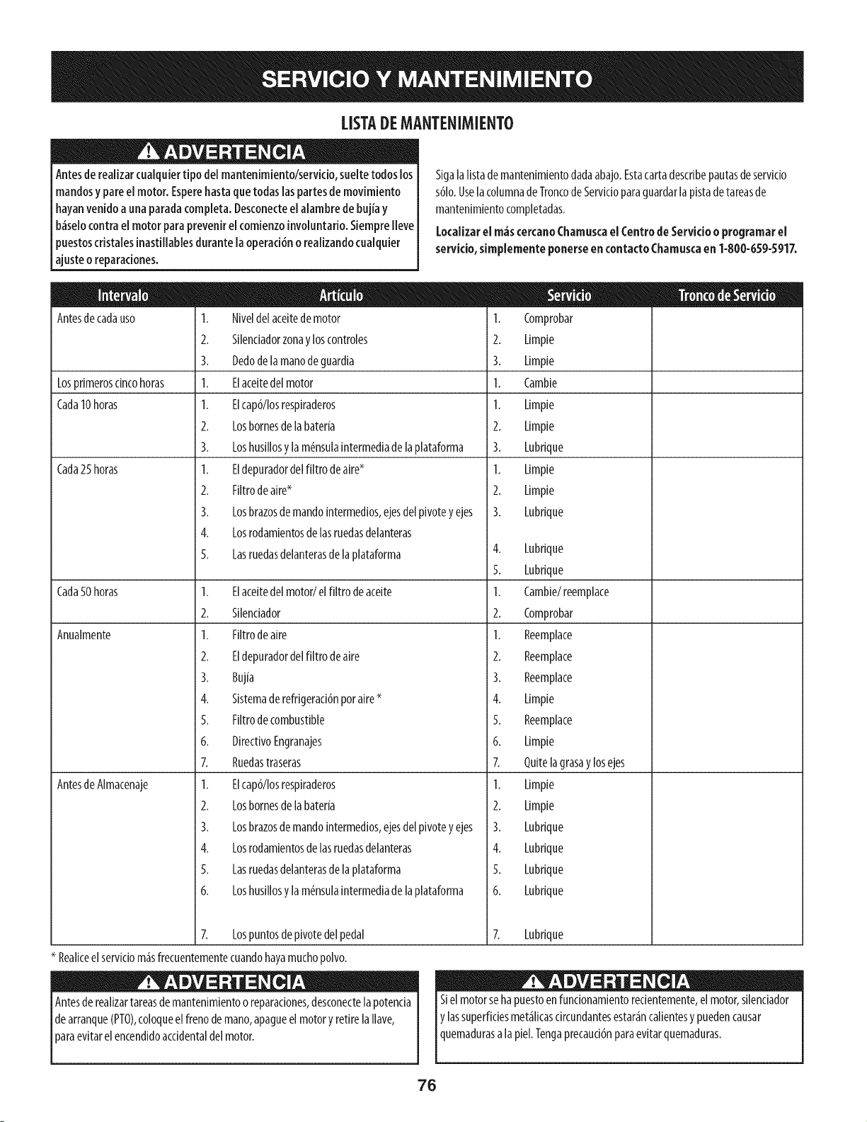
LISTADEMANTENIMIENTO
Antesde realizarcualquiertipo del mantenimiento/servicio,sueltetodoslos
mandosy pare el motor. Esperehastaquetodas laspartesdemovimiento
hayanvenido a unaparadacompleta.Desconecteel aiambrede bujiay
b_selocontrael motor paraprevenirel comienzoinvoluntario.SiempreIleve
puestoscristaiesinastillablesdurante la operaci6no reaiizandocualquier
ajusteo reparaciones.
Antesdecadauso
Losprimeroscincohoras
Cada10horas
Cada25horas
Sigalalistademantenimientodadaabajo.Estacartadescribepautasdeservicio
s61o.Uselacolumnade TroncodeServicioparaguardarlapistadetareasde
mantenimientocompletadas.
Local[zarel m_scercanoChamuscael Centrode Servicioo programarel
servicio, simplemente ponerse encontactoChamuscaen 1-800-659-5917.
1. Niveldel aceitedemotor
2. Silendadorzonay loscontroles
3. Dedode lamanodeguardia
1. Elaceitedel motor
1. Elcap6/Iosrespiraderos
2. Losbornesde labater[a
3. Loshusillosy la m_nsulaintermediade laplataforma
1. Eldepuradordel filtro deaire*
2. Filtrode aire*
3. Losbrazosdemando[ntermedios,ejesdelpivotey ejes
4. Losrodamientosdelasruedasdelanteras
5. Lasruedasdelanterasdelaplataforma
Cada50 horas 1. Elaceitedel motor/el filtro deaceite
2. Silenciador
Anualmente
AntesdeAlmacenaje
1.
2.
3.
1.
1.
2.
3.
1.
2.
3.
Comprobar
Limpie
Limpie
Cambie
Limpie
Limpie
Lubrique
Limpie
Limpie
Lubrique
4. Lubrique
5. Lubrique
1. Cambie/reemplace
2. Comprobar
1. Filtrode aire
2. Eldepuradordel filtro deaire
3. Buj[a
4. Sistemaderefrigerad6nporaire*
5. Filtrode combustible
6. DirectivoEngranajes
1.
2.
3.
4.
5.
6.
Reemplace
Reemplace
Reemplace
Limpie
Reemplace
Limpie
7. Ruedastraseras
1. Elcap6/Iosrespiraderos
2. Losbornesde labater[a
3. Losbrazosdemando[ntermedios,ejesdelpivotey ejes
4. Losrodamientosdelasruedasdelanteras
5. Lasruedasdelanterasdelaplataforma
6. Loshusillosy la m_nsulaintermediade laplataforma
7. Lospuntosde pivotedel pedal
* Realiceelserviciom_sfrecuentementecuandohayamuchopolvo.
LpAntesderealizartareasdemantenimiento desconectela
o
reparadones, potencia
de arranque(PTO),coloqueel frenodemano,apagueel motory retirelaIlave,
araevitarel encendidoaccidentaldelmotor.
7. Quitelagrasay losejes
1. Limpie
2. Limpie
3. Lubrique
4. Lubrique
5. Lubrique
6. Lubrique
7. Lubrique
Siel motorseha puestoenfuncionamientorecientemente,elmotor,silenciador
y lassuperficiesmet_licasdrcundantesestar_ncalientesy puedencausar
quemadurasa apie. Tengaprecauci6nparaevitarquemaduras.
76
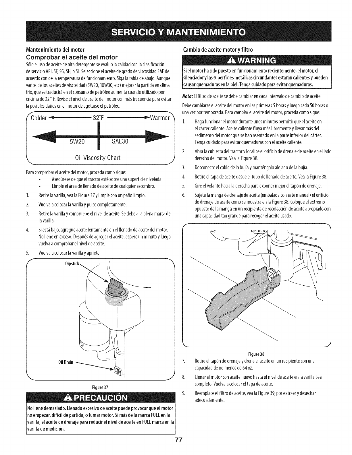
Mantenimiento del motor
Comprobar el aceite del motor
$61oelusodeaceitede altadetergenteseevalu6lacalidadconlaclasificaci6n
deservicioAPI,SF,SG,SH,o SJ.SeleccioneelaceitedegradodeviscosidadSAEde
acuerdocondelatemperaturadefuncionamiento.Sigalatabladeabajo.Aunque
variosdelosaceitesdeviscosidad(5W20,IOW30,etc)mejorarlapartidaenclima
frio,quesetraducir_ienelconsumodepetr61eoaumentacuandoutilizadopor
encimade32oF.Reviseel niveldeaceitedelmotorconm_isfrecuenciaparaevitar
laposiblesda_osenelmotordeagotarseelpetr61eo.
f'_older _ 32°F _Warmer_
Oil Viscosity Chart
J
Paracomprobarelaceitedelmotor,procedacomosigue:
AsegOresedequeeltractorest_sobreunasuperfidenivelada.
Limpieel _ireadeIlenadode aceitedecualquierescombro.
1. Retirelavarllla,vealaFigure37y IlmpleconunpahoIlmpio.
2. Vuelvaacolocarlavarillay pulsecompletamente.
3. Retirelavarillay compruebeelniveldeaceite.Sedebealaplenamarcade
lavarllla.
Siesthbajo,agregueaceitelentamenteenel Ilenadodeaceitedelmotor.
NoIleneenexceso.Despu_sdeagregarelaceite,espereunminutoy luego
vuelvaacomprobarel niveldeaceite.
4.
5. Vuelvaacolocarlavarillay apriete.
Oil Drain
Figure37
11ollene demasiado.Llenadoexcesivodeaceitepuedeprovocarqueel motor
no empezar,difkil de partida, o fumar motor. Sire,isde la marcaFULLen la
varilla, el aceitede drenajepara reducirel nivelde aceiteen FULLmarcaen la
varilla de medici6n.
Cambiodeaceite motor yfiltro
Neta: Elfiltro deaceitesedebecambiarencadaintervalodecambiode aceite.
Debecambiarseelaceitedel motorenlasprimeras5 horasy luegocada50 horaso
unavezpottemporada.Paracambiarelaceitedel motor,procedacomosigue:
1. Hagafundonarelmotorduranteunosminutospermitirqueelaceiteen
elc_irtercaliente.Aceitecalientefluyam_isIibrementey Ilevarm_isdel
sedimentodelmotorquesehanasentadoen la parteinferiordel c_irter.
Tengacuidadoparaevitarquemadurasconelaceitecaliente.
2. Abralacubiertadeltractory Iocaliceelorifido dedrenajedeaceiteenel lado
derechodelmotor.Veala Figure38.
3. Desconecteelcablede labujiay mant_ngaloalejadodela bujia.
4. Retireel tapadeaceitedesdeeltubode Ilenadodeaceite.Veala Figure38.
5. Gireel volantehadaladerechaparaexponermejoreltap6nde drenaje.
6. Sujetelamangadedrenajedeaceite(embaladaconestemanual)elorifido
de drenajede aceitecomosemuestraenla Figure38.Coloqueel extremo
opuestodelamangaen un redpientederecolecd6ndeaceiteapropiadocon
unacapacidadtan grandepararecogerelaceiteusado.
Figure38
7. Retireel tap6nde drenajey dreneelaceiteen unredpienteconuna
capaddaddeno menosde64oz.
8. Llenarelmotorconaceitenuevohastael niveldeaceiteen lavarillaLee
completo.Vuelvaacolocareltapadeaceite.
9. Reemplaceelfiltro deaceite,veala Figure39,potextraery desechar
adecuadamente.
77
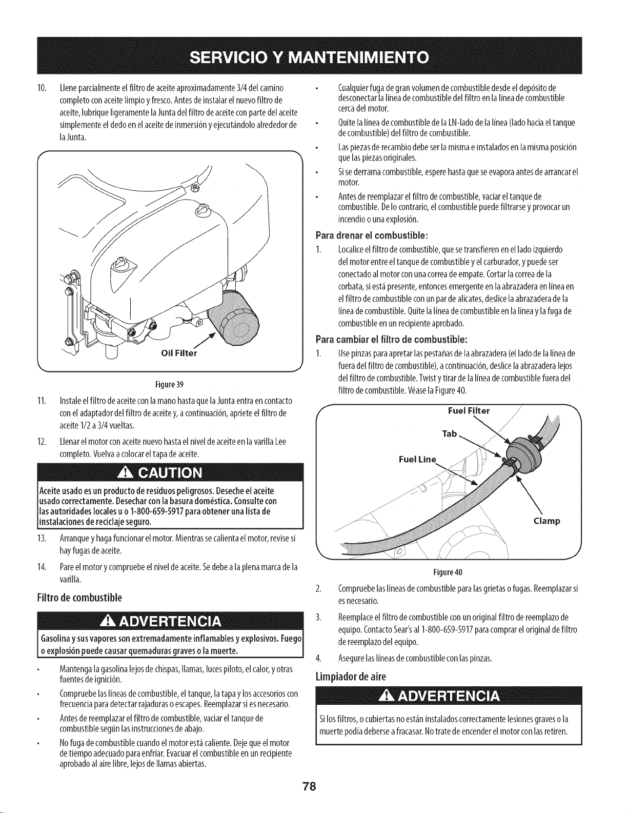
10.
Lleneparcialmenteelfiltro deaceiteaproximadamente3/4delcamino
completoconaceitelimpioyfresco.Antesde instalarel nuevofiltro de
aceite,lubriqueligeramentelaJuntadelfiltro de aceiteconpartedelaceite
simplementeeldedoen elaceitedeinmersi6ny ejecut_ndoloalrededorde
laJunta.
11.
12.
Oil Filter
Figure39
Instaleelfiltro de aceiteconlamanohastaquelaJuntaentraen contacto
conel adaptadordelfiltro deaceitey, acontinuaci6n,aprieteelfiltro de
aceiteI/2 a3/4vueltas.
Llenarel motorconaceitenuevohastaelniveldeaceiteenlavarillaLee
completo.Vuelvaacolocareltapade aceite.
Aceiteusadoesun productode residuospeligrosos,Desecheel aceite
usadocorrectamente.Desecharcon labasuradom_stica.Consultecon
lasautoridadeslocalesu o 1-800-659-5917paraobtener unalista de
instaladonesde redclaje seguro.
13. Arranquey hagafundonarel motor.Mientrassecalientaelmotor,revisesi
hayfugasdeaceite.
14. Pareelmotorycompruebeelniveldeaceite.Sedebeala plenamarcadela
varilla.
Filtro de combustible
Gasolinay susvaporessonextremadamenteinflamablesy explosivosoFuego
oexplosi6npuedecausarquemadurasgraveso lamuerte.
Mantengalagasolinalejosde chispas,llamas,lutespiloto,elcalor,y otras
fuentesdeignici6n.
Compruebelaslineasdecombustible,eltanque,la tapay losaccesorioscon
frecuendaparadetectarrajadurasoescapes.Reemplazarsi esnecesario.
Antesdereemplazarelfiltro decombustible,vaciareltanquede
combustiblesegtinlasinstrucdonesde abajo.
Nofugadecombustiblecuandoelmotorest_caliente.Dejequeelmotor
detiempoadecuadoparaenfriar.Evacuarelcombustibleenunrecipiente
aprobadoalairelibre,lejosdellamasabiertas.
Cualquierfugadegranvolumendecombustibledesdeeldep6sitode
desconectarlalineadecombustibledelfiltro enlalineade combustible
cercadelmotor.
QuitelalineadecombustibledelaLN-ladodelalinea(ladohaciaeltanque
decombustible)delfiltro decombustible.
Laspiezasde recambiodebeserlamismaeinstaladosen lamismaposici6n
quelaspiezasoriginales.
Sisederramacombustible,esperehastaqueseevaporaantesdearrancarel
motor.
Antesde reemplazarel filtro decombustible,vaciareltanquede
combustible.DeIocontrario,elcombustiblepuedefiltrarsey provocarun
incendioo unaexplosi6n.
Para drenar el combustible:
1. Localiceelfiltro decombustible,quesetransfierenenelladoizquierdo
del motorentreeltanquedecombustibleyelcarburador,y puedeser
conectadoalmotorconunacorreade empate.Cortarla correade la
corbata,siest_presente,entoncesemergenteenlaabrazaderaen lineaen
elfiltro de combustibleconun parde alicates,deslicelaabrazaderade la
I[neadecombustible.Quitelalineadecombustibleen laI[neay lafugade
combustibleen unredpienteaprobado.
Para cambiar el filtro de combustible:
1. Usepinzasparaapretarlaspestaffasde laabrazadera(el ladode lalineade
fueradelfiltro decombustible),a continuad6n,deslicelaabrazaderalejos
delfiltro de combustible.Twisty tirar de laI[neadecombustiblefueradel
filtro decombustible.V_aselaFigure40.
/
Fuel Filter /
\
Tab
Fuel Line
Figure40
Compruebelaslineasde combustibleparalasgrietasofugas.Reemplazarsi
esnecesario.
3. Reemplaceelfiltro decombustibleconunoriginalfiltro dereemplazode
equipo.ContactoSear'sal 1-800-659-5917paracomprareloriginaldefiltro
de reemplazodelequipo.
4. AsegurelasI[neasdecombustibleconlaspinzas.
Limpiador de aire
Silosfiltros,o cubiertasnoest_ninstaladoscorrectamentelesionesgraveso la
muertepodiadeberseafracasar.Notratede encenderelmotorconlasretiren.
78
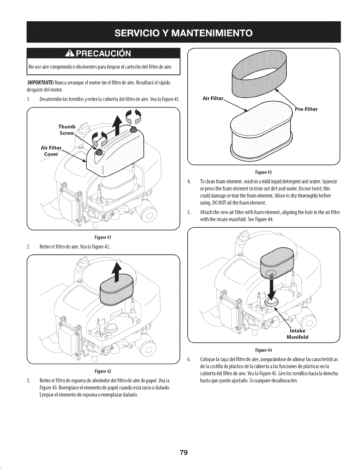
Nouseairecomprimidoo disolventesparalimpiarel cartuchodelfiltro deaire.
IMPORTANTE:Nuncaarranqueel motorsinel filtrode aire.Resultar_el r_pido
desgastedelmotor.
Desatornillelostornillosy retirelacubiertadelfiltro deaire.Yeala Figure41.
1.
f
Thumb
Screw
Air Filter
2.
Figure41
Retireel filtro deaire.Veala Figure42.
,J
3.
Figure42
Retireel filtro deespumadea[rededorde[filtro deairedepapeLVea[a
Figure43.Reemp[aceele[ementodepape[cuandoest_sucioodaffado.
Limpiarelelementodeespumaoreemplazardaffado.
Air Filter,
Figure43
4. Tocleanfoamelement,washina mildliquiddetergentandwater.Squeeze
orpressthe foamelementto rinseoutdirt andwater.Donottwist;this
coulddamageortearthefoamelement.Allowto dry thoroughlybefore
using.DONOToil thefoamelement.
5. Attachthe newair filter withfoamelement,aligningthe holein the airfilter
with the intakemanifold.SeeFigure44.
Manifold
Figure44
Coloque[atapade[fiitro deaire,asegur_ndosedealinearlascaracter[sticas
de [acostilladepi_sticode[acubiertaa [asfuncionesde pi_sticasen[a
cubiertadelfiltro deaire.VealaFigure45.Girelostorniiioshacia[aderecha
hastaquequedeajustado.Sicualquierdesalineaci6n.
79
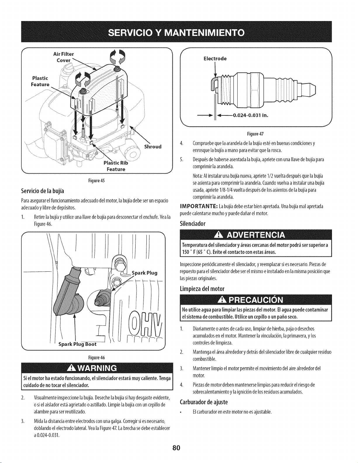
Air FilterCover
Plastic
Feature
Figure45
Serviciode la bujia
Paraasegurarel funcionamientoadecuadodel motor,labujiadebeserunespacio
adecuadoy librededep6sitos.
1.
f
Retirelabuj[ayutiliceunaIlavedebuj[aparadesconectarelenchufe.Yeala
Figure46.
Figure46
Siel motor ha estadofuncionando,elsiienciadorestar_muycaiiente.Tenga
cuidadodeno tocarel silenciador.
2. Visualmenteinspecdonelabuj[a.Desechelabuj[asi haydesgasteevidente,
osiel aisladorest_agrietadooastillado.Limpielabuj[aconuncepillode
alambreparasetreutilizado.
3. Midaladistanciaentreelectrodosconunagalga.Corregirsi esnecesario,
doblandoelelectrodolateral.Yeala Figure47.Labrechasedebeestablecer
a0.024-0.031.
Electrode
Figure47
4. Compruebequela arandeladelabujiaest_en buenascondicionesy
enrosquelabujiaamanoparaevitarquelarosca.
5. Despu(_sdehaberseasentadala bujia,apfieteconunaIlavede bujiapara
comprimirlaarandela.
Nota:AIinstalarunabujianueva,apfiete1/2vueltadespu_squela bujia
seasientaparacompfimirlaarandela.Cuandovuelvaa instalarunabujia
usada,apfiete1/8-1/4vueltadespu(_sde losasientosdela bujiapara
comprimirlaarandela.
IMPORTANTE: Labujiadebeestarbienapretada.Unabujiamalapretada
puedecalentarsemuchoy puededaffarel motor.
Silenciador
Temperaturadel silenciadory _reascercanasdel motor podr_set superiora
150° F (65° C).Eviteel contactoconestas_reas.
Inspeccioneperi6dicamenteelsilenciador,y reemplazarsiesnecesario.Piezasde
repuestoparaelsilenciadordebeserel mismoeinstaladoen lamismaposici6nque
laspiezasoriginales.
Limpiezadel motor
Noutilice aguapara limpiar laspiezasdel motor. Elagua puedecontaminar
el sistemade combustible.Utilice un cepilloo un paffoseco.
1. Diariamenteoantesdecadauso,limpiardehierba,pajao desechos
acumuladosen elmotor.Mantenerla vinculaci6n,la primavera,y los
controlesdelimpieza.
2. Mantengael _reaalrededory detr_sdelsilenciadorlibredecualquierresiduo
combustible.
Mantenerlimpioel motorpermiteel movimientodelairealrededordel
motor.
Piezasde motordebenmantenerselimpiaspararedudrelriesgode
sobrecalentamientoy laignici6nde losresiduosacumulados.
Carburadordeajuste
Elcarburadorenestemotornoesajustable.
8O
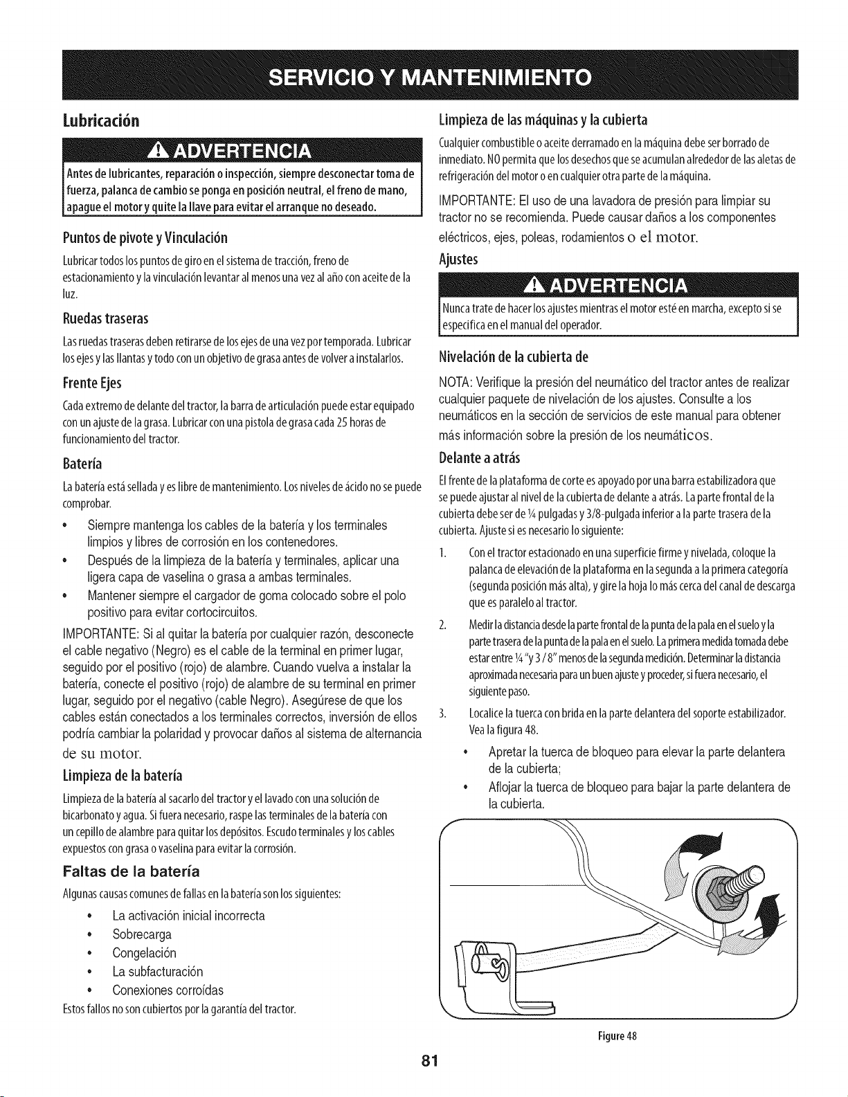
Lubricad6n
Antesde [ubricantes,reparacidno inspecci6n,siempredesconectartoma de
fuerza,palancadecambioseponga en posicidnneutral, el freno de mano,
apagueel motor yquitelaIlave paraevitar el arranquenodeseado.
Puntosde pivote y Vinculad6n
Lubrkartodoslos puntosdegiroenelsistemade tracddn,frenode
estadonamientoy lavinculaddnlevantaralmenosunavezal afroconaceitede la
hz.
Ruedastraseras
Lasruedastraserasdebenretirarsedelosejesde unavezportemporada.Lubrkar
losejesy lasIlantasytodoconunobjetivodegrasaantesdevolvera[nstalarlos.
FrenteEjes
Cadaextremode delantedeltractor,la barradeartkulad6n puedeestarequipado
conunajustede lagrasa.LubrkarconunaNstoladegrasacada25horasde
fundonamientodeltractor.
Bateria
Labateriaest.1se[[adayes[ibredemantenimiento.Losnive[esde_iddonosepuede
comprobar.
• Siempremantengalos cablesde labateriay losterminales
limpiosy libresde corrosidnen los contenedores.
• Despu_sde[a [impiezade [a bateriay terminaies,apiicaruna
[igeracapa de vaseiinaograsaa ambasterminales.
• Mantenersiempreelcargadorde gomaco[ocadosobreel polo
positivoparaevitarcortocircuitos.
IMPORTANTE:Sial quitarla bateriapor cualquierrazdn,desconecte
el cablenegativo(Negro)es elcable de la terminalen primerlugar,
seguidoporel positivo(rojo)de alambre.Cuandovuelvaa instalarla
bateria,conecteel positivo(rojo) de alambrede su terminalen primer
lugar,seguidopor el negativo(cableNegro).AsegQresede que los
cablesestfin conectadosa los terminalescorrectos,inversidnde ellos
podriacambiarla polaridady provocardaffosal sistemade alternancia
de su motor.
Limpieza de la bateda
LimNezade h bateriaa[sacarlodeltractory elhvadoconunasoluddnde
bicarbonatoyagua.S[fueranecesario,raspelasterminalesde labateriacon
uncepiHodealambreparaquitar losdepdsitos.Escudoterminalesy loscables
expuestoscongrasaovaselinaparaevitarlacorrosidn.
Faltas de la bateria
Algunascausascomunesdefallasenlabateriasonlossiguientes:
• Laactivacidninicialincorrecta
• Sobrecarga
• Congelacidn
• La subfacturacidn
• Conexionescorroidas
Estosfallosnosoncubiertosporlagarantiadeltractor.
Limpiezade lasm,iquinas y la cubierta
Cualquiercombustibleoaceitederramadoenla m_iquinadebeserborradode
[nmediato.NOpermitaquelosdesechosqueseacumulanalrededordelasaletasde
refrigeraddndelmotoroencualquierotra partedelam_iquina.
IMPORTANTE:El usode una lavadorade presidnparalimpiarsu
tractorno se recomienda.Puedecausardaffosa los componentes
el_ctricos,ejes,poleas,rodamientoso el motor.
Ajustes
Nuncatrate dehacerlosajustesmientrasel motorest_en marcha,exceptosise
espedficaen elmanualdeloperador.
Nivelad6n de la cubiertade
NOTA:Verifiquela presidndelneum_.ticodeltractorantesde realizar
cualquierpaquetede nivelacidndelos ajustes.Consultea los
neumfiticosenla seccidnde serviciosde este manualparaobtener
milsinformacidnsobrela presidnde los neumfitJcos.
Delantea atr,is
Elfrentedelaplataformadetorte esapoyadoporunabarraestaNlizadoraque
sepuedeajustaral nivelde lacubiertadedelanteaatkis. Lapartefrontaldela
cubiertadebeserde 1Apulgadasy 3/8-pulgadainferiora lapartetraserade la
cubierta.Ajustesi esnecesarioIosiguiente:
1. Conel tractorestadonadoen unasuperfidefirmey Nvelada,coloquela
palancadeelevaddnde laplataformaen la segundaalaprimeracategoria
(segundaposiddnm_isalta),y girela hojaIom_iscercadelcanaldedescarga
queesparaleloal tractor.
2. Medirladistanciadesdelapartefrontaldelapuntadelapalaenelsueloyla
partetraseradelapuntadelapalaenelsuelo.Laprimeramedidatomadadebe
estarentrelg'y 3/8" menosdelasegundamedkidn.Determinarladistanda
aproximadanecesariaparaunbuenajustey proceder,sifueranecesar[o,el
siguientepaso.
3. LocalkelatuercaconbridaenlapartedelanteradelsoporteestaNlizador.
Yealafigura48.
• Apretar la tuerca de bloqueo para elevar la parte delantera
de la cubierta',
• Aflojar la tuerca de bloqueo para bajar la parte delantera de
[a cubierta.
f
Figure48
81
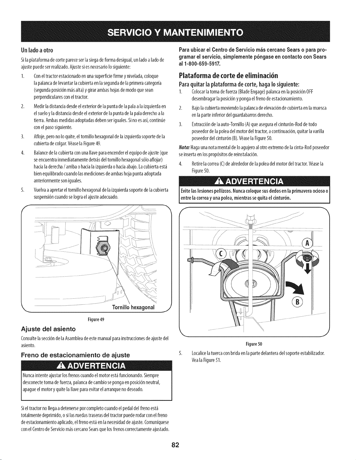
Unladoa otto
Silaplataformadecortepareceserlasiegade formadesigual,un ladoaladode
ajustepuedeserreallzado.Ajustes[esnecesarloIoslguiente:
1. Coneltractorestadonadoenunasuperfidefirme y nivelada,coloque
lapalancade levantarlacubiertaen lasegundadelaprimeracategoria
(segundaposicl6nm_salta)y girar ambashojasdemodoquesean
perpendkularesconeltractor.
2. Medlrladlstandadesdeelexteriordela puntade lapalaa la[zqulerdaen
elsueloy ladistandadesdeelexteriorde lapuntadelapaladerechoa la
tierra.Ambasmedidasadoptadasdebenser[guales.S[noesas[,continue
conel pasosiguiente.
3. Afloje,perono Ioquite,eltornillo hexagonaldela [zquierdasoportedela
cubiertadecolgar.V(_asela Figure49.
4. BalancedelacubiertaconunaIlaveparaencenderelequipodeajuste(que
seencuentra[nmedlatamentedetr_sdel torn[llohexagonals61oaflojar)
hadaladerecha/ambao haciala[zqulerdao hadaabajo.Lacubiertaest_
bienequllibradocuandolasmedlclonesdeambashojapuntaadoptada
anterlormentesonlguales.
5. Vuelvaaapretareltorn[llohexagonaldela izquierdasoportedelacubierta
suspensi6ncuandoselograelajusteadecuado.
Paraubicar el Centrode Serviciom_scercanoSearso para pro-
gramarel servicio,simplementep6ngase en contactocon Sears
al 1-800-659-5917.
Plataformadetorte de eliminad6n
Paraquitar la plataforma de torte, haga Iosiguiente:
I. Colocarlatomade fuerza(BladeEngage)palancaenlaposid6nOFF
desembragarla posici6ny pongaelfrenodeestadonamiento.
2. Bajolacubiertamoviendolapalancade elevaci6nde cubiertaenla muesca
en laparteinferiordelguardabarrosderecho.
3. Extracci6ndelaauto-TornilloCA)queasegurael dntur6n-Roddetodo
poseedordelapoleadelmotordel tractor,acontinuaci6n,quitar la varilla
poseedordeldntur6n(B).V6asela Figure50.
Nora: Hagaunanotamentalde Ioagujeroalotro extremodeladnta-Rodposeedor
se[nsertaenlosprop6sitosde reJnstalad6n.
4. Retirelacorrea(C)de alrededorde lapoleadel motordeltractor.V_asela
Figure50.
Evitelaslesionespellizcos.Nuncacoloquesusdedosen la primaveraodoso o
entre la correay unapolea,mientrassequitael cintur6n.
Tornillo hexagonal
Figure49
Ajuste del asiento
Consultelasecd6nde laAsambleadeestemanualparalnstrucdonesdeajustedel
aslento.
Freno de estacionarniento de ajuste
Nuncaintenteajustarlosfrenoscuandoel motorest_funcionando.Siempre
desconectetomadefuerza,palancadecamb[osepongaenposki6nneutral,
apagueel motoryquitelaIlaveparaevitarel arranquenodeseado.
Figure50
Localkelatuercaconbridaenlapartedelanteradelsoporteestabilizador.
Veala Figure51.
SieltractornoIlegaadetenerseporcompletocuandoelpedaldel frenoest_
totalmentedeprimido,osi lasruedastraserasdeltractorpuederodarconelfreno
deestacionamientoaplicado,elfrenoest_enlanecesidadde ajuste.Comun[quese
conel Centrode Serviciom_scercanoSearsquelosfrenoscorrectamenteajustado.
82
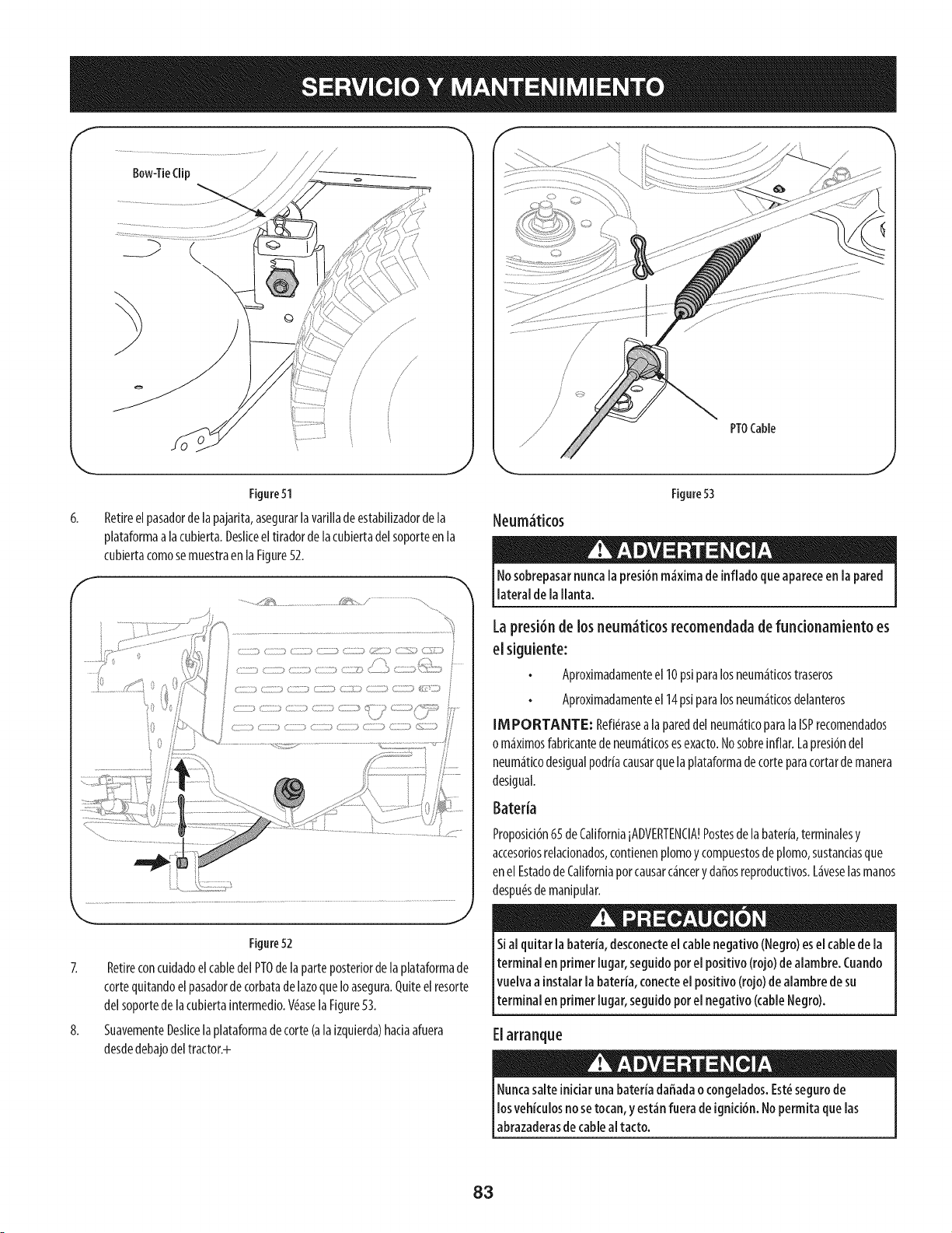
f
6,
F
8,
J
Figure51
Retireel pasadorde lapajarita,asegurarla varillade estabilizadorde la
plataformaalacubierta.Desliceeltiradorde lacubiertadelsoporteen la
cubiertacomosemuestraen laFigure52.
::,2
I _ZZ%:; ( _ ZZZZ;7 ¢:ZZZ_,) 'Z2£M ZZZ.; _
ZZZ2 ( Z_ZI3
Figure52
Retireconcuidadoelcabledel PTOdelaparteposteriordela plataformade
torte quitandoelpasadorde corbatadelazoqueIo asegura.Quiteelresorte
delsoportede lacubiertaintermedio.V(_asela Figure53.
SuavementeDeslicelaplataformadetorte (ala izquierda)haciaafuera
desdedebajodeltractor.+
/
/
PTOCable
Neum4ticos
Figure53
Nosobrepasarnuncala presi6nm_×imade inflado clueapareceen lapared
lateral de lallanta.
Lapresi6n de los neum_ticos recomendadadefundonamiento es
elsiguiente:
Aproximadamenteel 10psiparalosneum_ticostraseros
Aproximadamenteel 14psiparalosneum_ticosdelanteros
IMPORTANTE: Refi_rasea lapareddelneum_ticoparala ISPrecomendados
o m_ximosfabricantedeneum_ticosesexacto.Nosobreinflar.Lapresi6ndel
neum_ticodesigualpodriacausarquelaplataformadecorteparacortardemanera
desigual.
BaterJa
Proposici6n65deCaliforniaiADVERTENCIA!Postesdela bateria,terminalesy
accesoriosrelacionados,contienenplomoy compuestosdeplomo,sustanciasque
enel Estadode Californiaporcausarc4ncery daffosreproductivos.L4veselasmanos
despu(_sde manipular.
Sial quitar labateria, desconecteel cablenegativo(Negro)esel cablede la
terminalenprimer lugar, seguidoporel positivo(rojo) dealambre. Cuando
vuelvaa instalar la bateria,conecteel positivo (rojo) de alambrede su
terminal en primer lugar, seguidoporel negativo (cableNegro).
Elarranque
Nuncasalteiniciar unabateria daffadao congelados.Est_segurode
losvehiculosno setocan,y est_nfuera de ignici6n.Nopermita que las
abrazaderasde cablealfacto.
83
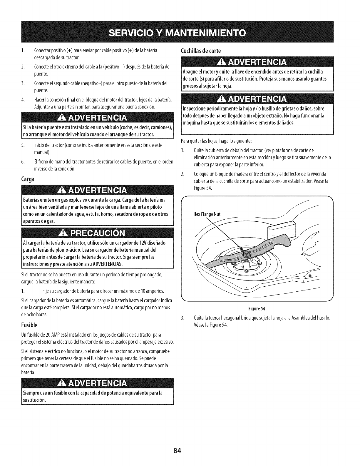
1. Conectarpositivo(+) paraenviarporcablepositivo(+) de labateria
descargadadesutractor.
2. Conecteelotro extremodelcableala(positivo+) despu(_sde labateriade
puente.
3. Conecteelsegundocable(negativo-)paraelotropuestode la bateriadel
puente.
4. Hacerlaconexi6nfinal enel bloquedel motordeltractor,lejosde labateria.
Adjuntara unapartesinpintar,paraasegurarunabuenaconexi6n.
Sila bateria puenteest_[nstaladoen un vebkulo (coche,esdecir,camiones),
no arrangueel motor del vehkulo cuandoelarranguede sutractor.
5. Inidodeltractor(comoseindicaanteriormenteen estasecd6nde este
manual).
6. Elfrenodemanodel tractorantesderetirarloscablesdepuente,enelorden
inversodelaconexi6n.
Carga
Bateriasemiten un gasexplosivodurantela carga.Cargade la bateriaen
un _rea bienventiladay mantenerselejosde unallamaabierta o piloto
comoen uncaientadorde agua,estufa, homo, secadorade ropa odeotros
aparatosdegas.
o
AIcargarla bateriade sutractor, utilke s61oun cargadorde 12Vdiseffado
parabateriasde plomo-_cido.Leasucargadorde bateriamanualdel
Ipropietario antesde cargarlabateria de sutractor. Sigasiemprelas
[instrucdonesy presteatenci6na suADVERTENCIAS.
Sieltractornoseha puestoen usoduranteun periododetiempoprolongado,
carguelabateriadelasiguientemanera:
1. Fijesucargadordebateriaparaofrecerun m&ximode 10amperios.
S[el cargadordela bateriaesautom&tica,carguelabateriahastael cargador[ndica
quelacargaest_completa.Sielcargadornoest&autom&tica,cargoporno menos
deochohoras.
Fusible
Unfusiblede 20AMPest_instaladoenIosjuegosdecablesdesutractorpara
protegerelsistemael(!ctricodeltractorde daffoscausadospotel amperajeexcesivo.
Sielsistemael(!ctrkonofundona,o elmotorde sutractornoarranca,compruebe
primeroquetenet lacertezadequeelfusiblenoseha quemado.Sepuede
encontraren lapartetraserade launidad,debajodelguardabarrossituadaporla
bater[a.
Cuchillas de torte
Apagueel motor yquite laIlavede encendidoantesde retirar lacuchilla
de torte (s)paraafilar o de sustituci6n.Protejasusmanosusandoguantes
lgruesosa sujetar a hoja.
Inspeccioneperi6dicamentelahojay / o husillode grietaso daffos,sobre
todo despu_sde haberIlegadoaunobjeto extraffo. Nohagafuncionar la
m_quinahastaquesesustituir_n loselementosdaffados.
Paraquitarlashojas,hagaIosiguiente:
1. Quitelacubiertadedebajodeltractor,(verplataformadecortede
eliminad6nanteriormenteenestasecd6n)y luegosetira suavementede la
cubiertaparaexporterlaparteinferior.
2. Coloqueun bloquedemaderaentreelcentroy eldeflectordelavivienda
cubiertadelacuchilladecorteparaactuarcomoun estabilizador.Wasela
Figure54.
FlexFlangeNut
Figure54
3. Quitelatuercahexagonalbridaquesujetalahojaa laAsambleadelhusillo.
V_aselaFigure54.
Siempreuseun fusible con la capaddadde potenda equivalente parala
sustituci6n.
84
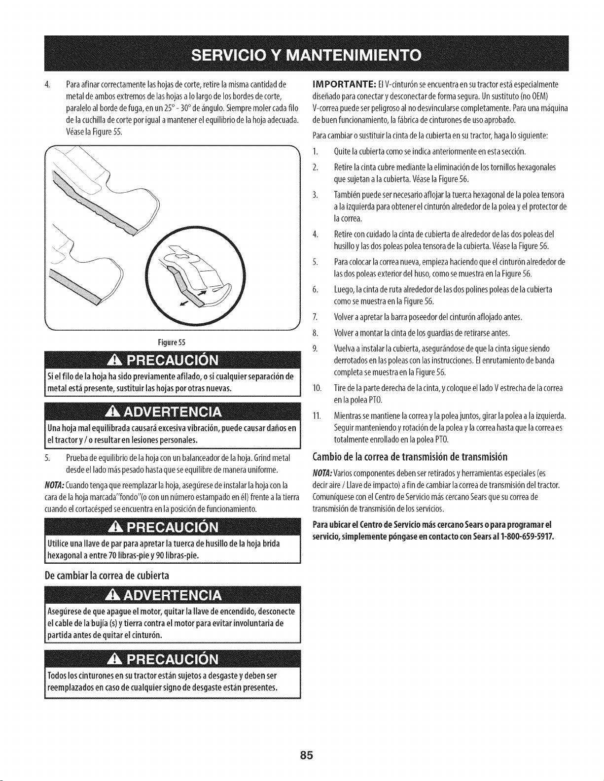
4,
Paraafinarcorrectamentelashojasdecorte,retirelamismacantidadde
metalde ambosextremosdelashojasa Iolargode losbordesdecorte,
paraleloalbordede fuga,en un25° - 30° de_ngulo.Siempremolercadafilo
delacuchilladecorteporigualamantenerelequilibriode lahojaadecuada.
V_asela Figure55.
Figure55
Siel filo de lahoja hasido previamenteafilado, o sicualquierseparaci6nde
metal est_presente,sustituir lashojaspototras nuevas.
Unahojarealequilibradacausar_excesivavibrad6n, puedecausardaffosen
eltractor y I o resultaren lesionespersonales.
5. Pruebade equilibriodelahojaconun balanceadordelahoja.Grindmetal
desdeelladom_spesadohastaqueseequilibrede manerauniforme.
NOTA:Cuandotengaquereemplazarla hoja,aseguresede instalarlahojaconla
carade lahojamarcada"fondo"(oconunnumeroestampadoen _I)frentealatierra
cuandoelcortac_spedseencuentraen laposid6ndefundonamiento.
Utilice unaflare de par paraapretar latuercade husillo de la hojabrida
hexagonala entre 70 libras-piey 90 libras-pie.
[M PORTANTE: ElV-dntur6nseencuentraensutractorest_especialmente
diseffadoparaconectary desconectardeformasegura.Unsustituto(no0EM)
V-correapuedeserpeligrosoal nodesvincularsecompletamente.Paraunam_quina
de buenfuncionamiento,laf_bricadecinturonesde usoaprobado.
Paracambiaro sustituirlacintadelacubiertaen sutractor,hagaIosiguiente:
1. Quitelacubiertacomoseindicaanteriormenteenestasecd6n.
2. Retirelacintacubremediantelaeliminad6nde lostornilloshexagonales
quesujetanalacubierta.V(_aselaFigure56.
3. Tambi(_npuedesernecesarioaflojarlatuercahexagonaldela poleatensora
a laizquierdaparaobtenerelcintur6nalrededordelapoleay elprotectorde
lacorrea.
4. Retireconcuidadoladnta decubiertade alrededorde lasdospoleasdel
husilloy lasdospoleaspoleatensoradelacubierta.V(_asela Figure56.
5. Paracolocarlacorreanueva,empiezahadendoqueel cinturdnalrededorde
lasdospoleasexteriordel huso,comosemuestraenla Figure56.
6. Luego,ladnta derutaalrededordelasdospolinespoleasdela cubierta
comosemuestraen laFigure56.
7. Volveraapretarlabarraposeedordelcinturdnaflojadoantes.
8. Volvera montarlacintadelosguardiasderetirarseantes.
9. Vuelvaainstalarlacubierta,asegur_ndosedequeladnta siguesiendo
derrotadosenlaspoleasconlasinstrucdones.Elenrutamientodebanda
completasemuestraen laFigure56.
10. Tiredelapartederechade lacinta,y coloqueelladoVestrechade lacorrea
en lapoleaPT0.
11. Mientrassemantienelacorreay lapoleajuntos,girar lapoleaa laizquierda.
Seguirmanteniendoy rotad6ndela poleay lacorreahastaquelacorreaes
totalmenteenrolladoenlapoleaPT0.
Cambiode la correa detransmisi6n detransmisi6n
#OTA:Varioscomponentesdebenserretiradosy herramientasespeciales(es
deciraire/ Llavedeimpacto)afin decambiarlacorreadetransmisi6ndeltractor.
Comuniqueseconel CentrodeServiciom_scercanoSearsquesucorreade
transmisidnde transmisi6ndelosservidos.
Paraubicarel CentrodeServidom_s cercanoSearso para programar el
servido, simplemente p6ngaseen contacto conSearsal 1-800-659-5917.
Decambiar la correa decubierta
Aseguresede queapagueel motor, quitarla flare de encendido,desconecte
elcablede labujia (s)ytierra contrael motor para evitar involuntariade
partida antesdequitareldntur6n.
Todosloscinturonesen sutractor est_nsujetosa desgastey debenser
reemplazadosen casode cualquiersignodedesgasteest_npresentes.
85
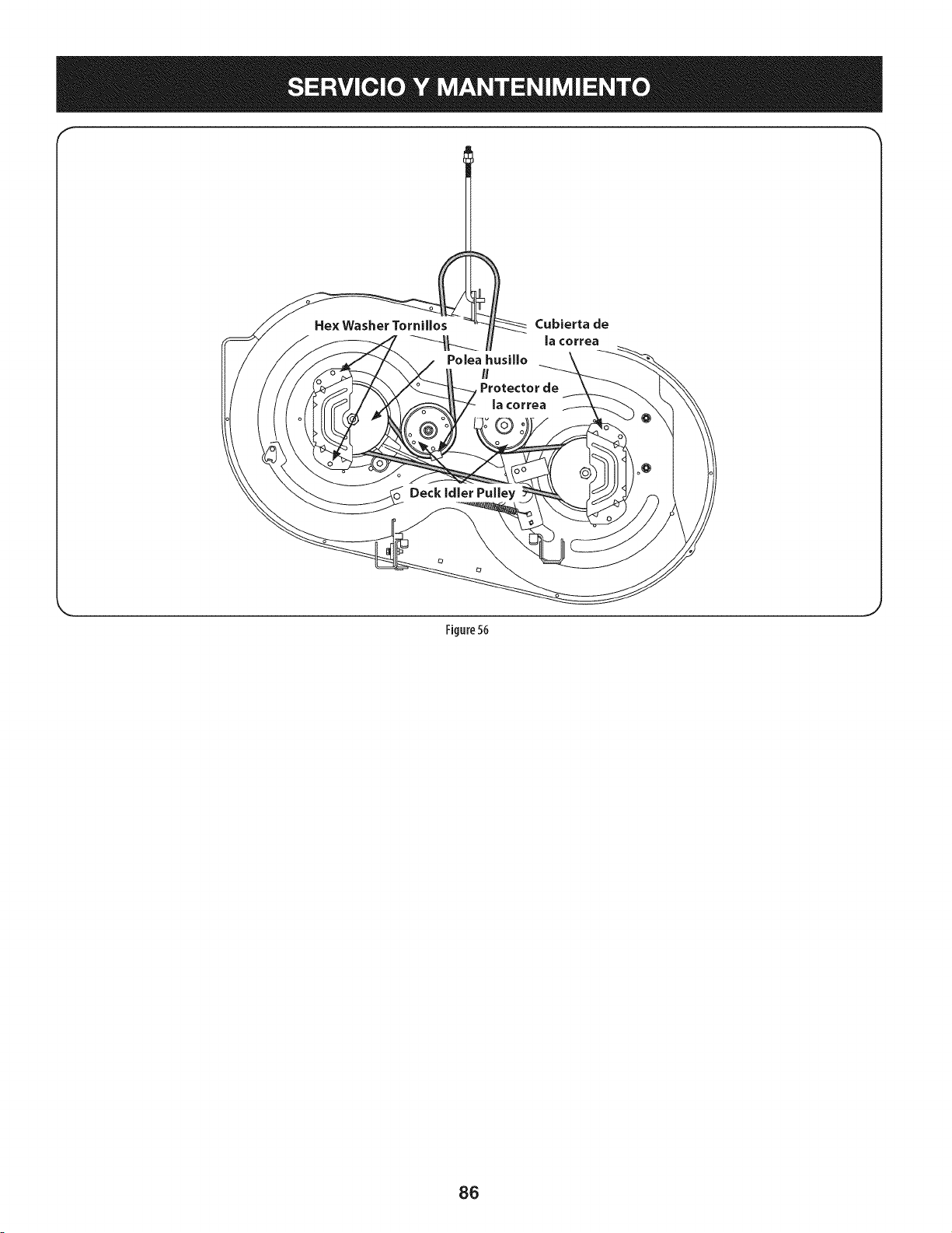
l
Cubierta de
la correa
Figure 56
86
Nuncaalmacenetractor de c_spedcon combustibleen el tanque en un
espaciocerradooen ,_reasconpocaventilaci6n,dondelosgasesdel
combustiblepuedanalcanzarelfuego,chispaso unaluz piloto comolaque
tienen algunoshornos,calentadoresde agua,secadoresde ropaoalgun
otro dispositivoagas.
Preparad6ndeimotor
IM PORTANTE: Elcombustiblequequedaen eltanquecuandohatecalorse
deterioray ocasionagravesproblemasdeencendido.
Panevitarqueseformendep6sitosdegomadentrodel carburadordel motor
y posiblesdesperfectosenel motor,elsistemadecombustibledebeservadado
completamente,o sedebetratarlagasolinaconunestabilizadorparaevitarel
deterioro.
I. Siutilizaunestabilizadordecombustible:
a. Lealasinstrucdonesy recomendadonesdelfabricantedel producto.
b. Agreguelacantidadcorrectadeestabilizadorparalacapaddaddel
sistemadecombustibleagasolinaIimpiay nueva.
c. Lleneeldep6sitodecombustibleconcombustibletratadoyhaga
fundonarelmotor2-3minutosparaestabilizarel combustibledentro
delcarburador.
Cuandovacieelsistemade combustible:
a. Nodreneelcombustiblecuandoelmotorest_caliente.Permitaque
elmotorseenfriebien.Dreneelcombustibledentrodeun redpiente
aprobadoyal airelibre,lejosdecualquierllamaexpuesta.
b. Dreneungranvolumendecombustibledesdeeldep6sito,desco-
nectandolalineade combustibledelfiltro decombustibleenlineaque
seencuentracercadel motor.
Lagasolinaessumamenteinflamabley puedesetexplosivaen dertas
condkiones.Vadela antesdealmacenarel equipoduranteperiodos
prolongados.Dreneel combustiblet_nicamentedentro de un recipiente
aprobadoy al airefibre, lejosde cualquierllamaexpuesta.Dejeque
el motor seenfrie. Antesde drenar el combustible,apaguedgarrillos,
cigarros,pipasyotrasfuentesde combusti6n.Vadelagasolinaen un _rea
bienventilada,lejosdecualquierfuentedellama ochispas,incluidocualquier
artefactoconluzpiloto.Almacenelagasolinaen un redpienteaprobado,en un
lugarseguro.
Extraigalabujiay viertauna(1)onzadeaceiteparamotorporelorifido
delabujiaenelcilindro.Hagagirarel motorvariasvecesparadistribuirel
aceite.Vuelvaacolocarlabujia.
Eldrenaje de loscombustibles
1. Localiceelfiltro decombustible,queseencuentraenel ladoizquierdodel
motor,y puedeserconectadoal motorconunacorreade empate.
2. Cortarla correade la corbata,si est_presente,entoncesemergenteenla
abrazaderaenlineaenel filtro decombustibleconun pardealicates,deslice
laabrazaderadela lineadecombustible.
Quitelalineadecombustibleen lalineayla fugade combustibleenun
redpienteaprobado.
Preparad6nde ia tractor de c sped
1. Limpiey lubriquelatractorcomosedescribeenlasinstrucdonesde
lubricaci6n.
2. Noutiliceunalavadoraapresi6nniunamangueradejard[nparalimpiarsu
unidad.
3. Almacenelatractoren unazonalimpiay seca.Nola almacenecercade
materialescorrosivoscomoporejemplofertilizantes.
c. Vuelvaacontectarlalineadecombustibley hagafundonarel motor
hastaquecomiencea fallar,useentoncesel cebadorparamantenerel
motoren marchahastaagotartodoel combustibledelcarburador.
d. VuelvaadesconectarlaI[neadecombustibley drenelagasolina
restanteenelsistema.
Lagasolinaesunasustandat6xica.Elimine lagasolinaadecuadamente.
Comuniqueseconlasautofidadeslocalespara averiguarcuries sonlos
_todosadecuadospara eliminar lagasolina.
87
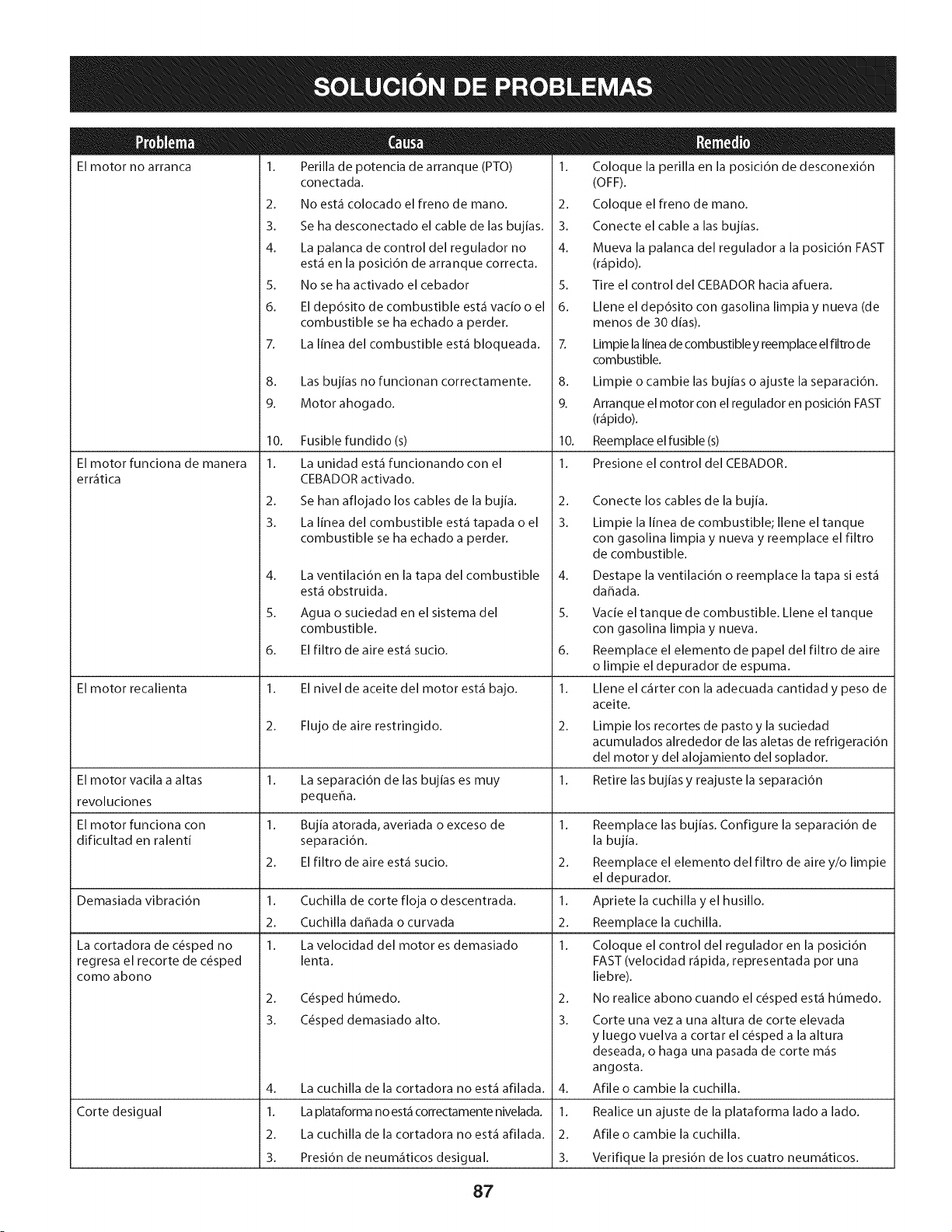
El motor no arranca
El motor funciona de manera
err_tica
El motor recalienta
1. Perilla de potencia de arranque (PTO)
conectada.
2. No est.1 colocado el freno de mano.
3. Se ha desconectado el cable de las bujias.
4. La palanca de control del regulador no
est.1 en la posici6n de arranque correcta.
5. No se ha activado el cebador
6. El dep6sito de combustible est.1 vacio o el
combustible se ha echado a perder.
7. La linea del combustible est.1 bloqueada.
8. Las bujias no funcionan correctamente.
9. Motor ahogado.
10. Fusible fundido (s)
1. La unidad est,1 funcionando con el
CEBADOR activado.
2. Se han aflojado los cables de la bujia.
3. La linea del combustible est,1 tapada o el
combustible se ha echado a perder.
4.
5.
6.
La cortadora de c6sped no
regresa el recorte de c6sped
como abono
La ventilaci6n en la tapa del combustible
est,1 obstruida.
Agua o suciedad en el sistema del
combustible.
El filtro de aire est,1 sucio.
1. El nivel de aceite del motor est,1 bajo.
2. Flujo de aire restringido.
1. Coloque la perilla en la posicidn de desconexidn
(OFF).
2. Coloque el freno de mano.
3. Conecte el cable a las bujias.
4. Mueva la palanca del regulador a la posici6n FAST
(r_ipido).
5. Tire el control del CEBADOR hacia afuera.
6. Llene el dep6sito con gasolina limpia y nueva (de
menos de 30 dias).
7. Limpie la linea de combustible y reemplace el filtro de
combustible.
8. Limpie o cambie las bujias o ajuste la separaci6n.
9. Arranque el motor con el regulador en posici6n FAST
(r_ipido).
10. Reemplace el fusible (s)
1. Presione el control del CEBADOR.
2.
3.
El motor vacila a altas 1. La separaci6n de las bujias es muy 1.
revoluciones pequer_a.
El motor funciona con 1. Bujia atorada, averiada o exceso de 1.
dificultad en ralenti separacidn.
2. El filtro de aire est,1 sucio. 2.
Demasiada vibracidn 1. Cuchilla de corte floja o descentrada. 1.
2. Cuchilla dahada o curvada 2.
1. La velocidad del motor es demasiado 1.
lenta.
Corte desigual
2. C6sped humedo.
3. C6sped demasiado alto.
Conecte los cables de la bujia.
Limpie la linea de combustible; Ilene el tanque
con gasolina limpia y nueva y reemplace el filtro
de combustible.
4. La cuchilla de la cortadora no est.1 afilada.
1. La plataforma no est.1 correctamente nivelada.
2. La cuchilla de la cortadora no est.1 afilada.
3. Presi6n de neum_iticos desigual.
Destape la ventilaci6n o reemplace la tapa si est,1
dahada.
5. Vacie el tanque de combustible. Llene el tanque
con gasolina limpia y nueva.
6. Reemplace el elemento de papel del filtro de aire
o limpie el depurador de espuma.
1. Llene el c_irter con la adecuada cantidad y peso de
aceite.
2.
3.
Limpie los recortes de pasto y la suciedad
acumulados alrededor de las aletas de refrigeraci6n
del motor y del alojamiento del soplador.
Retire las bujias y reajuste la separaci6n
4.
1.
2.
3.
Reemplace las bujias. Configure la separacidn de
la bujia.
Reemplace el elemento del filtro de aire y/o limpie
el depurador.
Apriete la cuchilla y el husillo.
Reemplace la cuchilla.
Coloque el control del regulador en la posicidn
FAST (velocidad r_ipida, representada pot una
liebre).
No realice abono cuando el c_sped est,1 humedo.
Corte una vez a una altura de corte elevada
y luego vuelva a cortar el c_sped a la altura
deseada, o haga una pasada de corte m_is
angosta.
Afile o cambie la cuchilla.
Realice un ajuste de la plataforma lado a lado.
Afile o cambie la cuchilla.
Verifique la presi6n de los cuatro neum_iticos.
87

Estapagina se dej6 intencionalmente en blanco. Utilice esta pagina para tomar notas acerca de su tractor.
89

Esta pagina se dej6 intencionalmente en blanco. Utilice esta pagina para tomar notas acerca de su tractor.
9O
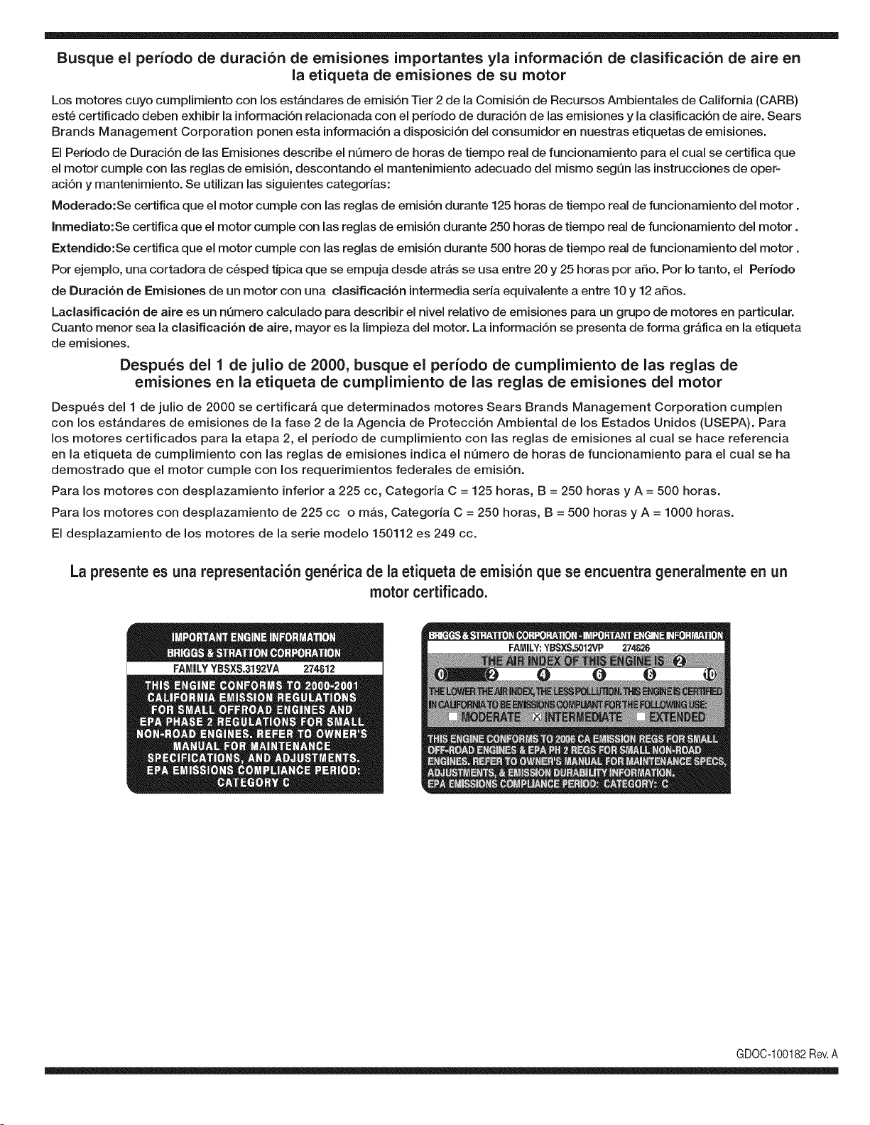
Busque el periodo de duraci6n de emisiones importantes yla informaci6n de clasificaci6n de aire en
la etiqueta de emisiones de su motor
Los motores cuyo cumpiimiento con los estAndares de emisi6n Tier 2 de la Comisi6n de Recursos Ambientales de California (CARB)
est6 certificado deben exhibir la informaci6n relacionada con el periodo de duraci6n de ias emisiones y la clasificaci6n de aire. Sears
Brands Management Corporation ponen esta informaci6n a disposici6n del consumidor en nuestras etiquetas de emisiones.
Ei Periodo de Duraci6n de las Emisiones describe el nQmero de horas de tiempo real de funcionamiento para el cuai se certifica que
el motor cumpie con ias reglas de emisi6n, descontando el mantenimiento adecuado del mismo segQn las instrucciones de oper-
aci6n y mantenimiento. Se utilizan las siguientes categonas:
Moderado:Se certifica que el motor cumpie con las reglas de emisi6n durante 125 horas de tiempo real de funcionamiento del motor.
Inmediato:Se certifica que el motor cumpie con las reglas de emisi6n durante 250 horas de tiempo real de funcionamiento del motor.
Extendido:Se certifica que el motor cumpie con las reglas de emisi6n durante 500 horas de tiempo real de funcionamiento del motor.
Por ejemplo, una cortadora de c6sped tJpica que se empuja desde arras se usa entre 20 y 25 horas por aSo. Por Io tanto, el Periodo
de Duraci6n de Emisiones de un motor con una clasificaci6n intermedia sena equivaiente a entre 10 y 12 aSos.
Laciasificaci6n de aire es un nQmero calculado para describir el nivel relativo de emisiones para un grupo de motores en particular.
Cuanto menor sea la clasificaci6n de aire, mayor es la limpieza del motor. La informaci6n se presenta de forma grAfica en la etiqueta
de emisiones.
Despu_s del 1 de julio de 2000, busque el periodo de cumplimiento de las reglas de
emisiones en la etiqueta de cumplimiento de las reglas de emisiones del motor
Despu6s del 1 de julio de 2000 se certificarA que determinados motores Sears Brands Management Corporation cumplen
con los estAndares de emisiones de la fase 2 de la Agencia de Protecci6n Ambientai de los Estados Unidos (USEPA). Para
los motores certificados para la etapa 2, el periodo de cumplimiento con ias reglas de emisiones al cual se hace referencia
en la etiqueta de cumplimiento con las reglas de emisiones indica el nQmero de horas de funcionamiento para el cual se ha
demostrado que el motor cumple con los requerimientos federales de emisi6n.
Para los motores con desplazamiento inferior a 225 cc, Categoria C = 125 horas, B = 250 horas y A = 500 horas.
Para los motores con desplazamiento de 225 cc o mAs, Categoria C = 250 horas, B = 500 horas y A = 1000 horas.
El desplazamiento de los motores de la serie modelo 150112 es 249 cc.
La presente es una representaci6n gen_rica de la etiqueta de emisi6n que se encuentra generaimente en un
motor certificado.
FAMILYYBSXS.3192VA 274812
GDOC-100182Rev.A
(Estap_.ginaseaplicas61oenEE.UU.yCanada.).
SearsBrandsManagement Corporation, el Consejo de Recursos Ambientales de California (CARB)
y la Agencia de Protecci6n Ambiental de los Estados Unidos (EPA)
Declaraci6n de garantia del sistema de control de emisiones (derechos y obligaciones de la garanfia de defectos del propi=
etario)
LA COBERTURADE LA GARANTJADECONTROLDEEMISIONESES Y PARALOSMODELOSCERTIFICADOSDELANO 1997YPOSTERIORES,
APLIOABLEA LOS MOTORESCERTIFICADOSCOMPRADOSENCALIFOR- QUESE COMPRENY UTILICENEN CUALQUIERPARTEDE LOS ESTADOS
NIA EN1995Y POSTERIORMENTE,QUESE UTILIZANENCALIFORNIA, UNIDOS(Y A PARTIRDEL 1 DE ENERODE2001 ENCANADA).
Declaraci6n de garanfia sobre defectos en el control de emisiones para California y los Estados Unidos
ElConsejode RecursosAmbientalesde California(CARB),la EPA(Agencia
de Protecci6nAmbientalde los EE.UU.)y Searstienenel gusto de explicarla
garantiadel sistemade control de emisionespara motoresdela_o 2000y para
elfuturo con relaci6na motorespeque_ostodo terreno(SORE).En California,
los nuevosmotorespeque_ostodo terrenodebenestar dise_ados,construidos
y equipadosparacumplircon las rigurosasnormasanti-smogdelestado.En
el restode los EstadosUnidos,losmotoresnuevostodoterrenode encendido
porchispa certificadosparael a_o 1997debencumplirest_ndaressimilares
establecidospot la EPA.Searsdebegarantizarel sistemade control de emis-
ionesde su motorparalosperiodosde tiempoenumeradosa continuaci6n,
siemprequeno hayaabuso,negligenciao mantenimientoindebidode su
motortodoterrenopeque_o.Su sistemade controlde emisionespuedeincluir
piezastalescomoel carburador,el filtro de aire, elsistemade encendido,el
silenciadoryel conversorcatalitico.Tambienpuedeincluirconectoresy otras
unidadesrelacionadascon lasemisiones.Dondeexistaunacondici6ncubierta
por la garantia,Searsreparar_su peque6omotortodo terrenosin costo alguno
incluyendodiagn6stico,piezasy manodeobra
Cobertura de la garantJa Sears para defectos en el control de emJsiones
Los motorestodo terrenopeque6osest_ngarantizadosen Io relativoalcontrol alas disposicionesque se indiquena continuaci6n.Si una partede su motor
de emisionesparadefectosenpiezasduranteun periodode dos a_os,sujeto cubiertapot lagaranfiaes defectuosa,Sears reparar_o sustituir_dicha parte.
Responsabilidades del propietario en relacibn con la garantia
Comopropietariodel motortodo terrenopeque_o,Ud.es responsablede la
realizaci6ndel mantenimientorequeridoquese incluyeen las instrucciones
de operaci6ny mantenimiento.Searsrecomiendaquese conserventodoslos
recibosrelativosal mantenimientode su motortodoterrenopeque_o,pero
no pude denegarla garantiasimplementepor la faltade los mismos,o por su
incumplimientodel mantenimientoprogramatic.Comopropietariodel motor
peque_otodoterrenodebe saberque, sinembargo,Sears lepuedenegar
lacoberturade lagarantiasi su motortodoterrenopeque6oouna piezadel
mismohanfalladodebidoa abuso,negligencia,mantenimientoindebidoo
a modificacionesno aprobadas.Ud.es responsablede presentarsu motor
todoterrenopeque6oa un distribuidorde serviciosSearsautorizadotan pronto
comoaparezcaun problema.Las reparacionesde la garantiasinconfiicto
debencompletarseen un plazode tiempo razonable,no superiora 30 dias.Si
tienealgunapreguntarespectoa sus derechosy responsabilidadesreferen-
tes a la garantia,debe contactarcon un representantede serviciosSearsal
1--800--469--4663.La garantiade emisioneses unagarantiapor defectos.Los
defectosse juzgande acuerdocon elfuncionamientonormalde un motor.La
garantiano est_relacionadacon unapruebade emisionesen uso.
Disposiciones de la garantJa Sears para defectos en el control de emJsiones
Las siguientesson disposicionesespecificasrelacionadascon la coberturade lagarantia paradefectosenel controlde emisiones.Esun a_adidoa lagarantiade
motorSearspara motoresno reguladosque seencuentraen lasinstruccionesde funcionamientoy mantenimiento.
1. Piezascon garantia
La coberturade esta garantiase extiendeL]nicamentea laspiezas
queaparecena continuaci6n(las partesde lossistemasde controlde
emisiones),siempreque dichas piezasestuvieranya en el motoren el
momentode su compra.
a. Sistemade medici6n de combustible
• Sistema de enriquecimientopara arranqueen frio
• Carburadory partesinternas
• Bombade combustible
b. Sistemade inducci6nde aire
• Filtrode aire
• Colector de admisi6n
c. Sistemadeencendido
• Bujia(s)de encendido
• Sistema de encendidomagneto
d. Sistemadelcatalizador
• Convertidorcatalitico
• Colector de escape
• Sistema de inyecci6nde aireo v_lvulade impulsos
e. Elementosvariadosusadosen lossistemasanteriores
• Wlvulas de vacio,sensiblesa temperatura,posici6ny tiempo
e interruptores
• Conectoresy montajes
2. AIcancede la cobertura
Searsgarantizaal poseedorinicialy a loscompradoressubsiguientes
quelas piezascon garantiano tendr_ndefectosen materialesni mano
de obra que provoquenla falla de las mismasduranteun periodode
dos aSosa partirde la fechaen queel motorse entregaa un comprador
particular.
3. Sin cargo
La reparaci6no reemplazodecualquierpartecon garantia se realizar_
sin cargo alguno parael poseedor,incluyendotareasde diagn6sticoque
permitandeterminarsi una partecon garantiaes defectuosa,siempreque
dichodiagn6sticose realiceen un distribuidorde serviciosSearsautoriza-
do. Parael servicio de lagarantia de emisiones,contacteal distribuidorde
serviciosSearsautorizadom_s cercanoincluidoen las"P_ginasamarillas"
en lascategorias"Motores,gasolina","Motoresde gasolina","Podadoras
de cesped",o similares.
4. Reclamacionesyexclusionesa la cobertura
Las reclamacionesde lagarantia debenenviarsede acuerdocon las
disposicionesde la politica de garantia para motoresSears. La cobertura
de lagarantia excluir_defectosen piezascon garantia queno scan partes
originalesSears,o abuso,negligenciao mantenimientoincorrecto,tal y
como se estableceen lapolitica de garantia para motoresSears.Sears no
es responsablede lasfallas en piezascon garantia provocadaspor el uso
de partesa6adidas,que no scan originaleso quese hayan modificado.
5. Mantenimiento
Cualquierpartecon garantiaque no esteprogramadaparaser reem-
plazadacomomantenimientorequerido,o que s61odebainspeccionarse
regularmentealefecto de "inspeccioneo reemplacesegL]nsea necesario",
estar_garantizadacontradefectosduranteel periodode la garantia.Todas
las piezasgarantizadasqueesten programadaspara su reemplazopara
cumplir con los requisitosdemantenimientoestar_ngarantizadass61o
por el periodoanterior al primerreemplazoprogramaticparadicha pieza.
Cualquierpiezade recambioquesea equivalenteen funcionamientoy
durabilidadpuedeusarsepara realizarmantenimientoo reparaciones.El
propietarioes responsablede realizartodoel mantenimientorequerido,tal
y comose define en las instruccionesde funcionamientoy mantenimiento
Sears
6. Coberturaindirecta
Porla presente,la coberturase extiendea la falla de cualquiercomponente
de motorprovocadapot lafalla de unapieza con garantiaque estetodavia
en periodode garantia.
En los EstadosUnidosy Canad_hay unalinea de atenci6nde 24 horas,1-800-469--4GG3,quecuentacon unmenL]con mensajespre-grabadosque contienen
informaci6npara el mantenimientode motores.
DECLARACIONFEDERALy/oDECALIFORNIASOBRE GARANTJAS EN EL CONTROL DE EIVIISIONES
SUS DERECHOS Y OBLIGACIONES EN CUANTO A LA GARANTJA
MTDConsumerGroupInc, laAgencia de Protecci6nMedioambientalde los EstadosUnidos(EPA),y para aquellosproductoscertificadosparasu ventaen el es-
tadode California,el Departamentode los Recursosdel Aire de California(CARB)secomplacenen explicarla garanfiaque cubre al sistemade control(ECS)de
emisiones(evaporativasy/o de escape)de su equipoy motor(motor de equipos de exteriores)de encendidopot chispa paratodo terreno,peque_o,de exteriores
del a_o2006 y a_osposterioresEn California,losnuevosmotoresde equipos de exterioresdebenestar dise_ados,construidosy equipadospara cumplircon las
estrictasnormasantipoluci6ndel Estado(en otrosestados, los equipos del a_o 1997y modelosposterioresdebenser estar dise_ados,construidosy equipados
para cumplircon las regulacionesde motoresde encendidopor chispapara todoterrenopeque_osde laAgencia de Protecci6nMedioambientalde los Estados
Unidos,(EPA).MTDConsumerGroupInc. debe garantizarel sistemadecontrol de emisiones(ECS) de su motorde equipos de exteriorespot el periodode
tiempo indicadom_s abajo,siemprey cuando no existauso incorrecto,negligenciao mantenimientoinadecuadode dicho motor.
Su ECSpuedeincluir piezastales como el carburador,el sistemade inyecci6nde combustible,el sistemadeencendido,el convertidorcatalitico,losdep6sitos
de combustible,laslineas de combustible,lostaponesde combustible,lasv_lvulas, contenedores,filtros, manguerasde vapor,abrazaderas,conectoresyotros
componentesafinesrelacionadoscon lasemisiones.
Dondeexista unacondici6ncubiertapor la garantia,MTDConsumerGroupInc. reparar_su motorde equiposde exterioressincosto alguno incluyendoel
diagn6stico,las piezasy la manode obra.
COBERTURA DE LA GARANTJA DEL FABRICANTE:
Este sistemade control de emisionesse garantizaporel t@minode dos aSos.Si algunapiezarelacionadacon lasemisionesde su motorde equiposde
exterioreses defectuosa,MTDCONSUMERGROUPINC. reparar_o sustituir_dichapieza.
RESPONSABILIDADES DEL PROPIETARIO SEGUN LA GARANTJA:
En su car_cterde propietariodel motorde equipos de exteriores,usted es responsabledel mantenimientorequeridoquese especificaen el manualdel propieta-
rio.MTDConsumerGroupInc le recomiendaque conservetodos losrecibos quecubrenel mantenimientode su motor,no obstanteIo cual MTDConsumerGroup
Inc no podr_denegarel cumplimientode lagarantia Qnicamentepor lafalta de los recibos.
Comopropietariodel motorde equiposde exteriores,usteddebe saber queMTDConsumerGroupInc. puededenegarlacoberturade lagarantiasi su motoro
unapiezadel mismofallan debido a uso incorrecto,negligencia,mantenimientoindebidoo a modificacionesno aprobadas.
Ustedes responsablede presentarsu motoral centrode distribuci6no serviciotecnico de MTDConsumerGroupInc. tan prontocomo aparezcael problema.Las
reparacionescubiertaspor la garantiase debenIlevara caboen unlapso razonableque no excedade 30 dias. Sitiene alguna preguntarespectode lacobertura
de la garantia, p6ngaseen contactoconel Departamentodel ServicioT@nicode MTDConsumerGroupInc. al telefono1-800-800-7310o pot correoelectr6nico
en http://support.mtdproducts.com
COBERTURA DE LA GARANTJA DE EMISIONES GENERALES:
MTDConsumerGroupIncgarantizaal compradorfinal y a cadacompradorsubsiguienteque el motorde equiposde exteriores:est_ dise_ado,construidoy
equipadode modo de cumplir contodas las regulacionesaplicablesy quese encuentralibre de defectosde materialesy de fabricaci6nque pudierencausarla
falla de una piezagarantizadaidentica,en todos losaspectos materialesa la piezadescriptaen la solicitudde certificaci6nde MTDConsumerGroupInc.
El periodode garantiacomienzaen la fechade entregadel motoral compradorfinal o en lafecha en que la m_quinase pone en funcionamientopot primeravez.
El periodode garantiaes de dosaSos.
Sujetoa ciertas condicionesy exclusionesquese indicana continuaci6n,lagarantia de las piezas relacionadascon lasemisioneses la siguiente:
1. Cualquierpiezagarantizadaque no este programadaparaser reemplazadacomo parte del mantenimientorequeridoen lasinstruccionesescritassuminis-
tradasse garantizaporel periodo de garantiaarriba mencionado.Si la pieza falla duranteel periodo de coberturade lagarantia,la mismaser_ reparada
o reemplazadapor MTDConsumerGroupInc. de acuerdo con el parrafo(4) a continuaci6n.Cualquierpiezareparadao reemplazadasegQnlagaranfia se
garantizar_potel resto del periodode garantia.
2. Cualquierpiezagarantizadaqueeste programadasolamentepara inspecci6nregularen las instruccionesescritassuministradassegarantiza potel periodo
de garantia arribamencionado.Cualquierpiezareparadao reemplazadasegQnla garantiase garantizar_pot el restodel periodo.
3. Cualquierpiezagarantizadaqueeste programadapara reemplazosegQnel mantenimientorequeridode conformidadcon lasinstruccionesescritassuminis-
tradas,se garantizaporel periodode tiempo anteriora laprimerafecha de reemplazoprogramadapara esa pieza.Si la piezafalla antes del primerreemplazo
programatic,la mismaser&reparadao reemplazadapot MTDConsumerGroupInc. de acuerdo con el parrafo(4) a continuaci6n.Cualquierpiezareparadao
reemplazadabajogarantia se garantizar_pot el resto del periodoanterioral primerreemplazoprogramaticpuntualpara esa pieza.
4. La reparaci6no el reemplazode cualquierpiezagarantizadade conformidadcon lasdisposicionesde lagarantia queaquise estipulase deben realizaren un
centrode garantiasin costoalgunopara el propietario.
5. Noobstantelas disposicionesque aqui se estipulan,los servicioso reparacionesbajo garantiase suministrar_nen todos nuestroscentrosde distribuci6nbajo
franquiciade mantenimientopara los motoreso equiposen cuesti6n.
6. El propietariodel motorde equiposdeexterioresno deber_pagarel trabajode diagn6sticodirectamenteasociadocon unapiezagarantizadadefectuosaen
relaci6ncon las emisiones,siemprey cuandodicho trabajode diagn6sticose realiceen un centrocubiertopot lagarantia.
7. MTDConsumerGroupInces responsablepotdaSoscausadosa otros componentesde motoreso equipos derivadosde lafalla bajo garantiade cualquier
piezagarantizada.
8. Durantelatotalidaddelperiododegarantiadelmotoryequipoparatodoterrenoarribamencionado,MTDConsumerGroupIncmantendr_unsuministro
depiezasbajogarantiasuficienteparasatisfacerlademandaesperadadetalespiezas.
9. Cualquierpiezadereemplazosepodr_usarparaelcumplimientodelmantenimientoolasreparacionesbajogarantiaysesuministrar_nsincargopara
elpropietario.Dichousonoreducir_lasobligacionesdegarantiadeMTDConsumerGroupInc.
10.Nosepodr_nusarpiezasadicionalesnimodificadasquenoestenexentasdeacuerdoconelDepartamentodelosRecursosdelAire(AirResourcesBoard).
Elusodecualquierpiezaadicionalomodificadanoexentaporelcompradorfinalser_causaldeinvalidezdelosreclamosbajogaranfia.MTDConsumer
GroupIncnotendr_responsabilidadpotlagarantiadefallasdepiezasgarantizadasquefuerencausadaspotelusodeunapiezaadicionalnoexenta
omodificada.
PIEZAS GARANTIZADAS:
La reparaci6no el reemplazode cualquierpiezagarantizadaquede otto modo pudieseestar cubiertapor lagarantia podr_set excluidade tal coberturade
garantiasi MTDConsumerGroupIncdemuestraqueel motores objeto de uso incorrecto,negligenciao mantenimientoinadecuado,y que tal uso incorrecto,
negligenciao mantenimientoinadecuadofue causa directade la necesidadde reparaci6no reemplazode dicha pieza.NoobstanteIo antedicho,cualquierajuste
de un componentecon un dispositivode limitaci6nde ajusteinstaladoen f_brica y quefuncioneadecuadamente,podr_set cubiertopot la garantia.Adem_s,
la coberturabajoesta garantiase extiendesolo a piezas queestuvieronpresentesen el motory equipotodo terrenoadquiridos.
Est_ncubiertaslas siguientespiezascon garanfia para emisiones(decorresponder):
(1) Sistemade medici6nde combustible
• Sistemade mejorapara inicioen frio (cebadosuave)
• Carburadory piezasinternas(o sistemade inyecci6npot combustible)
• Bombade combustible
• Dep6sitode combustible
(2) Sistemade inducci6nde aire
• Purificadordeaire
• Colectordeadmisi6n
(3) Sistemade encendido
• Bujia(s) deencendido
• Sistemade encendidopot magneto
(4) Sistemade encendido
• Convertidorcatalitico
,, SAI (v_lvula Reed)
(5) Componentesvariosutilizadosen el sistemaanterior
• Wlvulas e interruptoresde vacio,temperatura,posici6nsensiblesal tiempo
• Conectoresy montajes
(6) Controlevaporativo
• Manguerade combustible
• Abrazaderasde la manguerade combustible
• Tap6ndel combustibleatadopot correa
• Cajadecarbono
• Lineas de vapor
GDOC-100223

Felicitaciones por haber realizado una adquisici6n inteligente. El producto Craftsman® que ha
adquirido esta diseSado y fabricado para brindar muchos aSos de funcionamiento confiable. Pero
como todos los productos a veces puede requerir de reparaciones. Es en ese momento cuando el
disponer de un Acuerdo de protecci6n para reparaciones le puede ahorrar dinero y problemas.
A continuaci6n se detallan los puntos incluidos en el Acuerdo:
[] Servicio experto prestado por nuestros 10,000 especialistas en reparaciones profesionales
[] Servicio ilirnitado sin cargo para las piezasy la mano de obra en todas las reparacionescubiertas
[] Reernplazo del producto hasta 1500 d61aressi no es posible reparar el producto cubierto
[] Descuento de 25% del precio normal del servicio y de las piezas relacionadas con el mismo que no esten cubiertas
por el acuerdo; ademas, 25% del precio normal de la verificaci6n de mantenimientopreventivo
[] Ayuda r_pida pot tel_fono - Io IlamamosResoluci6n RApida- el apoyo telef6nico de un Chamusca al representante.
Piense en nosotros como el manual "de un dueSohablador."
Una vez adquirido el Acuerdo, puede programar el servicio con tan s61orealizar una Ilamadatelef6nica. Puede Ilamaren
cualquier momento del dia o de la noche o programar un servicio en linea.
ElAcuerdo de Protecci6nde Reparaci6nes una compra sin riesgo. Si usted anula por alguna raz6n durante el periodo de
garantia de producto, proporcionaremos un reembolso Ileno.O, un reembolso prorrateado en cualquier momentodespues
del periodo de garantia de producto expira, iAdquiera hoy su acuerdode protecci6n para reparaciones!
Se aplican determinadas limitaciones y exclusiones. Para obtener informaciTn adicional y precios en los Estados
Unidos Ilame al 1-800-827-6655.
El *Coverage en Canad_ivaria en algunos articulos. Para detalles Ilenos la Ilamada Chamusca Canad_ien 1-800-
361-8885.
Servicio de instalaci6n de Sears
Si desea solicitar la instalaci6n profesionalde Sears de aparatosdomesticos, dispositivos paraabrir portones, calentado-
res de agua y otros articulos domesticos importantes, en los Estados Unidos o Canada flame al 1-800-4-MY-HOME®.

Riding Equipment
questions or problems?
Satisfaction with your purchase
is our number one concern!
To troubleshoot problems,
get answers to questions, order parts,
or schedule repair service for your
Riding Equipment, call the number below.
Para respuestas a preguntas o problemas,
y ordenar piezas o pedir servicio para la
reparacibn de su equipo, Ilame el nt_mero abajo.
1-800-659-5917
Craftsman Help Line
www.craftsman.com
TM
® Registered Trademark / Trademark of KCD IP, LLC in the United States, or Sears Brands, LLC in other countries
® Marca Registrada / TMMarca de Fabrica de KCD IP, LLC en Estados Unidos, o Sears Brands, LLC in otros paises

