Loading ...
Loading ...
Loading ...
Application Examples
DSO5000P Series Digital Storage Oscilloscope User Manual 52
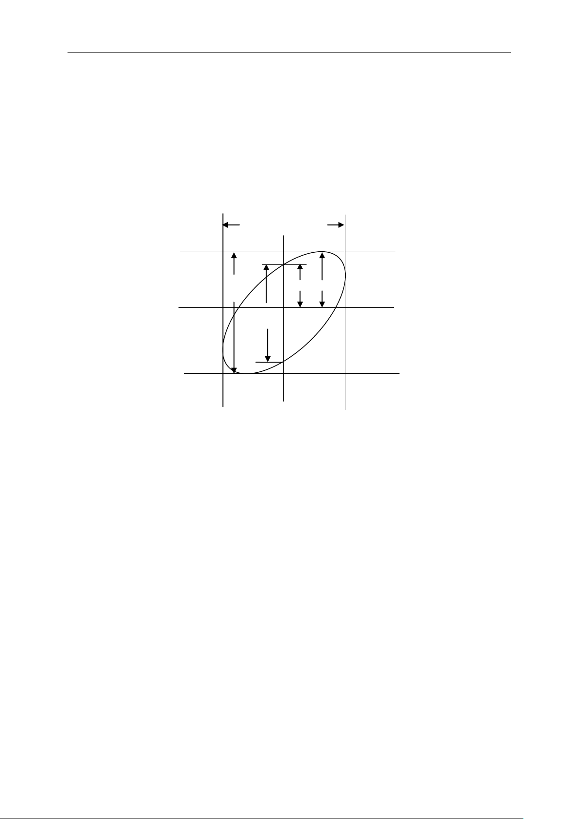
As sinθ=A/B or C/D, in which θ is the phase difference angle between channels and A, B, C, D
represent what shown in the figure below, you can get the value of the phase difference angle by
the formula: θ=±arcsin(A/B) or ±arcsin(C/D).
If the principal axes of the ellipse are in the first and third quadrants, the phase difference angle
should be in the first and fourth quadrants, i.e. within (0~π/2) or (3π/2~2π). If the principal axes of
the ellipse are in the second and fourth quadrants, the phase difference angle should be in the
second and third quadrants, i.e. within (π/2~π) or (π-3π/2). See the figure below for better
understanding.
6.6 Example 6: Triggering on Pulse Width
Triggering on a Specific Pulse Width
While testing the pulse width of a signal in a circuit, you may need to verify the pulse width is
consistent with the theoretic value. Or even if the edge triggering shows that your signal has the
same pulse width with the specific signal, you still doubt about the result. Then you can follow the
steps below.
1. Set the Probe option attenuation to 10X.
2. Push the AUTOSET button to trigger a stable waveform display.
3. Push the Single Cycle option button in the Autoset menu and read out the signal pulse width.
4. Push the TRIG MENU button.
5. Push F1 to select Pulse for the Type option; push F2 to select CH1 for the Source option; turn
the TRIGGER LEVEL knob to set the trigger level at the bottom of the signal.
6. Push F6 to enter the next page. Select the When option button and Push F4 to select ‘=’.
7. Push the Set Pulse Width option button. Turn V0 to set the pulse width to the value read out in
Step 3.
A
B
C
D
Signal Horizontal
Centering
Loading ...
Loading ...
Loading ...