Projector
PA1004UL-W/PA1004UL-B
PA804UL-W/PA804UL-B
Installation Manual
Model No.
NP-PA1004UL-W/NP-PA1004UL-B/NP-PA804UL-W/NP-PA804UL-B

2
Introduction ............................................................................................................................................... 3
Important Information ........................................................................................................................ 4
1. Attachment/detachment of parts sold separately ......................................................... 28
1-1. Lens unit ................................................................................................................................................ 28
1-2. Option cover ........................................................................................................................................ 32
2. Special installation precautions .............................................................................................. 35
2-1. For ceiling installation ..................................................................................................................... 35
2-2. For portrait projection (vertical orientation) ........................................................................... 37
2-3. For multi-Screen projection ........................................................................................................... 40
Table of Contents

3
This manual describes the procedures for installation and connections for the NEC PA1004UL-W/
PA1004UL-B/PA804UL-W/PA804UL-B projector. For safe and correct installation and maintenance of
the projector, carefully read this document before considering the layout of the unit and installation.
Please keep this document under care by the company who installed or adjusted the projector. This
document is intended the readers who have basic knowledge about projector installation. Refer to
the user’s manual of an applicable projector for basic operation and remarks.
NOTE:
• When you use this projector in the United States, please refer to the user's manual for the United States on our website.
https://www.sharp-nec-displays.com/dl/en/pj_manual/pa1004ul.html
• Illustrations and screens shown in this manual may differ slightly from the actual ones.
NOTES
(1) The contents of this user’s manual may not be reprinted in part or whole without permission.
(2) The contents of this user’s manual are subject to change without notice.
(3) Great care has been taken in the preparation of this user’s manual; however, should you notice
any questionable points, errors or omissions, please contact us.
(4) Notwithstanding article (3), NEC will not be responsible for any claims on loss of profit or other
matters deemed to result from using the Projector.
Introduction
4
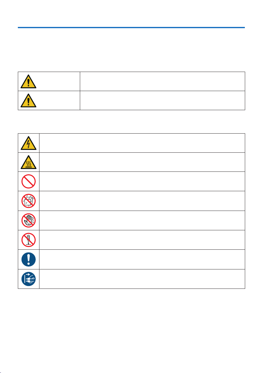
About the symbols
To ensure safe and proper use of the product, this manual uses a number of symbols to prevent
injury to you and others as well as damage to property.
The symbols and their meanings are described below. Be sure to understand them thoroughly
before reading this manual.
WARNING
Failing to heed this symbol and handling the product erroneously
could result in accidents leading to death or major injury.
CAUTION
Failing to heed this symbol and handling the product erroneously
could result in personal injury or damage to surrounding property.
Examples of symbols
This symbol indicates you should be careful of electric shocks.
This symbol indicates you should be careful of high temperatures.
This symbol indicates something that must be prohibited.
This symbol indicates something that must not be got wet.
This symbol indicates you should not touch with wet hands.
This symbol indicates something that must not be disassembled.
This symbol indicates things you must do.
This symbol indicates that the power cord should be unplugged from the power outlet.
Important Information
Important Information
5
Safety Cautions
WARNING
Installing the projector
BE SURE TO DO
• This projector is an RG3 product. The projector is for professional use and
must be installed in location where safety is assured. For this reason, be sure
to consult your dealer as installation and attachment/detachment of the
lens unit must be performed by a professional service personnel. Never try
to install the projector by yourself. This may result in visual impairment etc.
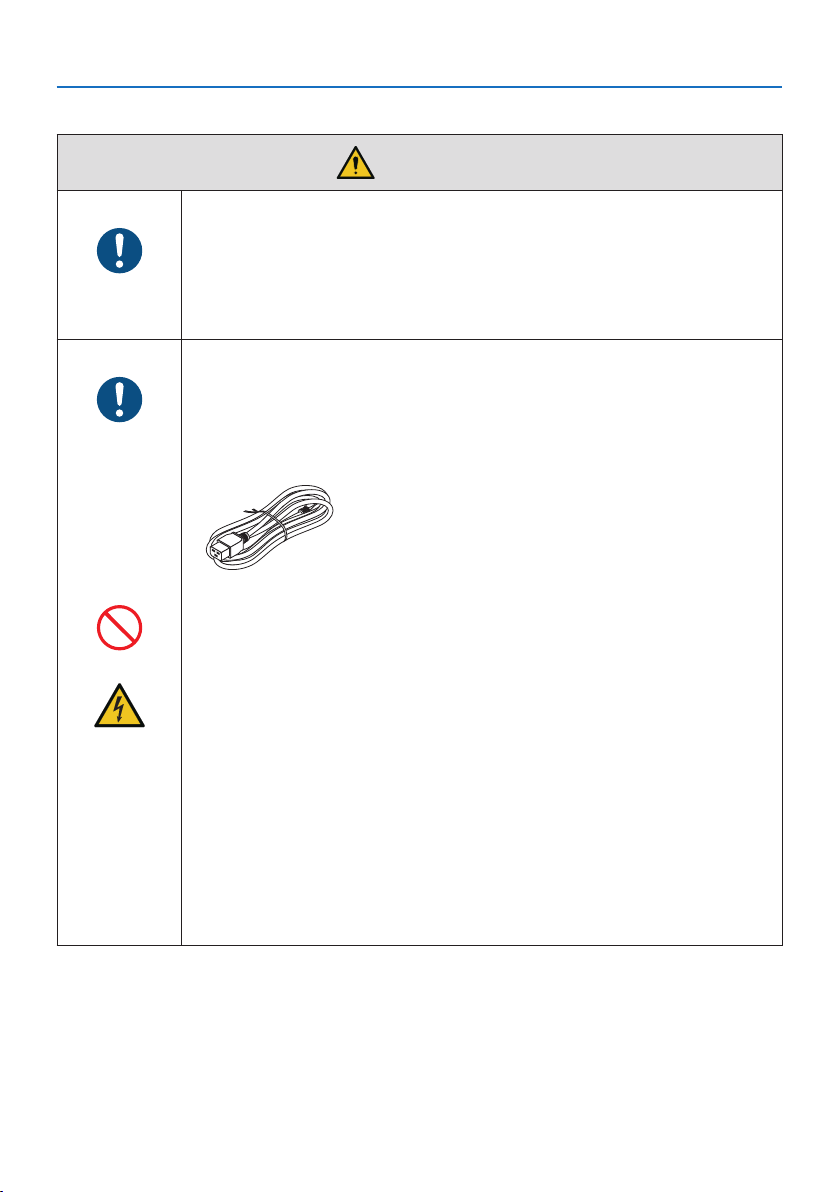
Handling the power cord
BE SURE TO DO
• Please use the power cord supplied with this projector. If the supplied power
cord does not satisfy requirements of your country’s safety standard, and
voltage and current for your region, make sure to use the power cord that
conforms to and satisfies them.
• The power cord you use must be approved by and
comply with the safety standards of your country.
Please refer to the page 184 (User’s Manual) about
the power cord specification.
For selecting an appropriate power cord, please check
rated voltage for your region by yourself.
PROHIBITION
• The power cord included with this projector is exclusively for use with this
projector. For safety, do not use it with other devices.
HAZARDOUS
VOLTAGE
• Handle the power cord with care. Damaging the cord could lead to fire or
electric shock.
- Do not place heavy objects on the cord.
- Do not place the cord under the projector.
- Do not cover the cord with a rug, etc.
- Do not scratch or modify the cord.
- Do not bend, twist or pull the cord with excessive force.
- Do not apply heat to the cord.
Should the cord be damaged (exposed core wires, broken wires, etc.), ask
your dealer to replace it.
• Do not touch the power plug should you hear thunder. Doing so could result
in electric shock.
Important Information
6
WARNING
Installing the Projector
BE SURE TO DO
• This projector is designed to be used with a 100–240 V AC, 50/60 Hz power
supply. Before using the projector, check that the power supply to which the
projector is to be connected meets these requirements.
• Use a power outlet as the projector’s power supply. Do not connect the
projector directly to electrical light wiring. Doing so is dangerous.
• When installing the projector at an angle, the separately sold option cover
may be required for safety depending on the installation angle of the projec-
tor. (→ page 24)
PROHIBITION
• Do not use in places such as those described below. Doing so could lead to
fire or electric shock.
- Shaky tables, inclined surfaces or other unstable places
- Near heating appliances or places with heavy vibrations
- Outdoors or humid or dusty places
- Places exposed to oil smoke or steam
- Near cooking appliances, humidifiers, etc.
DO NOT WET
• Do not use in places such as those described below where the projector could
get wet. Doing so could lead to fire or electric shock.
- Do not use in the rain or snow, on a seashore or waterfront, etc.
- Do not use in a bathroom or shower room.
- Do not place vases or potted plants on the projector.
- Do not place cups, cosmetics or medicines on the projector.
Should water, etc. get inside the projector, first turn off the projector’s power,
then unplug the power cord from the power outlet and contact your dealer.
UNPLUG THE
POWER CORD
• Do not insert or drop metal or combustible objects or other foreign materials
into the projector from the vents. Doing so could lead to fire or electric shock.
Be particularly careful if there are children in the home. Should a foreign object
get inside the projector, first turn off the projector’s power, then unplug the
power cord from the power outlet and contact your dealer.
Unplug the power cord if the projector malfunctions.
UNPLUG THE
POWER CORD
• Should the projector emit smoke or strange odors or sounds, or if the projec-
tor has been dropped or the cabinet broken, turn off the projector’s power,
then unplug the power cord from the power outlet. It may cause not only fire
or electric shock but also serious damage to your eyesight or burns. Contact
your dealer for repairs.
Never try to repair the projector on your own. Doing so is dangerous.
Important Information
7
WARNING
Do not disassemble the projector.
DO NOT
DISASSEMBLE
• Do not remove or open the projector’s cabinet.
Also, do not modify the projector. There are high voltage areas in the projec-
tor. It may cause fire, electric shock, or laser light leakage, resulting in serious
damage to your eyesight or burns.
Have qualified service personnel perform inspection, adjustments and repairs
of the interior.
Installing suspended from the ceiling
CAUTION
• When installed suspended from the ceiling, etc. do not hang from the projec-
tor. The projector could drop and cause injury.
• When installing suspended from the ceiling, use a power outlet that is within
reach so the power cord can be easily plugged and unplugged.
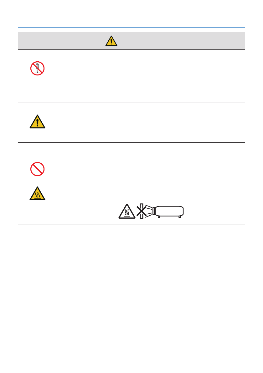
Do not place objects in front of the lens while the projector is
operating.
PROHIBITION
• Do not leave the lens cap on the lens while the projector is operating. The
lens cap could get hot and be warped.
• Do not place objects in front of the lens that obstruct the light while the
projector is operating. The object could get hot and be broken or catch fire.
• The below pictogram indicated on the cabinet means the precaution for
avoiding to place objects in front of the projector lens.
CAUTION
FOR HIGH
TEMPERATURE
Important Information
8
WARNING
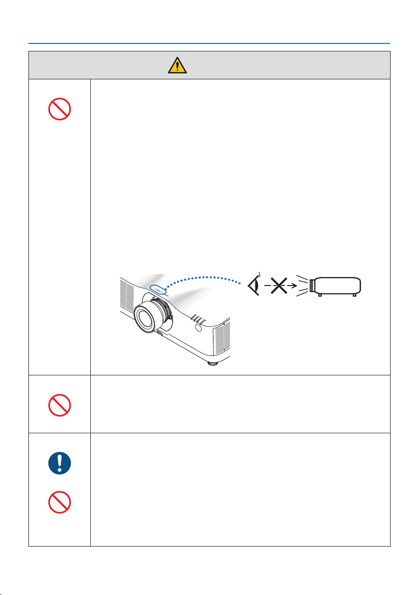
About the projector’s light source
PROHIBITION
• No direct exposure to the beam shall be permitted, RG3 IEC/EN 62471-5:2015.
Operators shall control access to the beam within the hazard distance and
install the product at the height that will prevent exposures of spectators’
eyes within the hazard distance.
• Do not look into the projector’s lens.
Strong light that could damage your eyes is projected when the projector is
operating. Be especially careful when children are around.
• Do not look at the projected light using optical devices (magnifying glasses,
reflectors, etc.). Doing so could result in vision impairment.
• When turning on the power, operate from the side or rear of the projector
(outside the hazard zone). Also, when turning on the power, make sure no
one within the projection range is looking at the lens.
• Do not allow children to operate the projector alone. When a child is operating
the projector an adult should always be present and watch the child carefully.
• The following graphic symbol indicating that looking into the projector is
prohibited is displayed on top of the projector above the lens mounting unit.
When cleaning the projector
PROHIBITION
• Do not use flammable gas sprays to remove dust from the lens, cabinet, etc.
Doing so could lead to fire.
About option cover (separately sold)
BE SURE TO DO
• Be sure to tighten the screws after attaching the option cover. Failure to do so
may cause the cable cover to come off and fall, resulting in injury or damage
to the cable cover.
PROHIBITION
• Do not put bundled cables in the option cover. Doing so may damage the
power cord, resulting in a fire.
• Do not hold the option cover while moving the projector or do not apply
excessive force to the option cover. Doing so may damage the option cover,
resulting in injury.

Important Information
9
CAUTION
Connecting the power cord to earth
BE SURE TO DO
• This equipment is designed to be used in the condition of the power cord
connected to earth. If the power cord is not connected to the earth, it may
cause electric shock. Please make sure the power cord is earthed properly.
Do not use a 2-core plug converter adapter.
Handling the power cord
BE SURE TO DO
• When connecting the power cord to the projector’s AC IN terminal, make sure
the connector is fully and firmly inserted. Be sure to fix the power cord using
the power cord stopper. Loose connection of the power cord could lead to
fire or electric shock.
DO NOT TOUCH
WITH WET
HANDS
• Do not connect or disconnect the power cord with wet hands. Doing so could
result in electric shock.
UNPLUG THE
POWER CORD
• When cleaning the projector, for safety purposes unplug the power cord from
the power outlet beforehand.
• When moving the projector, first be sure to turn off the power, unplug the
power cord from the power outlet and check that all connection cables con-
necting the projector to other devices have been disconnected.
• When planning not to use the projector for long periods of time, always
unplug the power cord from the power outlet.
Do not use on networks subject to overvoltage.
PROHIBITION
• Connect the projector’s Ethernet/HDBaseT port and LAN port to a network
for which there is no risk of overvoltage being applied.
Overvoltage applied to the Ethernet/HDBaseT or LAN port could result in
electric shock.
Lens shift, focus and zoom operations
BE SURE TO DO
• When shifting the lens or adjusting the focus or zoom, do so from either
behind or to the side of the projector. If adjustments are performed from the
front, your eyes could be exposed to strong light and get injured.
• Keep your hands away from the lens area when performing the lens shift op-
eration. If not, your fingers could get caught in the gap between the cabinet
and the lens.
Important Information
10
CAUTION
Handling batteries
PROHIBITION
• Handle batteries with caution. Failure to do so could lead to fire, injury or
contamination of the surroundings.
- Do not short-circuit or take apart batteries or dispose of them in flames.
- Do not use batteries other than those specified.
- Do not use new batteries together with old ones.
- When inserting batteries, pay attention to the polarities (+ and − directions),
and be sure to insert them as indicated.
• Contact your dealer or local authorities when disposing of batteries.
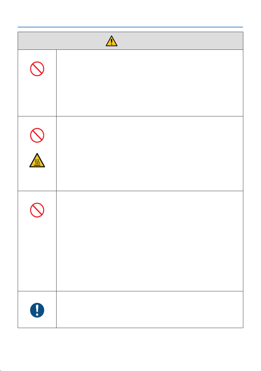
About the vents
PROHIBITION
• Do not obstruct the projector’s vents. Also, do not place such soft objects as
paper or cloths underneath the projector. Doing so could lead to fire.
Leave sufficient space between the place where the projector is installed and
its surroundings. (→ page 27)
• Do not touch the exhaust vent area while projecting or immediately after
projecting images. The exhaust vent area may be hot at this time and touch-
ing it could cause burns.
CAUTION
FOR HIGH
TEMPERATURE
Moving the projector
PROHIBITION
• For moving the projector, make sure you have at least two people. Attempting
to move the projector alone could result in back pain or other injuries.
• When moving the projector, do not hold the lens section. The focus ring
could turn, causing the projector to drop and resulting in injury. Also, if you
put your hand on the gap between the cabinet and the lens, the projector
may be damaged, falling and causing injury.
• When carrying the projector with the lens unit removed, do not touch the
mounting area of the lens with your hands. Also, do not put your hand into
the recess of the connection terminal. The projector could be damaged or
fall down, resulting in injuries.
• When moving the projector with the option cover attached, do not hold it by
the option cover. The option cover could come lose and the main unit could
fall down, causing injuries.
Inspecting the projector and cleaning the inside
BE SURE TO DO
• Consult with your dealer about once per year for cleaning of the inside of the
projector. Dust could accumulate inside of the projector if it is not cleaned
for extended periods of time, leading to fires or malfunction.
Important Information
11
CAUTION
Attaching/detaching the lens
BE SURE TO DO
• Turn off the projector before attaching or detaching the lens unit. Failure to
do so could result in visual impairment. Request your dealer to attach and
detach the lens unit in the no entry area (HD).
Securing the lens unit with the fall prevention wire
BE SURE TO DO
• If the projector is going to be suspended from a ceiling or another high place,
secure the lens unit using the fall prevention wire (sold separately). If the lens
unit is not secured, it may fall down if it comes lose.
About viewing 3D pictures
BE SURE TO DO
• Before viewing, be sure to read health care precautions that may be found in
the user’s manual included with your 3D eyeglasses or your 3D compatible
content such as Blu-ray Discs, video games, computer’s video files and the
like.
• To avoid any adverse symptoms, heed the following:
- Do not use 3D eyeglasses for viewing any material other than 3D images.
- Allow a distance of 2 m/7 feet or greater between the screen and a user.
Viewing 3D images from too close a distance can strain your eyes.
- Avoid viewing 3D images for a prolonged period of time. Take a break of
15 minutes or longer after every hour of viewing.
- If you or any member of your family has a history of light-sensitive seizures,
consult a doctor before viewing 3D images.
- While viewing 3D images, if you get sick such as nausea, dizziness, queasi-
ness, headache, eyestrain, blurry vision, convulsions, and numbness, stop
viewing them. If symptoms still persist, consult a doctor.
• View 3D images from the front of the screen. Viewing from an angle may
cause fatigue or eyestrain.
Important Information
12
Laser Safety Caution
WARNING
CLASS 1 LASER PRODUCT OF IEC 60825-1 THIRD EDITION
• The laser module is equipped in this product. Use of controls or adjustments of procedures
other than those specified herein may result in hazardous radiation exposure.
WARNING
RG3 PRODUCT OF IEC/EN 62471-5 FIRST EDITION
• No direct exposure to the beam shall be permitted, RG3 IEC/EN 62471-5:2015.
• Operators shall control access to the beam within the hazard distance and install the product
at the height that will prevent exposures of spectators’ eyes within the hazard distance.
• This product is classified as Class 1 of IEC 60825-1 Third edition 2014-05 and RG3 of IEC/EN 62471-5
First edition.
Obey the laws and regulations of your country in relation to the installation and management of
the device.
• Outline of laser emitted from the built-in light module:
- Wave length: 455 nm
- Maximum power: 257 W (PA1004UL-W/PA1004UL-B), 229 W (PA804UL-W/PA804UL-B)
• Radiation pattern from the protective housing:
- Wave length: 455 nm
- Maximum laser radiation output: 333 mW
Light Module
• A light module containing multiple laser diodes is equipped in the product as the light source.
• These laser diodes are sealed in the light module. No maintenance or service is required for the
performance of the light module.
• End user is not allowed to replace the light module.
• Contact qualified distributor for light module replacement and further information.
Important Information
13
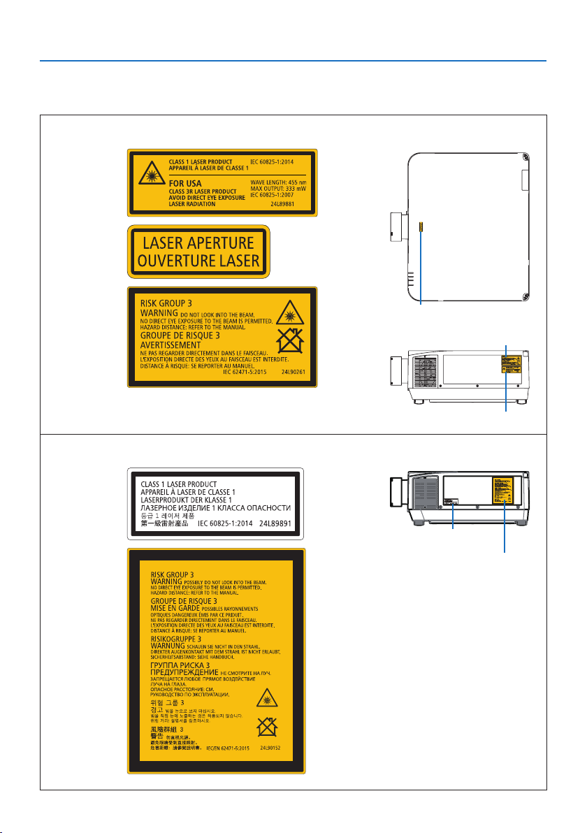
Label Information
The caution and the explanatory labels are stuck on the below indicated positions.
For Canada / South America
Label 1
Label 2
Label 3
Label 1
Label 2
Label 3
For other regions
Label 1
Label 1
Label 2
Label 2
Important Information
14
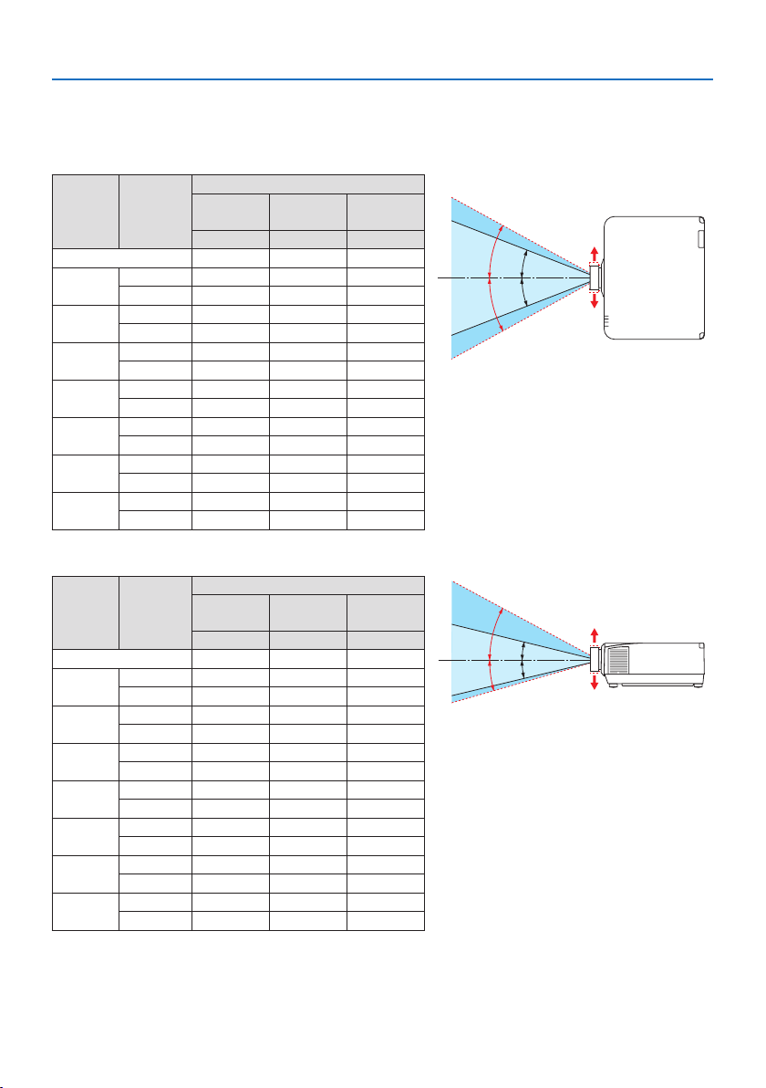
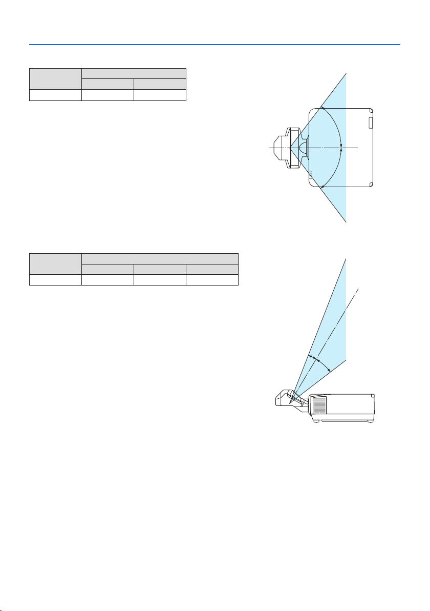
Laser light radiation range
The figure below shows the maximum radiation range of the laser light.
Horizontal angle (unit: degree)
Lens unit Zoom
Lens position
Right most
Center (Refer-
ence value)
Left most
HR HC HL
NP11FL 31.8 31.8 31.8
NP12ZL
Tele 27.4 18.0 27.4
Wide 34.0 22.9 34.0
NP13ZL
Tele 15.1 9.6 15.1
Wide 28.3 18.6 28.3
NP14ZL
Tele 9.6 6.0 9.6
Wide 15.1 9.6 15.1
NP15ZL
Tele 6.4 4.0 6.4
Wide 9.7 6.1 9.7
NP40ZL
Tele 31.7 23.8 31.7
Wide 41.0 31.8 41.0
NP41ZL
Tele 13.0 9.4 13.0
Wide 27.9 20.7 27.9
NP43ZL
Tele 6.8 4.9 6.8
Wide 13.4 9.7 13.4
HC
HR
HL
HC
Left
Right
Vertical angle (unit: degree)
Lens unit Zoom
Lens position
Upper most
Center (Refer-
ence value)
Lower most
VU VC VD
NP11FL 21.2 21.2 21.2
NP12ZL
Tele 24.0 11.5 13.7
Wide 30.1 14.8 17.6
NP13ZL
Tele 13.0 6.0 7.2
Wide 24.8 11.9 14.1
NP14ZL
Tele 8.3 3.8 4.5
Wide 13.1 6.0 7.2
NP15ZL
Tele 5.5 2.5 3.0
Wide 8.4 3.8 4.6
NP40ZL
Tele 28.9 15.4 18.3
Wide 37.8 21.2 24.9
NP41ZL
Tele 11.6 5.9 7.0
Wide 25.3 13.3 15.8
NP43ZL
Tele 6.1 3.0 3.7
Wide 12.0 6.1 7.3
VC
VC
VU
VD
Lower
Upper
Important Information
15
Horizontal angle (unit: degree)
Lens unit
Zoom
Tele Wide
NP44ML
— 55.8
H
H
Vertical angle (unit: degree)
Lens unit
Zoom
Tele V1 V2
NP44ML — 10.7 24.6
V
1
V
2
Important Information
16
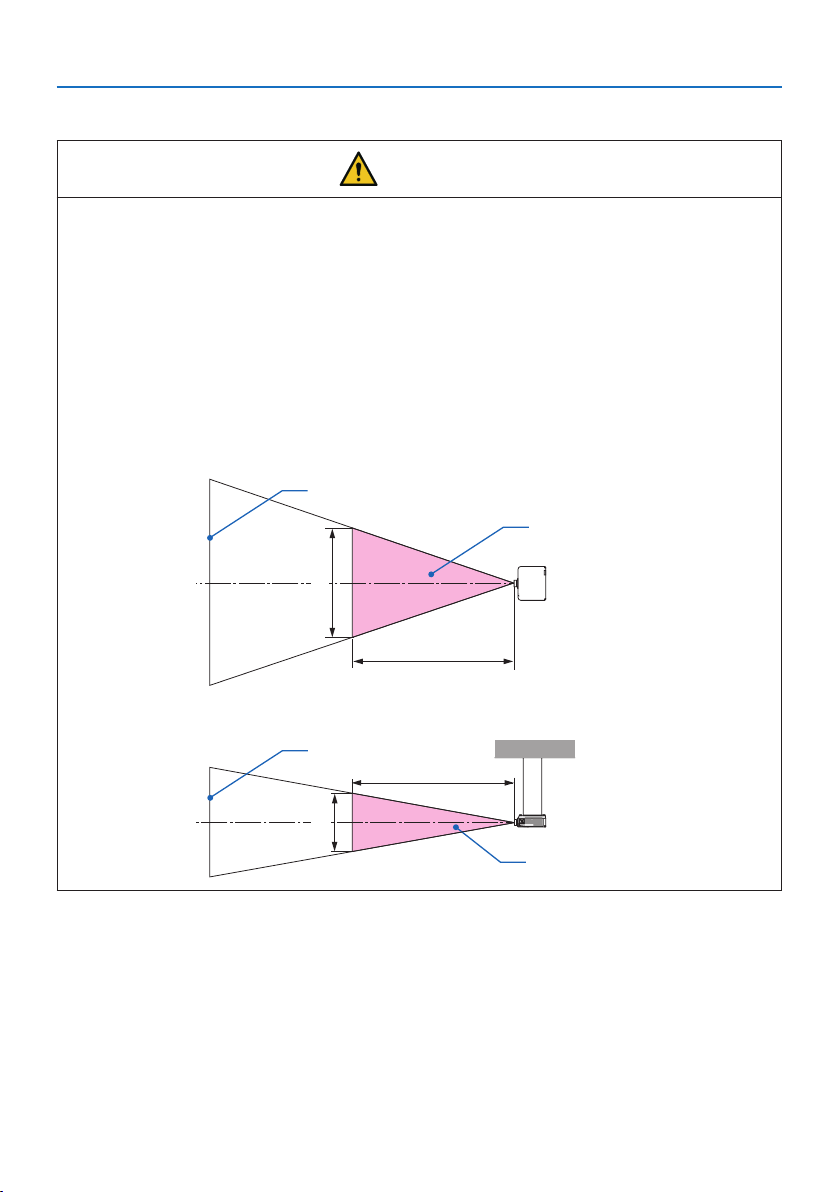
Hazard zone
CAUTION
• The below figure describes the radiation zone (hazard zone) of light emitted by the projector
that is classified as Risk Group 3 (RG3) of IEC/EN 62471-5 First edition 2015.
• Observe the following precautions when installing the projector.
- Install the projector to prevent the eyes of the spectators from being exposed to light in
the hazard zone.
By providing a precautionary zone or physical barriers, it is possible to prevent human eyes
from entering the hazard zone.
- The manager of the projector (operator) must prevent spectators from entering the hazard
zone.
About the hazard zone
Overhead view
Hazard zone
HD
H
Screen
Side view
Hazard zone
HD
V
Screen
About the precautionary zone
When the manager of the projector (operator) cannot prevent spectators from entering the hazard
zone such as in public facilities, it is recommended to secure a space of 1 m or more from the haz-
ard zone as “the precautionary zone” for the safety of the spectators. When installing the projector
overhead, it is recommended that the distance between the floor and the hazard zone be at least
3 m in the vertical direction.
Important Information
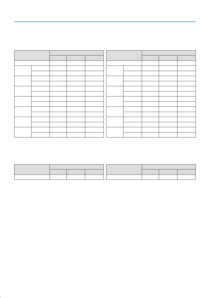
17
Applicable lens: NP11FL/NP12ZL/NP13ZL/NP14ZL/NP15ZL/NP40ZL/NP41ZL/
NP43ZL
PA1004UL-W/PA1004UL-B
Lens
Hazard zone (m)
HD H V
NP11FL 0.3 0.41 0.26
NP12ZL
Wide 0.4 0.38 0.23
Tele 0.5 0.35 0.22
NP13ZL
Wide 0.5 0.37 0.23
Tele 1.5 0.52 0.33
NP14ZL
Wide 1.4 0.51 0.32
Tele 2.5 0.55 0.35
NP15ZL
Wide 2.2 0.51 0.32
Tele 3.1 0.46 0.29
NP40ZL
Wide 0.3 0.42 0.26
Tele 0.5 0.48 0.30
NP41ZL
Wide 0.4 0.34 0.21
Tele 1.5 0.51 0.32
NP43ZL
Wide 1.6 0.51 0.32
Tele 2.9 0.47 0.30
PA804UL-W/PA804UL-B
Lens
Hazard zone (m)
HD H V
NP11FL 0.2 0.29 0.18
NP12ZL
Wide 0.2 0.21 0.13
Tele 0.3 0.22 0.14
NP13ZL
Wide 0.3 0.24 0.15
Tele 1.3 0.45 0.28
NP14ZL
Wide 1.1 0.41 0.26
Tele 2.1 0.47 0.29
NP15ZL
Wide 1.8 0.43 0.27
Tele 2.5 0.38 0.24
NP40ZL
Wide 0.2 0.30 0.19
Tele 0.4 0.39 0.24
NP41ZL
Wide 0.3 0.26 0.16
Tele 1.2 0.41 0.26
NP43ZL
Wide 1.3 0.43 0.27
Tele 2.4 0.39 0.24
Applicable lens: NP44ML
PA1004UL-W/PA1004UL-B
Lens
Hazard zone (m)
HD H V
NP44ML 0.2 0.69 0.43
PA804UL-W/PA804UL-B
Lens
Hazard zone (m)
HD H V
NP44ML 0.2 0.69 0.43
Important Information
18
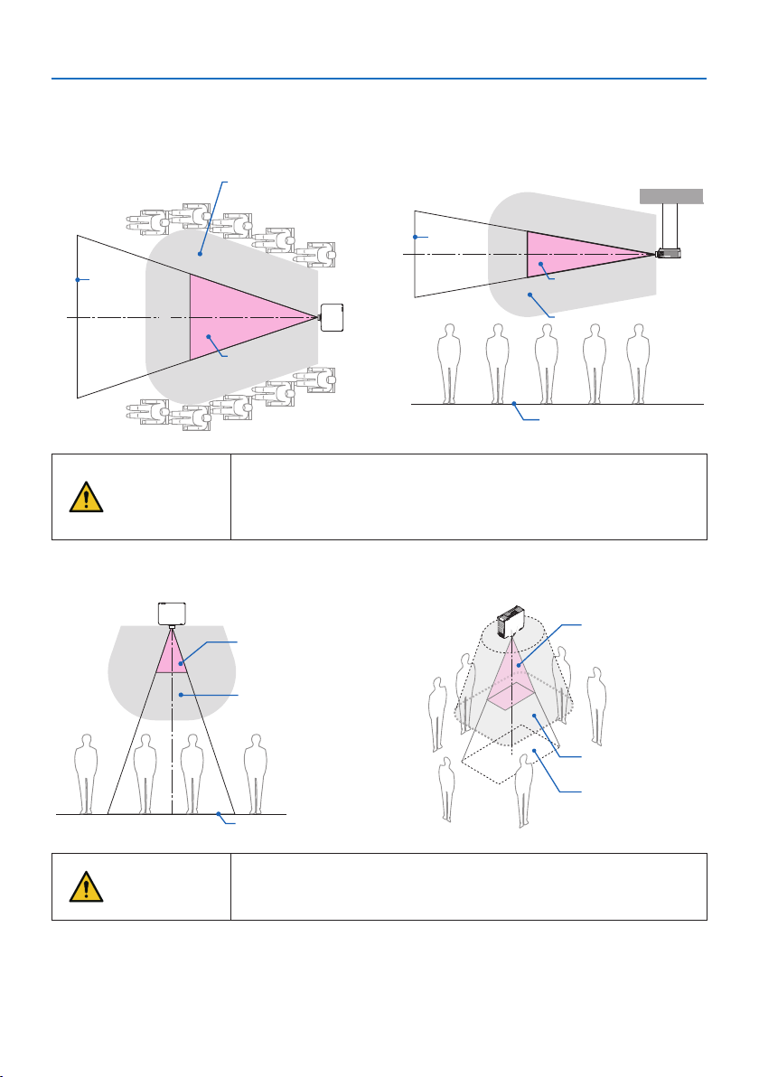
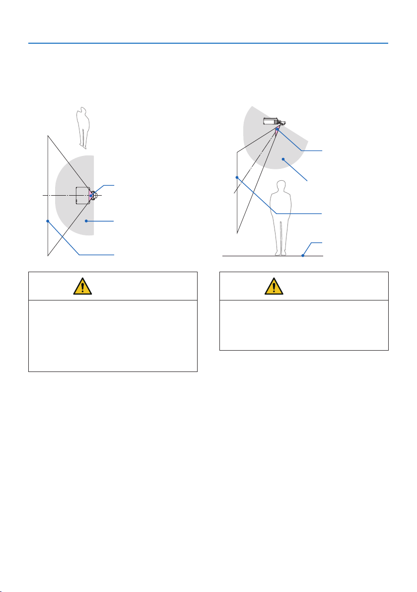
Installation example considering the precautionary zone
(For lens units other than NP44ML)
① Floor or desktop installation example
Hazard zone
Screen
Precautionary zone
② Ceiling installation example
Hazard zone
Screen
Precautionary zone
floor
CAUTION
If it is expected that spectators will intrude into the hazard zone when
installed on the ceiling (for example, if the distance between the floor
and the precautionary zone is 2 m or less), it is necessary to prevent
spectators from entering that area.
③ Example of downward projection installed on the ceiling
Hazard zone
Precautionary zone
floor
Hazard zone
Precautionary zone
floor
CAUTION
If the precautionary zone between the floor and the hazard zone can-
not be secured, it is necessary to prevent spectators from entering the
area around the screen as shown in the figure on the right.
* If using lens shift, please consider the shift of projected image according to the volume of lens shift.Instal-
lation example considering the precautionary zone (For lens units other than NP44ML)
Important Information
19
Installation example considering the precautionary zone
(For NP44ML)
① Floor or desktop installation example
Screen
Hazard zone
Precautionary zone
② Ceiling installation example
Screen
Hazard zone
Precautionary zone
floor
CAUTION
When installing the NP44ML, there is a risk
of intrusion into the hazard zone and the
precautionary zone when operating the
buttons on the projector.
For safety, it is recommended to use the
remote control.
CAUTION
If the precautionary zone cannot be secured
between the floor and the hazard zone,
spectators must be restricted from entering
the space between the projector and screen.
* The above figure is an example of a typical installation. It is also necessary to secure the precautionary zone
when installing the projector at an angle.
Important Information
20
CAUTION
Please follow all safety precautions.
Installing the projector
• This projector is an RG3 product. The projector is for professional use and must be installed in
a location where safety is assured. For this reason, be sure to consult your dealer as installation
and attachment/detachment of the lens unit must be performed by a professional service
personnel. Never try to install the projector by yourself. This may result in visual impairment,
etc.
• When planning the layout of the projector, make sure to follow the safety measures listed in
the installation manual.
• In order to avoid danger, either install the device within easy reach of a wall outlet or provide
a device like a breaker to disconnect power to the projector in emergency.
• Take safety measures to prevent human eyes from entering the hazard zone.
• Select an appropriate lens for the installation location and secure the safety zone set for each
lens.
Ensure that appropriate safety measures have been taken when operating the projector,
adjusting the light, etc.
• Check whether the appropriate safety zone for the installed lens has been adequately secured.
Periodically check the zone and maintain a record of verifications.
• Educate the manager of the projector (operator) about safety before operating the projector.
Using the projector
• Instruct the manager of the projector (operator) to perform inspections (Including safety
checks on light emitted by the projector) before powering the projector on.
• Instruct the manager of the projector (operator) to be able to control the projector whenever
the projector is powered on in case of an emergency.
• Instruct the manager of the projector (operator) to keep the installation manual, user’s manual
and inspection records in an easy-to-reach place.
• Instruct them to determine whether the projector conforms to the standards of each country
and region.

Important Information
21
Cable information
Use shielded cables or cables attached ferrite cores so as not to interfere with radio and television
reception.
For details, please refer to User’s Manual.
Notice Concerning Electromagnetic Interference (EMI)
WARNING:
Operation of this equipment in a residential environment could cause radio interference.
Important Information
22
Disposing of your used product
In the European Union
EU-wide legislation as implemented in each Member State requires that used electrical
and electronic products carrying the mark (left) must be disposed of separately from
normal household waste. This includes projectors and their electrical accessories. When
you dispose of such products, please follow the guidance of your local authority and/or
ask the shop where you purchased the product.
After collecting the used products, they are reused and recycled in a proper way. This
effort will help us reduce the wastes as well as the negative impact to the human health
and the environment at the minimum level.
The mark on the electrical and electronic products only applies to the current European
Union Member States.
Outside the European Union
If you wish to dispose of used electrical and electronic products outside the European
union, please contact your local authority and ask for the correct method of disposal.
For EU: The crossed-out wheeled bin implies that used batteries should not be put to
the general household waste! There is a separate collection system for used batteries,
to allow proper treatment and recycling in accordance with legislation.
According the EU directive 2006/66/EC, the battery can’t be disposed improperly. The battery
shall be separated to collect by local service.
(for Germany only)
Machine Noise Information Regulation - 3. GPSGV,
The highest sound pressure level is less than 70 dB (A) in accordance with EN ISO 7779.
Information of the AUDIO OUT mini jack
The AUDIO OUT mini jack does not support earphone/headphone terminal.

Important Information
23
Cautions for ensuring the projector’s performance
• Do not install in places subject to vibrations or shocks.
If installed in places where the vibrations from power sources and the like are conveyed, or in
vehicles or on vessels, etc. the projector could be affected by vibrations or shocks that may dam-
age internal parts and lead to malfunction.
Install in a place not subject to vibrations or shocks.
• Do not install near high voltage power lines or power sources.
The projector may be affected by interference if it is installed near a high voltage power line or
a power source.
• Do not install or store in such places as those described below. Doing so could lead to malfunc-
tion.
- Places where strong magnetic fields are generated
- Places where corrosive gases are generated
• If intense light like laser beams enters from the lens, it could lead to malfunction.
• Consult your dealer before using in places where much cigarette smoke or dust is present.
• Select [HIGH] in [FAN MODE] if you continue to use the projector for consecutive days.
• When the same still image is projected for a long period of time with a computer, etc. the pattern
of the image may remain on the screen after the projection is stopped, but it will disappear after
a while. This happens due to the properties of liquid crystal panels, and is not a malfunction. We
recommend using a screensaver on the computer side.
• When using the projector at altitudes of about 5500 feet/1700 meters or higher, be sure to set
the [FAN MODE] to [HIGH ALTITUDE]. If not, the inside of the projector may get hot, leading to
malfunction.
• When the projector is used at high altitudes (places where the atmospheric pressure is low), it
may be necessary to replace the optical parts sooner than usual.
• About moving the projector
- Request your dealer to detach the lens unit once, and be sure to attach the lens cap so as not
to scratch the lens. Also, attach a dust protective cap to the projector.
- Do not subject the projector to vibrations or strong shocks.
The projector could be damaged otherwise.
• Do not use the tilt feet for purposes other than adjusting the projector’s tilt.
Improper handling, such as carrying the projector by the tilt feet or using it leaned against a wall,
could lead to malfunction.
• Do not touch the surface of the projection lens with bare hands.
Fingerprints or dirt on the surface of the projection lens will be enlarged and projected on the
screen. Do not touch the surface of the projection lens.
• Do not unplug the power cord from the projector or the power outlet while projecting. Doing so
could cause deterioration of the projector’s AC IN terminal or power plug contact. To interrupt
the AC power supply while images are being projected, use a power strip switch, a breaker, etc.
• About handling of the remote control
- The remote control will not work if the projector’s remote signal sensor or the remote control’s
signal transmitter is exposed to strong light or if there are obstacles between them that obstruct
the signals.
- Operate the remote control from within 20 meters from the projector, pointing it at the projec-
tor’s remote signal sensor.
- Do not drop the remote control or handle it improperly.
Important Information
24
- Do not let water or other liquids get on the remote control. Should the remote control get wet,
wipe it off immediately.
- Avoid using in hot and humid places as far as possible.
- When planning not to use the remote control for long periods of time, remove both batteries.
• Take measures to prevent external light from shining on the screen.
Make sure only the light from the projector shines on the screen. The less external light on the
screen, the higher the contrast and the more beautiful the images.
• About screens
Images will not be clear if there is dirt, scratches, discoloration, etc. on your screen. Handle the
screen with care, protecting it from volatile substances, scratches and dirt.
Precautions when installing the projector at an angle
This projector can be installed universally in every angle. When installing the projector at the angles
shown below, the separately sold option cover is required to be attached to the projector. Be sure
to ask your dealer to attach the option cover.
WARNING
• For safety reasons, be sure to attach the option cover.
• Be sure to attach the option cover to the projector when the projector’s power is turned on.
This may result in fire.
Model name of option cover
NP13CV-W for PA1004UL-W/PA804UL-W
NP13CV-B for PA1004UL-B/PA804UL-B
Two covers are packaged with the option cover NP13CV-W and NP13CV-B.
Option cover A: for attaching to the connection terminal
area
Option cover B: for attaching to the exhaust vent
Important Information
25
The drawings below show the installation angle required to attach the option cover A and B re-
spectively.
• Both option cover A and B may need to be attached depending on the installation position of
the projector.
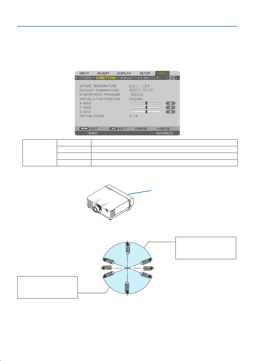
• Whether the option cover needs to be attached in the current installation position can be checked
on the [INFO.] screen of the on-screen menu.
OPTION COVER - / - Option cover is not required
A / - Only option cover A needs to be attached
- / B Only option cover B needs to be attached
A / B Both of option covers A and B need to be attached
Installation angles required to attach the option cover A
Option cover A
In the direction of back and forth
20°–150°
Option cover A must be
attached
90°
270°
180° 0°
200°–330°
Option cover A must be
attached
Important Information
26
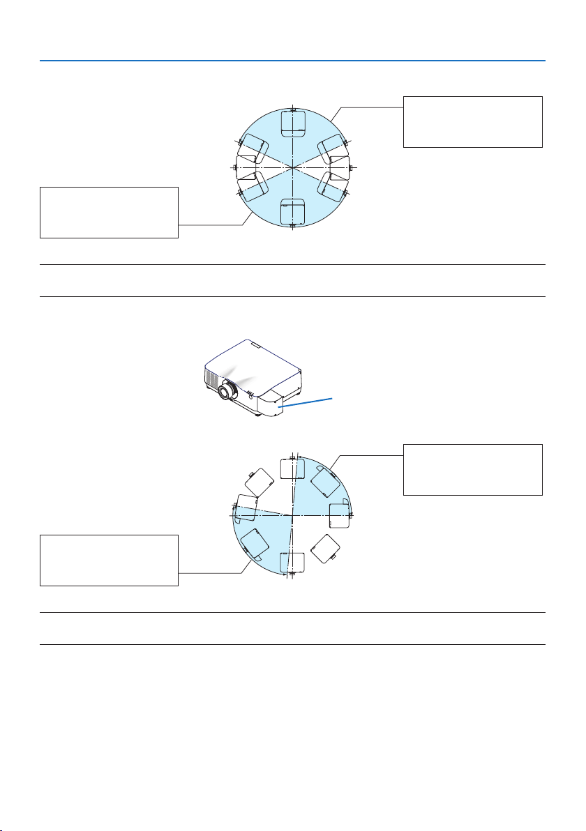
In the direction of left and right
20°–160°
Option cover A must be
attached
90°
270°
180° 0°
200°–340°
Option cover A must be
attached
NOTE:
• The drawings show the image of installation angle as a reference. They are slightly from the actual one.
Installation angles required to attach the option cover B
Option cover B
0°–85°
Option cover B must be
attached
90°
270°
180° 0°
170°–265°
Option cover B must be
attached
NOTE:
• The drawings show the image of installation angle as a reference. They are slightly from the actual one.
Important Information
27
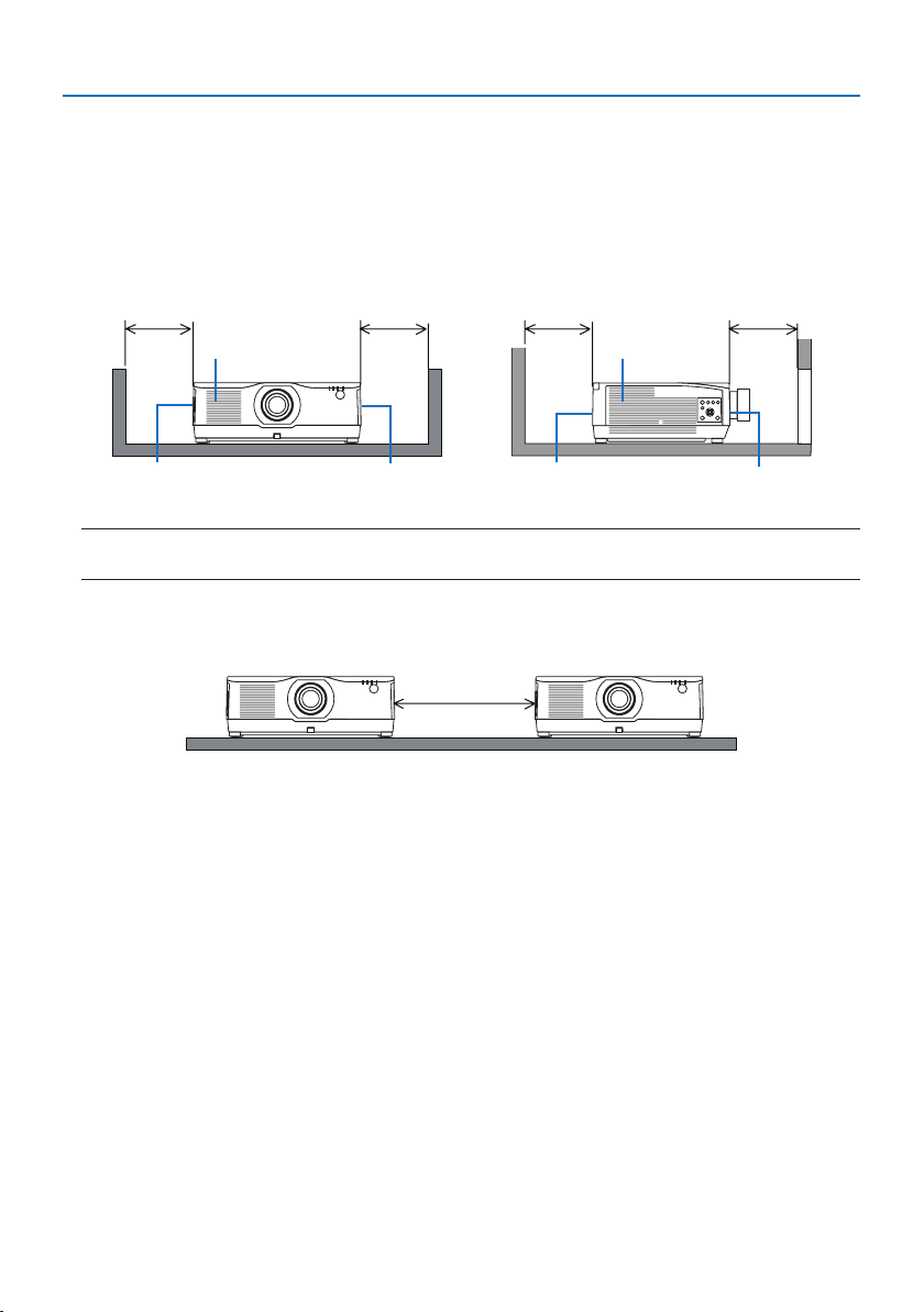
Clearance for Installing the Projector
• When installing the projector, keep sufficient space around it, as described below. If not, the hot
exhaust emitted from the projector may be taken back in.
Also, make sure no wind from an air-conditioner hits the projector.
The projector’s heat control system may detect an abnormality (temperature error) and automati-
cally shut off the power.
Exhaust vent
Intake vent Exhaust vent
Intake ventExhaust vent Intake vent
30 cm/12" or greater 20 cm/8" or greater20 cm/8" or greater 30 cm/12" or greater
NOTE:
• In the above figure, it is assumed that there is sufficient space above the projector.
• When using multiple projectors together for multi-screen projection, provide sufficient space
around the projectors for air intake and exhaust. When the intake and exhaust vents are obstructed,
the temperature inside the projector will rise and this may result in a malfunction.
Precautions for Ceiling Installation
Do not install the projector in the following places. Attached substances such as oil, chemicals and
moisture may cause deformation or cracks of the cabinet, corrosion of the metal parts, or malfunction.
• Outdoors and places with humid or dust
• Places exposed to oil smoke or steam
• Places where corrosive gases are generated
About Copyright of original projected pictures:
Please note that using this projector for the purpose of commercial gain or the attraction of public
attention in a venue such as a coffee shop or hotel and employing compression or expansion of the
screen image with the following functions may raise concern about the infringement of copyrights
which are protected by copyright law.
[ASPECT RATIO], [KEYSTONE], Magnifying feature and other similar features.
[AUTO POWER OFF] Function
The factory default setting for [AUTO POWER OFF] is 15 minutes. If no input signal is received and no
operation is performed on the projector during 15 minutes, the projector is automatically powered
off for saving the power consumption. In order to control the projector by an external device, set
the [AUTO POWER OFF] to [OFF].
28
1-1. Lens unit
Nine separate bayonet style lenses can be used with this projector. The descriptions here are for
the NP41ZL lens. Mount other lenses in the same manner.
Important:
• After installing or replacing the lens unit, press the ZOOM/L-CALIB. button on the projector to carry out [LENS CALIBRATION]. By
carrying out [LENS CALIBRATION], the adjustment range of the lens shift is calibrated.
• [LENS CALIBRATION] is not available for the lens unit NP44ML.
WARNING:
(1) Turn off the power and wait for the cooling fan to stop, (2) disconnect the power cord and
wait for the unit to cool before mounting or removing the lens. Failure to do so can result in eye
injury, electric shock, or burn injuries.
Important:
• The projector and lenses are made of precision parts. Do not subject them to shock or excessive forces.
• Remove the separately sold lens when moving the projector. If not, the lens could be subject to shock while the projector is being
moved, damaging the lens and the lens shift mechanism.
• When dismounting the lens from the projector, return the lens position to the home position before turning off the power. Failure
to do so may prevent the lens from being mounted or dismounted because of narrow space between the projector and the lens.
• Never touch the lens surface while the projector is operating.
• Be very careful not to let dirt, grease, etc., on the lens surface and not to scratch the lens surface.
• Perform these operations on a flat surface over a piece of cloth, etc., to prevent the lens from getting scratched.
• When leaving the lens off the projector for long periods of time, mount the dust cap on the projector to prevent dust or dirt from
getting inside.
• After installing the lens unit NP44ML on the projector, be sure to secure it to the projector using the support kit (NP02LK) sold
separately. For more details, see the handling instructions of the support kit.
Mounting
1. Remove the dust cap from the projector.
1. Attachment/detachment of parts sold separately
1. Attachment/detachment of parts sold separately
29
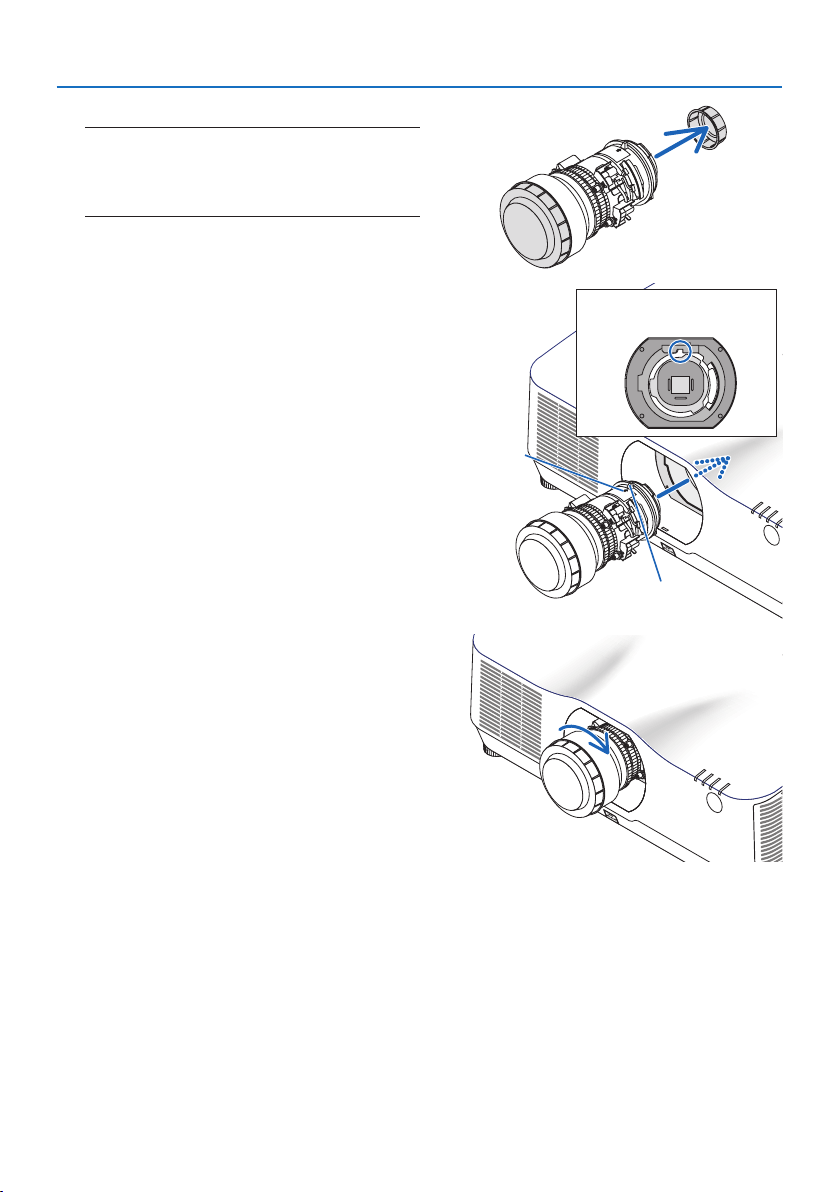
2. Remove the lens cap on the back of the lens.
NOTE:
• Make sure to remove the lens cap at the unit back side. If
the lens unit with the lens cap remaining on is installed
on the projector, it may cause of malfunction.
3. Insert the lens onto the projector facing the
arrow on the lens-label upward.
Insert the lens slowly all the way in.
Guiding notch
Protrusion
Arrow
4. Turn the lens clockwise.
Turn until a click is heard.
The lens is now fastened onto the projector.
1. Attachment/detachment of parts sold separately
30
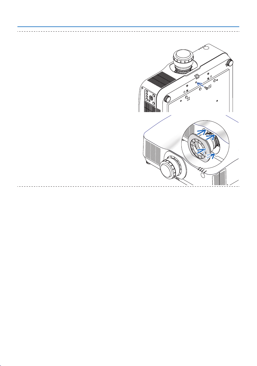
TIP:
• Fasten the lens theft prevention screw included with the projec-
tor to the bottom of the projector so that the lens cannot be
removed easily.
• Attach the enclosed lens mask if you want to hide the gap
between the projector and lens.
• The lens mask cannot be attached when using the NP44ML lens
unit.
• The lens mask may cover the zoom lever or zoom ring and hinder
zoom adjustments when using NP12ZL/NP13ZL/NP14ZL/NP15ZL
lens units.
1. Attachment/detachment of parts sold separately
31
Removing
Preparations:
1. Turn on the projector and display an image.
2. Press and hold the SHIFT/HOME POSITION button over 2 seconds. The lens position will be
moved to the home position.
3. Turn off the main power switch, and then unplug the power cord.
4. Wait until the projector cabinet is cool enough to handle.
5. If the lens theft prevention screw has been set on, remove it. In addition, remove the lens mask
if one is fitted.
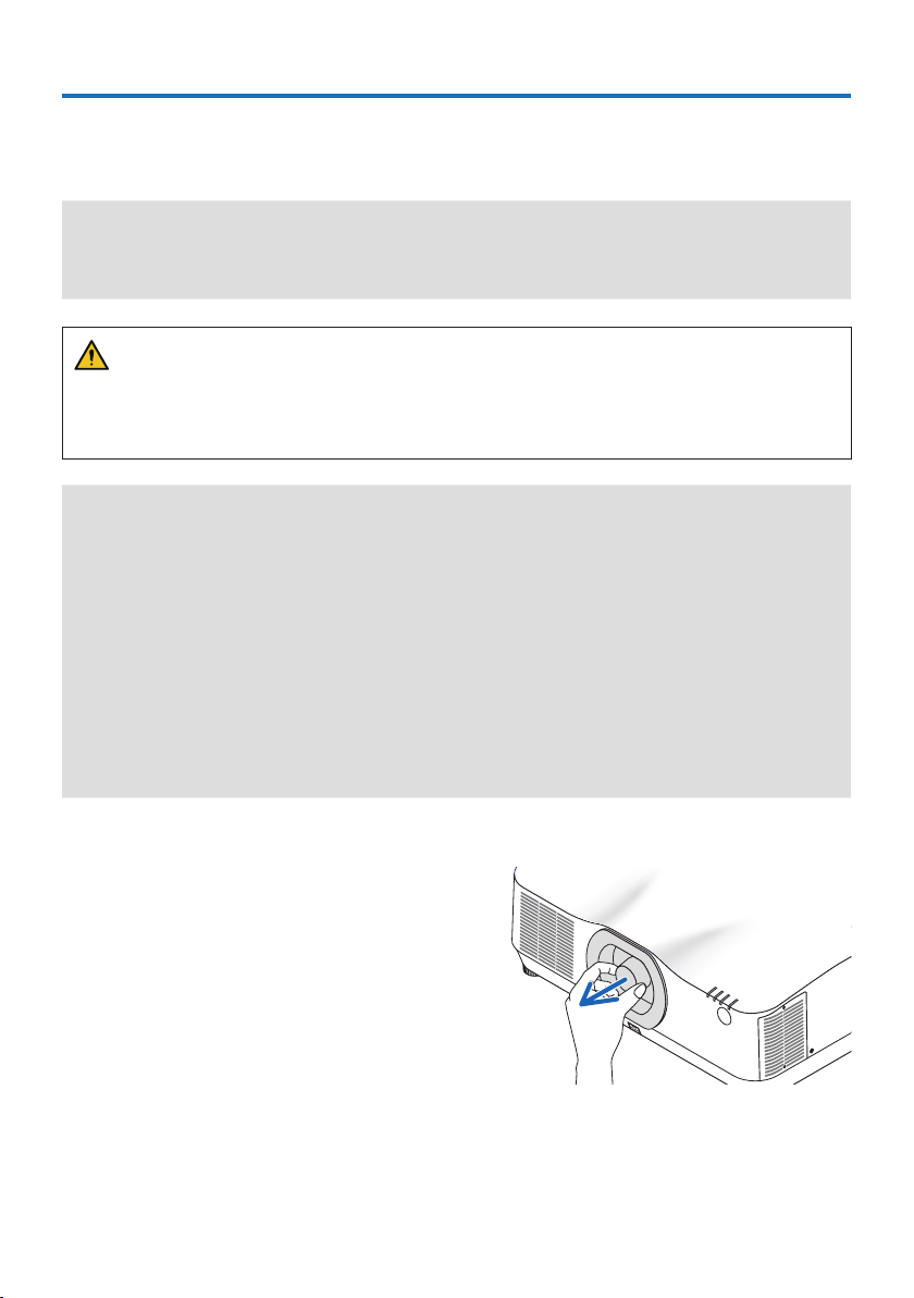
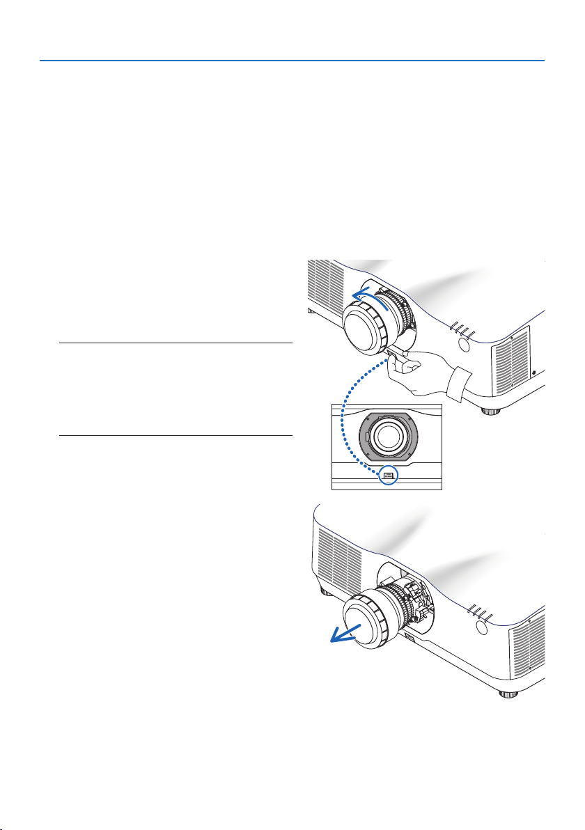
1. While pressing the lens release button at
the bottom of lens mounting section on the
projector’s front panel fully in, turn the lens
counterclockwise.
The lens comes off.
NOTE:
• Check the following areas if the lens unit cannot be
removed even when the lens release button is pressed.
1. The lens release button may be locked sometimes. In
that case, turn the lens fully to the right. The lens release
button lock will be released.
2. Slowly pull the lens off the projector.
• After removing the lens, mount the lens
caps (front and back) included with the
lens before storing the lens.
• If no lens is going to be mounted on the
projector, mount the dust cap included
with the projector.
1. Attachment/detachment of parts sold separately
32
1-2. Option cover
Model name of option cover
NP13CV-W for PA1004UL-W/PA804UL-W
NP13CV-B for PA1004UL-B/PA804UL-B
The option covers A and B are packaged with the option cover NP13CV-W and NP13CV-B.
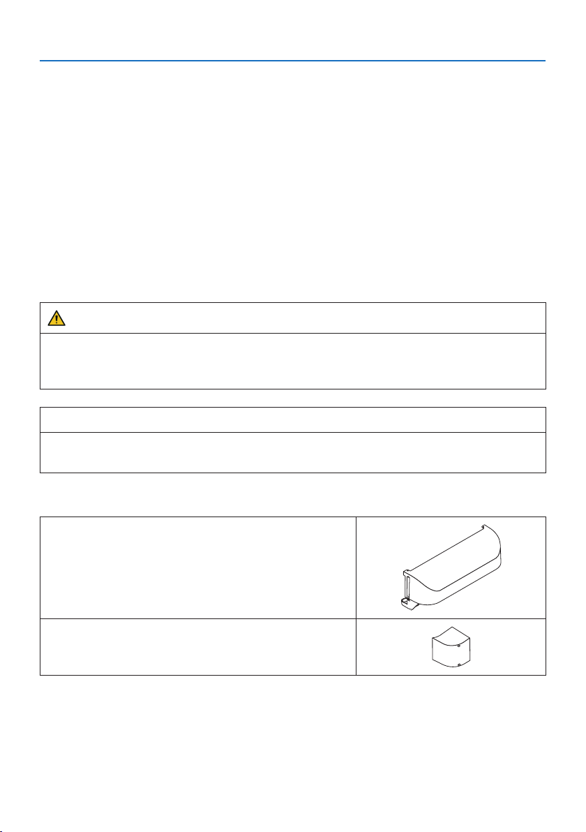
For the following cases, attach the separately sold option cover to the projector.
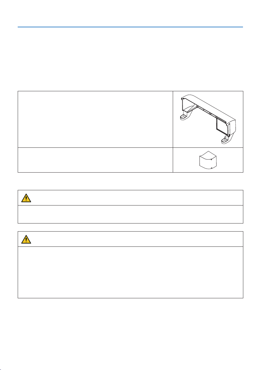
Option cover A
• To make the appearance clean by covering the connected
cables
• To install the projector with its rear upward or downward
Option cover B
• To install the projector with its exhaust vents upward or down-
ward
For installation angles required to attach the option cover, refer to page 24.
WARNING
• When installing the projector at an angle, be sure to attach the option cover for safety.
• Be sure to attach the option cover to the projector when the projector's power is turned on.
CAUTION
About option cover
• After attaching the option cover to the projector, be sure to tighten the screws. If you fail to
do so, the option cover may come off and cause injury, or the option cover may fall and cause
damage.
• Do not bundle the power cord and place it under the option cover. Doing so could lead to fire.
• Do not move the projector by holding the option cover or do not use excessive force to the
option cover. Doing so can cause damage to the option cover, resulting in injury.
Preparations:
• Connect the cables to the projector (the connection cords are omitted from the diagrams).
At this moment, do not connect the power cord.
• Prepare a Phillips screwdriver.
• Place the projector on a soft cloth so as not to scratch the cabinet surface.
1. Attachment/detachment of parts sold separately
33
• Option cover A
Mounting
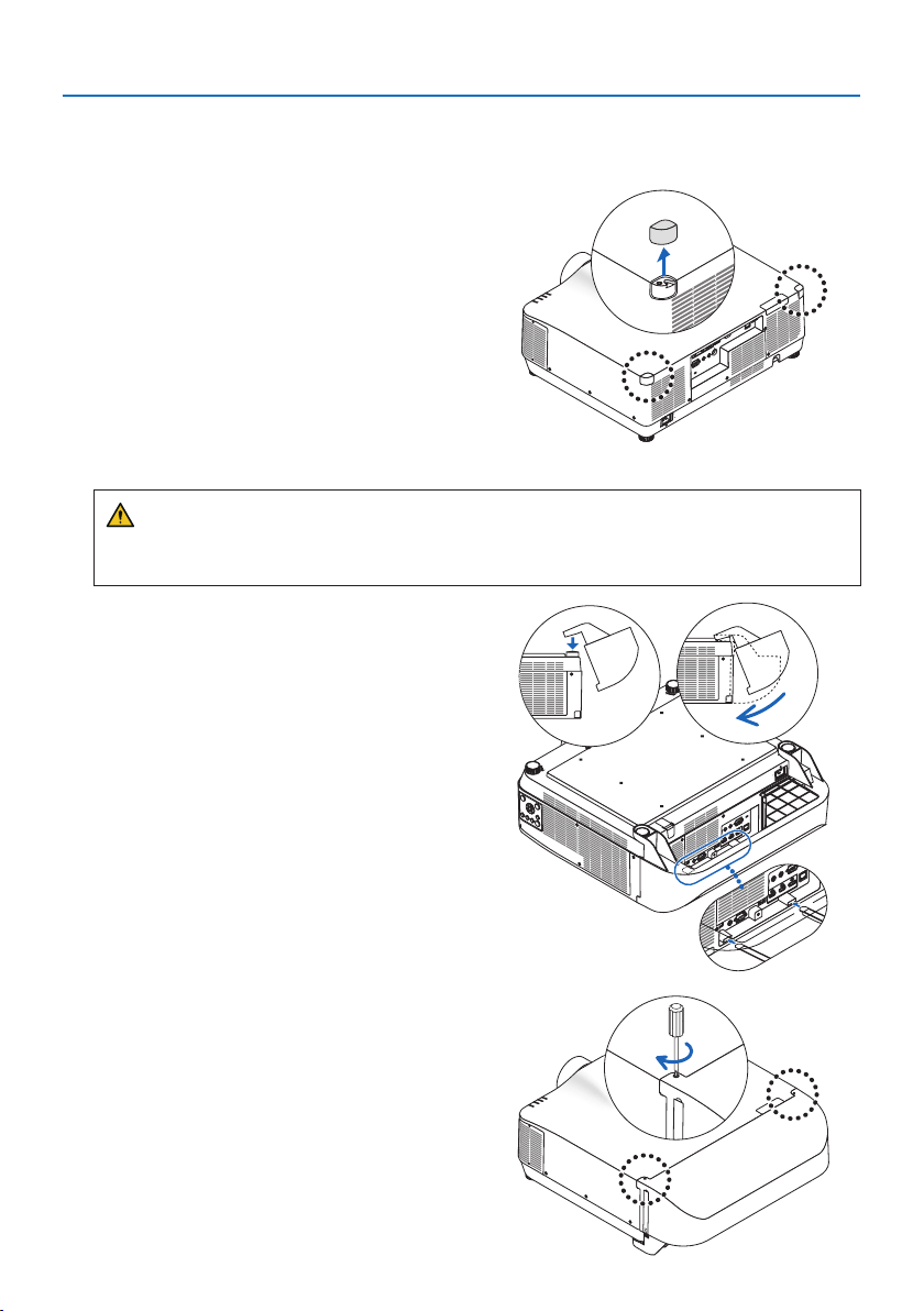
1. Remove the two corner caps from the pro-
jector.
• Keep the removed corner caps for future
use.
2. Turn over the projector.
CAUTION
• For moving the projector, make sure you have at least two people. Attempting to move
the projector alone could result in back pain or other injuries.
3. Attach the option cover A to the projector.
① Shorten the projector tilt foot to the mini-
mum height.
②
Hang the two hooks of the option cover A
on the projector tilt foot.
③
Align the two screw fixing parts of the op-
tion cover A with the place of the corner
caps that were removed at step 1.
At this time, the two hooks in the option
cover will enter the grooves in the projec-
tor.
• If the hooks do not enter easily, check the
positions of the grooves. Do not press the
hooks in by force.
• Be careful not to let the cables get pinched
by the option cover A.
4. Turn the two option cover A screws clock-
wise.
• Tighten the screws securely.
1. Attachment/detachment of parts sold separately
34
Removing
1. Turn the two option cover A screws counterclockwise until it turns loosely.
• The screws are not removable.
2. Remove the option cover A.
Hold up the option cover A to release its two hooks from projector tilt foot.
3. Attach the two corner caps to the projector.
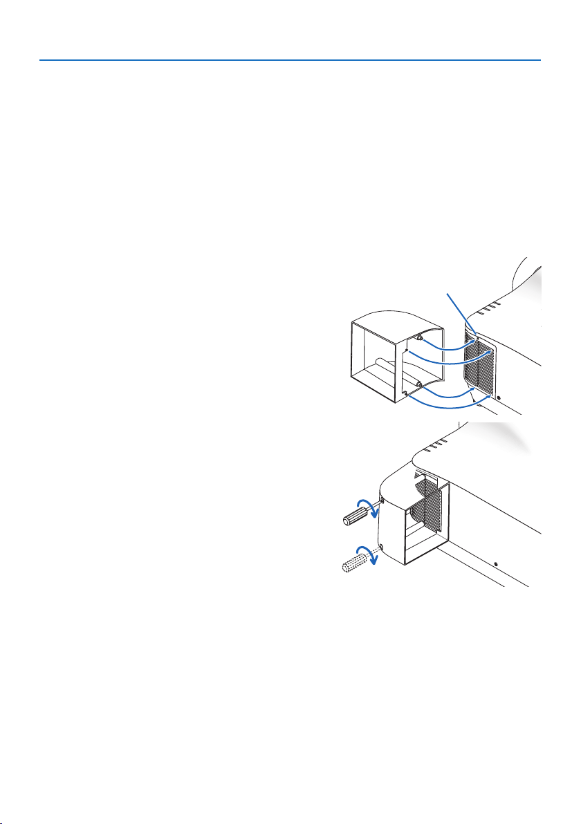
• Option cover B
Mounting
1. Press the two protrusions on option cover B
against the slits in the projector’s exhaust
vent.
• Line up the upper protrusion with the slit
at the very top, the lower protrusion with
the slit at the very bottom.
Screw hole
2. Supporting option cover B by hand, turn
the two screws clockwise to tighten them.
• Tighten the screws securely.
Removing
1. Supporting option cover B by hand, turn the two screws counterclockwise to loosen them
until they turn freely.
• The screws are not removable.
2. Remove the option cover B.

35
2-1. For ceiling installation
• Never try to install the projector yourself in such cases. The projector could drop and cause
injury.
• When installing suspended from the ceiling, use a power outlet that is within reach so the power
cord can be easily plugged and unplugged.
• Do not install the projector in the following places. Attached substances such as oil, chemicals
and moisture may cause deformation or cracks of the cabinet, corrosion of the metal parts, or
malfunction.
- Outdoors and places with humid or dust
- Places exposed to oil smoke or steam
- Places where corrosive gases are generated
• Make sure if the projector is fixed on the surface that has enough durability to stand the whole
projector weight (the projector weight, the lens unit weight, and the ceiling mount weight in
total) for a long time.
• Use fall prevention wire ropes to prevent the projector from falling.
- Use commercially available metal fittings to connect a sturdy part of the building or structure
to the projector with the fall prevention wire ropes.
- Use commercially available metal fittings and fall prevention wire ropes that have sufficient
strength enough to withstand the combined weight of the projector, lens, and ceiling mount.
- When installing the fall prevention wire ropes, do not apply any load on the projector. Tie
your wire rope so that it is slightly slack.
2. Special installation precautions
2. Special installation precautions
36
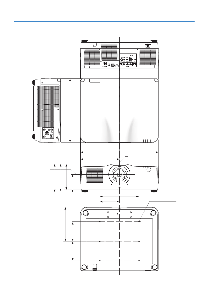
(NaN)
216 (8.5)
262 (10.3)
150 (5.9)
150 (5.9)
134 (5.3)
599 (23.6)
300 (11.8)
150 (5.9)
6-M4
299.5 (11.8)
490 (19.3)
197 (7.8)
208 (8.2)
Cabinet Dimensions
Unit: mm (inch)
Lens center
Lens center
2. Special installation precautions
37
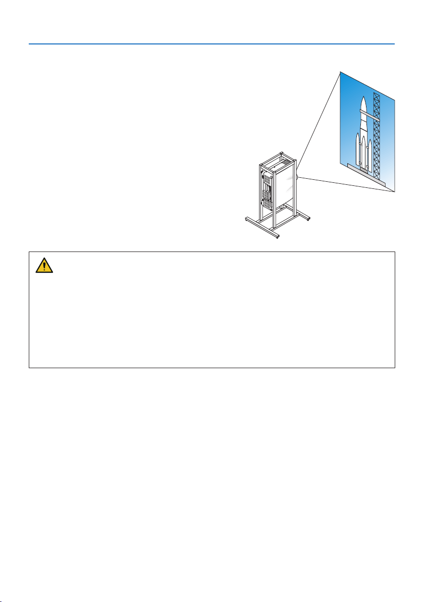
2-2. For portrait projection (vertical orientation)
Portrait screens from a computer can be projected
by installing the projector in a vertical orientation.
Precautions during installation
• Please do not install the projector in a vertical orientation on top of the floor or table on its
own. If not, the projector may fall over, resulting in injury, damage or malfunction. Also, the
exhaust vent may be obstructed, resulting in the projector getting warm and the possibility
of fire and malfunction occurring.
• A stand for supporting the projector needs to be made for portrait projection and for installing
the projector in universal angle. In this case, the stand must be designed such that the center
of gravity of the projector is located well within the legs of the stand. If not, the projector may
fall over and result in injury, damage and malfunction.

2. Special installation precautions
38
Design and manufacturing conditions for the stand
Please engage an installation service provider for the design and manufacture of the customized
stand to be used for portrait projection. Please ensure that the following are complied with when
designing the stand.
1. Secure sufficient space between the projector and the floor. (→ next page)
2. Use the four screw holes at the back of the projector to secure it to the stand.
Screw hole center dimension: width 300 mm, lengthwise pitch 150 mm
Screw hole dimension on the projector: M4 with a maximum depth of 8 mm.
* Please design the stand such that the rear legs at the back of the projector do not contact
the stand. The front legs can be turned and removed.
3. Horizontal adjustment mechanism (for example, bolts and nuts in four locations)
4. Please design the stand such that it does not topple over easily.
2. Special installation precautions
39
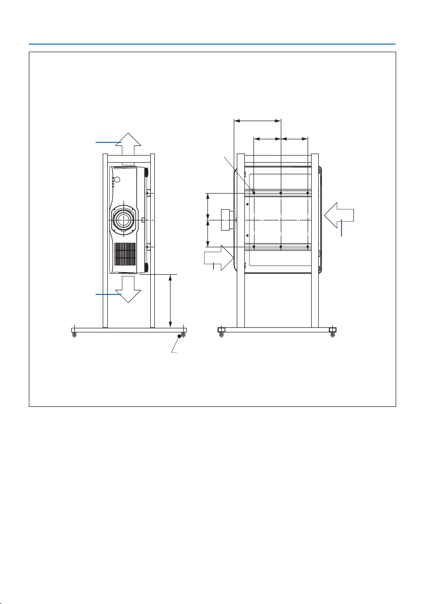
Reference drawings
* The drawing showing the dimensional requirements is not an actual stand design drawing.
(Unit: mm)
[Front View] [Side View]
Screw holes for 6 - M4 use
300 or greater**
262
150 150
Horizontal adjuster
Exhaust
Intake air
Intake air
Exhaust
150 150
** The example shows the right side of the body (side where the control unit is located) facing downwards.
To make the left side of the body (side where the label is pasted) face downwards, leave a space of 200
mm or more.
2. Special installation precautions
40
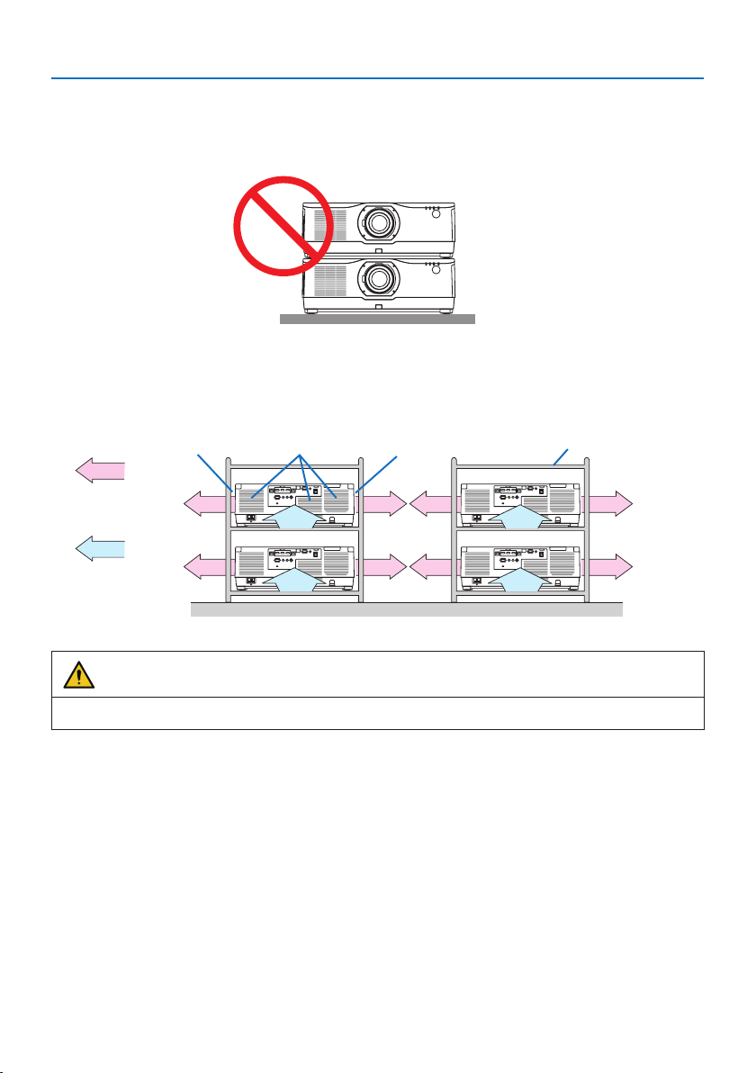
2-3. For multi-Screen projection
• The projector does not support stack installation. Do not stack projectors directly on top of each
other. Failure to do so may cause damage or failure.
• When using multiple projectors together for multi-screen projection, provide sufficient space
around the projectors for air intake and exhaust. When the intake and exhaust vents are obstructed,
the temperature inside the projector will rise and this may result in a malfunction.
Exhaust ventExhaust vent CabinetIntake vent
Air exhaust
Air intake
Back Back
WARNING
Please use a sturdy cabinet that can withstand the weight of the projector for the installation.

In Europe
Sharp NEC Display Solutions Europe GmbH
Address:
Landshuter Allee 12-14
D-80637 Munich, Germany
Telephone: +49 89 99699 0
Email: [email protected]
In North and South America
Sharp NEC Display Solutions of America, Inc.
Address:
3250 Lacey Rd, Ste 500
Downers Grove, IL 60515 U.S.A.
Telephone: +1 800-632-4662
Email: techsupport@sharpnec-displays.com
In Oceania
Australia, DrGroup Global
Address:
Unit 3, 277-281 Sir Donald Bradman Drive,
DOWANDILLA SPA 5033
CUSTOMER CALL CENTRE:
Telephone: 1300 632 435
Email: [email protected]om.au
New Zealand, DrGroup ZN
Address:
28 Walls Road, Penrose,
Auckland, New Zealand
CUSTOMER CALL CENTRE:
Telephone: 0508 855 911
Email: [email protected]o.nz
In Asia
Sharp NEC Display Solutions, Ltd.
Address:
686-1, Nishioi, Oi-Machi, Ashigarakami-Gun,
Kanagawa 258-0117, Japan
Telephone: +81 465 85 2369
NEC (China) Co., Ltd.
Address:
6F, Landmark diplomatic office building D2,
No. 19 East Road, Chaoyang District, Beijing
100600, R.P.C.
Telephone: 010-59342706
NEC Hong Kong Ltd.
Address:
25/F, The Metropolis Tower, 10 Metropolis
Drive, Hunghom, Kowloon, Hong Kong
Telephone: +852 2369 0335
NEC Taiwan Ltd.
Address:
7F, No. 167, SEC. 2, Nan King East Road,
Taipei, Taiwan, R.O.C.
Telephone: +886 2 8500 1710
NEC Asia Pacific Pte. Ltd.
Address:
80 Bendemeer Road,
#05-01/02 Hyflux Innovation Centre,
Singapore 339949
Telephone: +65 6799 6188
NEC Corporation of Malaysia Sdn Bhd
Address:
Suite 20-01, Level 20, The Gardens North
Tower, Mid Valley City, Lingkaran Syed Putra,
59200 Kuala Lumpur
Telephone: +603-2299 6322
© NEC Display Solutions, Ltd. 2020
Ver. 2 4/21