Models:
DUCT09HP230V1AD
DUCT12HP230V1AD
DUCT18HP230V1AD
DUCT24HP230V1AD
SLIM CONCEALED DUCT
OWNER’S MANUAL

Table of Contents
Introduction . . . . . . . . . . . . . . . . . . . . . . . . . . . . . . . . . . . . . . . . . . . 2
Nomenclature . . . . . . . . . . . . . . . . . . . . . . . . . . . . . . . . . . . . . . . . . . 2
Safety Precautions . . . . . . . . . . . . . . . . . . . . . . . . . . . . . . . . . . . . . . 3
System Parts . . . . . . . . . . . . . . . . . . . . . . . . . . . . . . . . . . . . . . . . . . . 4
System Functions . . . . . . . . . . . . . . . . . . . . . . . . . . . . . . . . . . . . 5 - 7
Wired Tether Controller . . . . . . . . . . . . . . . . . . . . . . . . . . . . . . . 8 -16
Wireless Remote Controller . . . . . . . . . . . . . . . . . . . . . . . . . . . 17-22
Care and Cleaning . . . . . . . . . . . . . . . . . . . . . . . . . . . . . . . . . . . . . 23
Troubleshooting . . . . . . . . . . . . . . . . . . . . . . . . . . . . . . . . . . . . . . . 24
Diagnostic Codes . . . . . . . . . . . . . . . . . . . . . . . . . . . . . . . . . . . 25-28
Energy Saving Tips . . . . . . . . . . . . . . . . . . . . . . . . . . . . . . . . . . . . . 29
Warranty . . . . . . . . . . . . . . . . . . . . . . . . . . . . . . . . . . . . . . . . . . . Back
Thank you for choosing a
GreeSlim Concealed Duct
Air Conditioning & Heating System!
You can feel confident in your selection because the same pride in craftsmanship
and engineering knowledge that goes into millions of other Gree installed
products worldwide has gone into your unit.
Please read this owner’s manual carefully before operation and retain it for
future reference.

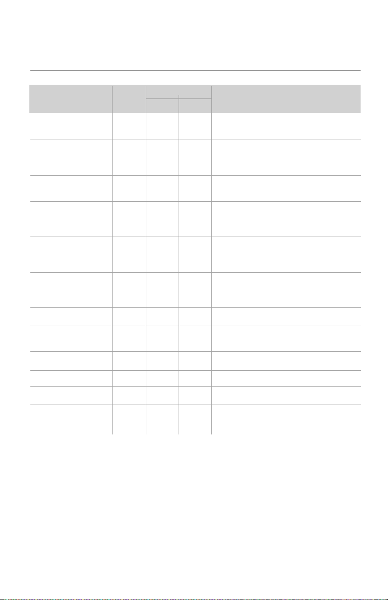
NOMENCLATURE
Superior Design for Superior Performance
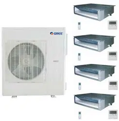
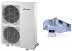
Compact and powerful, this Gree Slim Concealed Duct indoor unit offers the ultimate in
flexibility and discretion. It is designed to be concealed above suspended ceilings or within
open closet spaces to deliver conditioned air via ducting and suitable ceiling or wall grilles.
This arrangement provides immense flexibility, in terms of both the distribution of conditioned
air and the type of grille or diffuser that best complements any room’s styling. Your unit is
easily operated from the wall-mounted wired Tether Controller, or the infrared wireless
Remote Controller.
Like all Gree systems, this unit provides quiet comfort and energy efficient heating and cooling.
For many residential and light commercial applications, it is the ideal solution to balance
comfort, efficiency and ease of use. The Slim Concealed Duct unit works in conjunction with the
Multi21 outdoor compressor section, featuring Gree’s exclusive G-10 Inverter technology. The
Inverter constantly adjusts compressor speed to save energy, reduce outdoor noise and maintain
a steady room temperature, by eliminating the harsh starts and stops of conventional systems.
Thank you for selecting this Gree air conditioner. Before operating your unit,
please read this manual carefully and retain it for further reference.
INTRODUCTION
2
C
o
o
l
i
n
g
Ca
p
a
c
i
t
y
0
9
-
9
,
0
0
0
B
T
U
H
1
2
-
1
2
,
0
0
0
B
T
U
H
1
8
-
1
8
,
0
0
0
B
T
U
H
2
4
-
2
4
,
0
0
0
B
T
U
H
3
0
-
3
0
,
0
0
0
B
T
U
H
3
6
-
3
6
,
0
0
0
B
T
U
H
S
e
r
i
e
s
D
e
s
i
g
n
at
i
o
n
Re
v
i
s
i
o
n
L
ev
el
S
t
yl
e
/
C
o
l
o
r
D
e
s
i
g
n
at
i
o
n
Pr
o
d
u
c
t
T
y
pe
S
-
S
y
s
t
e
m
O
-
O
ut
d
o
o
r
u
n
it
s
H
-
I
n
d
o
o
r
H
i
g
h
W
a
l
l
D
-
I
n
d
o
o
r
D
u
c
t
C
-
I
n
d
o
o
r
C
a
s
s
e
t
t
e
F
-
I
n
d
o
or
F
l
o
o
r/
C
e
i
l
i
n
g
El
e
c
tr
i
c
a
l
R
a
t
i
n
g
2
3
0
V
-
2
0
8
/
2
3
0
V
6
0
H
z
1
P
H
M
o
d
e
l
Ty
p
e
AC
-
C
o
o
l
i
n
g
O
n
l
y
HP
-
H
e
a
t
P
u
m
p
H
C
-
H
e
a
t
/
Co
o
l
1
1
5
V
-
1
1
5
V
6
0
H
z
1
P
H
Example:
DUCT24HP230V1
A
D
D
D
UCT
2
4
H
P
23
0
V
1A
M
U
L
T
I
-
M
u
l
t
i
p
l
e
P
o
r
t
O
u
t
d
o
o
r
U
n
i
t
D
U
C
T
-
S
l
i
m
D
u
c
t
C
A
S
-
C
e
i
l
i
n
g
C
a
s
s
e
t
t
e
F
L
R
-
F
l
o
o
r
/
C
e
i
l
i
n
g
C
O
N
S
-
F
l
o
o
r
C
o
n
s
o
l
e
• Disconnect electrical power to the indoor and outdoor units before performing any
maintenance or cleaning.
• Do not attempt to repair the
Gree
system yourself. Incorrect repairs may cause electric
shock or fire. Contact a qualified service technician for all service requirements.
• Keep combustible materials away from the unit.
• Do not put hands or any objects into the air inlets or outlets. This may cause personal
injury or damage the unit.
• When cleaning, be careful not to splash water on the unit. Doing this may cause
electric shock or damage to unit.
• In the event of a failure (burning smell, etc.), immediately disconnect all electrical
power to indoor and outdoor units.
SAFETY PRECAUTIONS
Please read the following before operation.
Recognize safety information. This is the safety-alert symbol. When you see this symbol on
the unit and in instructions or manuals, be alert to the potential for personal injury. Understand
these signal words: DANGER, WARNING, and CAUTION. These words are used with the
safety-alert symbol.
DANGER identifies the most serious hazards which will result in severe personal injury or death.
WARNING signifies hazards which could result in personal injury or death.
CAUTION is used to identify unsafe practices which may result in minor personal injury or
product and property damage.
NOTE is used to highlight suggestions which will result in enhanced installation, reliability, or operation.
NOTE: Your actual air conditioning & heating system and related devices may differ from
the images shown in this manual.
This appliance is not intended for use by children without responsible adult supervision.
Proper care should be taken to ensure safety.
Heat pumps, air conditioners & heating equipment should be installed, started up, and
serviced only by qualified installers and service technicians. Air conditioning, heat pumps
and refrigeration systems are hazardous due to high voltage electrical components, high
refrigerant pressures, and moving parts.
WARNING
WARNING
WARNING
CAUTION
3
4
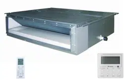
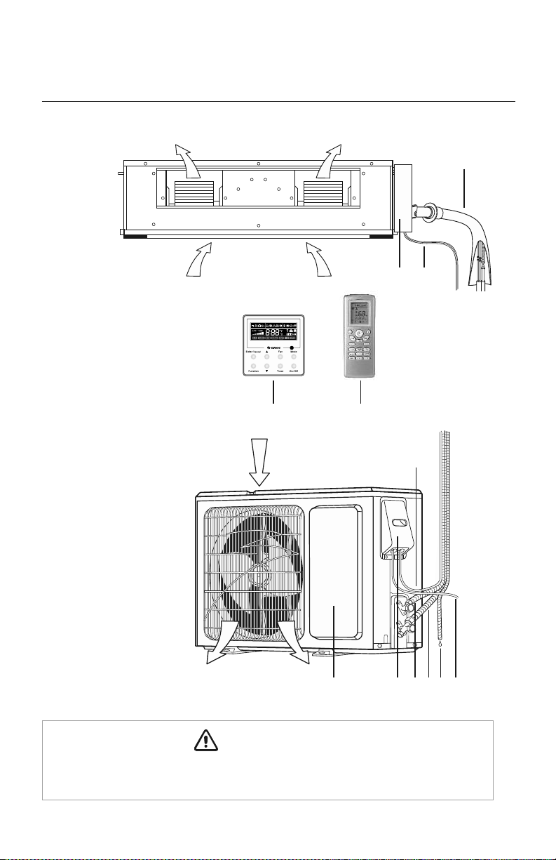
SYSTEM PARTS
Indoor Unit
Part Name
1. Gas & Liquid Pipes
2. Electric Box
3. Interconnection Cable
4. XK-19 Wired Tether Controller
5 Remote Controller
6. Interconnection Cable
7. Front Panel
8. Service Cover
9. Liquid Pipe
10. Gas Pipe
11. Drain Hose
12. Outdoor Power Supply
Outdoor Unit
3
1
Air outlet
Air outlet
Air inlet
Air inlet
2
11
10
98
12
7
The refrigerant pipe, drain pipe, electrical wiring, and duct for this unit should be installed
by a qualified HVAC professional only.
CAUTION
6
45

SYSTEM FUNCTIONS
WHISPER QUIET
Not only are the Gree systems energy efficient but they are quiet too. Slim Duct operates with
sound levels starting as low as 31 dB(A).
MULTI FAN SPEEDS
Whether operating in either Cooling or Heating mode, the indoor fan can be set to your choice
of three different speeds (Low, Medium or High) to achieve maximum comfort.
BUILT IN CONDENSATE LIFT PUMP
The unit features a built-in drain pump that lifts condensate up to 11 inches above the drain
pan to a gravity condensate drain system. In most cases, the internal condensate lift mechanism
will avoid the need for an external condensate pump.
CONDENSATE SENTRY
The unit’s fail-safe mechanism recognizes when there is a high level in the condensate pan
and shuts off the system to prevent overflow.
INTELLIGENT PRE-HEATING
Slim Duct guards against the annoying cool air blown into the room in heating mode. The
system constantly monitors the discharge air temperature. It will delay the indoor fan until
the indoor coil has warmed up to prevent blowing uncomfortable cool air into the room.
CONTROLLERS
The Slim Duct unit comes with a factory supplied Wireless Remote Controller and a Wired
Tether Controller.
WIRELESS REMOTE
The Gree multi-functional infrared hand held wireless controller is sleek, ergonomically
designed, easy to use and has a large backlit LCD display.
TETHER CONTROLLER
The Gree wired Tether Controller mounts to the wall up to 26 feet from the unit.
It provides complete control over your unit’s operation mode, desired temperature,
fan speed, airflow direction and more.
5

SYSTEM FUNCTIONS
INTELLIGENT DEFROST
The Intelligent Defrost function increases room comfort and saves energy by eliminating
unnecessary defrost cycles. In heating mode, the unit will monitor the outdoor coil for frost
buildup. Once frost buildup has been detected, the system will switch into a defrost mode to
remove the frost.
I FEEL MODE
In Cooling Mode, the unit will sense room temperature at the Tether Controller instead of at
the indoor unit. It then adjusts airflow and temperature accordingly for the ultimate in personal
comfort control and energy savings.
POWER FAILURE MODE
Power interruptions are no problem for the
Slim Duct
system. User selections and system parameters
are stored in non-volatile memory. These parameters are retained during a power failure. When
power is returned, the Slim Duct system will automatically return to the last operating mode.
TURBO MODE
Use Turbo Mode for situations where you wish to achieve the desired room temperature in the
shortest possible time. This mode runs the unit at ultra high speeds for quickest results.
CLOCK
The Tether and wireless controllers have a built-in clock feature. The remote will display the time
of day in a 24-hour format.
TIMER MODE
The unit can be programmed to turn ON or OFF after a specific amount of time. The time period
is adjustable between one half and 24 hours.
MODE BUTTON
The unit can be set to five different operating modes: HEAT, COOL, DRY, FAN ONLY and AUTO.
NOTE: AUTO MODE has fixed setpoints of 68 °F heating and 78 °F cooling, which are
not adjustable. The system will automatically select heating or cooling to maintain room
temperature within this band.
FAHRENHEIT °F / CELSIUS °C
The remote controller can be set to display in either °F or °C.
6

SYSTEM FUNCTIONS
SLEEP MODE
The unit will automatically adjust room temperature during your sleep time. This slight change
in temperature will not affect your comfort level due to the natural effects that sleeping has
on the body, but it will save on energy consumption and will lower electric bills.
X-FAN MODE
When operating in humid areas, the X-fan or Dry Coil function allows the indoor fan to run
for a pre-determined amount of time after the unit is turned off (cooling or dry modes) to
ensure that additional moisture is removed from coil.
SELF-DIAGNOSIS
With an on-board computer using real-time diagnostics, the Slim Duct system helps to
prolong its own life. The automatic diagnosis feature continuously scans for unacceptable
operating conditions or malfunctions. If such conditions occur, the system takes corrective
action or stops. Error codes are shown on the Tether Control display to facilitate easy
troubleshooting and repair.
PRIVACY LOCK MODE
The Tether and wireless controllers have a Privacy Lock. The Privacy Lock averts unauthorized
access or tampering with system settings.
AGENCY LISTINGS
All systems are listed with AHRI (Air conditioning, Heating, and Refrigeration Institute)
and are ETL certified per UL Standards.
7
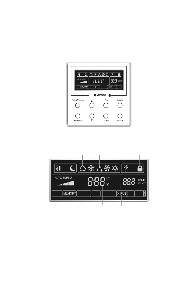
Wired Tether Controller
INTRODUCTION FOR ICONS ON DISPLAY SCREEN
OPERATION OF WIRED TETHER CONTROLLER
1
Part Name
1. Swing Louver
2. Sleep Function
3. Auto Mode
4. Cool Mode
5. Dry Mode
6. Fan Mode
7. Heat Mode
8.
Outdoor Unit
Defrost Function
9. Keypad Lock Function
10. Turbo Function State
11. Memory Function
(power failure
recovery mode)
12.
Ambient/setting
Temperature Value
13. X-Fan Function
14. Timer Function Value
1110 12 13 14
2 3 4 5 6 7 8 9
8
9
OPERATION OF WIRED TETHER CONTROLLER
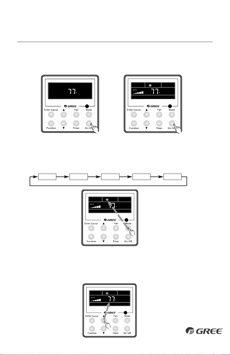
ON/OFF BUTTON
Press On/Off to turn On the unit. Press again to turn it Off.
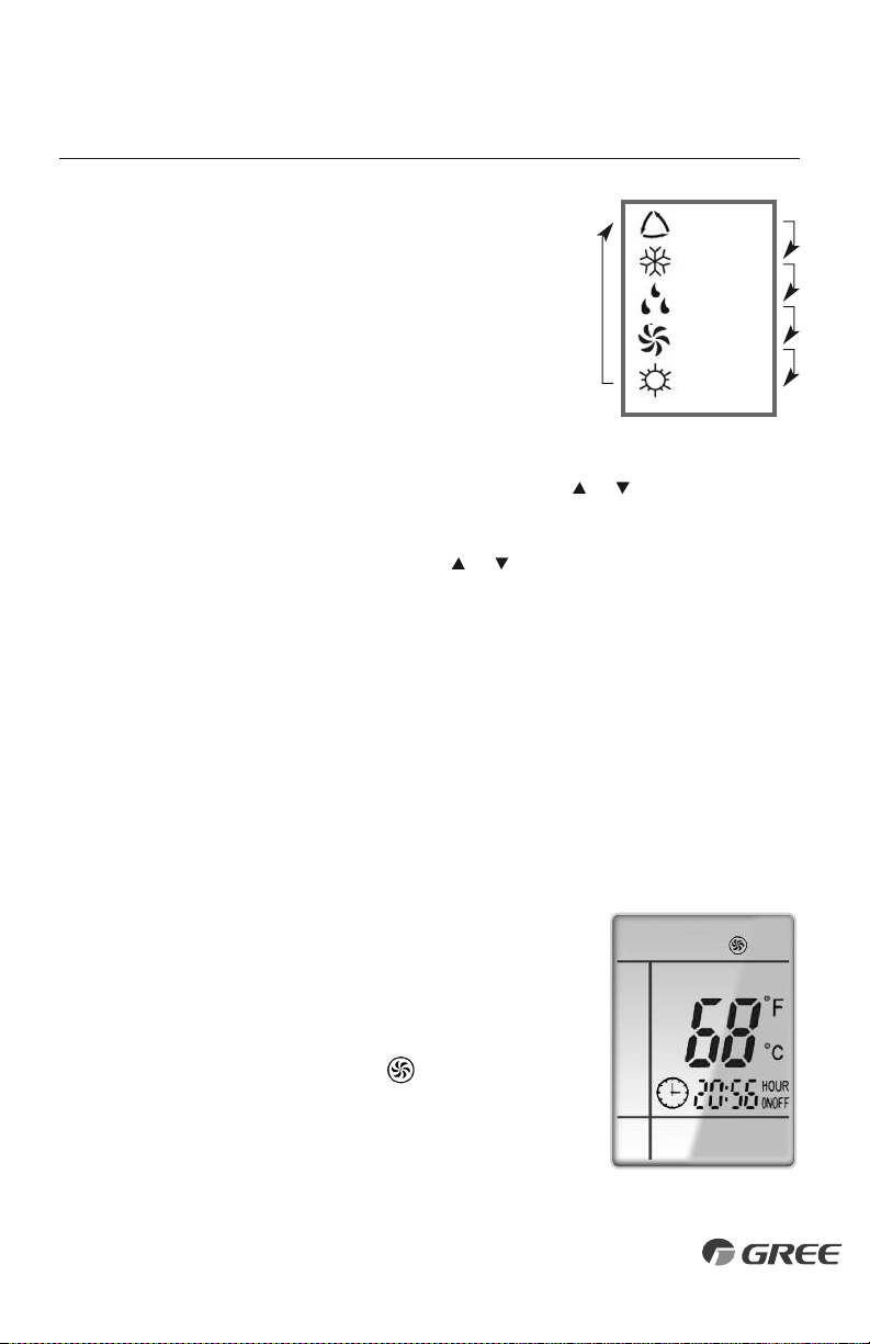
MODE SETTING
When the unit is ON, press Mode button to select an operating mode. It will change
sequentially as shown below: Auto–Cool–Dry–Fan–Heat
“Off” State “O n” State
Auto Cool Dry Fan Heat
F
F
F
TEMPERATURE SETTING
Press ▲ or ▼ to increase/decrease the setpoint temperature as shown below. In Cool, Dry,
Fan or Heat mode, the setpoint temperature range is 61°F - 86 °F. In Auto mode, the setpoint
temperature is not adjustable.
F
OPERATION OF WIRED TETHER CONTROLLER
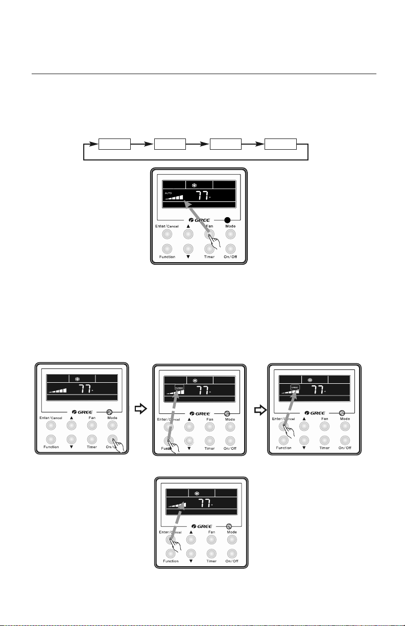
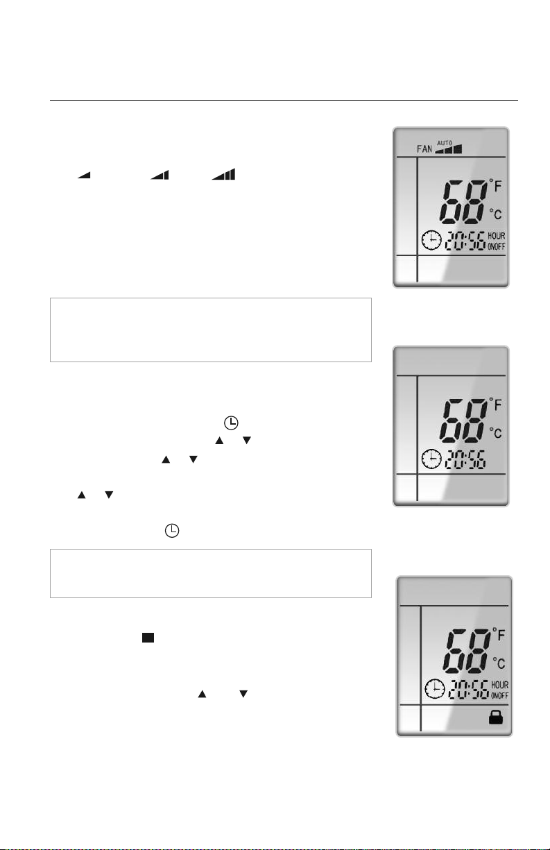
FAN SETTING
When the unit is ON, press Fan button to select the fan speed of the indoor unit. It will change
sequentially as shown below.
10
Auto Low Medium High
F
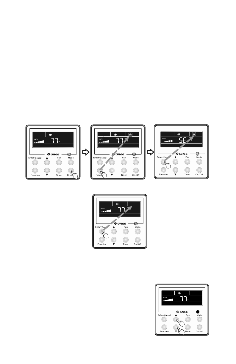
TURBO MODE
Turbo mode will force the unit up to maximum capacity to heat or cool the room in the shortest
amount of time. Turbo Mode can only be used on Heat or Cool modes.
Turbo Setting
Press Function button until the Turbo icon is displayed. Then press Enter/Cancel to confirm. To
cancel, press the Function button to re-enter the Turbo setting status, then press Enter/Cancel.
F
F
F
Turn On the unit and select Heat or Cool mode. Press Enter/Cancel to start Turbo mode.
To cancel, press Function button to re-enter
the Turbo settings, then press Enter/Cancel button.
Press Function until Turbo mode Icon is displayed.
Cancel Turbo Mode
F
11
OPERATION OF WIRED TETHER CONTROLLER
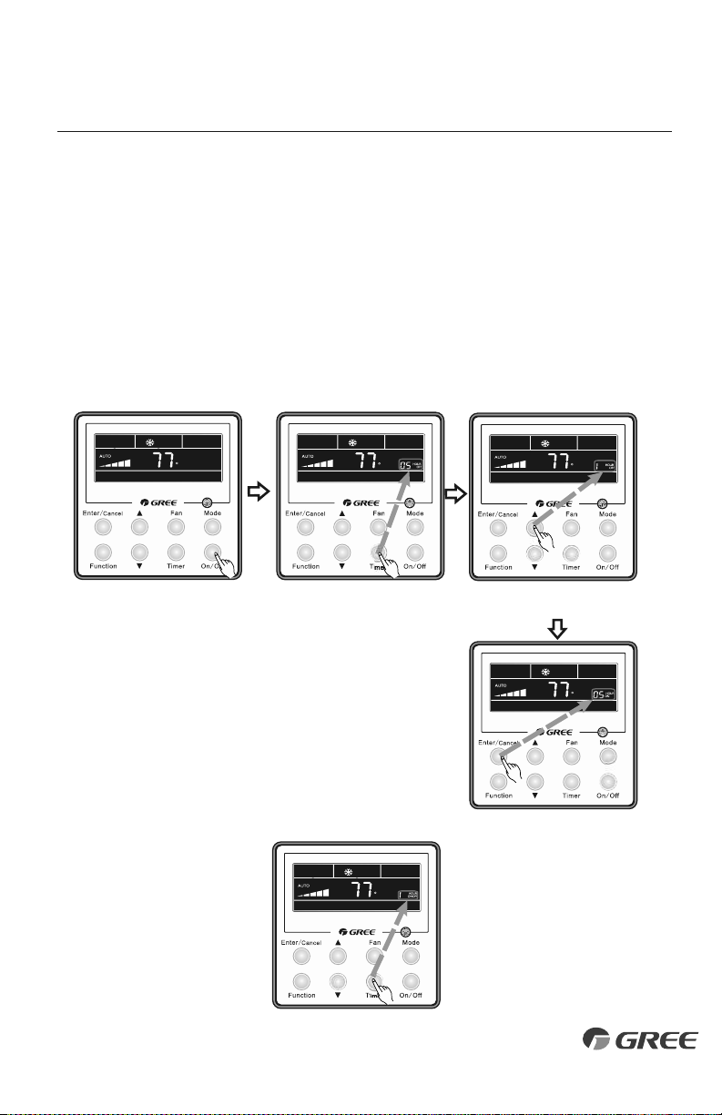
TIMER SETTING
The Slim Duct system has two timer modes. The Timer-On mode will turn the unit ON after
the preset time period. The Timer-Off Mode will turn the unit OFF after the preset time period.
The preset time period can be from 0.5 to 24 hours in 0.5 hour increments.
Timer-On Setting
Turn the unit Off, press the Timer button. The OFF icon will flash and the hours will be displayed
.
Set the time period for the unit to remain OFF before turning ON by pressing the ▲ or ▼
buttons. Press Timer button to confirm and start Timer-On mode.
F
F
F
F
F
Turn Off the unit.
Press Timer button to select Timer On mode.
Press ▲ or▼ to select time period.
Timer modes can be cancelled anytime
by pressing the Timer button.
Cancel Timer
F
Press Enter/Cancel to start timer mode.
12
OPERATION OF WIRED TETHER CONTROLLER
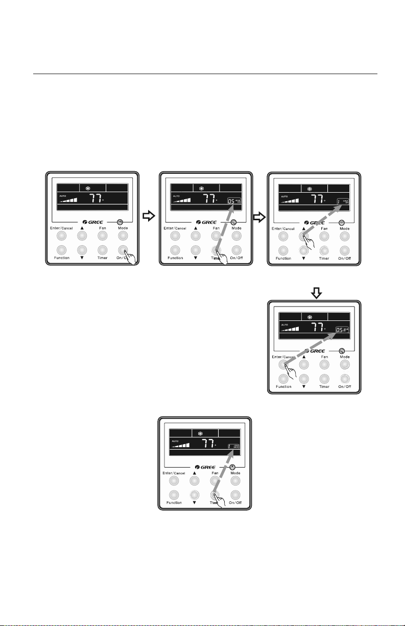
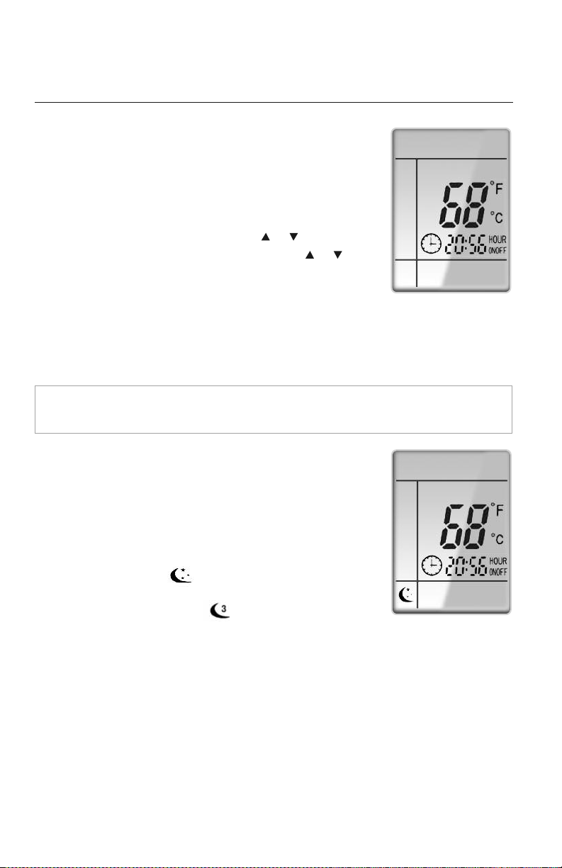
Timer-Off Setting
Turn the unit On, press the Timer button. The ON icon will flash and the hours will be displayed.
Set the time period for the unit to remain ON before turning OFF by pressing the
▲ or ▼
buttons. Press Timer button to confirm and start Timer-Off mode.
F
F
F
F
F
Turn On the unit and select Heat
or Cool mode.
Press Timer button to select Timer Off mode.
Press ▲ or▼ to select time period.
Timer modes can be cancelled anytime
by pressing the Timer button.
Cancel Timer
F
Press Enter/Cancel to start timer mode.
SLEEP MODE
The unit will automatically adjust room temperature during your sleep time. This slight change
in temperature will not affect your comfort level due to the natural effects that sleeping has
on the body, but it will save on energy consumption and will lower your electric bill. Press the
SLEEP button to select Sleep Mode. The SLEEP icon will appear.
In Cool or Dry modes:
The unit will run at current room setpoint for 1 hour. After 1 hour, the setpoint will increase
by 2 °F. After 2 hours, the setpoint will increase by 4 °F and maintain this setpoint until Sleep
Mode is canceled.
In Heat mode:
The unit will run at current room setpoint for 1 hour. After 1 hour, the setpoint will decrease
by 2 °F. After 2 hours, the setpoint will decrease by 4 °F and maintain this setpoint until Sleep
Mode is canceled.
13
OPERATION OF WIRED TETHER CONTROLLER
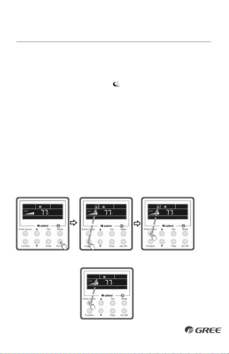
Sleep Setting
Turn the unit On and select a mode (ex. Heat, Cool, or Dry). Press the Function button until
the Sleep icon appears on the display. Press the Enter/Cancel button to start Sleep Mode.
F
FF
F
Turn On the unit and select a mode.
Press Function until the Sleep icon is displayed. Press Enter/Cancel to start Sleep Mode.
Cancel Sleep Mode
Press Function until the Sleep icon appears.
Press the Enter/Cancel button to cancel Sleep Mode.
F
F
F
14
OPERATION OF WIRED TETHER CONTROLLER
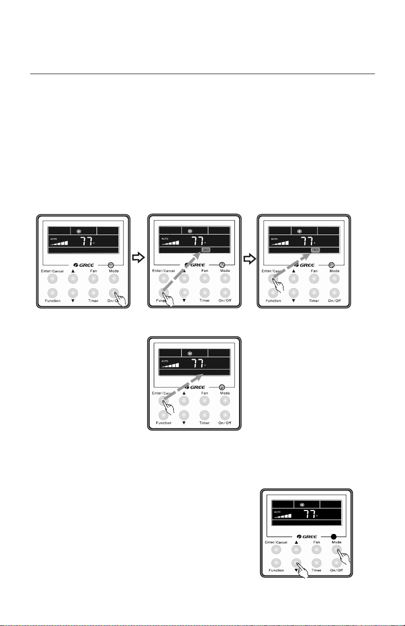
X-FAN MODE
The X-Fan function may only be selected in Cool and Dry modes. After the unit is turned Off,
the X-Fan function will keep the indoor fan running for a predetermined amount of time to dry
the indoor evaporator coil to help avoid mold and mildew growth.
X-Fan Settings
Turn the unit On and select Cool or Dry mode. Press Function button until X-fan icon is
displayed and then press Enter/Cancel to activate this function.
F
Turn On the unit, select Cooling
or Dry mode.
Press Function until the X-fan icon is displayed.
Press Enter/Cancel to start X-fan
mode.
Cancel X-Fan Mode
To cancel, press Function button to re-enter the
X-Fan settings, then press Enter/Cancel button.
CELSIUS OR FAHRENHEIT TEMPERATURE DISPLAY
The wired Tether Controller is set from the factory to display
temperature in Fahrenheit (ºF). If Celsius (ºC) is desired, turn
the unit OFF, press Mode and ▼ buttons at the same time
for 5 seconds to alternate between temperature displays.
F
To change temperature display.
OPERATION OF WIRED TETHER CONTROLLER
I-FEEL MODE
In Cool Mode, the Slim Duct unit will sense room temperature at the wired Tether Controller
instead of at the return air section of the indoor unit.
I-Feel Settings
Press the Function button until the I-Feel icon is displayed, then press Enter/Cancel to
activate the function.
15
F
Turn Unit On.
Press Function until the I-Feel icon is displayed. Press Enter/Cancel to start I-Feel
mode.
To cancel, press Function button to re-enter the
I-Feel settings, then press Enter/Cancel button.
Cancel I-Feel Mode
PRIVACY LOCK
The Privacy Lock prevents unauthorized access to the unit
controls and prevents tampering with system settings. To
lock the wired Tether Controller, press ▲ and ▼ buttons
simultaneously for 5 seconds and the Lock Icon will be displayed.
Repeat the process to unlock the Tether Controller and
cancel Privacy Lock.
To activate Privacy Lock.
POWER FAILURE MODES
The unit has two selectable system power up modes:
IMPORTANT: This mode arrives set at “factory default,” but should not be left there. It must be
reset to “Power Failure Recovery,” especially for use in commercial IT/server/computer rooms.
Power Failure Recovery
After the initial power up, the unit will store user selections and system parameters in
non-volatile memory. These parameters are retained during a power failure. When power is
returned, the system will automatically return to the last operating mode.
Power Failure Standby
The system will power up in standby or off mode. This is the factory default setting.
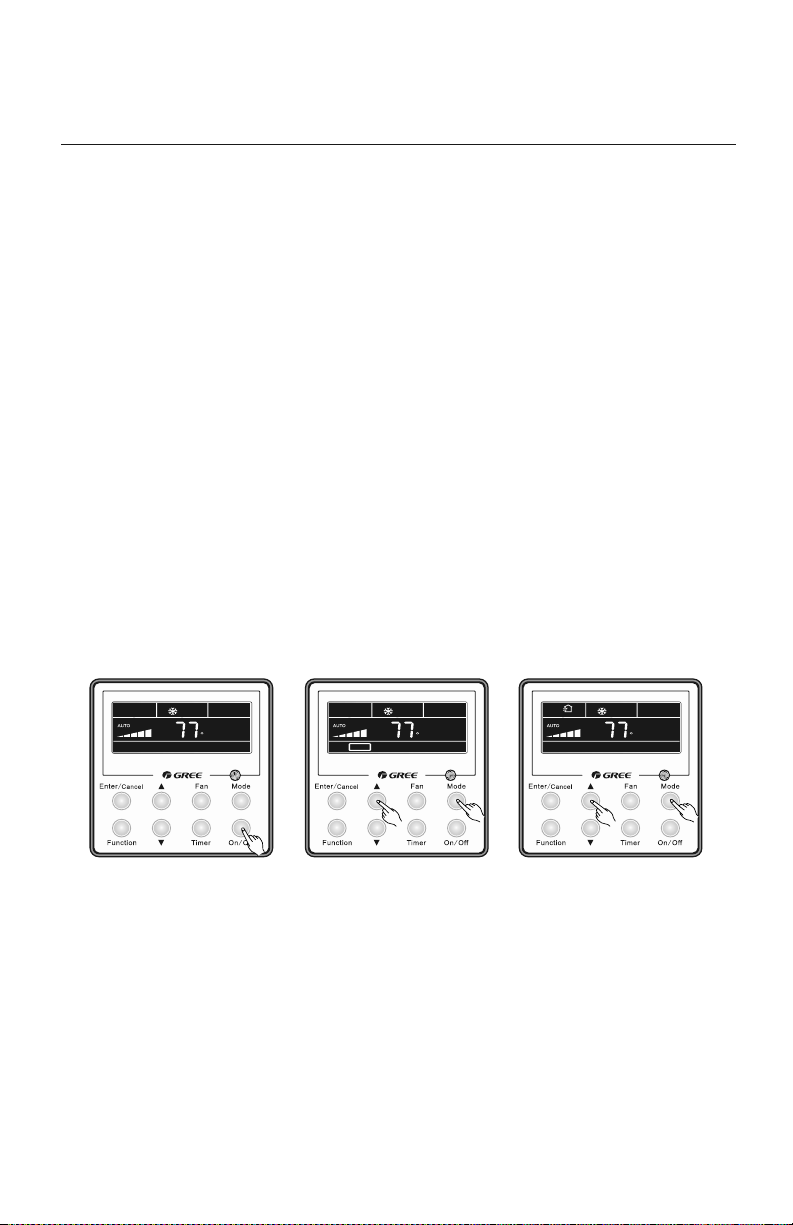
POWER FAILURE MODE SETTINGS
To set Power Failure Recovery Mode, turn the unit OFF and press the Mode and
▲
buttons
simultaneously for 5 seconds until the MEMORY Icon is displayed.
Repeat the process to select Standby mode. In Standby mode the Memory icon is not displayed.
F F F
MEMORY
Turn Unit Off.
Press Mode and ▲ buttons 5 sec
until MEMORY icon is displayed.
Repeat to change Modes.
OPERATION OF WIRED TETHER CONTROLLER
16
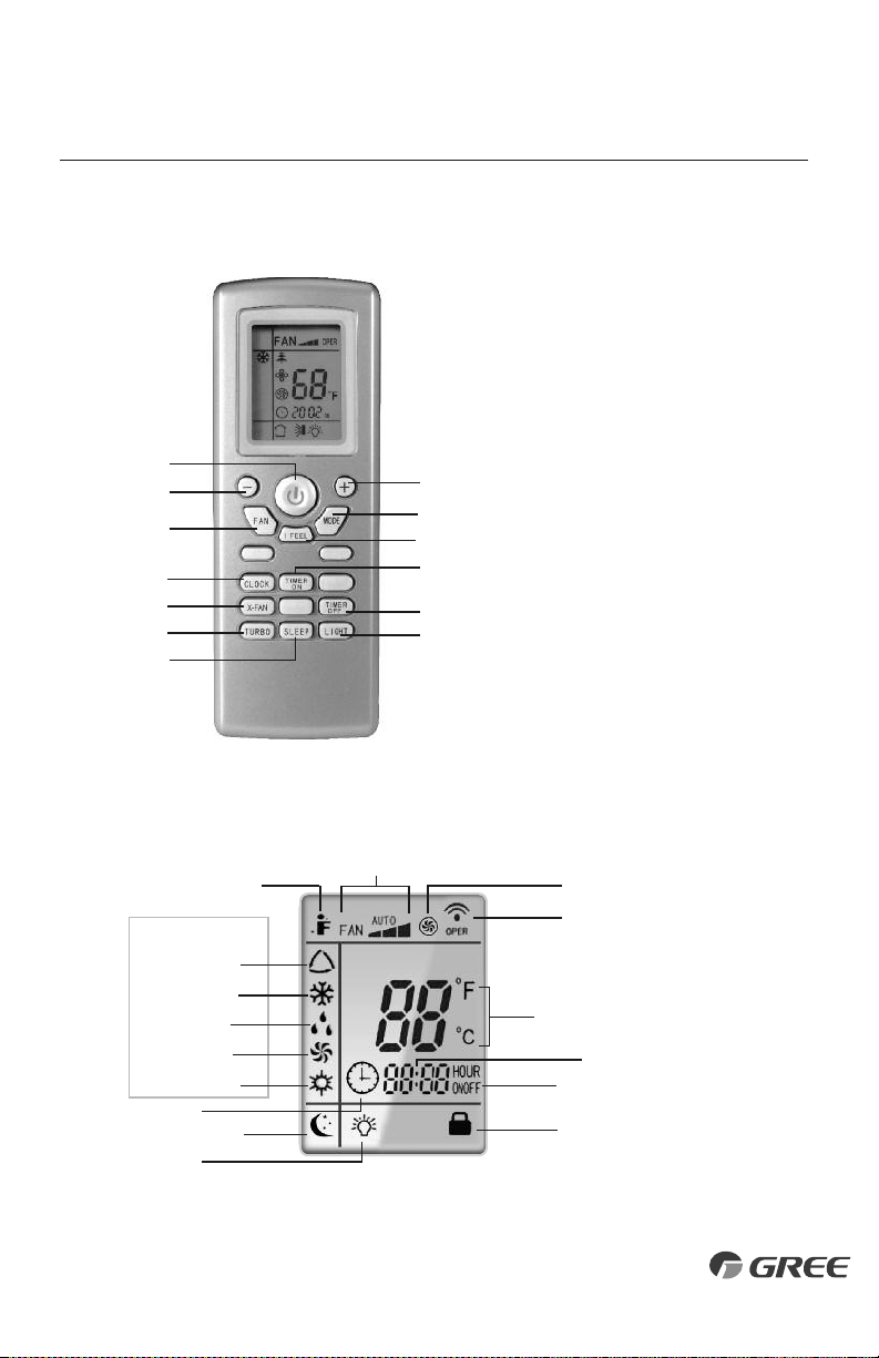
Remote Controller
INTRODUCTION FOR ICONS ON DISPLAY SCREEN
OPERATION OF WIRELESS REMOTE CONTROLLER
Part Name
1. ON/OFF Button
2. Down Button
3. Up Button
4. Fan Button
5. Mode Button
6. I Feel Button
7. Clock Button
8. Timer On Button
9. X-Fan Button
10. Timer Off Button
11. Turbo Button
12. Sleep Button
13. Light Button
1
2
4
7
9
11
3
5
6
8
10
13
12
Auto Mode
Cool Mode
Dry Mode
Fan Mode
Heat Mode
Clock
Sleep Mode
I Feel Function
Light
Send Signal
Turbo Mode
Set Fan Speed
Operation Mode
Set Temperature
Set Time
Timer On/Off
Privacy Lock
17
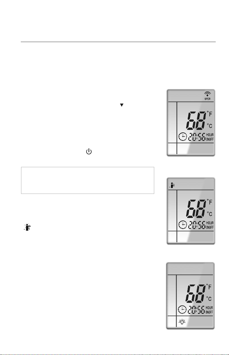
I Feel Mode
I FEEL MODE
In Cool Mode, press this button to use the I FEEL function, and the
( ) icon will be displayed. The unit will sense room temperature
at the remote controller instead of at the indoor unit. It then adjusts
airflow and temperature accordingly for the ultimate in personal
comfort control and energy savings. Press the button again to exit
this function. For best performance, keep remote controller away
from heat or cold temperature sources while using this function.
OPERATION OF WIRELESS REMOTE CONTROLLER
18
REMOTE CONTROLLER OPERATIONS
The wireless remote controller is sleek, versatile and allows you to change room temperatures
and functions on your Slim Duct system from the palm of your hand. The large LCD display
and buttons make it easy-to-understand and easy-to-use.
The remote controller is set from factory to display temperatures
in °F. If °C is desired, turn
the remote controller
OFF
with the
ON/OFF
button and then press “MODE“ and “ ” buttons
on
the remote simultaneously for 5 seconds.
ON/OFF BUTTON
When the system is in OFF mode, the remote controller will
display the time and last room setpoint. When you press the
ON/OFF button, this indicator will be displayed and the
unit will start in the last operating mode and room setpoint.
NOTE: If the ON/OFF button is pressed too soon after a
stop, the compressor will not start for up to 5 min. due to
the inherent protection against frequent compressor cycling.
ON Mode Display
LIGHT BUTTON
Press this button to turn off display light on indoor unit.
Press again to turn it back on.
Light Display
19
MODE BUTTON
Use the “MODE” button to select one of the available modes.
The selected mode will be displayed on the remote controller and
the appropriate light will illuminate on the front display panel.
AUTO – Unit will automatically select heating or cooling
to maintain room temperature between 68 °F and 77 °F.
The remote controller will display the Auto Mode icon with
no setpoint.
COOL – To cool to selected setpoint and remove moisture. Press or to adjust
set temperature. System varies compressor speed to maintain desired temperature.
HEAT – To heat to selected room setpoint. Press or to adjust set temperature.
System varies compressor speed to maintain desired room temperature.
FAN ONLY – To circulate air without heating or cooling. Use Fan Speed button to select
speed from low to high.
DRY – Select DRY MODE to increase moisture removal during warm humid conditions.
In this mode, fan speed cannot be adjusted.
1. If the Room Temperature is above or equal to the set temperature, the system
will be operating with high fan speed for several minutes and then it will switch
to the selected fan speed.
2. If the Room Temperature is below the set temperature, the system will be OFF
and the indoor fan will be at low speed.
: AUTO
: COOL
: DRY
:
FAN ONLY
: HEAT
Icons Displayed
OPERATION OF WIRELESS REMOTE CONTROLLER
TURBO MODE
The desired room setpoint can be achieved faster in TURBO
mode. After selecting the“HEAT”or“COOL” mode button,
push the“TURBO”button. The TURBO icon will be
displayed on the remote controller and the unit will run at an
ultra-high speed. To deactivate the feature, push the“TURBO”
button again. The unit will return to normal operation.
Turbo Mode Display
FAN BUTTON
Press the FAN button to adjust the indoor fan speed:
Low ( ), Medium ( ), High ( ), Turbo and Auto.
NOTE: Turbo function is not available in Dry and Auto Modes.
The Slim Duct unit will select proper fan speed automatically
according to ambient temperature.
OPERATION OF WIRELESS REMOTE CONTROLLER
CLOCK SETTING
Press this button to set clock time.“ ” icon on remote controller
will blink. Within 5 seconds, press or button to set clock time.
With each pressing of or buttons, clock time will increase
or decrease 1 minute. To quickly adjust time setting, press and
hold or button for 2 seconds. Release button when you
have reached the desired time setting. Press “CLOCK” button to
confirm the time, and “ ” icon will stop blinking.
NOTE:
Clock time adopts 24-hour mode. A 12-hour time
format is not available.
• Turbo function is not available in Dry and Auto mode.
• The fan operates at low speed in Dry and Auto modes, and the
speed cannot be adjusted.
• When Auto is selected, the unit will select the proper fan speed
automatically, according to the ambient temperature.
Fan Display
Clock Setting Display
PRIVACY LOCK
The Privacy Lock prevents unauthorized access to the unit controls
and prevents tampering with system settings. The remote controller
can be locked by pushing the""and " " buttons simultaneously
for 5 seconds. The Privacy Lock icon will be displayed on the remote
controller. Repeat the process to unlock the remote controller.
U
Privacy Lock Display
20
OPERATION OF WIRELESS REMOTE CONTROLLER
TIMER SETTING
Timer-ON /Timer-OFF BUTTON
To set when you want the unit to turn On at the end of a selected
time period, use the button labeled “Timer-ON /Timer-OFF”on the
remote controller. Press this button to make the clock icon disappear,
replaced with the word “ON” (blinking). Press or buttons to
adjust timer setting 1 minute
at a time. Press and hold
or
button to set timer more quickly. Press“Timer-ON /Timer-OFF”
button again to confirm setting, and the word “ON” will stop
blinking. To cancel, press“Timer-ON /Timer-OFF” button again.
To set when you want the unit to turn Off at the end of a selected time period, use the
same button. Press this button to make the clock icon disappear, replaced with the word
“OFF” (blinking). Adjust settings the same as with
“Timer-ON /Timer-OFF”
settings.
NOTE: Under Timer On and Off status, you can set“Timer-ON /Timer-OFF”simultaneously.
Before setting timer, be sure to set clock to correct time.
Timer Setting ON/OFF
SLEEP MODE
The Slim Duct system will automatically adjust room temperature
during your sleep time. This slight change in temperature will not
affect your comfort level due to the natural effects that sleeping
has on the body, but it will save on energy consumption and will
lower your electric bill. Press the SLEEP button to select Sleep
mode or Cancel. The SLEEP icon will appear.
TRADITIONAL MODE - SLEEP
In Traditional Mode the unit will slowly relax the room set temperature
by up to 4 °F until Sleep Mode is cancelled.
In Cool or Dry modes:
The unit will run at current room setpoint for 1 hour. After 1 hour, the setpoint will increase by
2 °F (1℃). After 2 hours, the setpoint will increase by 4 °F (2℃) and maintain this setpoint until
Sleep Mode is cancelled.
In Heat mode:
The unit will run at current room setpoint for 1 hour. After 1 hour, the setpoint will decrease by
2 °F (1℃). After 2 hours, the setpoint will decrease by 4 °F (2℃) and maintain this setpoint until
Sleep Mode is cancelled.
Sleep Mode Display
21
22
OPERATION OF WIRELESS REMOTE CONTROLLER
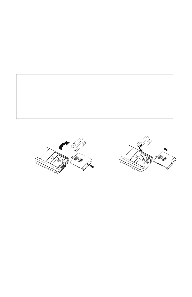
CHANGING BATTERIES AND ADDITIONAL NOTES
To change batteries, slide cover off battery compartment on back of remote controller. Remove
and safely discard old batteries. Insert two new AAA 1.5V dry batteries, using correct polarity.
Reattach back cover.
NOTE:
• If the remote controller will not be used for a long time, remove batteries to prevent
leakage damage.
• Be sure to aim the remote controller at the receiver of the main unit when operating.
• When remote emits a signal, icon will flicker; a tone will be heard when unit receives
that signal.
Remove
old batteries
Install
new batteries
CHANGING BATTERIES
CARE AND CLEANING
23
CAUTION
Take notice of the following items before cleaning your air conditioning unit.
• To avoid electric shock or injury, do not attempt to clean the unit unless it has been
turned off and disconnected from the main power supply.
• Do not wash the unit with water; this may cause an electric shock.
• During cleaning, be sure to use a stable standing platform.
CLEANING THE FILTER
• Never remove the air filter from the unit except for cleaning; otherwise it may cause
dust or dirt to restrict airflow to the unit.
• When the air conditioning unit is used in an environment with heavy dust, the air filter
should be cleaned often (generally once every two weeks).
Perform the following on an annual basis:
• Clean or replace air filter.
• Inspect drain line for potential clogs or leaks.
• Hose off both sides of the coil in the outdoor unit to remove loose debris or dirt buildup.

TROUBLESHOOTING
PROBLEM
S
ystem does not restart.
Indoor unit emits unpleasant
odor when started
You hear a“water flowing”
sound.
A thin fog or vapor coming out
of the discharge register when
system is running.
You hear a slight cracking
sound when the system
stops or starts.
The system will not run.
The unit is not heating or
cooling adequately.
Water leaking from the indoor
unit into the room.
The unit will not deliver air.
CAUSE/SOLUTION
Cause: The system has a built-in 5-minute delay to prevent short and/or rapid cycling of the compressor.
Solution: Wait 5 minutes for the protection delay to expire.
Cause: Typically unpleasant odors are the result of mold or mildew forming on
the coil surfaces or the air filter.
Solution: Wash indoor air filter in warm water with mild cleaner. If odors persist, contact a qualified
service professional to clean the coil surfaces.
Cause: It is normal for the system to make“water flowing”or“gurgling”sounds from refrigerant
pressures equalizing when the compressor starts and stops
Solution: The noises should discontinue as the refrigerant system equalizes after two or three minutes.
Cause: It is normal for the system to emit a slight fog or water vapor when cooling extremely humid warm air.
Solution: The fog or water vapor will disappear as the system cools and dehumidifies the room space.
Cause: It is normal for the system to make “slight cracking” sounds from parts expanding and
contracting during system starts and stops.
Solution: The noises will discontinue as temperature equalizes after 2 or 3 minutes.
Cause: There are a number of situations that will prevent the system from running.
Solution: Check for the following:
• Circuit breaker is “tripped” or “turned off.”
• Power button of controller is not turned on.
• Controller is in sleep mode or timer mode.
• Otherwise, contact a qualified service professional for assistance.
Cause: There are a number of reasons for inadequate cooling or heating.
Solution: Check the following:
• Remove obstructions blocking airflow into the room.
• Clean dirty or blocked air filter that is restricting airflow into the system.
• Seal around door or windows to prevent air infiltration into the room.
• Relocate or remove heat sources from the room.
Cause: While it is normal for the system to generate condensate water in cooling mode,
it is designed to drain this water via a condensate drain system to a safe location.
Solution: If water is leaking into the room, it may indicate one of the following.
• The indoor unit is not level right to left. Level indoor unit.
• The condensate drain pipe is restricted or plugged. All restrictions must be removed to allow
continuous drainage by gravity.
• If problem persists, contact a qualified service professional for assistance.
Cause: There are a number of system functions that will prevent air flow.
Solution: Check for the following:
• In heating mode, the indoor fan may not start for three minutes if the room temperature is very low.
This is to prevent blowing cold air.
• In heat mode, if the outdoor temperature is low and humidity is high, the system may need to
defrost for up to 10 minutes before beginning a heating cycle.
• In dry mode, the indoor fan may stop for up to three minutes during the compressor off delay.
• Otherwise, you should contact a qualified service professional for assistance.
24
25
DIAGNOSTIC CODES
Liquid Valve Coil Temperature
Sensor Malfunction
Gas valve temperature sensor
is open/short circuited
System Configuration
Malfunction
Wrong connection of communication
wire or malfunction of electronic
expansion valve
System High Pressure
Indoor Anti-Freeze Protection
Low Pressure Protection
Compressor High Discharge
Temperature Protection
Overcurrent Protection
Communication Malfunction
Mode conflict (Indoor units
calling for simultaneously
Heating and Cooling)
1) Loose or bad connection between sensor and control board
2) Liquid valve temperature sensor damaged
3) Control board malfunction
Hardware malfunction
1) No jumper cap inserted on the control board
2) Incorrect or damaged jumper cap on control board
3) Indoor and outdoor units are not compatible
Hardware malfunction
1) Over charged with refrigerant
2) Blocked or dirty outdoor coil
3) Extreme outdoor ambient conditions
1) Low return airflow
2) Indoor fan speed is too low
3) Indoor coil is blocked or dirty
1) Low on refrigerant
2) Pressure sensor is damaged
Please refer to the malfunction analysis (discharge
temperature, overload) in service manual
1) Supply voltage is unstable
2) Supply voltage is too low and system load is too high
3) Indoor coil is blocked or dirty
1) Communication cable is mis-wired between indoor
and outdoor units
2) Indoor or Outdoor control board malfunction
Operation status
b5
b7
C5
dn
E1
E2
E3
E4
E5
E6
E7
Yellow
3 flashes
and 1 sec Off
7 flashes
and 1 sec Off
5 flashes
and 1 sec Off
Continuous
On
Red
9 flashes
and 1 sec Off
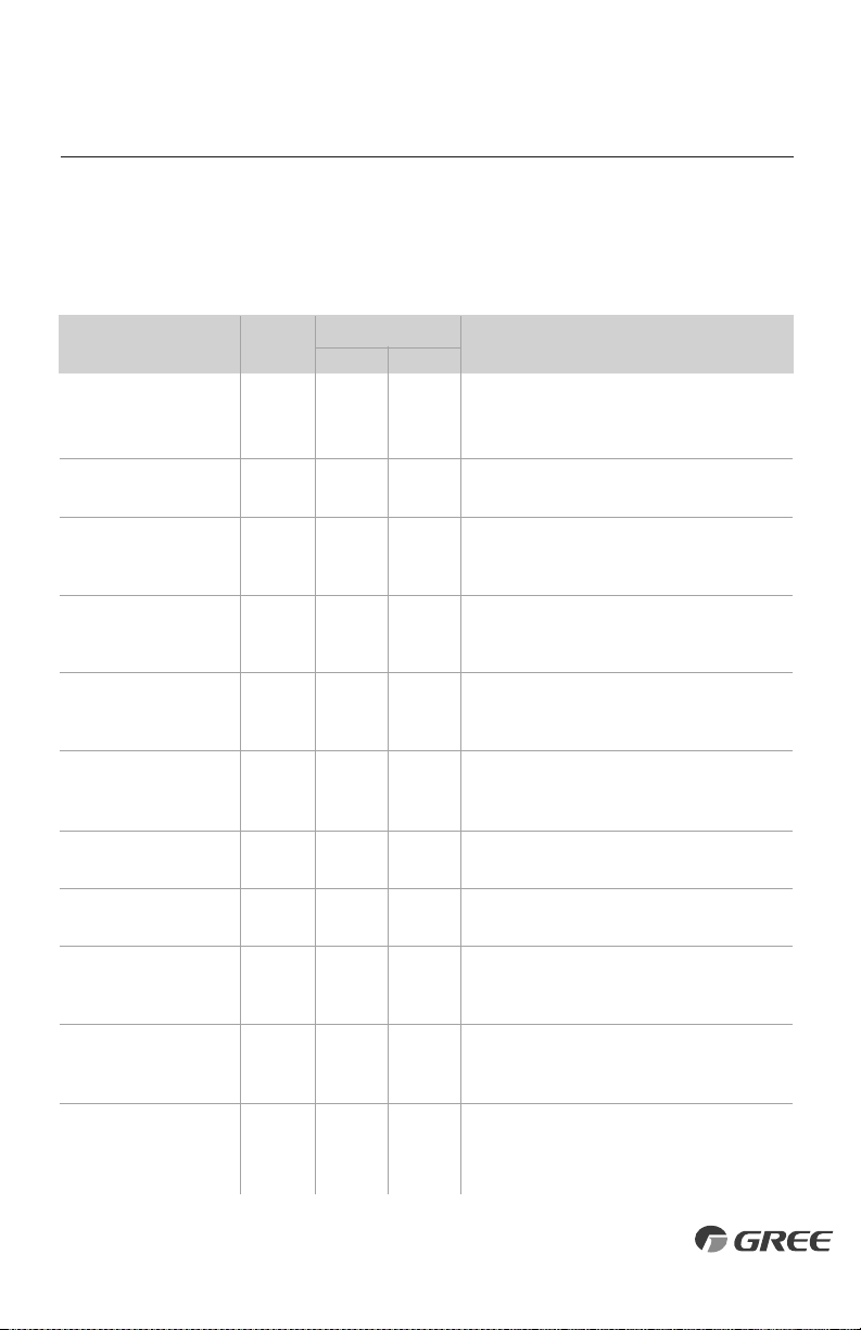
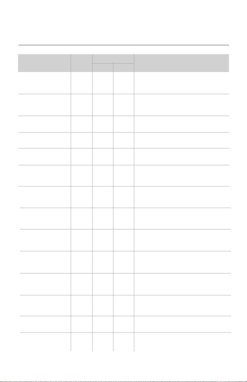
Troubleshooting
The unit has onboard diagnostics. The outdoor unit will provide status indicators. The Tether
controller will display error codes. The following is a summary of the codes with explanation:
Tether
C
ontrol
Display
O
utdoor Unit Indicators
Malfunction Name Possible Causes
26
Outdoor Unit Indicators
M
alfunction Name Possible Causes
DIAGNOSTIC CODES
H
igh Temperature
R
esistant Protection
Cold Air Protection
EEPROM Memory Malfunction
Module Phase Current Protection -
Frequency Decrease/Limit Mode
Module Temperature Protection -
Frequency Decrease/Limit Mode
Refrigerant Leakage Protection
Indoor Ambient Temperature
Sensor Malfunction
Indoor Coil Temperature
Sensor Malfunction
Outdoor Ambient Temperature
Sensor Malfunction
Outdoor Coil Temperature
Sensor Malfunction
Outdoor Discharge Temperature
Sensor Malfunction
Compressor Overload Protection -
Frequency Decrease/Limit Mode
Oil Return Protection - Frequency
Decrease/Limit Mode
System Current Overload Protection -
Frequency Decrease/Limit Mode
1
) Incorrect refrigerant charge level
2
) Refrigerant metering device malfunction
3
) Compressor malfunction
1) Indoor coil has not reach minimum heating temperature
2) Indoor ambient is abnormally cold
3) Indoor control board malfunction
Control board malfunction
Outdoor control board malfunction
1) IPM module over heating or malfunctioning
2) Improper voltage at IPM Module
1) refrigerant leak(s)
2) Indoor coil temperature sensor no calibrated
3) Refrigerant flow is restricted ( ex. valve, exv, debris)
1) Loose or bad connection between sensor and control board
2) Indoor ambient temperature sensor damaged
3) Control board malfunction
1) Loose or bad connection between sensor and control board
2) Indoor coil temperature sensor damaged
3) Control board malfunction
1) Loose or bad connection between sensor and control board
2) Outdoor ambient temperature sensor damaged
3) Control board malfunction
1) Loose or bad connection between sensor and control board
2) Outdoor coil temperature sensor damaged
3) Control board malfunction
1) Loose or bad connection between sensor and control board
2) Discharge temperature sensor damaged
3) Control board malfunction
1) Incorrect refrigerant charge
2) Metering device malfunction
3) Compressor malfunction
Normal function status code only
1) Input voltage too low
2) System pressure too low
E8
E9
EE
En
EU
F0
F1
F2
F3
F4
F5
F6
F7
F8
Y
ellow
6
flashes
a
nd 1 sec Off
11 flashes
and 1 sec Off
R
ed
11 flashes
and 1 sec Off
9 flashes
and 1 sec Off
6 flashes
and 1 sec Off
5 flashes
and 1 sec Off
7 flashes
and 1 sec Off
3 flashes
and 1 sec Off
1 flashes
and 1 sec Off
T
ether
Control
Display
27
Outdoor Unit Indicators
M
alfunction Name Possible Causes
DIAGNOSTIC CODES
High Compressor Discharge
Temperature - Frequency
Decrease/Limit Mode
Indoor Coil Freeze Protection -
Frequency Decrease/Limit Mode
Pump Down or Gathering
Refrigerant Status
Defrost Mode in Heating
Compressor Overload Protection
IPM Module Protection
Indoor DC Fan Motor
Malfunction
Compressor De-Synchronized
Malfunction
Power Factor Correction (PFC)
Protection
Compressor Demagnetization
Protection
High Input Power Protection
Start-Up Malfunction
Compressor phase-lacking/
phase-inverse protection
1) Cooling load is too great
2) Outdoor ambient temperature too high
3) Refrigerant charge too low
4) Metering device malfunction
1) Indoor coil has not reach minimum heating temperature
2) Indoor ambient is abnormally cold
3) Indoor control board malfunction
Optional Service Mode
Operation status
1) Wiring terminal OVC-COMP is loose
2) Refer to the malfunction analysis in Service Manual
1) IPM module over heating
2) Improper or Low voltage at the IPM module
3) IPM module malfunction
1) Loose connections between fan motor and control board
2) Fan motor or blower wheel bearings malfunction
3) Control board malfunction
1) Compressor voltage is not balance
2) Control board malfunction
3) Compressor malfunction
1) Mis-wiring of the reactor filter and PFC capacitor
2) Reactor filter or PFC capacitor malfunction
3) Control board malfunction
Compressor malfunction
1) Compressor malfunction
2) Power circuit malfunction
1) Over charged with refrigerant
2) Control board malfunction
3) Compressor malefaction
Hardware malfunction
F9
FH
Fo
H1
H3
H5
H6
H7
HC
HE
L9
LC
Ld
Y
ellow
2 flashes and
1 sec Off
17 flashes
and 1 sec Off
8 flashes
and 1 sec Off
4 flashes
and 1 sec Off
14 flashes
and 1 sec Off
9 flashes
and 1 sec Off
R
ed
4 flashes
and 1 sec Off
T
ether
Control
Display
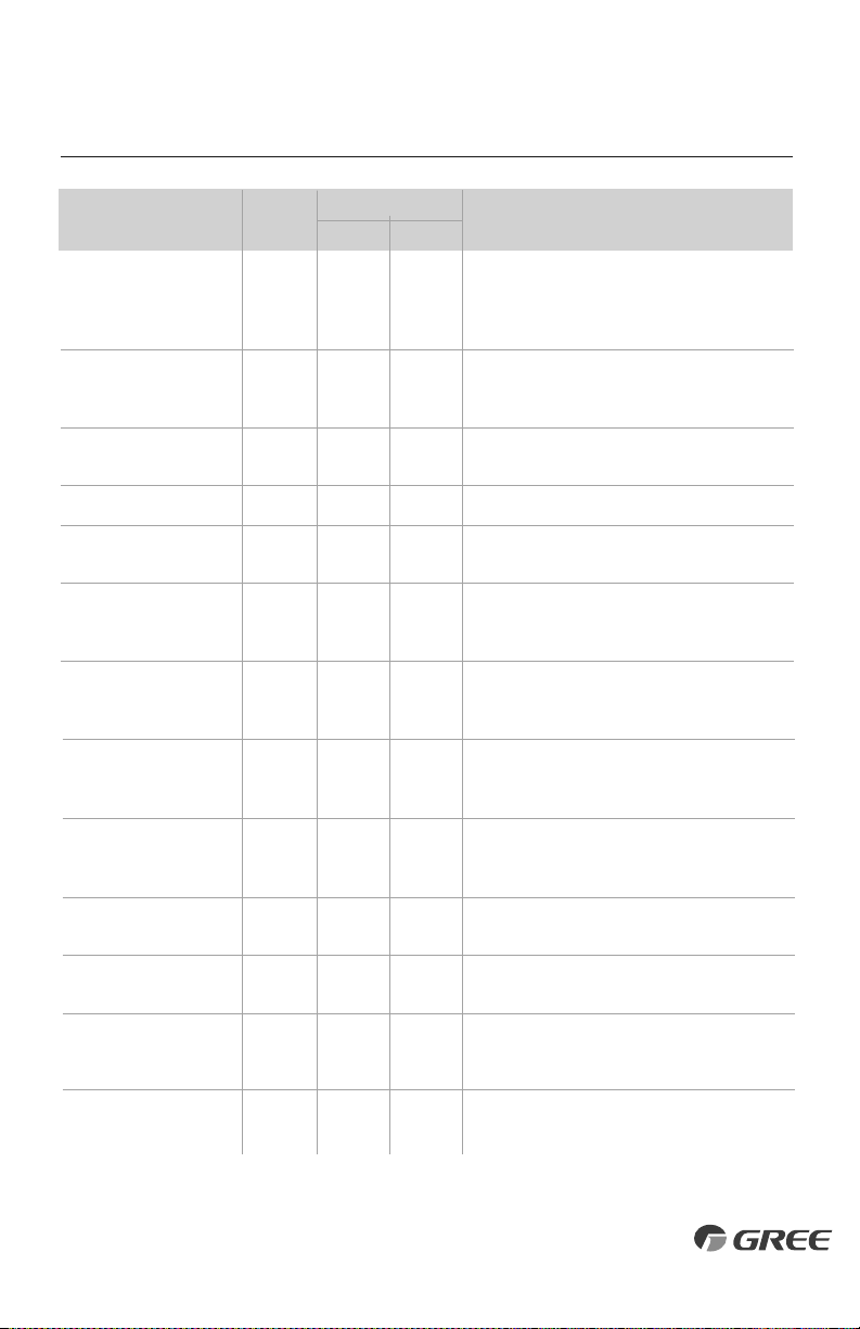
Notes: 1) During defrosting process, the heating indicator is on for 10s and off for 0.5s.
2) Refer to Service Manual for additional information.
Outdoor Unit Indicators
Malfunction Name Possible Causes
DIAGNOSTIC CODES
Incompatible Indoor and
Outdoor Units
Compressor Phase Current
P
rotection
Module Temperature Sensor
Malfunction
Module Temperature Protection
High DC Bus Voltage Protection
Low DC Bus Voltage Protection
Capacitor Charging Malfunction
Compressor Phase-Current
Detection Malfunction
DC Bus Voltage Dip
Input Current Detection Malfunction
The four-way valve is abnormal
Zero cross detection circuit
malfunction(for indoor unit)
Indoor and outdoor units are not compatible
1) IPM module malfunction
2
) Outdoor control board malfunction
3) Compressor malfunction
Outdoor control board malfunction
1) Lack of thermal grease on IPM module
2) Heat sink (radiator) not tightly mounted
3) Control board malfunction
1) Supply voltage on L1 and N is above 265Vac
2) Capacitor on control board malfunction
3) Outdoor control board malfunction
1) Supply voltage on L1 and N is below 150Vac
2) Capacitor on control board malfunction
3) Outdoor control board malfunction
Capacitor malfunction
Outdoor control board malfunction
Outdoor control board malfunction
Outdoor control board malfunction
Hardware malfunction
Hardware malfunction
L
P
P5
P7
P8
PH
PL
PU
U1
U3
U5
U7
U8
Y
ellow
16 flashes
and 1 sec Off
13 flashes
and 1 sec Off
12 flashes
and 1 sec Off
R
ed
28
T
ether
C
ontrol
D
isplay

ENERGY SAVING TIPS
1. Relaxing room temperature at night is OK: During the nighttime hours you
don't require the same level of conscious cooling or heating. Try using Sleep Mode to
gradually relax room temperature and allow the unit to run less and save energy.
2. Curtains and shades: In the summer, you need to block the effects of the sun.
Close window curtains and shades on the south and west side of your home to help
block solar heat. In winter, the sun is your friend. Open curtains and shades to allow
solar heat into your room.
3. Close doors: If you don’t need to heat and cool your whole home, confine the heating
and cooling to one room by closing doors. Limit the space you’re heating and cooling
to specified capability of the unit.
4. Service the unit: Some basic maintenance might be all you need. The outdoor unit
will greatly benefit from a good hosing out, especially in treed areas where seeds and
other debris can stick to coil fins and make the unit work up to 15% harder!
5. Rearrange the room: Furniture that obstructs airflow means you could be heating
and cooling the back of a chair or the front of a sofa instead of the actual living space.
Remove or rearrange obstacles blocking airflow.
6. Try 75 degrees: 75 °F is a good point for an air conditioner to run at its optimal
performance level. Even a 5-degree change in temperature can make your unit use
up to 40% more energy!
7. Lighting: Turning lights off can help reduce your heat. Each light bulb is a tiny heater.
Your air conditioner must waste energy overcoming the heat from your lights to reach
and hold your desired room temperature.
8. Is anyone home? If possible, while you're away turn your unit to Auto mode and
make sure windows and drapes are closed. Although room temperature may be less
than optimal for a few minutes when you come home, the unit will soon have the
room back to your desired temperature.
9. Don't forget the fan: The fan is much like a car. The faster it runs, the more energy it
uses. Sometimes we need the car to go fast, but slow is good enough most of the time.
Try saving money by using the comfortable quiet low fan speed as much as possible.
29
LIMITED WARRANTY STATEMENT
GREE distributor (hereinafter “Company”) warrants this product against failure due to defect in materials or workmanship under normal use and maintenance as
follows. All warranty periods begin on the date of original installation. If the date cannot be verified, the warranty period begins one hundred twenty (120) days
from date of manufacture. If a part fails due to defect during the applicable warranty period, Company will provide a new or remanufactured part, at Company’s
option, to replace the failed defective part at no charge for the part. This limited warranty is subject to all provisions, conditions, limitations and exclusions listed
below.
LIMITATIONS OF WARRANTIES:
ALL IMPLIED WARRANTIES AND/OR CONDITIONS (INCLUDING IMPLIED WARRANTIES OR CONDITIONS OF
MERCHANTABILITY
AND FITNESS FOR A PARTICULAR USE OR PURPOSE) ARE LIMITED TO THE DURATION OF THIS LIMITED WARRANTY, SOME STATES DO NOT
ALLOW
LIMITATIONS ON HOW LONG AN IMPLIED WARRANTY OR CONDITION LASTS, SO THE ABOVE MAY NOT APPLY TO YOU. THE EXPRESS WARRANTIES
MADE IN THIS
WARRANTY ARE EXCLUSIVE AND MAY NOT BE ALTERED, ENLARGED, OR CHANGED BY ANY DISTRIBUTOR, DEALER, OR OTHER PERSON,
WHATSOEVER.
THIS WARRANTY DOES NOT COVER:
1. Labor or other costs incurred for diagnosing, repairing, removing, installing, shipping, servicing or handling of either defective parts, or
replacement parts, or new units.
2. Product cleaning required prior to warranty service and repair.
3. Normal maintenance as outlined in the installation and servicing instructions or Owner’s Manual,including filter cleaning and/or replacement
and lubrication.
4. Failure due to faulty installation or repairs, damage, misapplication, abuse, improper servicing, lack of or insufficient maintenance, unauthorized
alteration or improper operation.
5. Failure to start due to voltage conditions, blown fuses, open circuit breakers, or damages due to the inadequacy or interruption of electrical service.
6. Failure or damage due to floods, winds, fires, lightning, accidents, corrosive environments(rust or residue etc.) or other conditions beyond the
control of the Company.
7. Failure or damage of coils, piping or other parts due to corrosion, when installed within one (1) mile of sea coast or corrosive body.
8. Parts not supplied or designated by Company, or damages resulting from their use.
9. Products installed outside the 48 contiguous United States, except the District of Columbia and Hawaii.
10. Electricity or fuel costs, or increases in electricity or fuel costs from any reason whatsoever, including additional or unusual use of supplemental
electric heat.
11. Any cost to replace, refill or dispose of refrigerant, including the cost of refrigerant.
12. Shipping damage or damage as a result of transporting the unit.
13. Accessories such as condensate pumps, line sets and so forth are not covered.
14. Any special, indirect or consequential property or commercial damage of any nature whatsoever. Some states do not allow the exclusion of
incidental or consequential damages, so the above limitation may not apply to you.
15. Consumable components, such as air filters, are not covered under parts warranty.
This warranty gives you specific legal rights, and you may also have other rights which vary from state to state.
FOR WARRANTY SERVICE OR REPAIR: Contact your installing contractor. You may
find the installer’s name on the equipment or in your Owner’s packet or on your
invoice.
ONLINE REGISTRATION IS AVAILABLE AT: www.greecomfort.com/resources/
product-warranty/
Or complete product registration below:
• A warranty period of Five (5) years on all parts to the original registered end user when installed in a residential application.
• A warranty period of One (1) year on all parts to the original registered end user, when installed in commercial applications.
• A warranty period of 90 days on remote controls from purchase date.
• Limited warranty applies only to systems that are properly installed by a state certified or licensed HVAC contractor, under applicable local
and state law in accordance with all applicable building codes and permits; GREE installation and operation instructions and good trade
practices.
• Warranty applies only to products remaining in their original installation location.
• Defective parts must be returned to the distributor through a registered servicing dealer for credit.
Email completed form* to: [email protected]
or
Send copy of completed form* to:
Gree Warranty Registration
14610 Breakers Dr.
Jacksonville, FL 32258
* Keep copy of completed form for your files.
PRODUCT REGISTRATION
Indoor Model No:
Outdoor Model No:
Owner Name:
Installing Contractor:
Address of Installation:
Serial No:
Serial No:
Date of Installation:
Address:
Phone No. / Email:
CAT NO: GREE_MULTI_DUCT_A_OWNERS_050219
$
GREE