
Loading ...
Loading ...
INSTALLATION INSTRUCTIONS
This heater must be permanently installed and hard wired by a licensed electrician in accordance with local electrical
codes. Assembly procedure must be performed with no electrical power to unit.
Step 1: Check UL/CUL/CE label on heater for proper voltage.
Step 2: Follow supplied wiring instructions. (See wiring instructions below)
Step 3: Heater must be mounted with refl ector angled down.
Step 4: All electrical connections must be in compliance with the National Electric Code (NEC) and local codes for
outdoor wiring.
Step 5: Use only wiring components UL/CUL/CE listed for outdoor use with IPX4 minimum rating.
3
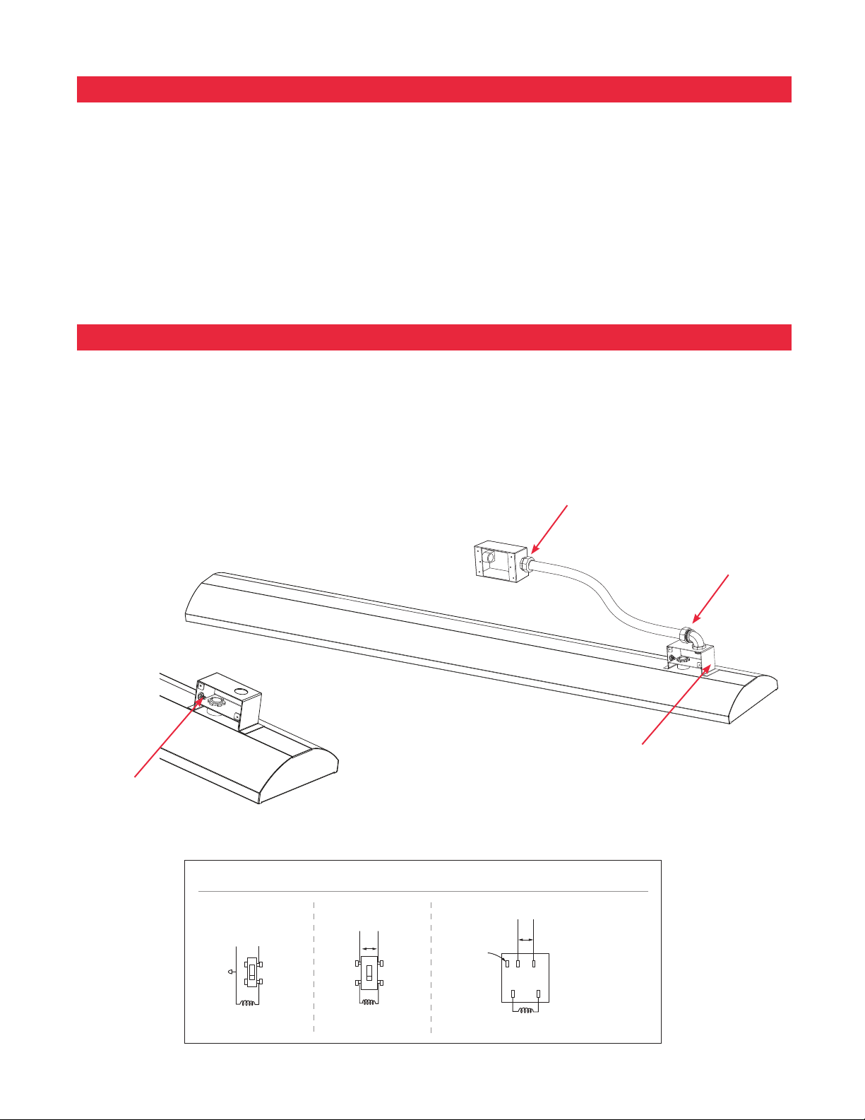
WIRING INSTRUCTIONS
The heater is drilled and threaded for standard 1/2" conduit fi ttings. The installing electrician will need to provide the
appropriate rigid metallic, fl exible or liquid tight conduit for the installation location.
• Observe local electrical code regulations.
• Remove cover plate from junction box.
• Attach conduit.
• Use only copper wire suitable for 90°C.
• Replace cover plate.
Connect power with fl exible
conduit or appropriate cord to
allow heater to be swiveled.
Junction Box on top of the heater
has a gasket side access cover.
The Junction Box inlet hole is
sized for a standard ½” weather
tight conduit fi tting and has a
locknut located on the inside of
the box for fastening.
GREEN GROUND
WIRE SCREW
TYPICAL WIRING OPTIONS
HEATING ELEMENT
OFF
ON
OFF
ON
HEATER
TOP
P L1 L2
H2H1
HEATER
FOR 115V. PILOT
LIGHT IF USED
11/32" (0.9 CM) INSIDE NUT
SNUG TO CERAMIC
11/32" (0.9 CM) OUTSIDE NUT
REAR VIEW OF
CONTROLLER FOR
MAX. 15 AMP
LOAD ONLY
"TOP" MARKED ON
REAR OF CONTROL
MUST BE INSTALLED
IN AN UP POSITION
240 V.
240 V.
WHITE
BLACK 115 V.
TYPICAL 120V WIRING
FOR A SINGLE POLE SWITCH
TYPICAL 240V WIRING FOR
A TWO POLE SWITCH
WIRING FOR OPTIONAL 120V/240V CONTROLS
Loading ...
Loading ...
Loading ...