Write Model and Serial Numbers here:
Model _________________________
Serial No. ______________________
FELIX STORCH, INC.
Summit Appliance Division
An ISO 9001:2015 registered company
770 Garrison Avenue
Bronx, New York
www.summitappliance.com
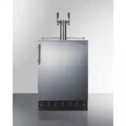
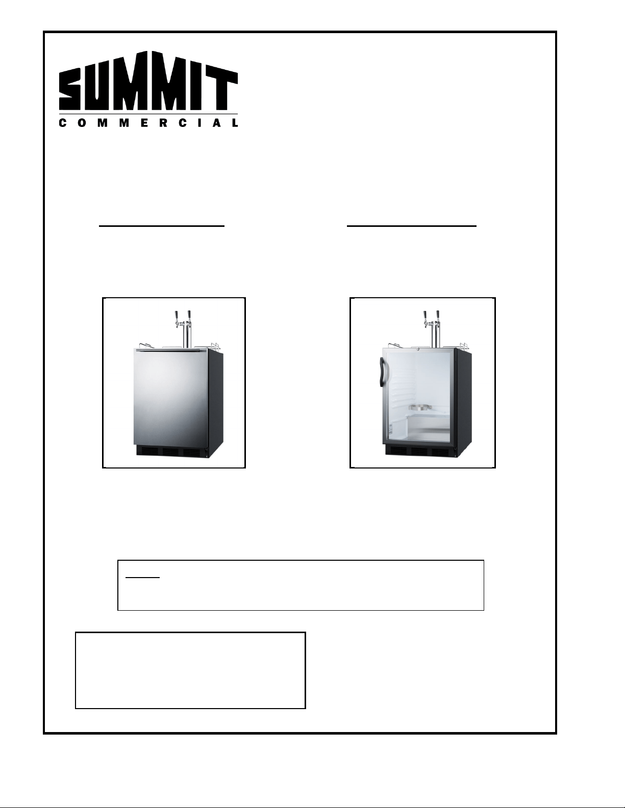
BUILT-IN UNDERCOUNTER COMMERCIAL
DUAL-TAP KEGERATORS
Solid Door Models: Glass Door Models:
SBC58BLBIADA Series SBC56GBIADA Series
SBC58WHBIADA Series SBC56GWBIADA Series
SBC7BRS Series
Instruction Manual
BEFORE USE, PLEASE READ AND FOLLOW
ALL SAFETY RULES AND OPERATING INSTRUCTIONS
NOTE: These units are designed for the cooling and dispensing
of beverages only and are not recommended for storing
perishable foods such as meats or dairy products.
2
IMPORTANT SAFEGUARDS
Your safety and the safety of others are very important.
We have provided many important safety messages in this manual and on your appliance. Always read and obey
all safety messages.
This is the Safety Alert Symbol. This symbol alerts you to potential hazards that can kill or
injure you and others. All safety messages will follow the Safety Alert Symbol and either
the words DANGER or WARNING.
DANGER means that failure to heed this safety
statement may result in severe personal injury or death.
WARNING means that failure to heed this safety
statement may result in extensive product damage,
serious personal injury, or death.
Safety messages will alert you to what the potential hazard is, tell you how to reduce the chance of injury, and
let you know what can happen if the instructions are not followed.
Before the kegerator is used, it must be properly positioned and installed as described in
this manual, so read the manual carefully. To reduce the risk of fire, electrical shock or
injury when using the appliance, follow basic precautions, including the following:
Plug into a grounded 3-prong outlet. Do not remove grounding prong, do not use an adapter, and do not use
an extension cord.
It is recommended that a separate circuit, serving only your kegerator, be provided. Use receptacles that
cannot be turned off by a switch or pull chain.
Never clean appliance parts with flammable fluids. These fumes can create a fire hazard or explosion. And
do not store or use gasoline or other flammable vapors and liquids in the vicinity of this or any other
appliance. The fumes can create a fire hazard or explosion.
Before proceeding with cleaning and maintenance operations, make sure the power line of the unit is
disconnected.
Do not connect or disconnect the electric plug when your hands are wet.
Unplug the appliance or disconnect the power before cleaning or servicing. Failure to do so can result in
electrical shock or death.
Do not attempt to repair or replace any part of your kegerator unless it is specifically recommended in this
material. All other servicing should be referred to a qualified technician.
DANGER – RISK OF FIRE OR EXPLOSION. FLAMMABLE RFRIGERANT
USED. TO BE REPAIRED BY TRAINED SERVICE PERSONNEL. DO
NOT PUNCTURE REFRIGERANT TUBING.
3
These appliances are CFC- and HFC-free and contain a small quantity of Isobutane (R600a) which is
environmentally friendly, but flammable. It does not damage the ozone layer, nor does it increase the
greenhouse effect. Care must be taken during transportation and setting up of the appliance that no parts of
the cooling system are damaged. Leaking coolant can ignite and may damage the eyes.
In the event of any damage:
- Avoid open flames and anything that creates a spark,
- Disconnect from the electrical power line,
- Air the room in which the appliance is located for several minutes and
- Contact the Service Department for advice.
The more coolant there is in an appliance, the larger the room it should be installed in. In the event of a leakage,
if the appliance is in a small room, there is the danger of combustible gases building up. For every ounce of
coolant at least 325 cubic feet of room space is required. The amount of coolant in the appliance is stated on
the rating label. It is hazardous for anyone other than an Authorized Service Person to carry out servicing or
repairs to this appliance.
Take serious care when handling, moving, and using the appliance to avoid either damaging the refrigerant
tubing or increasing the risk of a leak.
Replacing component parts and servicing shall be done by factory authorized service personnel so as to
minimize the risk of possible ignition due to incorrect parts or improper service.
Use two or more people to move and install the appliance. Failure to do so can result in back or other injury.
To ensure proper ventilation for your appliance, the front of the unit must be completely unobstructed.
Choose a well-ventilated area with temperatures above 60
°
F (16
°
C) and below 90
°
F (32
°
C). This unit must be
installed in an area protected from the elements, such as wind, rain, water spray or drips.
The appliance should not be located next to ovens, radiators or other sources of high heat.
The appliance must be installed with all electrical connections in accordance with state and local codes. A
standard electrical supply (115V AC only, 60 Hz), properly grounded in accordance with the National
Electrical Code and local codes and ordinances, is required.
Do not kink or pinch the power supply cord of the appliance.
The fuse (or circuit breaker) size should be 15 amperes.
It is important for the kegerator to be leveled in order to work properly. You may need to make several
adjustments to level it.
Never allow children to operate, play with or crawl inside the kegerator.
Do not use solvent-based cleaning agents or abrasives on the interior. These cleaners may damage or
discolor the interior.
Do not use this apparatus for other than its intended purpose.
THESE MODELS ARE DESIGNED FOR COMMERCIAL USE.
Risk of child entrapment
Child entrapment and suffocation are not problems of the past. Junked or abandoned refrigerators and
freezers are still dangerous, even if they will “just sit in the garage a few days.”
Before you throw away your old refrigerator or freezer: Take off the doors. Leave the shelves or
drawers in place so that children may not easily climb inside.
Never allow children to operate, play with, or crawl inside the refrigerator/freezer.
THIS APPLIANCE IS NOT INTENDED FOR USE BY YOUNG CHILDREN OR INFIRM PERSONS UNLESS
THEY HAVE BEEN ADEQUATELY SUPERVISED BY A RESPONSIBLE PERSON TO ENSURE THAT THEY
CAN USE THE APPLIANCE SAFELY. YOUNG CHILDREN SHOULD BE SUPERVISED TO ENSURE THAT
THEY DO NOT PLAY WITH THE APPLIANCE.
– SAVE THESE INSTRUCTIONS –

4
Table of Contents
Important Safeguards ...................................................................................................... 2-3
Location of Parts ............................................................................................................. 5-6
Technical Information .........................................................................................................7
Installation Instructions ................................................................................................ 8-21
Parts List ........................................................................................................................8
Before Using Your Appliance ..........................................................................................8
Installing the Kegerator ...................................................................................................8
Electrical Connection ......................................................................................................9
Extension Cord ...............................................................................................................9
Reversing the Door Swing ...................................................................................... 10-11
Adjusting the Tilt ........................................................................................................... 12
Draft Arm Assembly ...................................................................................................... 12
Beer Kegs and Keg Tappers ......................................................................................... 12
CO
2
Regulator and CO
2
Cylinder .................................................................................. 13
Installation of Beer Keg Tap Kit .............................................................................. 13-14
Installation of Cold Brew Tap Kit ............................................................................. 15-16
Installation of Wine Dispenser Tap Kit ..................................................................... 17-21
Operating Your Kegerator ................................................................................................. 22
Temperature Control
Defrosting
Care and Maintenance ....................................................................................................... 23
Cleaning Your Appliance / Power Failure / Vacations /
Moving your Appliance / Energy-Saving Tips
Draft Beer Troubleshooting ........................................................................................ 24-25
General Troubleshooting .................................................................................................. 26
Limited Warranty ............................................................................................................... 28
5
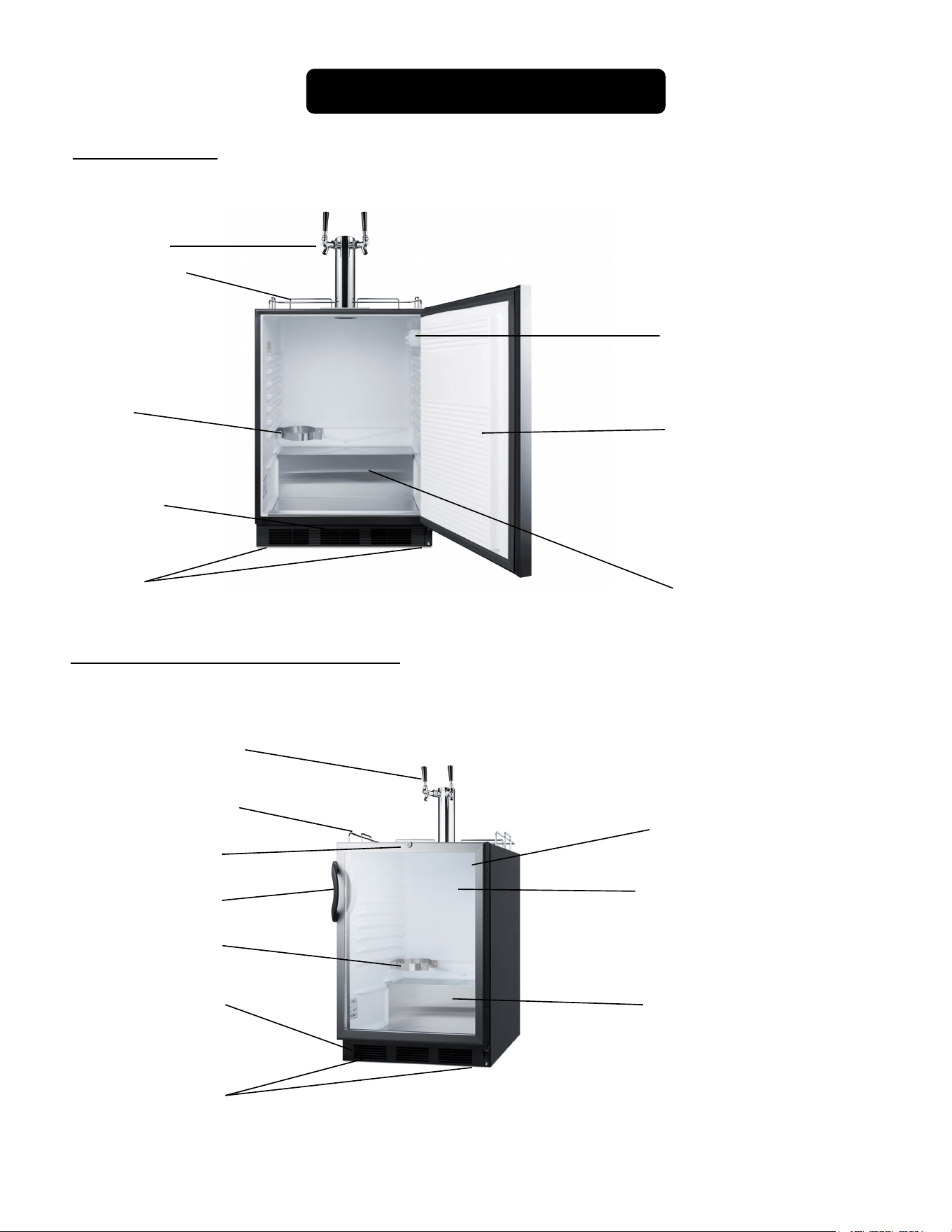
Location of Parts
Temperature control dial
(thermosta
t) and interior
light
Door
Front ventilation
slots (kick plate)
Leveling/adjustable
legs
Compressor
step
CO
2/
N canister
holder
Solid Door Series
Models SBC56G and SBC56GW Series
Temperature control dial
(thermosta
t),
light switch
and interior light
Glass door
Front ventilation
slots (kick plate)
Leveling legs
Compressor
step
Handle
Lock
Twin taps
(
style varies)
Twin taps
(Style
varies)
Railing
Railing
CO
2
canister
holder
6
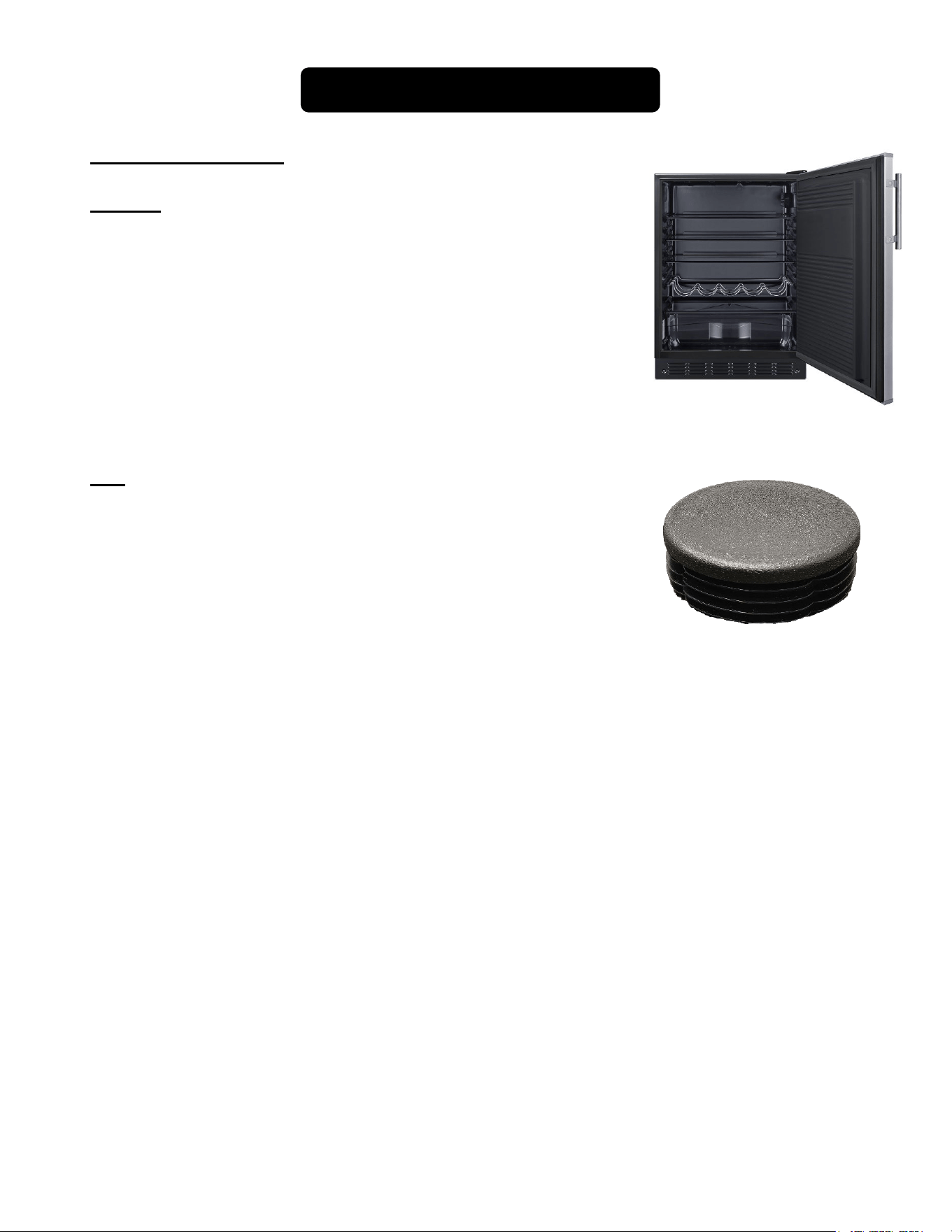
Location of Parts
For the SBC7RS Series: L
Shelves
Your unit comes with adjustable shelves, which can also be
removed should you decide not to use them. Save the shelves if you
wish to use your kegerator as a refrigerator.
Cap
Your unit will also include a cap on top of the unit. Remove this
cap when installing the tapping equipment. Save this cap if you
wish to convert your kegerator into a refrigerator.
7
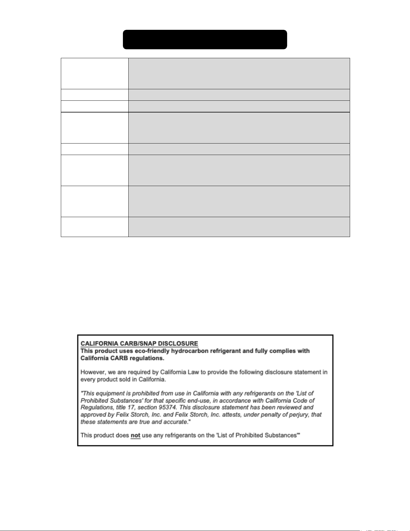
Technical Information
Model Numbers
and
Descriptions
SBC58 Series (solid door & white interior)
SBC56G Series (glass door & white interior)
SBC7BRS Series (solid door & black interior)
Capacity Two 1/6 kegs
Electrical Input 115V AC/60Hz
Rated Current
SBC58BL models:1.2A
SBC56G models: 1.8A
SBC7BRS models: .8A
Defrost
Automatic
Refrigerant
SBC58BL models: R600a (.64 oz.)
SBC56G models: R600a (.67 oz.)
SBC7BRS models: R600a (.64 oz.)
Installation
SBC58 Series: Built-In/Freestanding
SBC56G Series: Built-In/Freestanding
SBC7BRS Series: Recessed/Freestanding
Unit Dimensions
(W x D x H)
23.63" x 23.5" x 32.25” (ADA series) or 33” to 34.5” (RS Series)
NOTES: Models with “NK” in the suffix do not include tapping equipment.
All models are ETL-S listed to NSF-7 standards for commercial use.
Specifications are subject to change without notice.
Units with the suffix “RS” are height adjustable up to 34.5” and include a leg shield for optional use. This
is packaged behind the unit and can be placed in front of the legs to cover the gap that occurs between the unit
and your floor when raising the height. These units also include a set of four casters for optional installation. To
use, carefully tilt the kegerator on its side and unscrew the four legs. Replace the four casters, being sure to
install the two locking casters in the front.

8
Installation Instructions
Parts List
Remove all packing materials and parts. Inspect to make sure all parts listed below are
present and in good condition:
1 double draft arm assembly (with washer)
1 CO
2 or
Nitrogen cylinder
1 CO
2
or
Nitrogen regulator
2 keg taps (American Sankey type)
Vinyl tubing
1 stainless steel (removable) floor to protect the unit during keg insertion
1 drip tray
Hose clamps
4 casters (“RS” series only)
1 leg shield (“RS” series only)
Various screws
Before Using Your Appliance:
Remove the exterior and interior packing.
Before connecting the unit to a power source, let it stand for approximately 2 hours. This will
reduce the possibility of a malfunction in the cooling system from handling during transportation.
Clean the interior surfaces of the unit with lukewarm water using a soft cloth.
Installing the Kegerator:
Place the unit on a floor that is strong enough to support the appliance when it is fully loaded. To
level the unit, adjust the two leveling legs at the front.
Kegerators that begin “SBC58” or “SBC56” are designed for freestanding or built-in installation.
Kegerators that begin “SBC7RS” are designed for freestanding or recessed installation in a 24-inch
wide (minimum) opening. Please allow 2” clearance in the back and some airflow on the sides and
top of the units. Take care that the air vents at the front of the appliance are never covered or
blocked in any way.
Locate the unit away from direct sunlight and sources of heat (oven, heater, radiator, etc.). Direct
sunlight may affect the acrylic coating and heat sources may increase electrical consumption.
Extremely cold ambient temperatures may also affect the unit's performance.
Avoid locating the unit in moist areas. Too much moisture in the air will cause frost to form quickly
on the evaporator, requiring more frequent defrosting of the interior.
Plug the unit into an exclusive, properly installed and grounded wall outlet. Do not under any
circumstances cut or remove the third (ground) prong from the power cord. Any questions
concerning power and/or grounding should be directed toward a certified electrician or authorized
service center.
9
Improper use of the grounded plug can result in the risk of electrical shock. If the power
cord is damaged, have it replaced by the manufacturer, its service agent or similarly
qualified persons in order to avoid a hazard.
Electrical Connection:
This unit should be properly grounded for your safety. The power cord of this unit is equipped with a
three-prong plug which mates with a standard three-prong wall outlet to minimize the possibility of
electrical shock.
Do not under any circumstances cut or remove the third ground prong from the power cord supplied.
For personal safety, this appliance must be properly grounded.
This unit requires a standard 115-volt AC/60Hz electrical outlet with three-prong ground. Have the wall
outlet and circuit checked by a qualified electrician to make sure the outlet is properly grounded. When
a standard 2-prong wall outlet is encountered, it is your responsibility and obligation to have it
replaced with a properly grounded 3-prong wall outlet.
To prevent accidental injury, the cord should be secured behind the unit and not left exposed or
dangling.
The unit should always be plugged into its own individual electrical outlet which has a voltage rating
that matches the rating label on the appliance. This provides the best performance and also prevents
overloading house wiring circuits that could cause a fire hazard from overheated wires. Never unplug
the unit by pulling on the power cord. Always grip the plug firmly and pull straight out from the
receptacle. Repair or replace immediately any power cord that has become frayed or otherwise
damaged. Do not use a cord that shows cracks or abrasion damage along its length or at either end.
When moving the unit, be careful not to damage the power cord.
Extension Cord:
Do not use an extension cord with this appliance. If the power cord is too short, have a qualified
electrician or service technician install an outlet near the appliance.
10
Reversing the Door Swing
Select models in the SBC58/SBC7BRS/SBC56G series have user-reversible doors. Holes on the
opposite side have already been prepared at the factory.
By default, the door hinge is on the right side. If you prefer it on the left, please follow the appropriate
instructions:
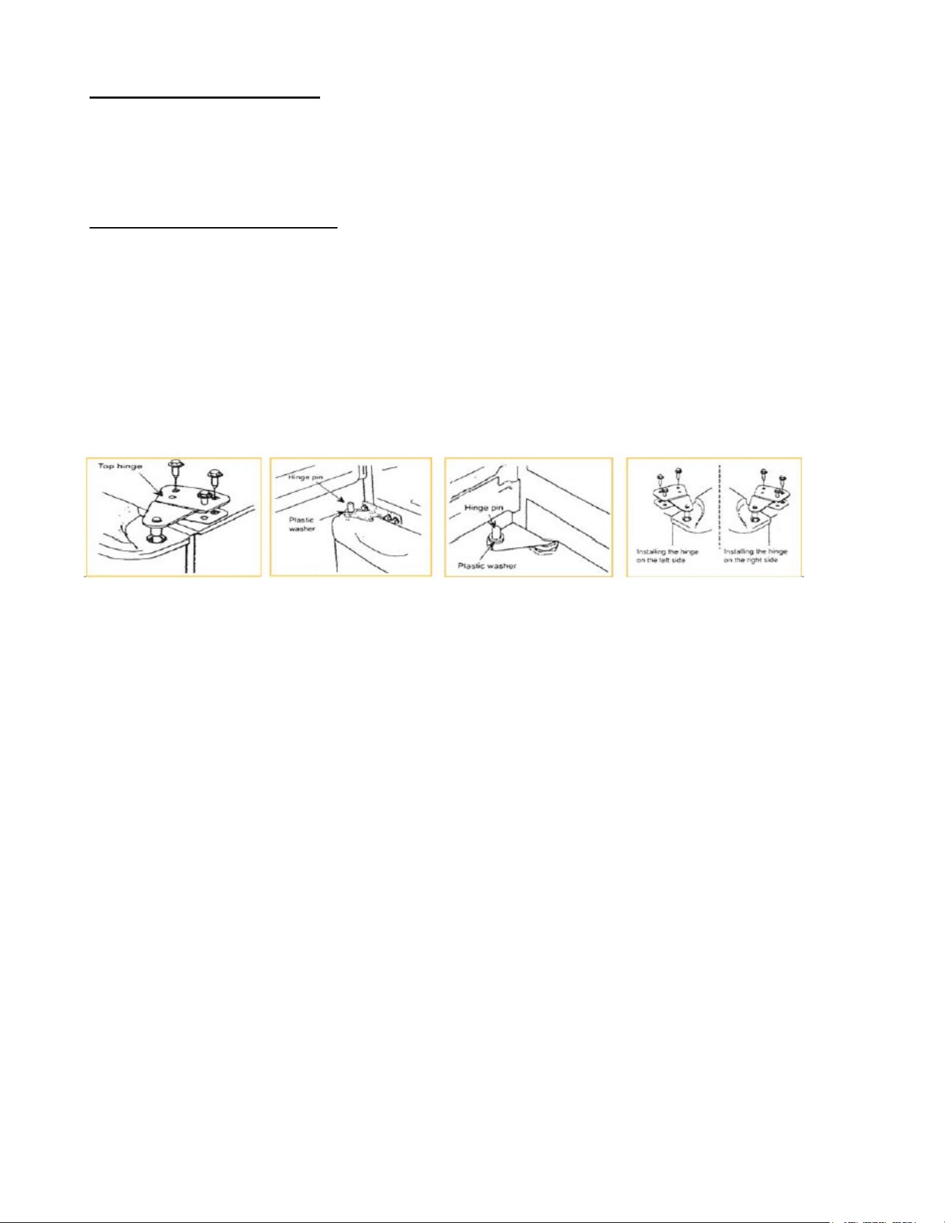
For SBC58/SBC7BRS models:
1. Take off the upper hinge cover from the door and remove the screws that hold the top hinge.
2. Lift the hinge straight up to free the hinge pin from the socket at the top of the door.
3. Lift the door up and away to free its bottom socket from the hinge pin.
4. Remove the screws to the bottom hinge.
5. Remove the decorative caps from the opposite side and plug the holes from the original side with
the decorative caps.
6. Move the bottom hinge to the opposite side and tighten the screws. Use any lock washers or nuts if
they were installed in the original installation.
7. Replace the door with the hinge pin on the bottom hinge. Place the top hinge pin into the door.
Insert screws into the top hinge and tighten.
If you notice the door is not hanging straight, loosen the top hinge screws, adjust the door until it is
leveled, and tighten the screws.
11
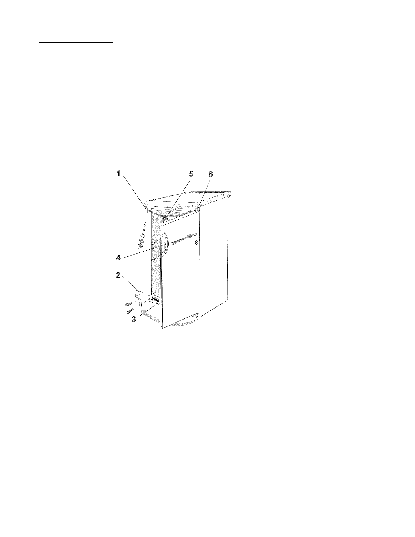
For SBC56G models:
NOTES: See the illustration below.
All of the parts that are removed must be kept for the reinstallation of the door.
1. Unscrew the lower hinge and take off the door.
2. Push the kick plate to the right in the new position.
3. Undo the upper hinge fastener and fix it to the opposite side of the housing, where you have
already removed and replaced the fastener with the hole to the opposite side
4. Put the door on the upper hinge fastener.
5. Fix the lower hinge in the new position.
6. Unscrew the handle and place it on the opposite side.
7. Some screws are covered with caps. Take off these caps before undoing the screws.
8. Check the door gasket. It should not be creased and should seal well.
1. Upper hinge fastener 4. Handle
2. Lower hinge 5. Door hinge fixture
3. Kick plate 6. Door hinge fixture plug
NOTE: The direction of the door swing for “CSS” and “IF” models is not reversible by the user.
12
Adjusting the Tilt
If your beer cooler seems unsteady or you would like the door to close more easily, you can use the
leveling legs to adjust the tilt of the unit.
Be sure that the unit is in its final position when adjusting the tilt and that it is plugged into a
grounded 3-prong outlet.
WARNING:
Two or more people are required to move and/or install the refrigerator. Failure
to do so may cause back or other injury.
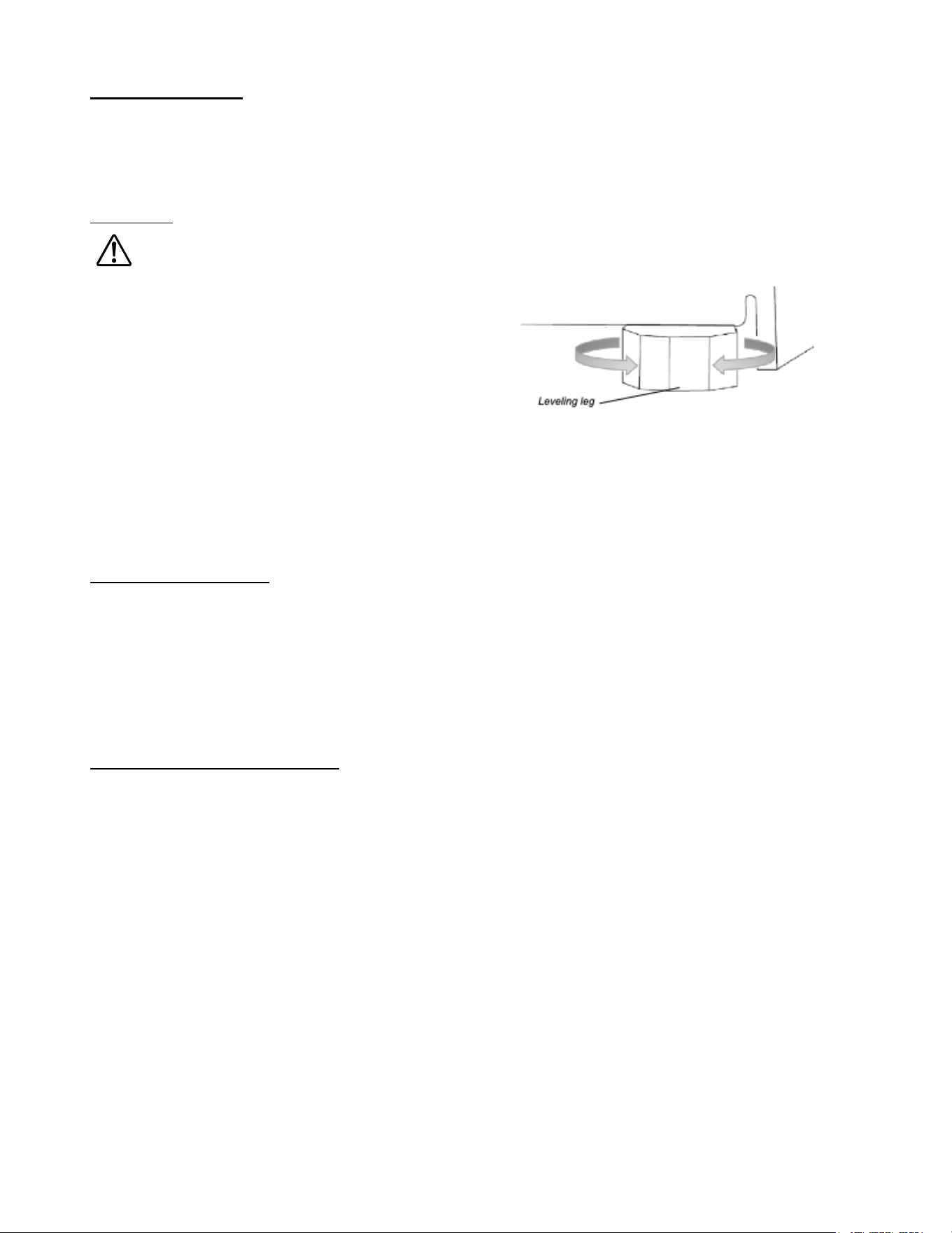
Turning a leveling leg to the right will lower the
appliance toward the position of the leg. Likewise,
turning to the left will raise the unit away from the
leg.
Several turns of the leveling legs may be required
before the tilt of the appliance is properly
adjusted.
Turning both front legs an equal amount to the left will tilt the kegerator towards the rear. This
adjustment makes it easier for the door to close.
NOTE: It is easier to adjust the leveling legs if someone else pushes against the top of the
appliance to take the weight off the legs.
Draft Arm Assembly
1. Slide the gasket over the wing nut on the bottom of draft arm assembly beer tubes. Slide gasket
up beer tubes to draft arm base.
2. Push the wing nut on the beer tube of the draft arm assembly through the hole in the top of the
cabinet until the draft arm is resting on cabinet top.
3. Align holes in draft arm base with holes in gasket and pilot holes in cabinet, then secure the guard
rail to the cabinet top.
Beer Kegs and Keg Tappers
Your kegerator cooler comes with a double tap and will accommodate two “Sixth Barrel” kegs, also
known as “sixtels” or “logs”. Each sixtel has a height of 23-3/8” and a diameter of 9-1/4” and hold 5.16
gallons of beer. Two Cornelius (“Corny”) kegs will also fit. The unit will not hold a half barrel or quarter
barrel, although it can take one “Slim Quarter” barrel.
The Sankey type keg tappers supplied with the kegerator are the most widely used in the United
States.
However, other types of keg tappers can be used. Before installing a keg tapper, check with your
beer distributor to make sure that the Sankey type keg tapper can be used.
If you need keg tappers other than the Sankey type, it is recommended that you purchase the tappers
you need from your beer distributor. Please keep the Sankey type keg tappers for future use. The
Sankey system is becoming more popular. It may be purchased from our sales Department at 718-
893-3900.
13
CO
2
Regulator and CO
2
Cylinder
NOTE: Your CO
2
cylinder is shipped empty to avoid any possible accidents during transportation.
When you purchase the first keg of beer, have your beer distributor fill the CO
2
cylinder. You must
read and understand the following procedures for CO
2
cylinders before installation:
1. Install the CO
2
gas line tube to the regulator by attaching one end of the red tube to the hose
connection on the CO
2
regulator.
2. Secure the tube by using one of the self-locking black plastic snap-on clamps.
3. Insert a special washer into the regulator-to-cylinder attachment nut.
4. Attach the CO
2
regulator to the CO
2
cylinder by screwing the regulator nut onto the cylinder valve
and tightening with an adjustable wrench.
5. Remove the bolt with the nut from the cylinder retainer. Using two screws, attach it inside the unit
on the left side of the back wall. Holes are pre-drilled, and screws are included.
6. Slide the cylinder through the retainer and secure it with the bolt and the nut. Position the cylinder
this way so that you will be able to read the numbers on the gauges and easily access the shut-off
valve.
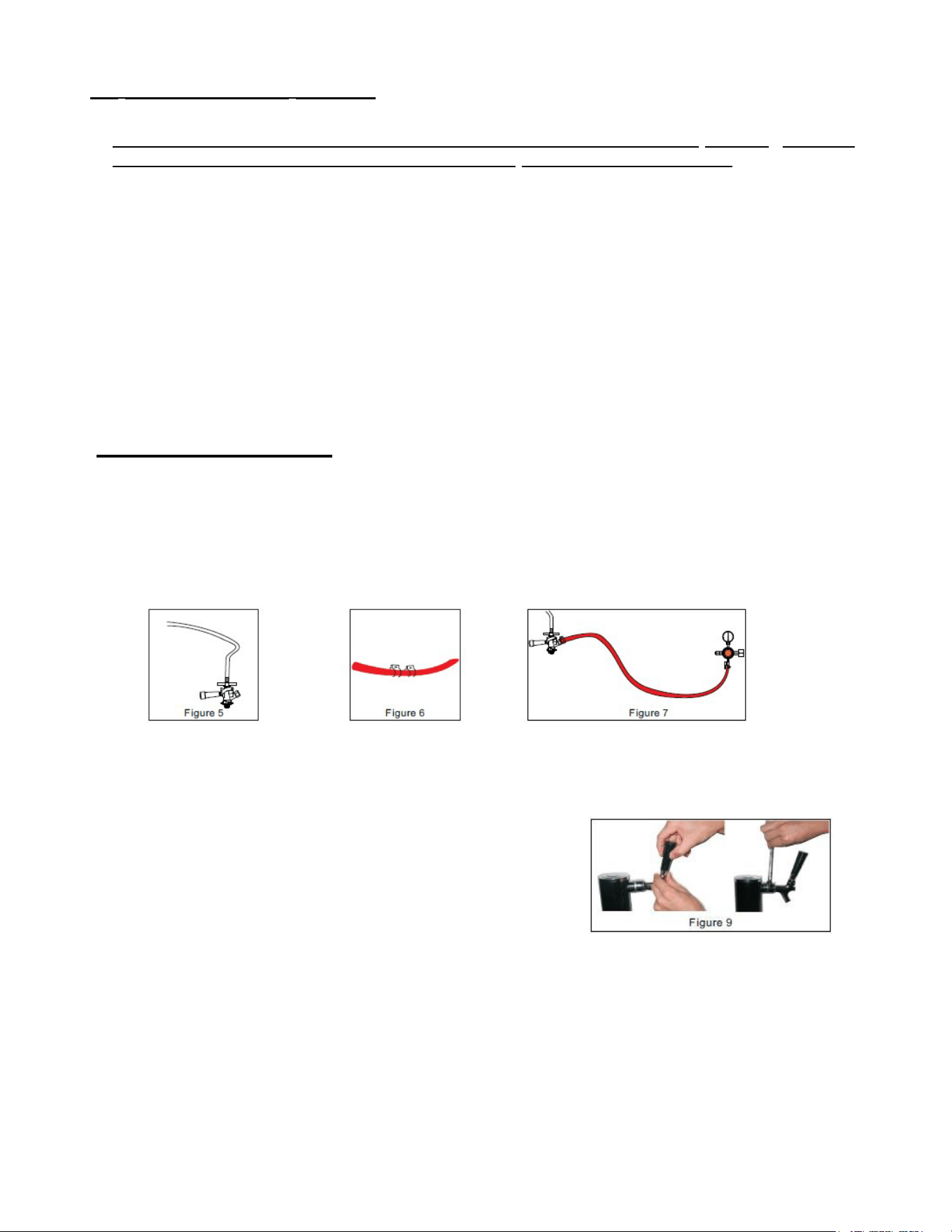
Installation of Accessories
1.
Once the unit has been positioned under the counter, install the beer tower assembly and the
mixed ball valve:
a.
Lower the beer tower through the hole in the counter and into the hole at the top of the beer
dispenser’s
upper surface. Be sure the tap is facing toward the front of the machine.
b.
Take out the accessories of the mixed ball valve. Attach the transparent hose to the beer
outlet of the
mixed ball valve. (See Figure 5).
2.
Install CO
2
gas cylinder and CO
2
regulator valve:
a.
Fix the two CO
2
hose clamps on the red CO
2
tube (See Figure 6).
b.
Connect the ends of the red CO
2
tube respectively to the CO
2
intake port of the mixed ball
valve and the
round outlet of the CO
2
regulator valve.
Lock these connections firmly with the two clamps on the
red CO
2
tube (See Figure 7).
c.
Using the wrench, tighten the CO
2
regulator table valve
with the hex nut port to the gas outlet of the CO
2
tank
(See Figure 9).
14
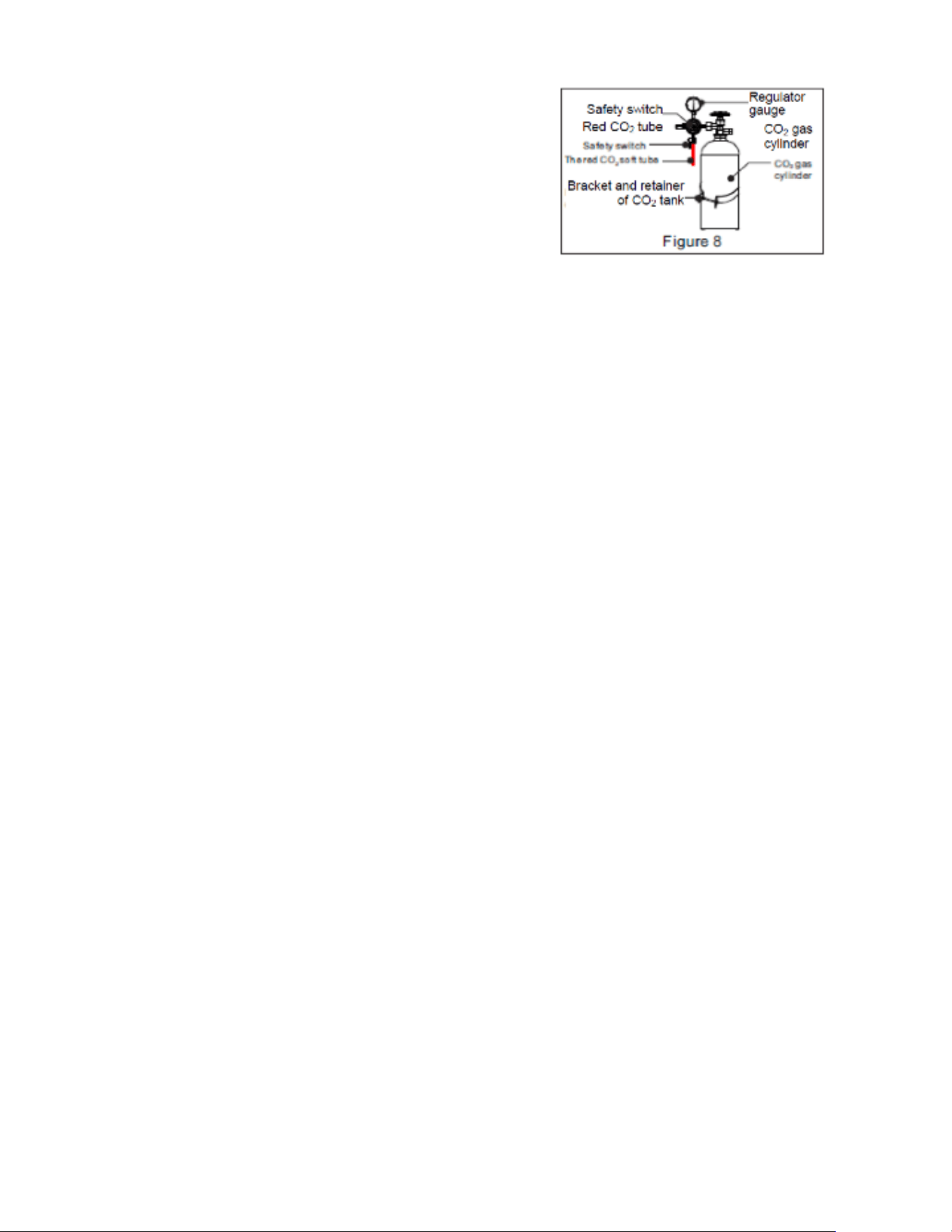
d.
Place the CO
2
tank and CO
2
regulator valve
component into the cabinet and fix the CO
2
tank
with
tank bracket and retainer (See Figure 8).
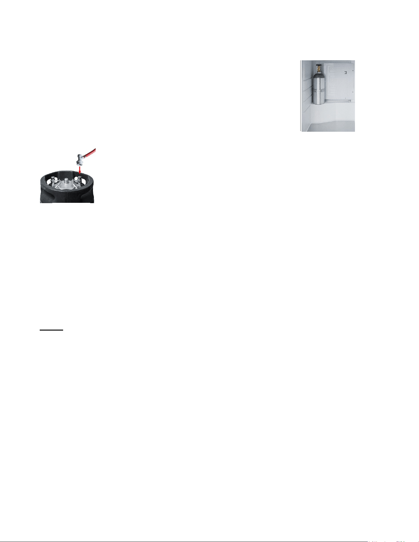
3. Install the beer keg:
Note: This unit can hold two one-sixth barrel kegs,
but not a full-size keg.
Place the beer keg into the cabinet and firmly connect
the keg’s opening to the connection port of the mixed
ball valve.
Note: To place a keg into the cabinet, use the keg handle to move the keg to the front of the
open beer
dispenser, then carefully tip the keg so that the raised bottom edge contacts the
edge of the cabinet.
Finally, lift the keg handle to raise the keg to the level of the floor of the
cabinet and push the keg into
place.
4.
Install tap handle and beer tap:
Screw the tap handle clockwise into the beer tap to make a firm connection. Then connect the tap to
the beer
tower components and tighten it with a wrench (See Figure 9).
Notes:
When replacing the beer keg, first turn off the safety switch on the CO
2
regulator valve and
remove the
mixed ball valve to take out the keg.
When replacing the CO
2
gas cylinder, remember to turn off the main switch of the CO
2
gas
cylinder and
the safety switch on the CO
2
regulator valve. Afterwards, use a wrench to loosen
the hexagonal nut port
connecting the CO
2
regulator valve with the CO
2
tank. Then, using a
wrench, remove the fixed bolt of the
CO
2
tank to take out the CO
2
tank.
During the installation process, be sure that all parts are connected tightly and that there are no
gas
leaks.
When connecting the hose to the connection port, you can dip the ends into warm water to make
the
connection easier.
If the high-pressure compressed gas in the CO
2
tank is not handled properly, it could be
dangerous:
o Make a note of the D.O.T. testing date on the cylinder neck before installation. If it is more
than 5 years old, don’t use the product. Return it to the gas supplier.
o Keep gas cylinder away from heat sources. Unused cylinders should be placed upright in a
cool, ventilated place (preferably at 70ᵒF).

15
Installation Instructions for Cold Brew Coffee Tap Kits
Flat Iced Coffee Kits: KitCF KitCFTWIN
Nitro-Infused Coffee Kits: KitNCF KitNCFTWIN
Combination Flat/Nitro Kit: KitCMTWIN
Parts & Equipment
(not included)
Installation
1. Put draft tower directly over the hole on the top of the coffee dispenser’s upper
surface. Fix the tower assembly with screws directly to the upper surface of the
dispenser. (See Fig. 1.)
3.
Using a wrench, tighten the hex nut port on the regulator valve to the N
2
gas
outlet on the N
2
gas cylinder. (See Fig. 2.)
Fig. 1
Fig. 2
16
3. Place the N
2
gas cylinder into the bracket on the rear wall of the
kegerator’s inside cabinet and fix the N
2
cylinder with the bolt. (See Fig. 3.;
note: some units do not include a bracket)
4. Carefully place the keg inside the kegerator. Attach the coffee tube from the
tower to the “out” post of the of the Cornelius keg by pushing the ball lock down
over the “out” post until it snaps in place. (See Fig 4.)
5. Attach the N
2
tube to the “in” post of the Cornelius keg by pushing the ball lock
down over the “in” post unit it snaps on.
6. Set the desired pressure on the regulator valve. If serving flat iced coffee, open the regulator valve
and set the pressure between 4-8 psi. If serving nitro-infused coffee, set the pressure between 30-
45 psi.
7. Install the tap handle(s) and coffee tap(s). Screw the tap handle clockwise into the coffee tap to
make a firm connection, then connect the tap to the coffee tower components and tighten with a
wrench.
NOTE: If serving nitro-infused coffee, agitate the keg before serving.
8. Install the upper cover guardrail (provided with your kegerator) and drip tray.
Notes:
These taps are designed for dispensing coffee and should not be used for milk or any other
substance.
When replacing the coffee keg, first turn the safety switch on the N
2
regulator valve and
remove the ball locks to take out the keg.
When replacing the N
2
gas cylinder, remember to turn off the main switch of the N
2
tank and
the safety switch on the N
2
regulator valve. Afterwards, use a wrench to loosen the hexagonal
nut port connecting the N
2
regulator valve with the N
2
tank. Then, using a wrench, remove the
fixed bolt of the N
2
tank.
During the installation process, be sure that all parts are connected tightly and that there are
no gas leaks.
High-pressured compressed gas in the N
2
tank can be dangerous if not handled properly. For
optimum safety, make a note of the D.O.T. testing date on the cylinder neck before installation.
If it is more than 5 years old, do not use.
Keep the gas cylinder away from heat sources. Unused cylinders should be placed upright in a
cool, ventilated place, preferably at 70°F.
Fig. 3
Fig. 4
17
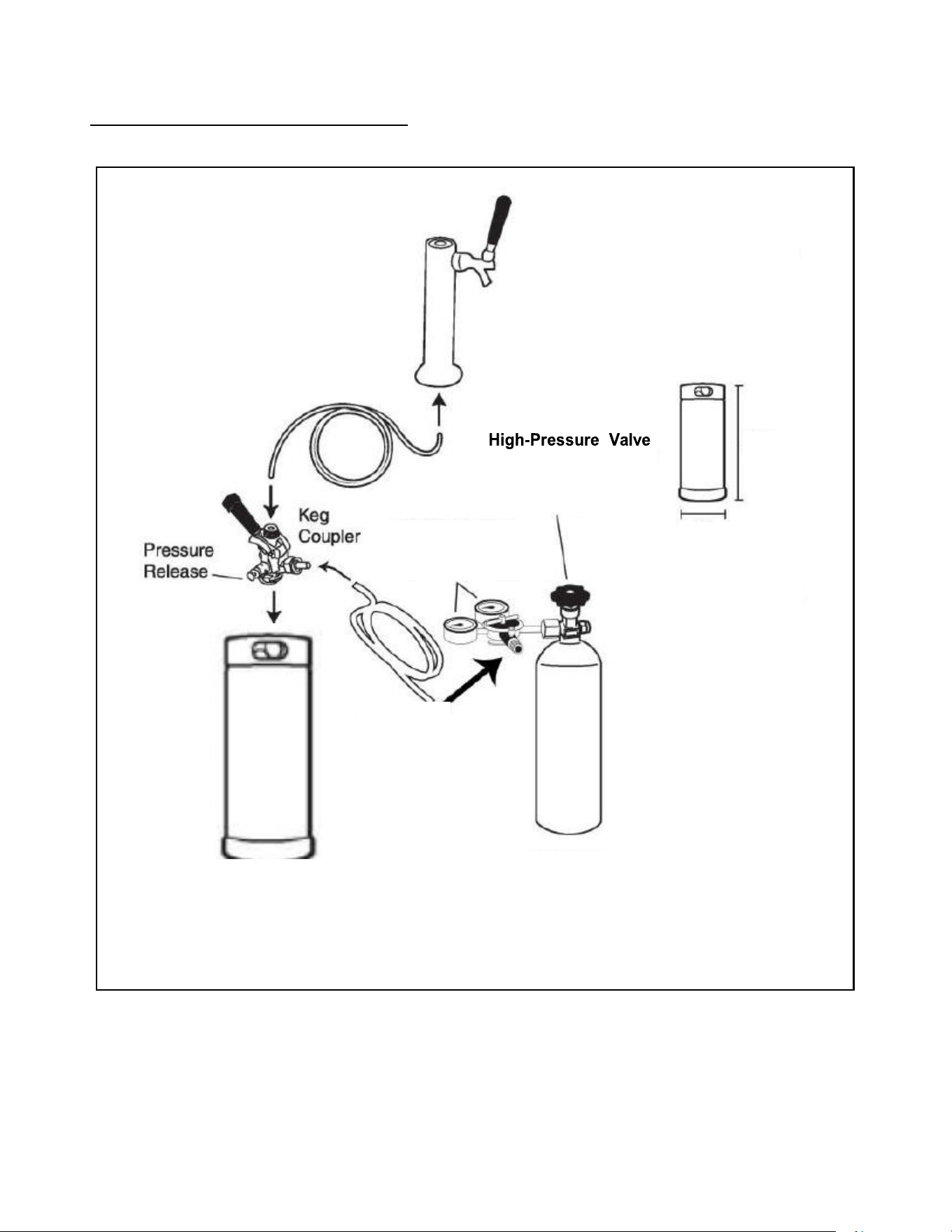
Wine Dispenser Tap Kit Instructions
WINE KEG DISPENSER FLOW AND PARTS
Wine Keg
Dimensions
Gas Canister
S
hut Off Safely
Double Gauge
Gas Regulator
Low Pressure Valve
Wine Line
(NSF-certified
Barrier Tubing)
Wine
Dispenser
Tower
Gas Line
23⅜”
9¼”
Gas Tank
1/6 Barrel Wine Keg
(Not Included)
18
Be sure you have a thorough familiarity with the
assembly and installation process before turning
on your wine keg dispenser.
NOTE: Once casters are assembled, place your
unit in an upright position and allow it to sit for at
least 8-10 hours before plugging into an outlet.
This will allow the refrigerant to settle before
operation.
Caster Assembly
1. Remove
everything
from the
cabinet and lay
the unit on a
clean, dry, and
padded surface.
2. Install casters
into holes on
the bottom of
the unit as
shown and
tighten with a wrench. Two of the four casters
provided are equipped with locks to prevent
slippage of the unit on smooth surfaces such
as hardwood floors, linoleum, or tile. These
casters should be installed on the front of
the unit.
3. Once all four casters are attached, return the
wine keg dispenser to an upright position and
allow to remain for at least 8-10 hours. (See
Note above.)
Guardrail Installation
To install the guardrail,
1. Place the guardrail on top of the wine keg
dispenser and line up the feet of the guardrail
with the holes on top of the cabinet.
2. Using the screws provided, secure each foot to
the cabinet.
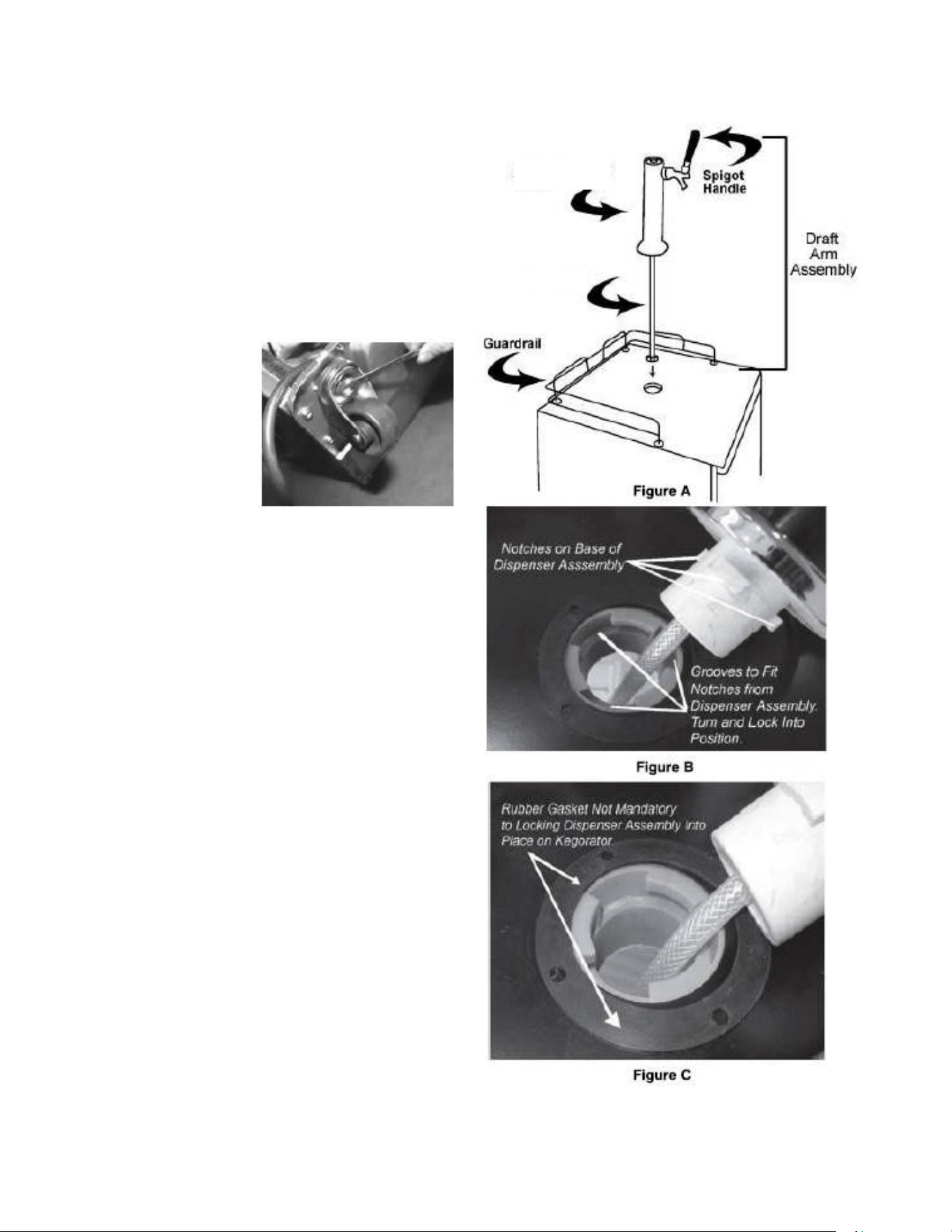
Wine Tap Installation
To install the wine tap, first line up the draft arm
notches with the notches in the hole in the top of
the wine keg dispenser. Feed the arm into the
hole, making sure that the notches are aligned
properly. Slide arm down and twist until the arm is
secure. (No screws or fasteners are necessary.)
While not required, we recommend the use of the
black rubber gasket when installing the wine tap.
Using the gasket will provide a more secure
seating for the arm assembly. (See figures A, B,
and C in the next column.)
Wine Duct
Wine Dispenser
Tower
19
Use a gas mixture consisting of 75% nitrogen (N
2
) and 25% carbon dioxide (CO
2
).
Gas Regulator Installation
Proper installation of your gas
regulator and a thorough
understanding of gas canisters are
essential to the safe use of this
product. Review and follow
instructions for handling gas cylinders
and this section to ensure your safety
and the safety of others.
NEVER CONNECT A GAS
CANISTER DIRECTLY TO THE
UNIT
! To avoid a potential explosion
that could result in grave injury or
even death, ALWAYS CONNECT THE
CANISTER TO THE GAS REGULATOR.
IMPORTANT! The gas canister is shipped to you EMPTY for safety reasons. You will need to get this
canister filled before you can use your unit. In most areas, you can get canisters filled at:
stores that sell kegs
party stores or convenience stores
fire and welding supply stores.
DO NOT ATTEMPT TO REFILL GAS CANISTERS YOURSELF!
DANGER! Any pressurized gas is potentially dangerous. Canisters or cylinders are under
pressure and proper handling is essential to safety. ALWAYS HANDLE WITH CARE!
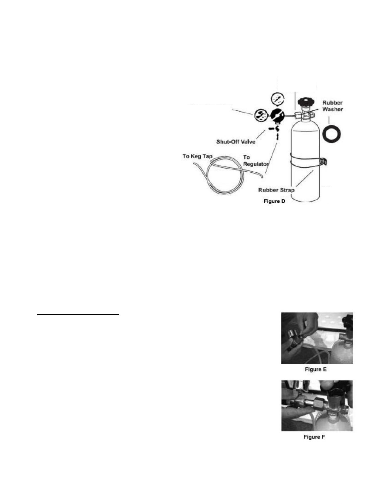
To install the NO2 canister:
1. I Insert the end of the gas line with the green coupler onto the
bottom end of the regulator. (See Figure D and Photo 1). Secure
the line to the regulator by tightening the green coupler. Secure
the gas line by tightening the green coupler.
2. Next, insert the black rubber washer into the attachment nut into
the regulator and connect the regulator to the gas canister
valve. Tighten with an adjustable wrench (not provided). DO
NOT OVERTIGHTEN. (As shown in figure E)
3. Attach the NO2 gas line to the regulator outlet nipple and
secure it with a clamp.
4. Secure the canister with the rubber restraining strap (on the side
of the wine keg dispenser cabinet) as shown in Figure D. Be
sure to situate the canister so that the gauges are easily
readable and shut-off valves are easily accessible.
SPECIAL PRECAUTIONS: Ensure that the safety devices for your pressurized system are installed and remain
installed. Once installed, NEVER remove the rubber washers in the regulator attachment nut to the canister or in
the tap mechanism. NEVER bypass these safety features.
Connect to
Gas Cylinder
25% CO
2
Gas
Cylinder
Gas Line
75% N
2
Gas Regulator
20
FAILURE TO COMPLY WILL VOID YOUR WARRANTY AND COULD RESULT IN
SERIOUS INJURY OR DEATH
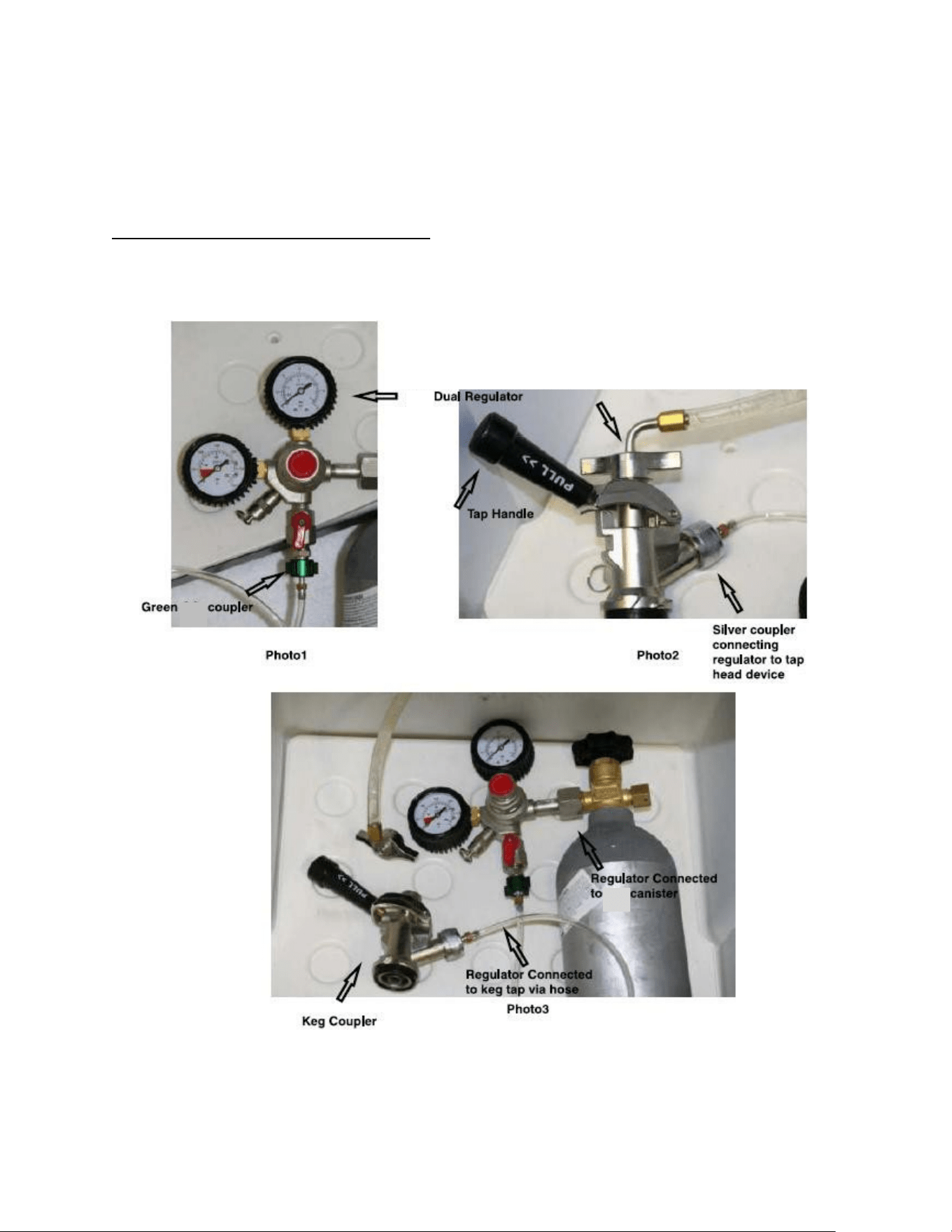
Gas R
egulator & Tap Connection Examples
PLEASE NOTE: Your gas hose comes equipped and assembled with coupling connections for the
regulator (green coupler) and the tap connection (silver coupler). The photos below show correct
connections.
Gas
gas
gas
Wing Nut Connecting Wine Hose to Tap
21
Installing Keg Tap on Single Barrel Type Keg
This wine dispenser's coupler is compatible only with a single 1/6 barrel keg, although a second untapped
keg can be stored behind the tapped keg to keep it cold. Each 1/6 barrel keg holds approximately 5
gallons of wine.
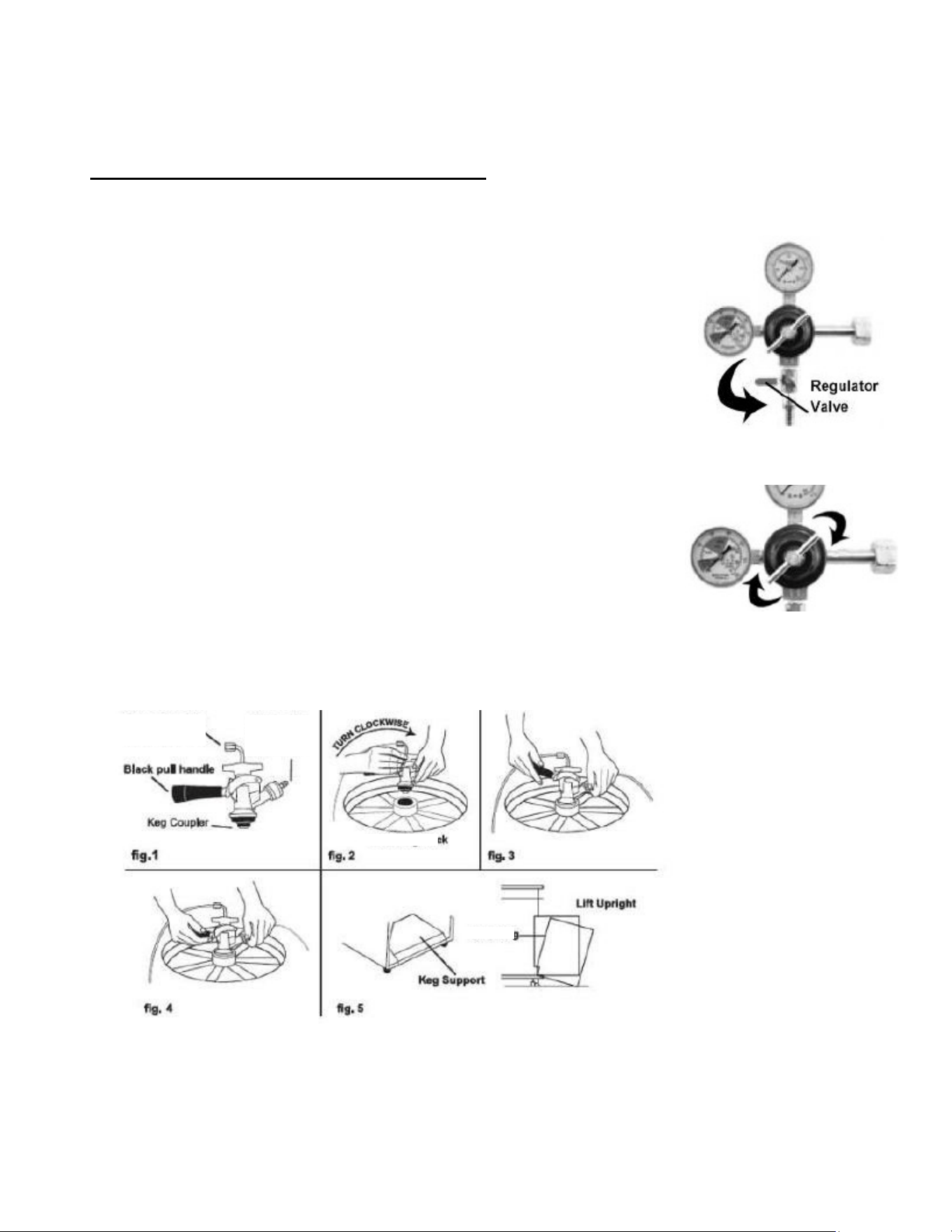
To tap a keg:
1. First be sure that the black dispenser handle is pushed up, indicating an
untapped keg (See Fig.1 below). Also, make sure the tower dispenser (on top of
the wine dispenser) is closed before starting the tap-to-keg connection.
2. Connect the other end of the NO2 pressure tubing to the NO2 pressure inlet
nipple on the keg coupler and secure it with a clamp. Insert the keg coupler
mechanism into the top of the keg and lock it into the lugs with a one-quarter
clockwise turn (Fig.2 & Fig.3).
3. Open the NO2 cylinder valve by turning the knob counterclockwise, open it all
the way to be sure there are no leaks. Then, set the pressure between 5-7 psi, this accommodates most
wine kegs. After the pressure is set, tighten the locknut to prevent tampering with the setting.
4. Connect the wine line wingnut to the keg coupler and tighten it.
5. Turn the shut-off lever down to allow the gas to flow.
6. To finalize the connection, pull the black tap handle out and push it down until it
clicks securely. There will be an audible click, indicating that the gas and wine
have been opened and your keg is tapped. (Fig.4)
7. Open the regulator valve (top right photo) and open the valve on the gas tank.
8. Carefully, tilt the keg onto the cabinet (using the keg support shown in Fig. 5)
and position slowly into the cabinet body until the door can close. HANDLE CAREFULLY. Do not jostle
or bang the keg on the gas canister.
Note: The left regulator gauge indicates the total tank pressure
Wine Keg Neck
Wine Keg
Connect to
Gas Line
Tube
Connect to the
Wine Line Tube
22
Operating Your Kegerator
Temperature Control:
Your appliance’s evaporator system is out of sight behind the interior rear wall.
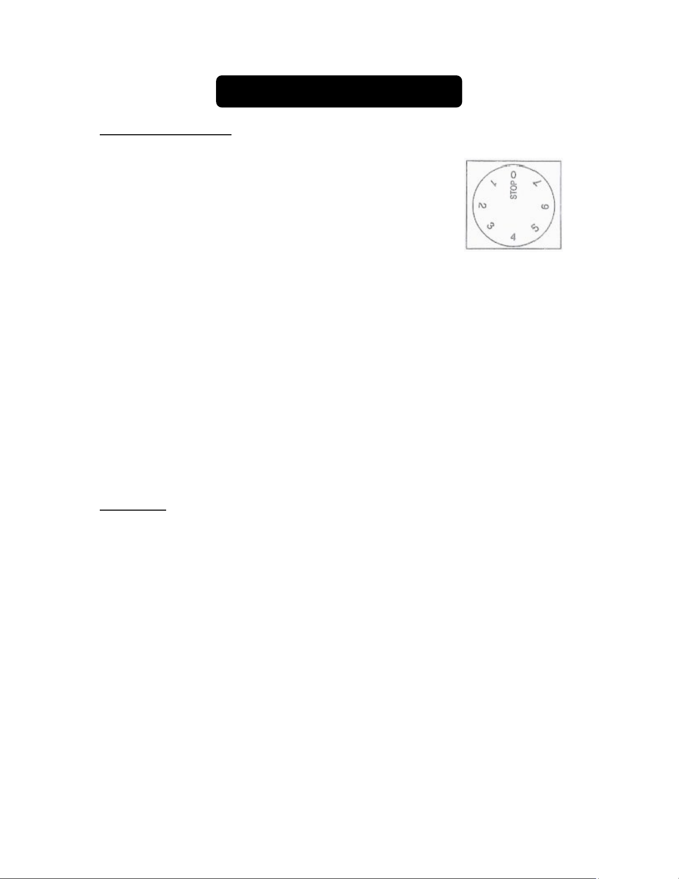
The interior temperature is controlled with a thermostat knob
located inside the unit, towards the upper right-hand corner.
Turn the knob clockwise from the STOP (0) position toward
the higher numbers for colder temperatures. Higher settings
on the knob (higher numbers) mean lower temperatures
(colder) in the kegerator.
On the coldest settings, temperatures in some spots inside
the cabinet may drop below 32°F. Use higher thermostat settings only when required
or recommended. When the ambient temperature is normal, we recommend a
medium setting.
Changes in the ambient temperature affect the temperature inside the refrigerator so
choose an appropriate setting of the thermostat knob, depending on ambient
conditions.
In the STOP (0) position, the appliance does not operate (the cooling system is
switched off), yet the power supply is not interrupted (the light still works).
The temperature inside the kegerator also depends on how often you open the door.
NOTES:
1. Interior lighting is controlled by a manually operated rocker switch. To maintain the
proper interior temperature, keep the light on only as long as necessary.
2. If the kegerator is unplugged, has lost power, or is turned off, you must wait 3 to 5
minutes before restarting it. If you attempt to restart before this time delay, the unit will
not start.
Defrosting:
This appliance operates with an automatic defrost system, so it defrosts itself. While the
compressor is operating, ice will build along the rear cold wall (the evaporator plate is
behind the wall). During the compressor’s off-cycle, ice will melt, drip down, collect in the
trough at the bottom, and drain through a small hole into a tray above the compressor;
where the compressor’s heat will evaporate the water. If you notice excessive ice build-
up on the rear wall, try setting the thermostat to a slightly warmer setting; be sure that
the door gasket is sealing well and that there is no obstruction of the drain hole at the
bottom rear of the interior cabinet.
23
Care and Maintenance
Cleaning Your Appliance:
1. Unplug the appliance, turn the thermostat to STOP (0), and remove all contents,
including shelves.
2. Wash the inside surfaces with a solution of lukewarm water and vinegar. Wipe dry
with a clean, soft cloth.
3. Wash the outside cabinet with a solution of warm water and mild liquid detergent.
Rinse well and wipe dry with a clean, soft cloth.
4. Wring excess water out of the sponge or cloth before cleaning the area of the
temperature control or any electrical parts.
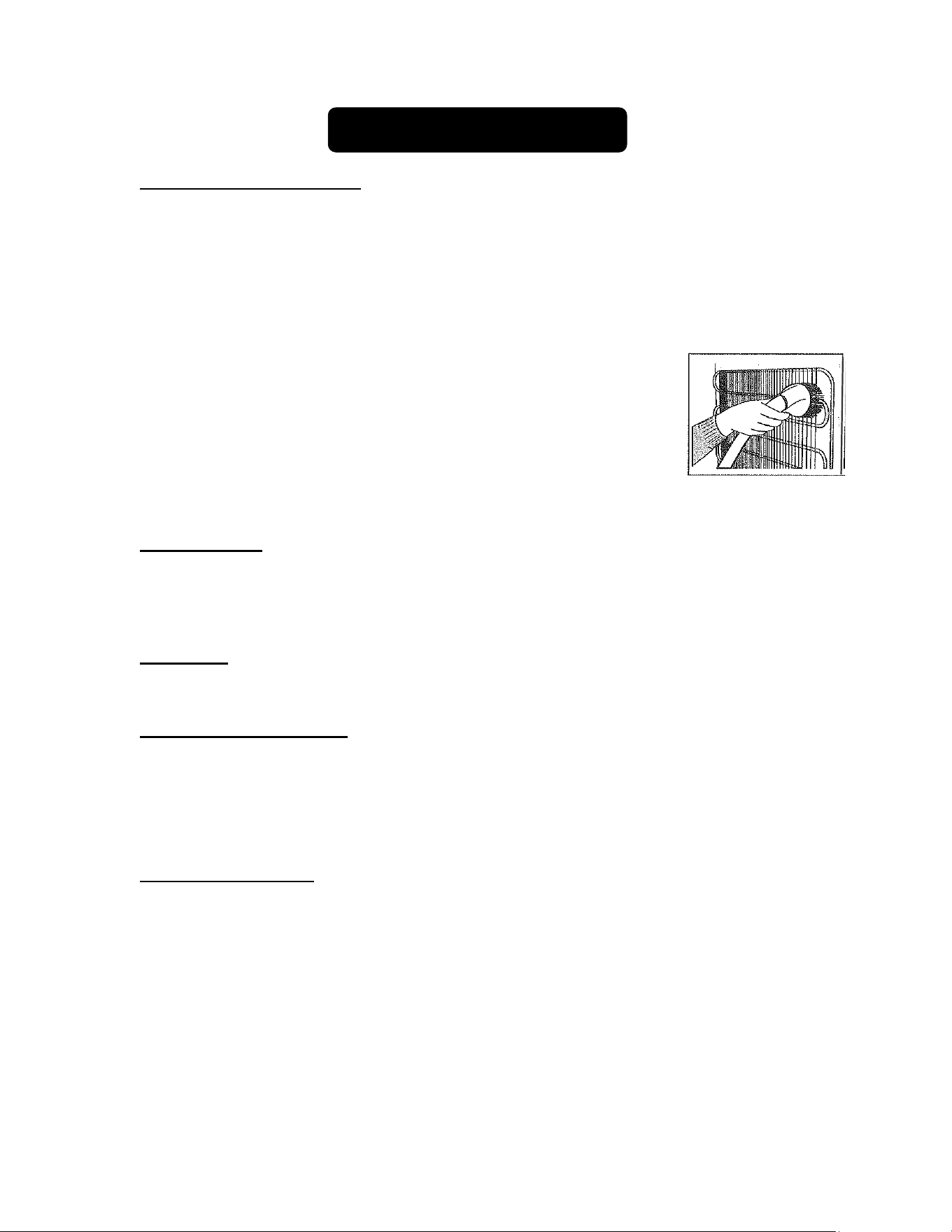
5. From time to time, wipe the condenser on the rear wall with a soft
non-metallic brush or vacuum cleaner.
6. After you have cleaned the appliance, reconnect it to the power
supply, reset the thermostat and return all contents to their place.
CAUTION: Failure to unplug the unit could result in electrical shock or personal injury.
Power Failure:
Most power failures are corrected within a few hours and should not affect the
temperature of your appliance if you minimize the number of times the door is opened. If
the power is going to be off for a longer period of time, you need to take the proper steps
to protect your chilled items.
Vacations:
During long absences, remove all contents. Unplug the appliance, clean it and leave the
door open slightly to avoid possible formation of condensation, mold or odors.
Moving Your Appliance:
1. Remove the contents.
2. Securely tape down anything loose inside your unit.
3. Turn the leveling legs up to the base to avoid damage.
4. Tape the door shut.
5. Be sure the appliance stays secure in the upright position during transportation.
Energy-Saving Tips:
The unit should be located in the coolest area of the room, away from heat-producing
appliances or heating ducts and out of direct sunlight.
Try not to open the door too often, especially when the weather is damp and hot.
Once you open the door, close it as soon as possible.
Occasionally check if the appliance is sufficiently ventilated (adequate air circulation
behind the appliance).
Set the thermostat from higher to lower settings as soon as possible (depending on
how loaded the appliance is, ambient temperature, etc.).
Before loading items into the unit, be sure they have cooled to ambient temperature.
24
Draft Troubleshooting
Problem
Cause
Correction
Beer is cloudy: The
beer in the
glass
appears hazy and
not clear.
Excessively low
temperatures
may
cause hazy
or
cloudy beer,
particularly when
the beer lies in
the
cold coil for
long
periods of
time.
Drain a few ounces before drinking.
Raise the temperature setting of the unit.
Glasses may not
have been
cleaned
properly.
Do not wash beer glasses together with glasses that
have
contained milk or any other fatty substance. An
excessive
amount of germicide build-up may also
leave a fatty film,
which will cause beer to go flat.
It is preferable to steam and sterilize glasses where
health laws permit.
Wash glasses thoroughly with a good detergent to
remove all fatty substances (e.g., lipstick).
Do not use soap.
Do not wipe the glasses dry. Permit glasses to air-dry
by
placing them on a wire rack or corrugated metal
sheet.
Rinse the glasses in fresh cold water just before
serving
beer. It is best to serve beer in a wet glass.
Improper drawing
of beer into glass
Open the faucet quickly and completely; proper foam
should be a tight creamy head. The collar on the
average
glass should be ¾" to 1" high. Beer drawn
without a head
has the appearance of being flat.
Not enough
pressure
Increase the pressure if beer runs too slowly. The
correct
flow should fill a 10-oz glass in 4 seconds
(approx. 8 oz of
liquid). Check the pressure source to
determine whether
there are obstructions in the air
line. Replace a sluggish air
source or the CO
2
regulator and gauge. The tank pressure
must always
be higher than the pressure used on the keg.
Always
apply pressure to the keg before drawing beer.
Beer has off taste:
Often bitter and
bite-y; sometimes
completely
lacking
flavor and zest. It
may also
have an
oily or foul odor
which may
carry an
unpleasant taste.
Improper
cleaning of the
tap
Brush and clean the tap properly. It should be
scoured using a detergent, then rinsed clean.
Contaminated air
line
Beer tube should be examined. If contaminated, it
should be replaced.
25
Condensation is
forming on the
tap.
It is normal to see
condensation
forming on the
tap.
It is caused
by a
difference in
temperature
between the cold
beer and the
surfaces of the
tap
when beer is
flowing through
the
line. Beer that
is left
in the tap is
not
cooled by the
beer
dispenser.
After a period of non-use, a few ounces should be
drained before drinking.
If you have checked the table above and find that you still need help with your kegerator, call our
Customer Service facility at 800-932-4267 between 9:00 AM and 5:00 PM ET or
visit www.summitappliance.com/support
. We will do our best to answer your questions.

26
General Troubleshooting
When using this appliance, you may come across some problems that in many cases
result from improper handling and can easily be eliminated.
TROUBLESHOOTING GUIDE
The appliance fails to operate after being connected to the power source.
Check whether the power supply is active and that the thermostat is not set to the
STOP (0) position.
The compressor is running continuously.
The door was opened frequently or it was left open too long.
The door is not properly closed (the door may sag, the gasket may be dirty or
damaged).
The power supply has been interrupted for a long period of time.
The appliance may have been overloaded with items above room temperature.
There may be inadequate ventilation of the compressor and condenser. (Assure
there is adequate air circulation behind the appliance and wipe the dust from the
condenser.)
Noise
Cooling in refrigeration appliances is enabled by the refrigerating system with a
compressor, which produces noise. How noisy the appliance is depends on where
it is placed, how it is used and how old the appliance is.
During the operation of the compressor, the noise of liquid is heard and when the
compressor is not operating, the refrigerant flow is heard. This is a normal
condition and has no influence whatsoever on the lifetime of the appliance.
After starting the appliance, the operation of the compressor and the refrigerant
flow may be louder. This does not mean that something is wrong. Gradually the
noise is reduced.
Sometimes a louder noise is heard, which is unusual for the appliance. This noise
is often a consequence of improper placement of the unit. (The unit should be
placed and leveled firmly on a solid base and it should not touch the wall or
cabinets standing next to it.)

27
Notes
28
December 2023
Printed in the U.S.A.
Limited Warranty
ONE-YEAR LIMITED WARRANTY
Within the 48 contiguous United States, for one year from the date of purchase, when this appliance is
operated and maintained according to instructions attached to or furnished with the product, warrantor will
pay for factory-specified parts and repair labor to correct defects in materials or workmanship. Service
must be provided by a designated service company. Outside the 48 states, all parts are warranted for one
year from manufacturing defects. Plastic parts, shelves and cabinets are warranted to be manufactured to
commercially acceptable standards, and are not covered from damage during handling or breakage.
5-YEAR COMPRESSOR WARRANTY
1. The compressor is covered for 5 years.
2. Replacement does not include labor.
ITEMS WARRANTOR WILL NOT PAY FOR:
1. Service calls to correct the installation of your appliance, to instruct you how to use your appliance,
to replace or repair fuses or to correct wiring or plumbing.
2. Service calls to repair or replace appliance light bulbs or broken shelves. Consumable parts (such
as filters) are excluded from warranty coverage.
3. Damage resulting from accident, alteration, misuse, abuse, fire, flood, acts of God, improper
installation, installation not in accordance with electrical or plumbing codes, or use of products not
approved by warrantor.
4. Replacement parts or repair labor costs for units operated outside the United States.
5. Repairs to parts or systems resulting from unauthorized modifications made to the appliance.
6. The removal and reinstallation of your appliance if it is installed in an inaccessible location or is not
installed in accordance with published installation instructions.
DISCLAIMER OF IMPLIED WARRANTIES – LIMITATION OF REMEDIES
CUSTOMER'S SOLE AND EXCLUSIVE REMEDY UNDER THIS LIMITED WARRANTY SHALL BE
PRODUCT REPAIR AS PROVIDED HEREIN. IMPLIED WARRANTIES, INCLUDING WARRANTIES OF
MERCHANTABILITY OR FITNESS FOR A PARTICULAR PURPOSE, ARE LIMITED TO ONE YEAR.
WARRANTOR SHALL NOT BE LIABLE FOR INCIDENTAL OR CONSEQUENTIAL DAMAGES. SOME
STATES DO NOT ALLOW THE EXCLUSION OR LIMITATION OF INCIDENTAL OR CONSEQUENTIAL
DAMAGES, OR LIMITATIONS ON THE DURATION OF IMPLIED WARRANTIES OF
MERCHANTABILITY OR FITNESS, SO THESE EXCLUSIONS OR LIMITATIONS MAY NOT APPLY TO
YOU. THIS WARRANTY GIVES YOU SPECIFIC LEGAL RIGHTS AND YOU MAY ALSO HAVE OTHER
RIGHTS, WHICH VARY FROM STATE TO STATE.
For parts and accessory ordering,
troubleshooting and helpful hints, visit:
www.summitappliance.com/support
FELIX STORCH, INC.
770 Garrison Avenue
Bronx, NY 10474
Phone:
(718) 893-3900
Fax: (
844) 478-8799
www.
summitappliance.com