
OTRO_ BILT
OPERATOR'S MANUAL
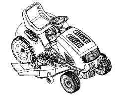
Pedal Drive Garden Tractor
Model 809
Mode1148va09H063 Shown
IMPORTANT: READ SAFETY RULES AND INSTRUCTIONS CAREFULLY
Warning: This unit is equipped with an internal combustion engine and should not be used on or near any unimproved forest-cov-
ered, brush-covered or grass-covered land unless the engine's exhaust system is equipped with a spark attester meeting applicable
local or state laws (if any). If a spark arrester is used, it should be maintained in effective working order by the operator. In the State of
California the above is required by law (Section 4442 of the California Public Resources Code). Other states may have similar laws.
Federal laws apply on federal lands. A spark arrester for the muffler is available through your nearest engine authorized service dealer
or contact the service department, P.O. Box 368022 Cleveland, Ohio 44136-9722.
MTD PRODUCTS INC. P.O. BOX 368022 CLEVELAND, OHIO 44136-9722
PRINTED IN U.S.A. FORM NO. 770-10189A
(10/99)
SECTION 1: TABLE OF CONTENTS
PAGE
FINDING YOUR MODEL NUMBER ....................................................... 2
CALLING CUSTOMER SUPPORT ........................................................ 2
IMPORTANT SAFE OPERATION PRACTICES.............................................. 3
SAFETY LABLES FOUND ON YOUR UNIT................................................. 5
SLOPE GUAGE ...................................................................... 6
ATTACHMENTS & ACCESSORIES ....................................................... 7
TRACTOR SET-UP.................................................................... 7
CONTROLS ......................................................................... 9
OPERATION ........................................................................ 12
ADJUSTMENTS ..................................................................... 15
MAINTENANCE ..................................................................... 18
LUBRICATION ...................................................................... 25
TROUBLESHOOTING CHART.......................................................... 26
PARTS LIST ........................................................................ 28
WARRANY INFORMATION ..................................................... Back Cover
SECTION 2: FINDING YOUR MODEL NUMBER
This Operator's Manual isan important part of your new rider. It will help you assemble, prepare and maintain
your rider. Please read and understand what it says.
Before you start to prepare your tractor for its first use, please locate the model plate and copy the information
from it in this Operator's Manual. The information on the model plate is very important if you need help from
your dealer or the MTD Customer Support Department.
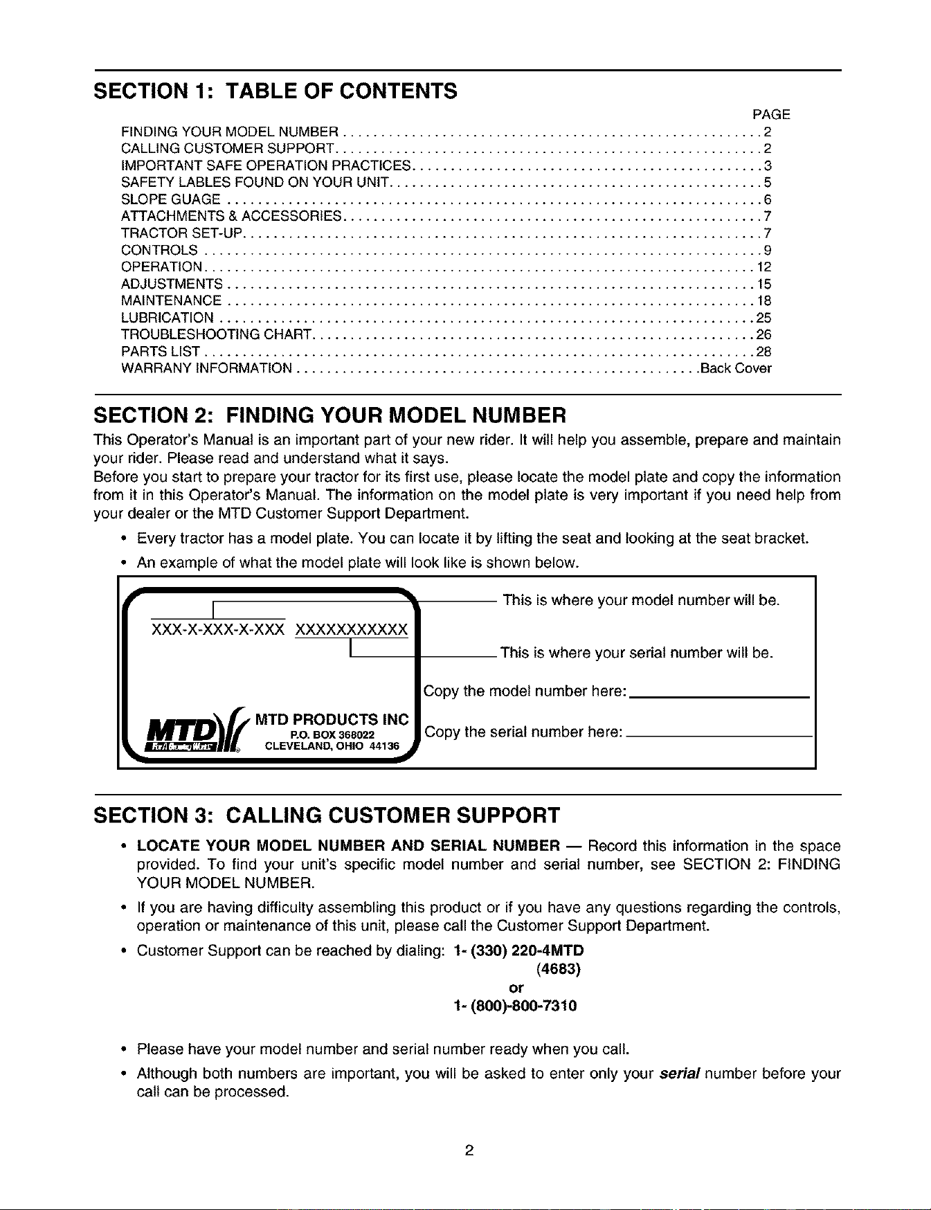
• Every tractor has a model plate. You can locate it by lifting the seat and looking at the seat bracket.
• An example of what the model plate will look like is shown below.
I
XXX-X-XXX-X-XXX XXXXXXXXXXX
I IJRI_'I'_E MTD PRODUCTS INC
• _=IIV |H H P.O. BOX 368022
__H_J_ CLEVELAND, OHIO 44136
This is where your model number will be.
This is where your serial number wilt be.
Copy the model number here:
Copy the serial number here:
SECTION 3: CALLING CUSTOMER SUPPORT
• LOCATE YOUR MODEL NUMBER AND SERIAL NUMBER -- Record this information in the space
provided. To find your unit's specific model number and serial number, see SECTION 2: FINDING
YOUR MODEL NUMBER.
• If you are having difficulty assembling this product or if you have any questions regarding the controls,
operation or maintenance of this unit, please call the Customer Support Department.
• Customer Support can be reached by dialing: 1- (330) 220-4MTD
(4683)
or
1- (800)-800-7310
• Please have your model number and serial number ready when you call.
• Although both numbers are important, you will be asked to enter only your serial number before your
call can be processed.
SECTION 4: IMPORTANT SAFE OPERATION PRACTICES
WARNING: THIS SYMBOL POINTS OUT IMPORTANT SAFETY INSTRUCTIONS WHICH, IF
NOT FOLLOWED, COULD ENDANGER THE PERSONAL SAFETY AND/OR PROPERTY OF
YOURSELF AND OTHERS. READ AND FOLLOW ALL INSTRUCTIONS IN THIS MANUAL
BEFORE ATTEMPTING TO OPERATE YOUR LAWN MOWER. FAILURE TO COMPLY WITH
THESE INSTRUCTIONS MAY RESULT IN PERSONAL INJURY. WHEN YOU SEE THIS SYMBOL,
HEED ITS WARNING.
WARNING: The Engine Exhaust from this product contains chemicals known to
the State of California to cause cancer, birth defects or other reproductive harm.
DANGER: Your lawn mower was built to be operated according to the rules for safe operation in
this manual. As with any type of power equipment, carelessness or error on the part of the operator
can result in serious injury. This lawn mower is capable of amputating hands and feet and throwing
objects. Failure to observe the following safety instructions could result in serious injury or death.
1. GENERAL OPERATION
• Read, understand, and follow all instructions in the
operator's manual and on the machine before
starting. Keep this manual in a safe place for future
and regular reference and for ordering replacement
parts.
• Only allow responsible individuals familiar with the
instructions to operate the machine. Know controls
and how to stop the machine quickly.
• Do not put hands or feet under cutting deck or near
rotating parts.
• Clear the area of objects such as rocks, toys, wire,
etc., which could be picked up and thrown by the
blade. A small object may have been overlooked
and could be accidentally thrown by the mower in
any direction and cause injury to you or a
bystander. To help avoid a thrown objects injury,
keep children, bystanders and helpers at least 75
feet from the mower while it is in operation. Always
wear safety glasses or safety goggles during
operation or while performing an adjustment or
repair, to protect eyes from foreign objects. Stop
the blade(s) when crossing gravel drives, walks or
roads.
• Be sure the area is clear of other people before
mowing. Stop machine if anyone enters the area.
• Never carry passengers.
• Disengage blade(s) before shifting into reverse and
backing up. Always look down and behind before
and while backing.
• Be aware of the mower and attachment discharge
direction and do not point it at anyone. Do not
operate the mower without either the entire grass
catcher or the chute guard in place.
• Slow down before turning. Operate the machine
smoothly. Avoid erratic operation and excessive
speed.
• Never leave a running machine unattended. Always
turn off blade(s), place transmission in neutral, set
park brake, stop engine and remove key before
dismounting.
•Tum off blade(s) when not mowing.
• Stop engine and wait until blade(s) comes to a
complete stop before (a) removing grass catcher or
unclogging chute, or (b) making any repairs,
adjusting or removing any grass or debris.
• Mow only in daylight or good artificial light.
• Do not operate the machine while under the
influence of alcohol or drugs.
• Watch for traffic when operating near or crossing
roadways.
• Use extra care when loading or unloading the
machine into a trailer or truck. This unit should not
be driven up or down a ramp onto a trailer or truck
under power, because the unit could tip over,
causing serious personal injury. The unit must be
pushed manually on a ramp to load or unload
properly.
• Never make a cutting height adjustment while
engine is running if operator must dismount to do
SO.
• Wear sturdy, rough-soled work shoes and close-
fitting slacks and shirts. Do not wear loose fitting
clothes or jewelry. They can be caught in moving
parts. Never operate a unit in bare feet, sandals, or
sneakers.
• Check overhead clearance carefully before driving
under power lines, wires, bridges or low hanging
tree branches, before entering or leaving buildings,
or in any other situation where the operator may be
struck or pulled from the unit, which could result in
serious injury.
• Disengageall attachmentclutches,thoroughly
depressthe brakepedal,andshiftintoneutral
beforeattemptingtostartengine.
• Yourmowerisdesignedtocutnormalresidential
grassofaheightnomorethan10".Donotattempt
to mowthroughunusuallytall,dry grass(e.g.,
pasture)orpilesofdryleaves.Debrismaybuildup
onthemowerdeckorcontacttheengineexhaust
presentingapotentialfirehazard.
2. SLOPE OPERATION
Slopes are a major factor related to loss of control and tip-
over accidents which can result in severe injury or death.
All slopes require extra caution. If you cannot back up the
slope or if you feel uneasy on it, do not mow it.
For your safety, use the slope gauge included as part of
this manual to measure slopes before operating this unit on
a sloped or hilly area. If the slope is greater than 15 ° as
shown on the slope gauge, do not operate this unit on that
area or serious injury could result.
DO:
• Mow up and down slopes, not across.
• Remove obstacles such as rocks, limbs, etc.
• Watch for holes, ruts or bumps. Uneven terrain
could overturn the machine. Tall grass can hide
obstacles.
• Use slow speed. Always keep machine in gear
when going down slopes to take advantage of
engine braking action.
• Follow the manufacturer's recommendations for
wheel weights or counterweights to improve
stability.
• Use extra care with grass catchers or other
attachments. These can change the stability of the
machine.
• Keep all movement on the slopes slow and
gradual. Do not make sudden changes in speed or
direction. Rapid engagement or braking could
cause the front of the machine to lift and rapidly flip
over backwards which could cause serious injury.
• Avoid starting or stopping on a slope. If tires lose
traction, disengage the blade(s) and proceed slowly
straight down the slope.
DO NOT:
• Do not turn on slopes unless necessary; then, turn
slowly and gradually downhill, if possible.
• Do not mow near drop-offs, ditches or
embankments. The mower could suddenly turn
over if a wheel is over the edge of a cliff or ditch, or
if an edge caves in.
• Do not mow on wet grass. Reduced traction could
cause sliding.
• Do not try to stabilize the machine by putting your
foot on the ground.
• Do not use grass catcher on steep slopes.
3. CHILDREN
Tragic accidents can occur if the operator is not alert to the
presence of children. Children are often attracted to the
machine and the mowing activity. Never assume that chil-
dren will remain where you last saw them.
• Keep children out of the mowing area and in
watchful care of an adult other than the operator.
• Be alert and turn machine off if children enter the
area.
• Before and when backing, look behind and down
for small children.
• Never carry children, even with the blades off. They
may fall off and be seriously injured or interfere with
the safe machine operation.
Never allow children under 14 years old to operate
the machine. Children 14 years and over should
only operate machine under close parental
supervision and proper instruction.
• Remove key when machine is unattended to
prevent unauthorized operation.
• Use extra care when approaching blind corners,
shrubs, trees or other objects that may obscure
your vision of a child or other hazard.
4. SERVICE
Use extreme care in handling gasoline and other
fuels. They are extremely flammable and the
vapors are explosive.
Use only an approved container.
Never remove fuel cap or add fuel with the engine
running. Allow engine to cool at least two minutes
before refueling.
Replace fuel cap securely and wipe off any spilled
fuel before starting the engine as it may cause a
fire or explosion.
Extinguish all cigarettes, cigars, pipes and other
sources of ignition.
Never refuel the machine indoors because fuel
vapors will accumulate in the area.
Never store the fuel container or machine inside
where there is an open flame or spark, such as a
gas hot water heater, space heater or furnace.
Never run a machine inside a closed area.
To reduce fire hazard, keep the machine free of
grass, leaves or other debris build-up. Clean up oil
or fuel spillage. Allow machine to cool at least 5
minutes before storing.
Before cleaning, repairing or inspecting, make
certain the blade and all moving parts have
stopped. Disconnect the spark plug wire, and keep
the wire away from the spark plug to prevent
accidental starting.
Check the blade and engine mounting bolts at
frequent intervals for proper tightness. Also,
visually inspect blade for damage (e.g., excessive
wear, bent, cracked). Replace with blade which
meets odgina] equipment specifications.
• Keepallnuts,boltsandscrewstightto besurethe
equipmentisinsafeworkingcondition.
• Nevertamperwithsafetydevices.Checktheir
properoperationregularly.Useall guardsas
instructedinthismanual.
• Afterstrikinga foreignobject,stopthe engine,
removethewirefromthesparkplugandthoroughly
inspectthe mowerfor anydamage.Repairthe
damagebeforerestartingandoperatingthemower.
• Grasscatchercomponentsaresubjectto wear,
damageanddeterioration,whichcouldexpose
movingpartsor allowobjectsto bethrown.For
your safety protection,frequentlycheck
componentsand replacewith manufacturer's
recommendedpartswhennecessary.
• Mowerbladesaresharpandcancut.Wrapthe
blade(s)or wearglovesanduse extracaution
whenservicingblade(s).
• Checkbrakeoperationfrequently.Adjustand
serviceasrequired.
• Muffler,engineandbeltguardsbecomehotduring
operationandcancausea bum.Allowto cool
downbeforetouching.
Donotchangethe enginegovernorsettingsor
overspeedtheengine.Excessiveenginespeeds
aredangerous.
Observeproperdisposallawsand regulations.
Improperdisposaloffluidsandmaterialscanharm
theenvironmentandtheecology.
Priorto disposal,determinethepropermethodto
disposeof wastefromyourlocalEnvironmental
ProtectionAgency. Recyclingcenters are
establishedto properlydisposeof materialsin an
environmentallysafefashion.
Usepropercontainerswhendrainingfluids.Donot
usefoodorbeveragecontainersthatmaymislead
someoneintodrinkingfromthem.Properlydispose
ofthecontainersimmediatelyfollowingthedraining
offluids.
DONOTpouroilor otherfluidsintotheground,
downadrainorintoastream,pond,lakeorother
bodyofwater.ObserveEnvironmentalProtection
Agencyregulationswhendisposingof oil,fuel,
coolant,brakefluid,filters,batteries,tiresandother
harmfulwaste.
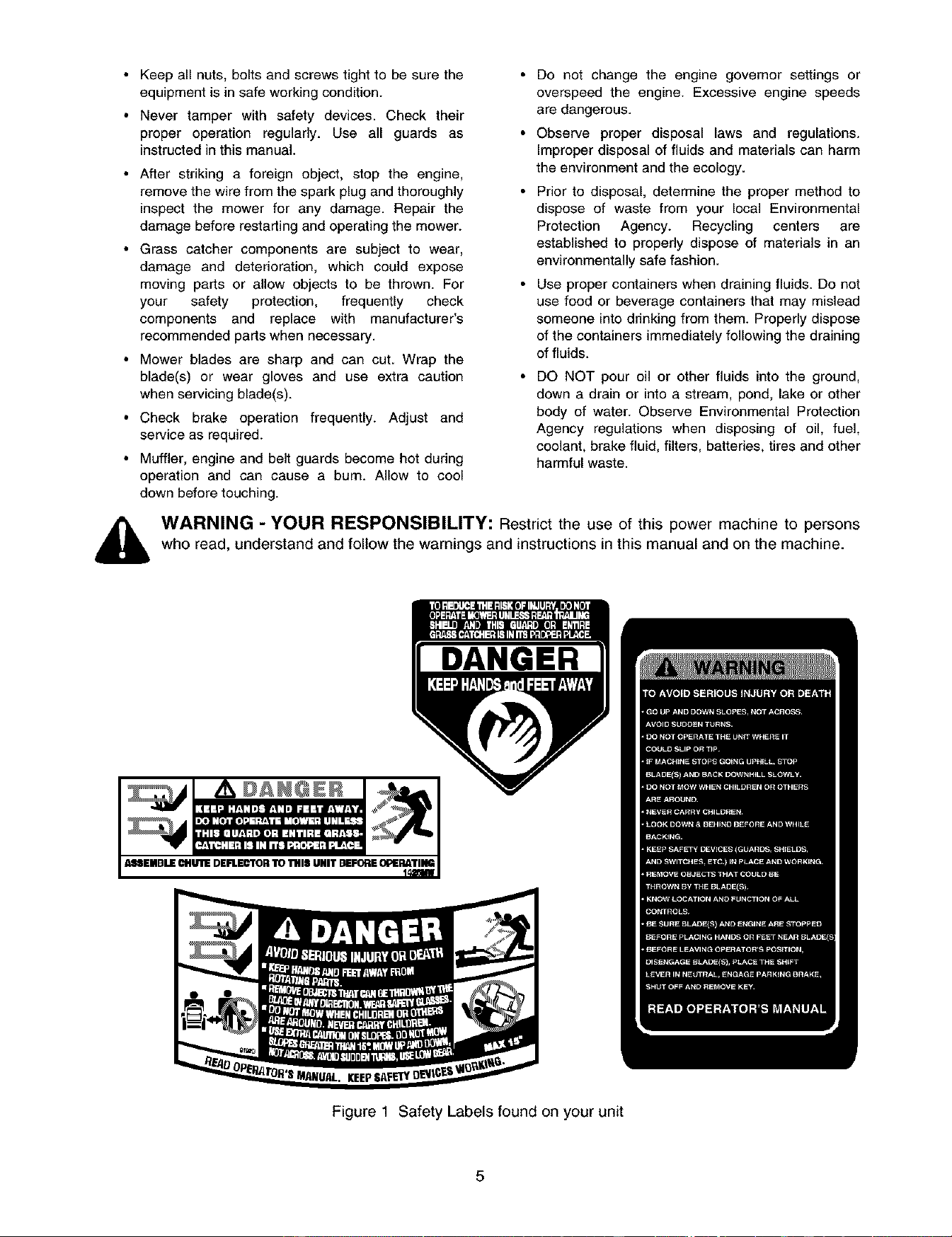
,_ WARNING - YOUR RESPONSIBILITY: Restrict the use of this power machine to persons
who read, understand and follow the warnings and instructions in this manual and on the machine.
DANGER
A,_SEMDLECHUT1EDEFLECTORTO 114111UNIT DEFOflE OPERATING
Figure 1 Safety Labels found on your unit
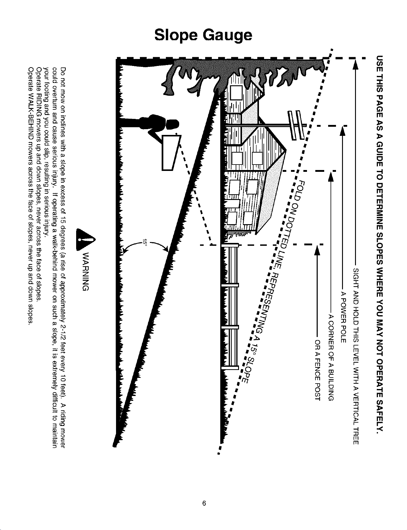
USE THIS PAGE AS A GUIDE TO DETERMINE SLOPES WHERE YOU MAY NOT OPERATE SAFELY.
O
SIGHT AND HOLD THIS LEVEL WITH A VERTICAL TREE
,91 A POWER POLE
i 'ql A CORNER OF A BUILDING
'_ _ i i i q OR A FENCE POST
I
"""
_o
,_ WARNING
Do not mow on inclines with a slope in excess of 15 degrees (a rise of approximately 2-1/2 feet every 10 feet). A riding mower
could overturn and cause serious injury. If operating a walk-behind mower on such a slope, it is extremely difficult to maintain
your footing and you could slip, resulting in serious injury.
Operate RIDING mowers up and down slopes, never across the face of slopes.
Operate WALK-BEHIND mowers across the face of slopes, never up and down slopes.
SECTION 5: ATTACHMENTS & ACCESSORIES
MODEL NUMBER
OEM-190-118
OEM- 190-603
OEM- 190-604
OEM-190-821
OEM- 190-822
OEM-190-823
OEM- 190-824
DESCRIPTION
Mulch Kit (For 46-inch Decks Only)
Grille Guard" Front Bumber Kit (Mounts On Front Of Tractor)
YardMate" Storage Container (Mounts On Rear Of Tractor)
FastAttach" Triple Bagger Grass Collector (For 46-inch Decks Only)
FastAttach" 46-inch Front Dozer Blade
42-inch Two-stage Snowthrower
Sleeve Hitch with Electric Lift
OEM- 190-825
OEM- 190-984
OEM- 190-980
OEM-190-978
OEM- 190-804
SLEEVE HITCH ATTACHMENTS
30-inch Tiller*
Row Crop Cultivat(_r*
Single-disc Harrow
10-inch Mulboard Plow*
42- nch Heavy Duty Rear Bade*
*OEM-190-824 required for use of this attachment
SECTION 6: TRACTOR SET-UP
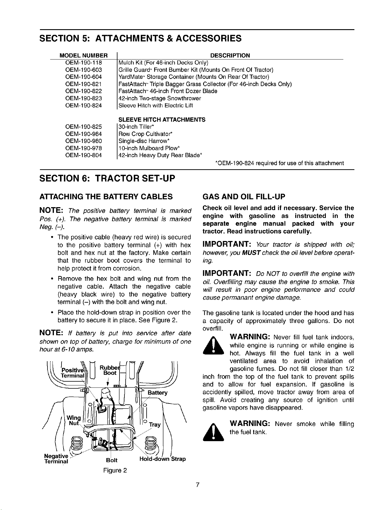
ATTACHING THE BATTERY CABLES
NOTE: The positive battery terminal is marked
Pos. (+). The negative battery terminal is marked
Neg. (-).
• The positive cable (heavy red wire) is secured
to the positive battery terminal (+) with hex
bolt and hex nut at the factory. Make certain
that the rubber boot covers the terminal to
help protect it from corrosion.
• Remove the hex bolt and wing nut from the
negative cable. Attach the negative cable
(heavy black wire) to the negative battery
terminal (-) with the bolt and wing nut.
• Place the hold-down strap in position over the
battery to secure it in place. See Figure 2.
NOTE: If battery is put into service after date
shown on top of battery, charge for minimum of one
hour at 6-10 amps.
I I
Negative
Terminal
Figure 2
ry
IV Tray
Jl
Ho_ld-clo_ trap
GAS AND OIL FILL-UP
Check oil level and add if necessary. Service the
engine with gasoline as instructed in the
separate engine manual packed with your
tractor. Read instructions carefully.
IMPORTANT: Your tractor is shipped with oil;
however, you MUST check the oil level before operat-
ing.
IMPORTANT: Do NOT to overfill the engine with
oil. Overfilling may cause the engine to smoke. This
will result in poor engine performance and could
cause permanant engine damage.
The gasoline tank is located under the hood and has
a capacity of approximately three gallons. Do not
overfill.
,_ WARNING: Never fill fuel tank indoors,
while engine is running or while engine is
hot. Always fill the fuel tank in a well
ventilated area to avoid inhalation of
gasoline fumes. Do not fill closer than 1/2
inch from the top of the fuel tank to prevent spills
and to allow for fuel expansion. If gasoline is
accidently spilled, move tractor away from area of
spill. Avoid creating any source of ignition until
gasoline vapors have disappeared.
,_ WARNING: Never smoke while filling
the fuel tank.
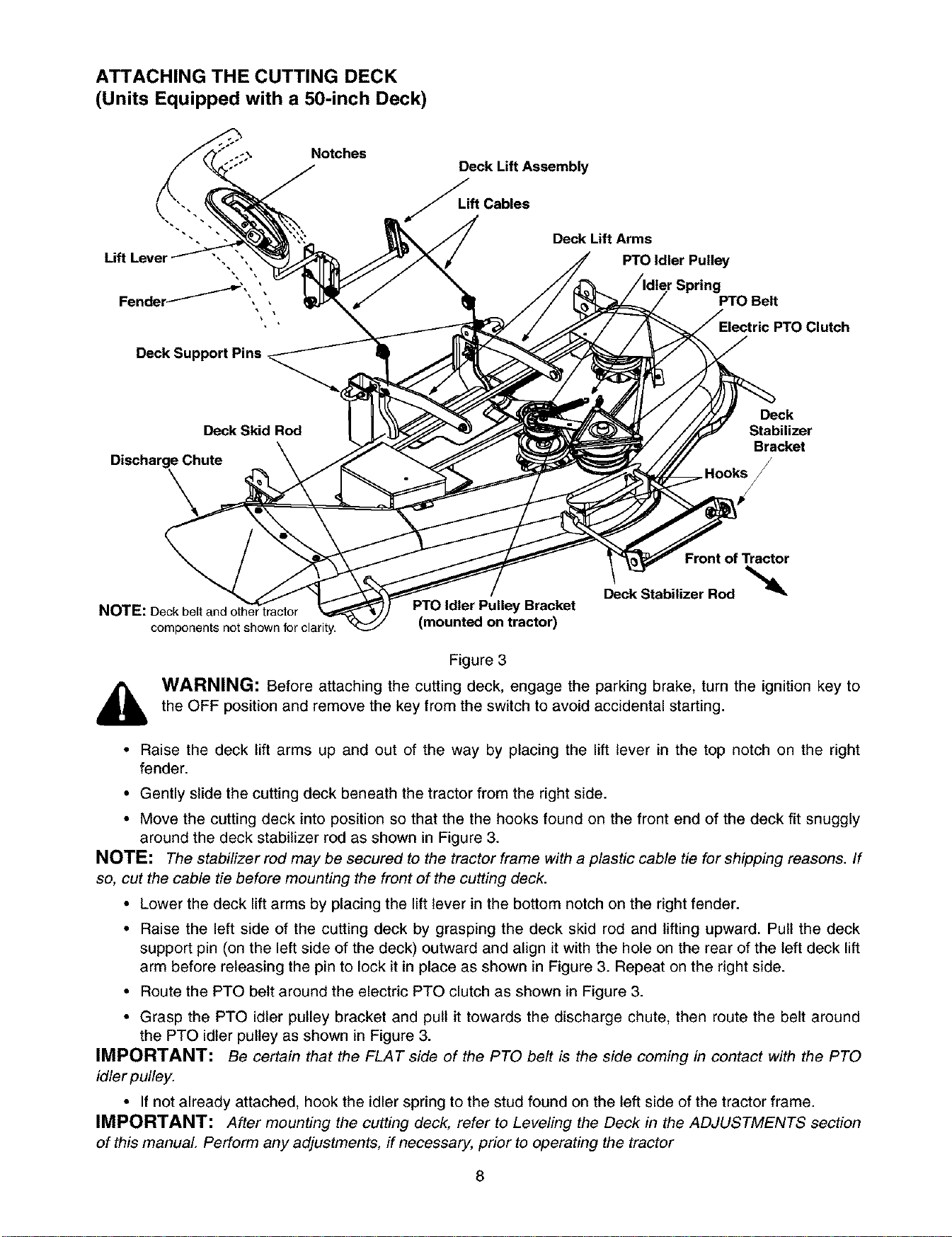
ATTACHING THE CUTTING DECK
(Units Equipped with a 50-inch Deck)
Notches
Deck Lift Assembly
ft Cables
Deck Lift Arms
PTO Idler Pulley
r Spring
PTO Belt
Deck Support Pins
Deck Skid Rod
DischargeChute
\
Deck
Stabilizer
Bracket
Front of Tractor
Deck Stabilizer Rod "_
components not shown for clarity.
PTOIdler Pulley Bracket
(mounted on tractor)
Figure 3
,_ WARNING: Before attaching the cutting deck, engage the parking brake, turn the ignition key to
the OFF position and remove the key from the switch to avoid accidental starting.
• Raise the deck lift arms up and out of the way by placing the lift lever in the top notch on the right
fender.
• Gently slide the cutting deck beneath the tractor from the right side.
• Move the cutting deck into position so that the the hooks found on the front end of the deck fit snuggly
around the deck stabilizer rod as shown in Figure 3.
NOTE: The stabilizer rod may be secured to the tractor frame with a plastic cable tie for shipping reasons. If
so, cut the cable tie before mounting the front of the cutting deck.
• Lower the deck lift arms by placing the lift lever in the bottom notch on the right fender.
• Raise the left side of the cutting deck by grasping the deck skid rod and lifting upward. Pull the deck
support pin (on the left side of the deck) outward and align it with the hole on the rear of the left deck lift
arm before releasing the pin to lock it in place as shown in Figure 3. Repeat on the right side.
• Route the PTO belt around the electric PTO clutch as shown in Figure 3.
• Grasp the PTO idler pulley bracket and pull it towards the discharge chute, then route the belt around
the PTO idler pulley as shown in Figure 3.
IMPORTANT: Be certain that the FLAT side of the PTO belt is the side coming in contact with the PTO
idler pulley.
• If not already attached, hook the idler spring to the stud found on the left side of the tractor frame.
IMPORTANT: After mounting the cutting deck, refer to Leveling the Deck in the ADJUSTMENTS section
of this manual Perform any adjustments, if necessary, prior to operating the tractor
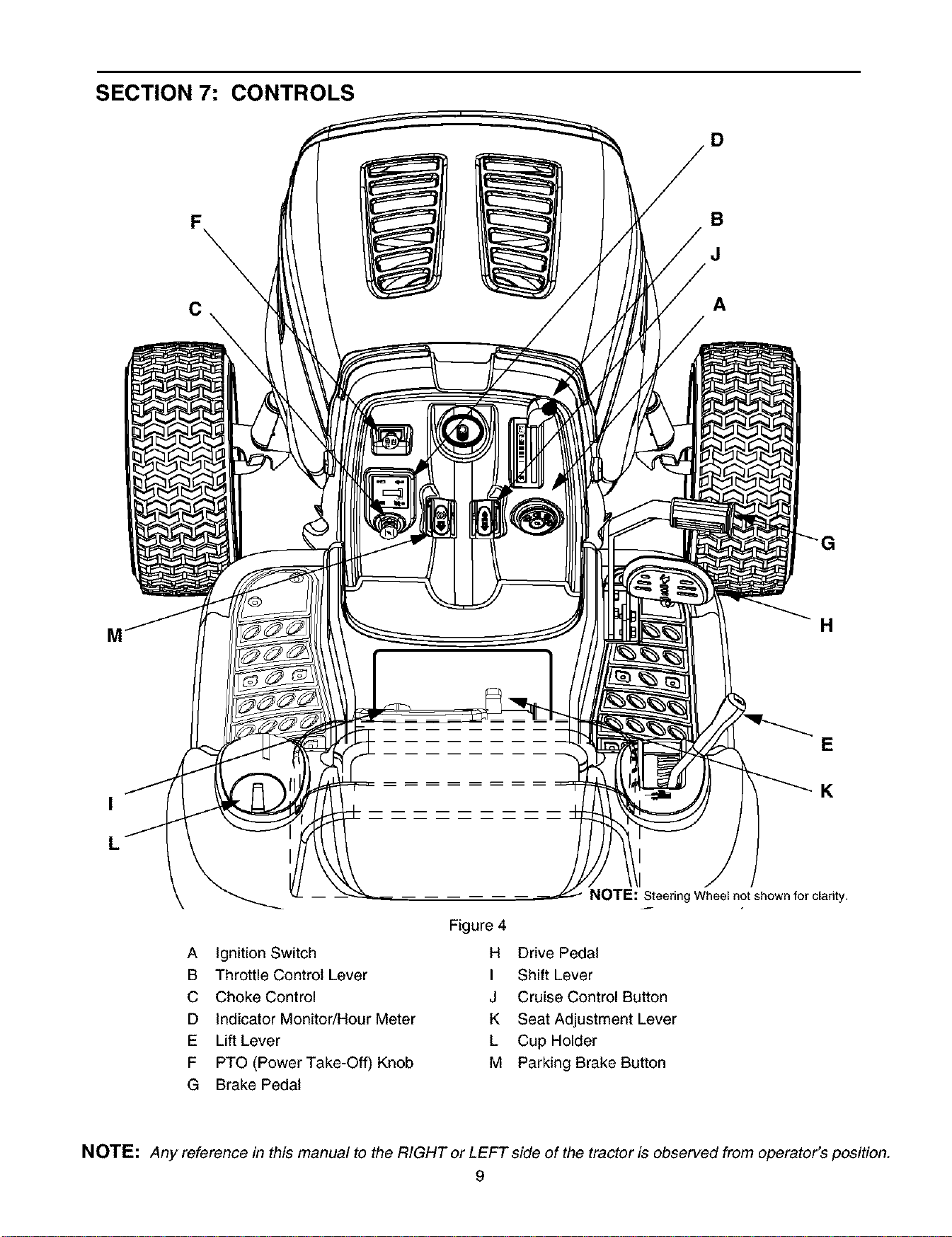
SECTION 7: CONTROLS
D
C
B
J
A
H
K
A Ignition Switch
B Throttle Control Lever
C Choke Control
D Indicator Monitor/Hour Meter
E Lift Lever
F PTO (Power Take-Off) Knob
G Brake Pedal
NOTE: Steering Wheel not shown for clarity.
Figure 4
H Drive Pedal
I Shift Lever
J Cruise Control Button
K Seat Adjustment Lever
L Cup Holder
M Parking Brake Button
NOTE: Any reference in this manual to the RIGHT or LEFT side of the tractor is observed from operator's position.
9
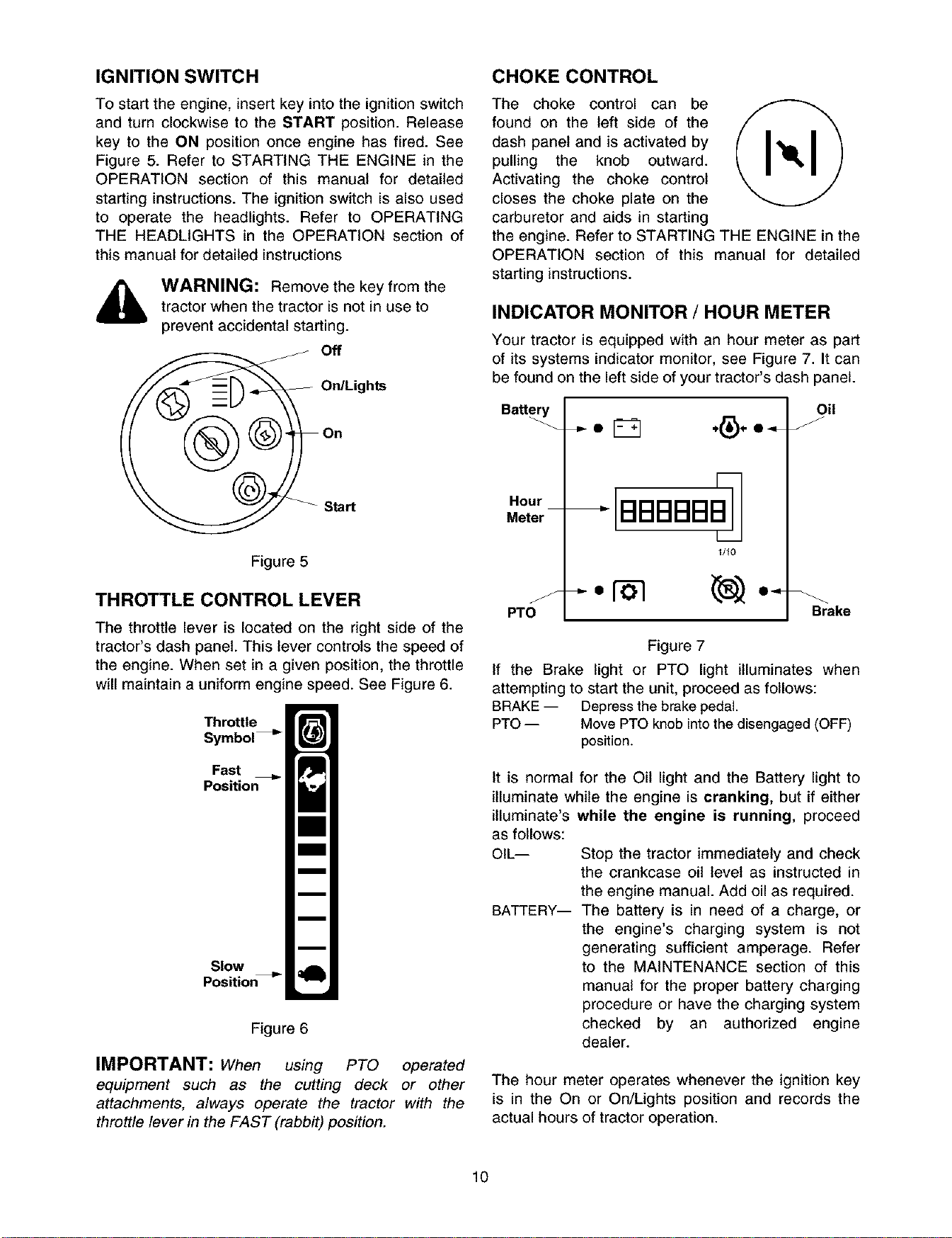
IGNITION SWITCH
To start the engine, insert key into the ignition switch
and turn clockwise to the START position. Release
key to the ON position once engine has fired. See
Figure 5. Refer to STARTING THE ENGINE in the
OPERATION section of this manual for detailed
starting instructions. The ignition switch is also used
to operate the headlights. Refer to OPERATING
THE HEADLIGHTS in the OPERATION section of
this manual for detailed instructions
WARNING: Remove the key from the
tractor when the tractor is not in use to
prevent accidental starting.
_._ Off
On/Lights
Start
Figure 5
THROTTLE CONTROL LEVER
The throttle lever is located on the right side of the
tractor's dash panel. This lever controls the speed of
the engine. When set in a given position, the throttle
will maintain a uniform engine speed. See Figure 6.
Throttle
Symbol
Fast
Position
Slow
Positio_
Figure 6
IMPORTANT: When using PTO operated
equipment such as the cutting deck or other
attachments, always operate the tractor with the
throttle lever in the FAST (rabbit)position.
CHOKE CONTROL
The choke control can be
found on the left side of the
dash panel and is activated by
pulling the knob outward.
Activating the choke control
closes the choke plate on the
carburetor and aids in starting
the engine. Refer to STARTING THE ENGINE in the
OPERATION section of this manual for detailed
starting instructions.
INDICATOR MONITOR / HOUR METER
Your tractor is equipped with an hour meter as part
of its systems indicator monitor, see Figure 7. It can
be found on the left side of your tractor's dash panel.
Batt_
Hour
Meter
Y
PTO
BBBBBB,
1/10
Oil
Brake
Figure 7
If the Brake light or PTO light illuminates when
attempting to start the unit, proceed as follows:
BRAKE -- Depress the brake pedal.
PTO -- Move PTO knob into the disengaged (OFF)
position.
It iS normal for the Oil light and the Battery light to
illuminate while the engine is cranking, but if either
itluminate's while the engine is running, proceed
as follows:
OIL-- Stop the tractor immediately and check
the crankcase oil level as instructed in
the engine manual. Add oil as required.
BATTERY-- The battery is in need of a charge, or
the engine's charging system is not
generating sufficient amperage. Refer
to the MAINTENANCE section of this
manual for the proper battery charging
procedure or have the charging system
checked by an authorized engine
dealer.
The hour meter operates whenever the ignition key
is in the On or On/Lights position and records the
actual hours of tractor operation.
10
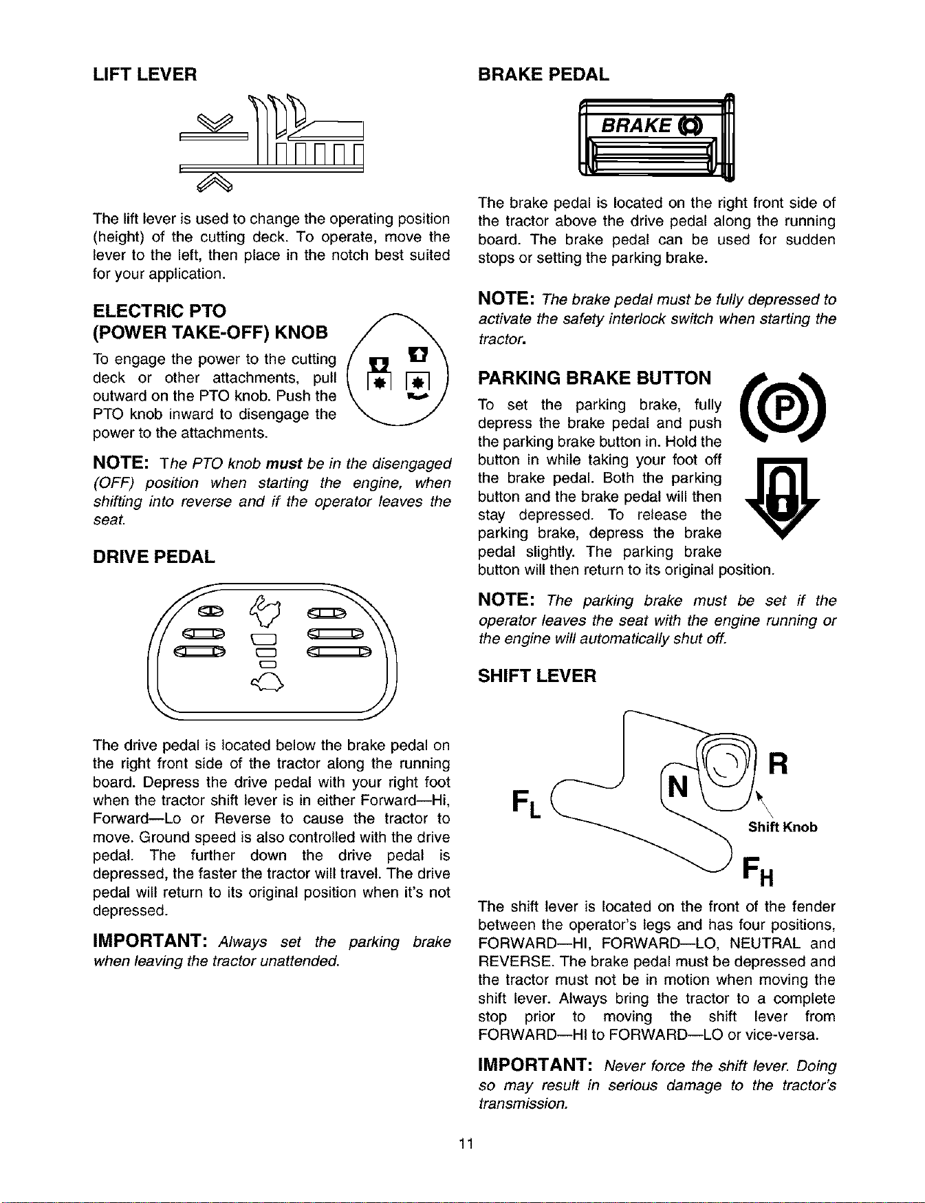
LIFT LEVER
, nnnnnrl
The lift lever is used to change the operating position
(height) of the cutting deck. To operate, move the
lever to the left, then place in the notch best suited
for your application.
ELECTRIC PTO
(POWER TAKE-OFF) KNOB
To engage the power to the cutting
deck or other attachments, pull
outward on the PTO knob. Push the
PTO knob inward to disengage the
power to the attachments.
NOTE: The PTO knob must be in the disengaged
(OFF) position when starting the engine, when
shifting into reverse and if the operator leaves the
seat.
DRIVE PEDAL
©
The drive pedal is located below the brake pedal on
the right front side of the tractor along the running
board. Depress the drive pedal with your right foot
when the tractor shift lever is in either Forward--Hi,
Forward--Lo or Reverse to cause the tractor to
move. Ground speed is also controlled with the drive
pedal. The further down the drive pedal is
depressed, the faster the tractor will travel. The drive
pedal will return to its original position when it's not
depressed.
IMPORTANT: Always set the parking brake
when leaving the tractor unattended.
BRAKE PEDAL
The brake pedal is located on the right front side of
the tractor above the drive pedal along the running
board. The brake pedal can be used for sudden
stops or setting the parking brake.
NOTE: The brake pedal must be fully depressed to
activate the safety interlock switch when starting the
tractor.
PARKING BRAKE BUTTON
To set the parking brake, fully
depress the brake pedal and push
the parking brake button in. Hold the
button in while taking your foot off
the brake pedal. Both the parking
button and the brake pedal will then
stay depressed. To release the
parking brake, depress the brake
pedal slightly. The parking brake
button will then return to its original position.
NOTE: The parking brake must be set if the
operator leaves the seat with the engine running or
the engine will automatically shut off.
SHIFT LEVER
The shift lever is located on the front of the fender
between the operator's legs and has four positions,
FORWARD--HI, FORWARD--LO, NEUTRAL and
REVERSE. The brake pedal must be depressed and
the tractor must not be in motion when moving the
shift lever. Always bring the tractor to a complete
stop prior to moving the shift lever from
FORWARD--HI to FORWARD--LO or vice-versa.
IMPORTANT: Never force the shift lever. Doing
so may result in serious damage to the tractor's
transmission.
11
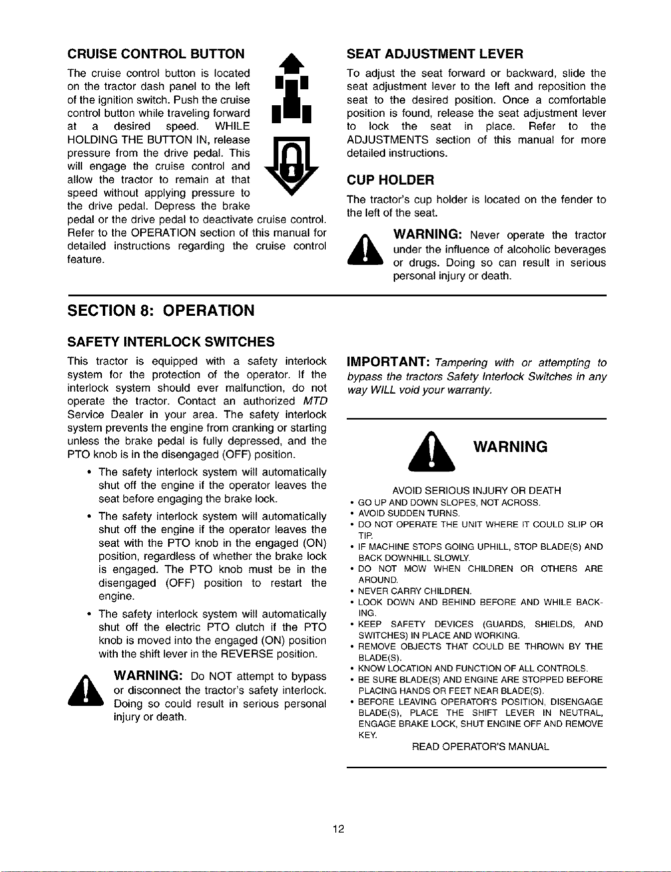
CRUISE CONTROL BUTTON
The cruise control button is located
on the tractor dash panel to the left
of the ignition switch. Push the cruise
control button while traveling forward
at a desired speed. WHILE
HOLDING THE BUTTON IN, release
pressure from the drive pedal. This
will engage the cruise control and
allow the tractor to remain at that
speed without applying pressure to
the drive pedal. Depress the brake
6
pedal or the drive pedal to deactivate cruise control.
Refer to the OPERATION section of this manual for
detailed instructions regarding the cruise control
feature.
SEAT ADJUSTMENT LEVER
To adjust the seat forward or backward, slide the
seat adjustment lever to the left and reposition the
seat to the desired position. Once a comfortable
position is found, release the seat adjustment lever
to lock the seat in place. Refer to the
ADJUSTMENTS section of this manual for more
detailed instructions.
CUP HOLDER
The tractor's cup holder is located on the fender to
the left of the seat.
WARNING: Never operate the tractor
under the influence of alcoholic beverages
or drugs. Doing so can result in serious
personal injury or death.
SECTION 8: OPERATION
SAFETY INTERLOCK SWITCHES
This tractor is equipped with a safety interlock
system for the protection of the operator. If the
interlock system should ever malfunction, do not
operate the tractor. Contact an authorized MTD
Service Dealer in your area. The safety interlock
system prevents the engine from cranking or starting
unless the brake pedal is fully depressed, and the
PTO knob is in the disengaged (OFF) position.
• The safety interlock system will automatically
shut off the engine if the operator leaves the
seat before engaging the brake lock.
• The safety interlock system will automatically
shut off the engine if the operator leaves the
seat with the PTO knob in the engaged (ON)
position, regardless of whether the brake lock
is engaged. The PTO knob must be in the
disengaged (OFF) position to restart the
engine.
• The safety interlock system will automatically
shut off the electric PTO clutch if the PTO
knob is moved into the engaged (ON) position
with the shift lever in the REVERSE position.
WARNING: Do NOT attempt to bypass
or disconnect the tractor's safety interlock.
Doing so could result in serious personal
injury or death.
IMPORTANT: Tampering with or attempting to
bypass the tractors Safety Interlock Switches in any
way WILL void your warranty.
WARNING
AVOID SERIOUS INJURY OR DEATH
• GO UP AND DOWN SLOPES, NOT ACROSS.
• AVOID SUDDEN TURNS.
• DO NOT OPERATE THE UNIT WHERE IT COULD SLIP OR
T_P.
• IF MACHINE STOPS GOING UPHILL, STOP BLADE(S) AND
BACK DOWNHILL SLOWLY.
• DO NOT MOW WHEN CHILDREN OR OTHERS ARE
AROUND.
• NEVER CARRY CHILDREN.
• LOOK DOWN AND BEHIND BEFORE AND WHILE BACK-
ING.
• KEEP SAFETY DEVICES (GUARDS, SHIELDS, AND
SWITCHES) IN PLACE AND WORKING.
• REMOVE OBJECTS THAT COULD BE THROWN BY THE
BLADE(S).
• KNOW LOCATION AND FUNCTION OF ALL CONTROLS.
• BE SURE BLADE(S) AND ENGINE ARE STOPPED BEFORE
PLACING HANDS OR FEET NEAR BLADE(S).
• BEFORE LEAVING OPERATOR'S POSITION, DISENGAGE
BLADE(S), PLACE THE SHIFT LEVER IN NEUTRAL,
ENGAGE BRAKE LOCK, SHUT ENGINE OFF AND REMOVE
KEY.
READ OPERATOR'S MANUAL
12
SETTING THE CUTTING HEIGHT
Select the height position of the cutting deck by
placing the deck lift lever in any of the six different
cutting height notches on the right side of the fender.
Then adjust the deck wheels, or rollers (on units
equipped with a 50" deck) so that they are at least
1/4 inch to 1/2 inch above the ground when the
tractor is on a smooth, flat surface such as a
driveway.
WARNING: Keep hands and feet away
from the discharge chute opening of the
cutting deck.
NOTE: The deck wheels (on units equipped with a
46-inch deck) are an anti-scalp feature of the deck
and are not designed to support the weight of the
free-floating cutting deck.
Refer to the ADJUSTMENTS section of this manual
for more detailed instructions regarding various deck
adjustments.
STARTING THE ENGINE
NOTE: Do NOT leave the choke control out while
operating the tractor. Doing so will result in a "rich"
fuel mixture and cause the engine to run poorly.
STOPPING THE ENGINE
• Place the PTO knob into the disengaged
(OFF) position
• Move the throttle control into the SLOW
position and allow the engine to "idle down"
for ten seconds, then turn the ignition key
counterclockwise to the OFF position.
• Remove the key from the ignition switch to
prevent accidental starting.
IMPORTANT: If you think you've struck a foreign
object, stop the engine immediately Remove the
wire(s) from the spark plug(s), thoroughly inspect the
unit for any damage, and repair the damage before
restarting and operating the tractor.
DRIVING THE TRACTOR
,£k
NOTE:
Refer to the TRACTOR SET-UP section of
this manual for Gasoline and Oil fill up instructions.
• Insert the tractor key into the ignition switch.
• Place the PTO knob into the disengaged
(OFF) position.
• Depress the brake pedal and set the parking
brake.
• Move the shift lever into the NEUTRAL
position.
• Move the throttle control lever into the FAST
(rabbit) position.
• Pull out the choke control knob, if so equipped
A warm engine may not require choking.
• Turn the ignition key clockwise to the START
position. After the engine starts, release the
key. It will return to the ON position.
IMPORTANT: Do NOT hold the key in the START
position for longer than ten seconds at a time. Doing
so may cause damage to your engine's starter.
NOTE: If starting problems are encountered, refer
to the TROUBLESHOOTING section of this manual
After the engine starts, slowly release the brake
pedal. As the engine warms up, gradually push the
choke control knob inward to open up the choke
plate on the engine's carburetor.
WARNING: Avoid sudden starts,
excessive speed and sudden stops.
WARNING: Do not leave the seat of the
tractor without first placing the PTO knob in
the disengaged (OFF) position, depressing
the brake pedal and engaging the parking
brake. If leaving the tractor unattended,
also turn the ignition key off and remove
the key.
• Depress the brake pedal to release the
parking brake and let the pedal up. Move the
throttle lever into the FAST (rabbit) position.
IMPORTANT: Do NOT use the shift lever to
change the direction of travel or the speed range
when the tractor is in motion. Use the brake pedal to
bring the tractor to a complete stop before shifting.
• To move forward, move the shift lever into the
FORWARD--Hi or FORWARD--Lo position,
then slowly depress the drive pedal until the
desired speed is achieved.
NOTE: Operate the tractor with the shift lever in
the FORWARD--Lo position for towing, climbing
and other heavy load applications. Operate the
tractor with the shift lever in the FORWARD--Hi
position for all other applications.
• To move in reverse, move the shift lever into
the REVERSE position, check that the area
behind is clear then slowly depress the drive
pedal.
13
SETTING THE CRUISE CONTROL
NOTE: The cruise control feature should only be
utilized in the forward direction.
• Move the shift lever into either the
FORWARD--Hi or FORWARD--Lo position,
then slowly depress the drive pedal until the
desired speed is achieved.
• Lightly push the cruise control button
downward.
• While continuing to hold the cruise button
down, lift your foot from the drive pedal (you
should feet the cruise latch engage).
• If properly engaged, the cruise control button
and the drive pedal should lock in the down
position, and the tractor will maintain the same
forward speed.
• Disengage the cruise control using one of the
following methods:
Depress the brake pedal to disengage the
cruise control and stop the tractor.
Lightly depress the drive pedal
To change to the reverse direction when operating
with cruise control, depress the brake pedal to
disengage the cruise control and bring the tractor to
a complete stop. Then move the shift lever into the
REVERSE position and depress the drive pedal.
DRIVING ON SLOPES
Refer to the SLOPE GAUGE on page 6 to help
determine slopes where you may not operate safely.
_1_ WARNING: DO not mow on inclines with
a slope in excess of 15 degrees (a rise of
approximately 2-1/2 feet every 10 feet).
The tractor could overturn and cause
serious injury.
Operate the tractor up and down slopes, never
across slopes. Do not drive so that the tractor may
tip over sideways.
Before operating the tractor on any slope, walk the
slope to look for possible hazards such as rocks.
mounds, ruts, stumps or other surface irregularities
which could cause the tractor to be upset.
Avoid turns when driving on a slope. If a turn must
be made, turn down the slope. Turning up a slope
greatly increases the chance of a roll over.
Avoid stopping when driving up a slope. If it is
necessary to stop while driving up a slope, start up
smoothly and carefully to reduce the possibility of
flipping the tractor over backward.
OPERATING THE HEADLIGHTS
To turn the tractor's headlights on:
• Start the engine following the instructions
earlier in this section.
• Turn the key one notch counterclockwise into
the On/Lights position of the ignition switch.
Refer to Figure 5.
To turn the tractor's headlights off:
• Turn the key into either the On position (to
leave the engine running) or the Off position
(to shut the engine off). Refer to Figure 5.
IMPORTANT: Never move the key into the Start
position while the engine is running. Doing so may
cause damage to your engine's starter.
STOPPING THE ENGINE
• Place the PTO knob into the disengaged
(OFF) position.
• Move the throttle control into the SLOW
(turtle) position and allow the engine to "idle
down" for ten seconds, then turn the ignition
key counterclockwise to the OFF position.
• Remove the key from the ignition switch to
prevent accidental starting.
IMPORTANT: If you think you've struck a foreign
object, stop the engine immediately Remove the
wire(s) from the spark plug(s), thoroughly inspect the
unit for any damage, and repair the damage before
restarting and operating the mowe_
USING THE LIFT LEVER
To raise the cutting deck, move the lift lever to the
left, then place it in the notch best suited for your
application. Refer to SETTING THE CUTTING
HEIGHT earlier in this section.
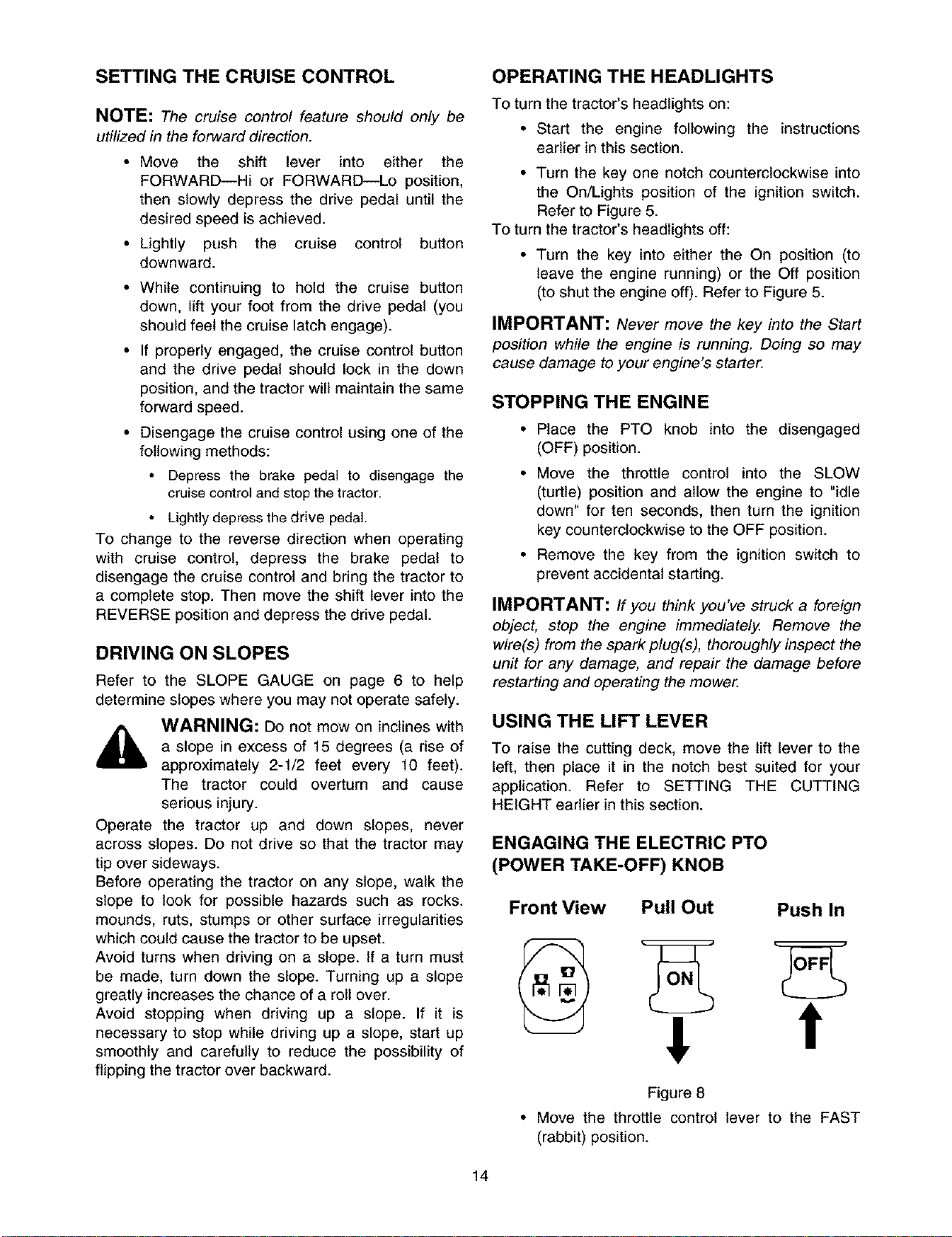
ENGAGING THE ELECTRIC PTO
(POWER TAKE-OFF) KNOB
Front View Pull Out Push In
! t
Figure 8
• Move the throttle control lever to the FAST
(rabbit) position.
14
• Pullthe PTOknoboutwardintotheengaged
(ON)position.SeeFigure8.
• Keepthe throttleleverin the FAST(rabbit)
positionfor the most efficient use of the
cutting deck and other attachments.
• The operator must remain in the tractor seat
at all times. If the operator should leave the
seat without pushing the PTO knob inward
into the disengaged (OFF) position, the
tractor's engine will shut off.
IMPORTANT: The PTO knob cannot be in the
engaged (ON) position when the tractor is driving in
the reverse direction. The PTO knob must be in the
disengaged (OFF) position when the shift lever is in
REVERSE or the PTO will automatically shut off.
Refer to SAFETY INTERLOCK SWITCHES in this
section.
MOWING
This tractor is equipped with one of MTD's high
quality cutting decks. The following information will
be helpful when using the cutting deck with your
tractor.
WARNING: To avoid possible injury, do
not allow anyone in the area of the tractor
while mowing. Even if the area to be
mowed has been cleared of foreign
objects, small objects may be picked up
and discharged by the mower.
,_ WARNING: Never direct the discharge
of material toward bystanders or allow
anyone near the machine while in
operation.
• For best results it is recommended that the
first two laps should be cut with the discharge
thrown towards the center. After the first two
laps, reverse the direction to throw the
discharge to the outside for the balance of
cutting. This will give a better appearance to
the lawn.
• Do not cut the grass too short. Short grass
invites weed growth and yellows quickly in dry
weather.
• Mowing should always be done with the
engine at full throttle.
• Do not mow at high ground speed, especially
if a mulch kit or grass collector is installed.
• Under heavier conditions it may be necessary
to go back over the cut area a second time to
get a clean cut.
• Do NOT attempt to mow heavy brush and
weeds and extremely tall grass. Your tractor is
designed to mow lawns, NOT clear brush.
• Keep the blades sharp and replace the blades
when worn. Refer to the MAINTENANCE
section of this manual for proper blade
sharpening instructions.
SECTION 9: ADJUSTMENTS
LEVELING THE DECK
WARNING: Cutting blades are sharp. Always protect your hands by wearing heavy leather work
gloves to grasp blades.
NOTE: Checkthetractor'stirepressurebeforeperforminganydecklevelingadjustments. Referto TIRESin
the maintenance section of this manual for further information regarding tire pressure.
Front to Rear
The front of the cutting deck is supported by a stabilizer bar that can adjusted to level the deck from front to
rear. The front of the deck should be 1/4" to 3/8" lower than the rear of the deck. Adjust if necessary as follows:
WARNING: Turn the tractor's engine off, remove the key from the ignition switch and apply the
tractor's parking brake before making any adjustments to the cutting deck.
• With the tractor parked on a firm, level surface, place the lift lever in the top notch (highest position) and
rotate the blade nearest the discharge chute so that it's parallel with the tractor.
• Measure the distance from the front of the blade tip to the ground and the distance from the rear of the
blade tip to the ground. The first measurement taken should be between 1/4" and 3/8" less than the
second measurement. Determine the approximate distance necessary for proper adjustment and
proceed, if necessary, to the next step.
15
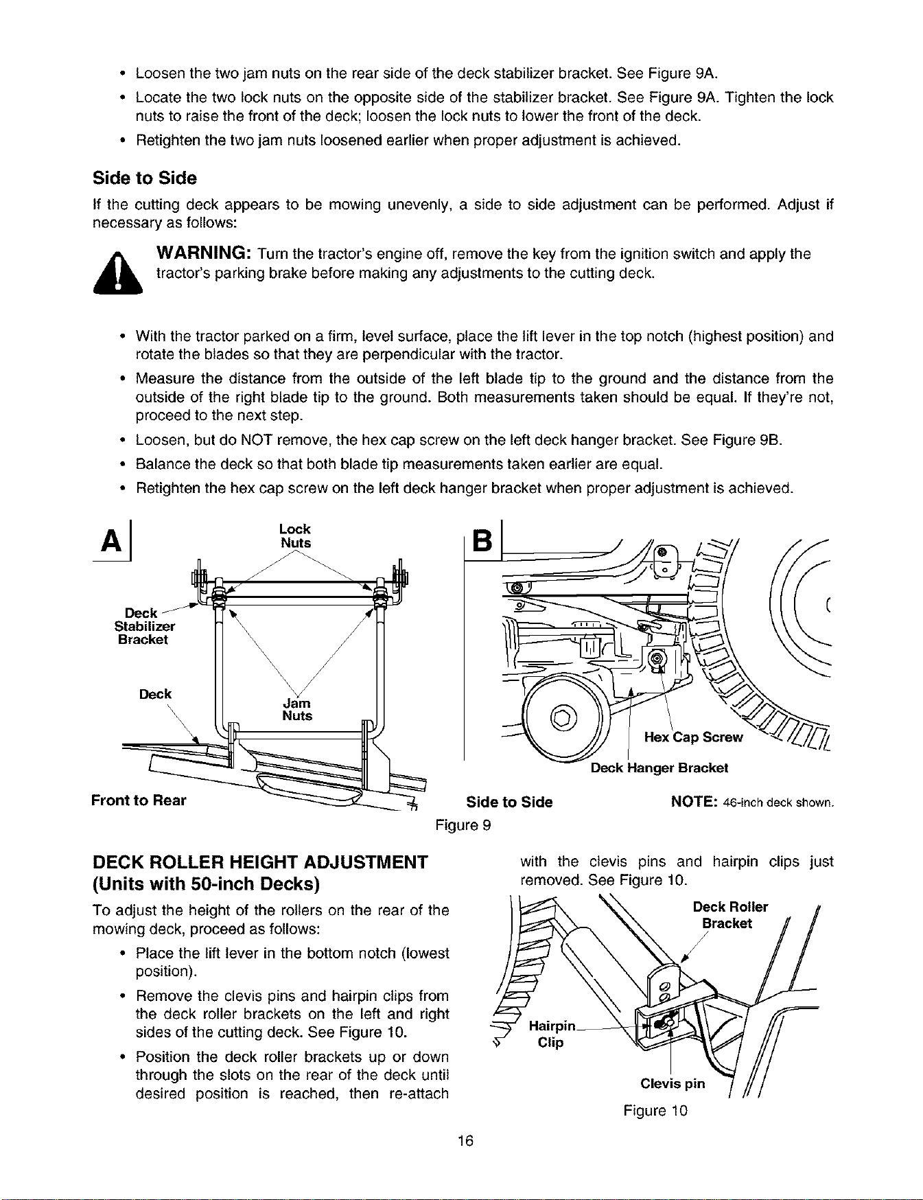
• Loosenthetwojamnutsontherearsideofthedeckstabilizerbracket.SeeFigure9A.
• Locatethetwolocknutsontheoppositesideof thestabilizerbracket.SeeFigure9A.Tightenthelock
nutsto raisethefrontofthedeck;loosenthelocknutstolowerthefrontofthedeck.
• Retightenthetwojamnutsloosenedearlierwhenproperadjustmentisachieved.
Side to Side
If the cutting deck appears to be mowing unevenly, a side to side adjustment can be performed. Adjust if
necessary as follows:
WARNING: Turn the tractor's engine off, remove the key from the ignition switch and apply the
tractor's parking brake before making any adjustments to the cutting deck.
• With the tractor parked on a firm, level surface, place the lift lever in the top notch (highest position) and
rotate the blades so that they are perpendicular with the tractor.
• Measure the distance from the outside of the left blade tip to the ground and the distance from the
outside of the right blade tip to the ground. Both measurements taken should be equal. If they're not,
proceed to the next step.
• Loosen, but do NOT remove, the hex cap screw on the left deck hanger bracket. See Figure 9B.
• Balance the deck so that both blade tip measurements taken earlier are equal.
• Retighten the hex cap screw on the left deck hanger bracket when proper adjustment is achieved.
Stabilizer
Bracket
Lock
Nuts
Frontto Rear
Side to Side
Figure 9
DECK ROLLER HEIGHT ADJUSTMENT
(Units with 50-inch Decks)
To adjust the height of the rollers on the rear of the
mowing deck, proceed as follows:
• Place the lift lever in the bottom notch (lowest
position).
• Remove the clevis pins and hairpin clips from
the deck roller brackets on the left and right
sides of the cutting deck. See Figure 10.
• Position the deck roller brackets up or down
through the slots on the rear of the deck until
desired position is reached, then re-attach
16
Screw
Deck Hanger Bracket
NOTE: 46-inch deck shown.
with the clevis pins and hairpin clips just
removed. See Figure 10.
_?CrakcReOltler_
Clip _,ev!spin_,,,_/_j
Figure 10
NOTE: Be certain that the left roller bracket and
the right roller bracket are set in the same position.
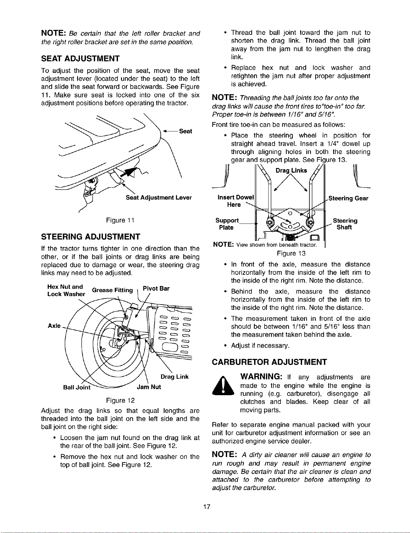
SEAT ADJUSTMENT
To adjust the position of the seat, move the seat
adjustment lever (located under the seat) to the left
and slide the seat forward or backwards. See Figure
11. Make sure seat is locked into one of the six
adjustment positions before operating the tractor.
Seat Adjustment Lever
Figure 11
STEERING ADJUSTMENT
If the tractor turns tighter in one direction than the
other, or if the ball joints or drag links are being
replaced due to damage or wear, the steering drag
links may need to be adjusted.
HexNut and Grease Fitting i Pivot Bar
Lock Washer
Axle ==_ _ c=_
/ \ Drag Link
BallJoint"_ Jam Nut
Figure 12
Adjust the drag links so that equal lengths are
threaded into the ball joint on the left side and the
ball joint on the right side:
• Loosen the jam nut found on the drag link at
the rear of the ball joint. See Figure 12.
• Remove the hex nut and lock washer on the
top of ball joint. See Figure 12.
• Thread the ball joint toward the jam nut to
shorten the drag link. Thread the ball joint
away from the jam nut to lengthen the drag
link.
• Replace hex nut and lock washer and
retighten the jam nut after proper adjustment
is achieved.
NOTE: Threading the ball joints too far onto the
drag links will cause the front tires to"toe-in" too far.
Proper toe-in is between 1/16" and 5/16".
Front tire toe-in can be measured as follows:
• Place the steering wheel in position for
straight ahead travel. Insert a 1/4" dowel up
through aligning holes in both the steering
gear and support plate. See Figure 13.
InsertDowelll II II ].SteeringGear
Here _
Support_ _0_ _ _-_ _ I- Steering
Plate I_ Shaft
NOTE: View shown from beneath tractor.
Figure 13
• In front of the axle, measure the distance
horizontally from the inside of the left rim to
the inside of the right rim. Note the distance.
• Behind the axle, measure the distance
horizontally from the inside of the left rim to
the inside of the right rim. Note the distance.
• The measurement taken in front of the axle
should be between 1/16" and 5/16" less than
the measurement taken behind the axle.
• Adjust if necessary.
CARBURETOR ADJUSTMENT
WARNING: If any adjustments are
made to the engine while the engine is
running (e.g. carburetor), disengage all
clutches and blades. Keep clear of all
moving parts.
Refer to separate engine manual packed with your
unit for carburetor adjustment information or see an
authorized engine service dealer.
NOTE: A dirty air cleaner will cause an engine to
run rough and may result in permanent engine
damage. Be certain that the air cleaner is clean and
attached to the carburetor before attempting to
adjust the carburetor.
17
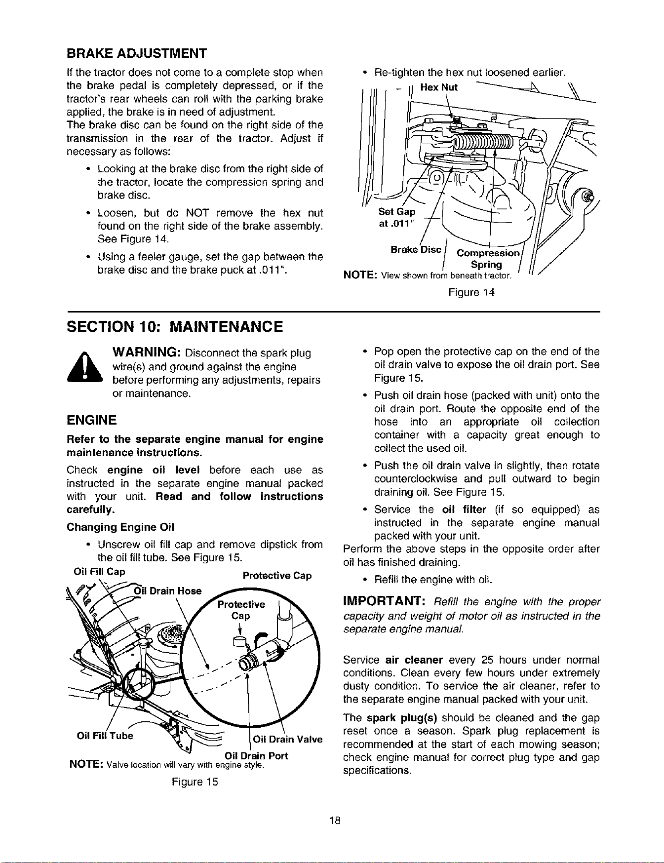
BRAKE ADJUSTMENT
If the tractor does not come to a complete stop when
the brake pedal is completely depressed, or if the
tractor's rear wheels can roll with the parking brake
applied, the brake is in need of adjustment.
The brake disc can be found on the right side of the
transmission in the rear of the tractor. Adjust if
necessary as follows:
• Looking at the brake disc from the right side of
the tractor, locate the compression spring and
brake disc.
• Loosen, but do NOT remove the hex nut
found on the right side of the brake assembly.
See Figure 14.
• Using a feeler gauge, set the gap between the
brake disc and the brake puck at .011".
• Re-tighten the hex nut loosened earlier.
Set Gap __-I _"_ _)// ""_J
at .011" /-_///_
Bra.eDisc/ y /
¢ Spring III/
NOTE: Viewshownfrombeneathtractor.
Figure 14
SECTION 10: MAINTENANCE
WARNING: Disconnect the spark plug
wire(s) and ground against the engine
before performing any adjustments, repairs
or maintenance.
ENGINE
Refer to the separate engine manual for engine
maintenance instructions.
Check engine oil level before each use as
instructed in the separate engine manual packed
with your unit. Read and fellow instructions
carefully.
Changing Engine Oil
• Unscrew oit fill cap and remove dipstick from
the oil fitl tube. See Figure 15.
Oil Fill Cap Protective Cap
Pop open the protective cap on the end of the
oil drain valve to expose the oil drain port. See
Figure 15.
Push oil drain hose (packed with unit) onto the
oil drain port. Route the opposite end of the
hose into an appropriate oil collection
container with a capacity great enough to
collect the used oil.
• Push the oil drain valve in slightly, then rotate
counterclockwise and pult outward to begin
draining oit. See Figure 15.
• Service the oil filter (if so equipped) as
instructed in the separate engine manual
packed with your unit.
Perform the above steps in the opposite order after
oit has finished draining.
• Refill the engine with oil.
IMPORTANT: Refill the engine with the proper
capacity and weight of motor oil as instructed in the
separate engine manual.
Oil Fill Tube Oil Drain Valve
Oil Drain Port
NOTE: Valve location will vary with engine style.
Figure 15
Service air cleaner every 25 hours under normal
conditions. Clean every few hours under extremely
dusty condition. To service the air cleaner, refer to
the separate engine manual packed with your unit.
The spark plug(s) should be cleaned and the gap
reset once a season. Spark plug replacement is
recommended at the start of each mowing season;
check engine manual for correct plug type and gap
specifications.
18
CLEANING THE ENGINE AND DECK
Any fuel or oil spilled on the machine should be
wiped off promptly. Do NOT allow grass, leaves, and
dirt to accumulate around the cooling fins of the
engine or on any other part of the machine,
especially the pulleys and other moving parts.
Clean the underside of the deck with a wisk broom,
putty knife or forced air after each mowing.
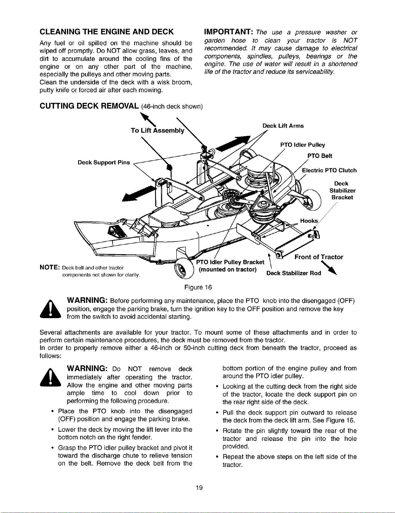
CUTTING DECK REMOVAL (46-inch deck shown)
\
To
Deck Support Pins
IMPORTANT: The use a pressure washer or
garden hose to clean your tractor is NOT
recommended. It may cause damage to electrical
components, spindles, pulleys, bearings or the
engine. The use of water will result in a shortened
life of the tractor and reduce its serviceability.
Deck Lift Arms
PTO Idler Pulley
PTO Belt
PTO Clutch
Deck
Stabilizer
Bracket
/
Hooks/
NOTE: Deck belt and other tractor
components not shown for clarity.
' Bracket _ Front of Tractor
(mounted on tractor)D/eck Stabilizer Rod%%_k
Figure 16
,_ WARNING: Before performing any maintenance, place the PTO knob into the disengaged (OFF)
position, engage the parking brake, turn the ignition key to the OFF position and remove the key
from the switch to avoid accidental starting.
Several attachments are available for your tractor. To mount some of these attachments and in order to
perform certain maintenance procedures, the deck must be removed from the tractor.
In order to properly remove either a 46-inch or 50-inch cutting deck from beneath the tractor, proceed as
follows:
A WARNING: Do NOT remove deck
immediately after operating the tractor.
Allow the engine and other moving parts
ample time to cool down prior to
performing the following procedure.
• Place the PTO knob into the disengaged
(OFF) position and engage the parking brake.
• Lower the deck by moving the lift lever into the
bottom notch on the right fender.
• Grasp the PTO idler pulley bracket and pivot it
toward the discharge chute to relieve tension
on the belt. Remove the deck belt from the
bottom portion of the engine pulley and from
around the PTO idler pulley.
• Looking at the cutting deck from the right side
of the tractor, locate the deck support pin on
the rear right side of the deck.
• Pull the deck support pin outward to release
the deck from the deck lift arm. See Figure 16.
• Rotate the pin slightly toward the rear of the
tractor and release the pin into the hole
provided.
• Repeat the above steps on the left side of the
tractor.
19
• Move the lift lever into the top notch on the
right fender to raise the deck lift arms out of
the way.
• Gently slide the cutting deck toward the front
of the tractor allowing the hooks on the deck
to release themselves from the deck stabilizer
rod. Do NOT let the deck fall to the ground.
• Gently slide the cutting deck (from the right
side) out from underneath the tractor.
NOTE: To properly remount the cutting deck,
perform the above steps in reverse order. Having a
second person assist you will ease this procedure.
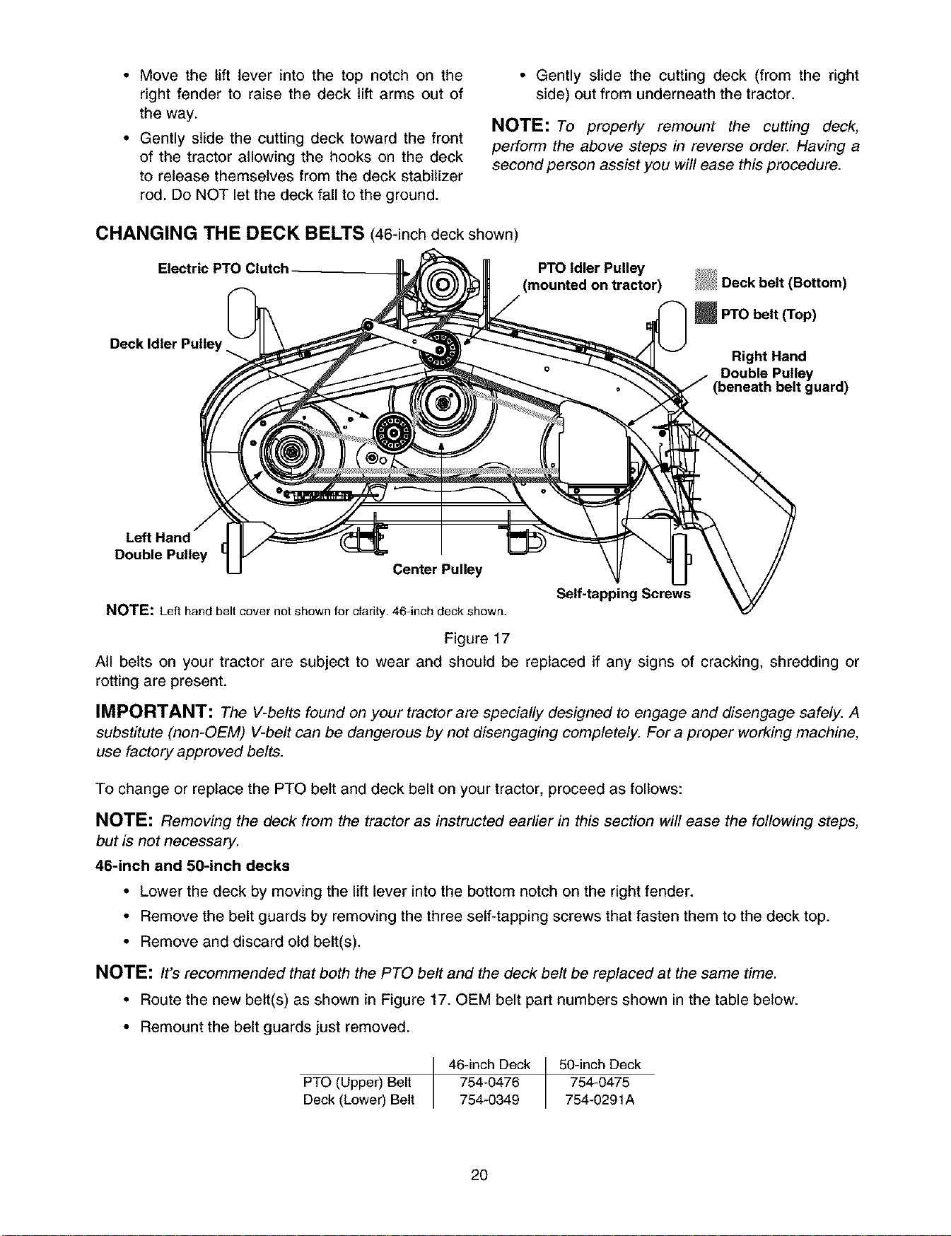
CHANGING THE DECK BELTS (46-inch deck shown)
Electric PTO Idler Pulley
(mounted on tractor)
Deck Idler Pulley
m PTO belt (Top)
Right Hand
Double PulleYuard )
Left Hand \
Double Pulley
Center Pulley
Self-tapping Screws
NOTE: Left hand belt cover not shown for clarity. 46-inch deck shown.
Figure 17
All belts on your tractor are subject to wear and should be replaced if any signs of cracking, shredding or
rotting are present.
IMPORTANT: The V-belts found on your tractor are specially designed to engage and disengage safely. A
substitute (non-OEM) V-belt can be dangerous by not disengaging completely. For a proper working machine,
use factory approved belts.
To change or replace the PTO belt and deck belt on your tractor, proceed as follows:
NOTE: Removing the deck from the tractor as instructed earlier in this section will ease the following steps,
but is not necessary.
46-inch and 50-inch decks
• Lower the deck by moving the lift lever into the bottom notch on the right fender.
• Remove the belt guards by removing the three self-tapping screws that fasten them to the deck top.
• Remove and discard old belt(s).
NOTE: It's recommended that both the PTO belt and the deck belt be replaced at the same time.
• Route the new belt(s) as shown in Figure 17. OEM belt part numbers shown in the table below.
• Remount the belt guards just removed.
PTO (Upper) Belt
Deck (Lower) Belt
46-inch Deck 50-inch Deck
754-0476 754-0475
754-0349 754-0291A
2O
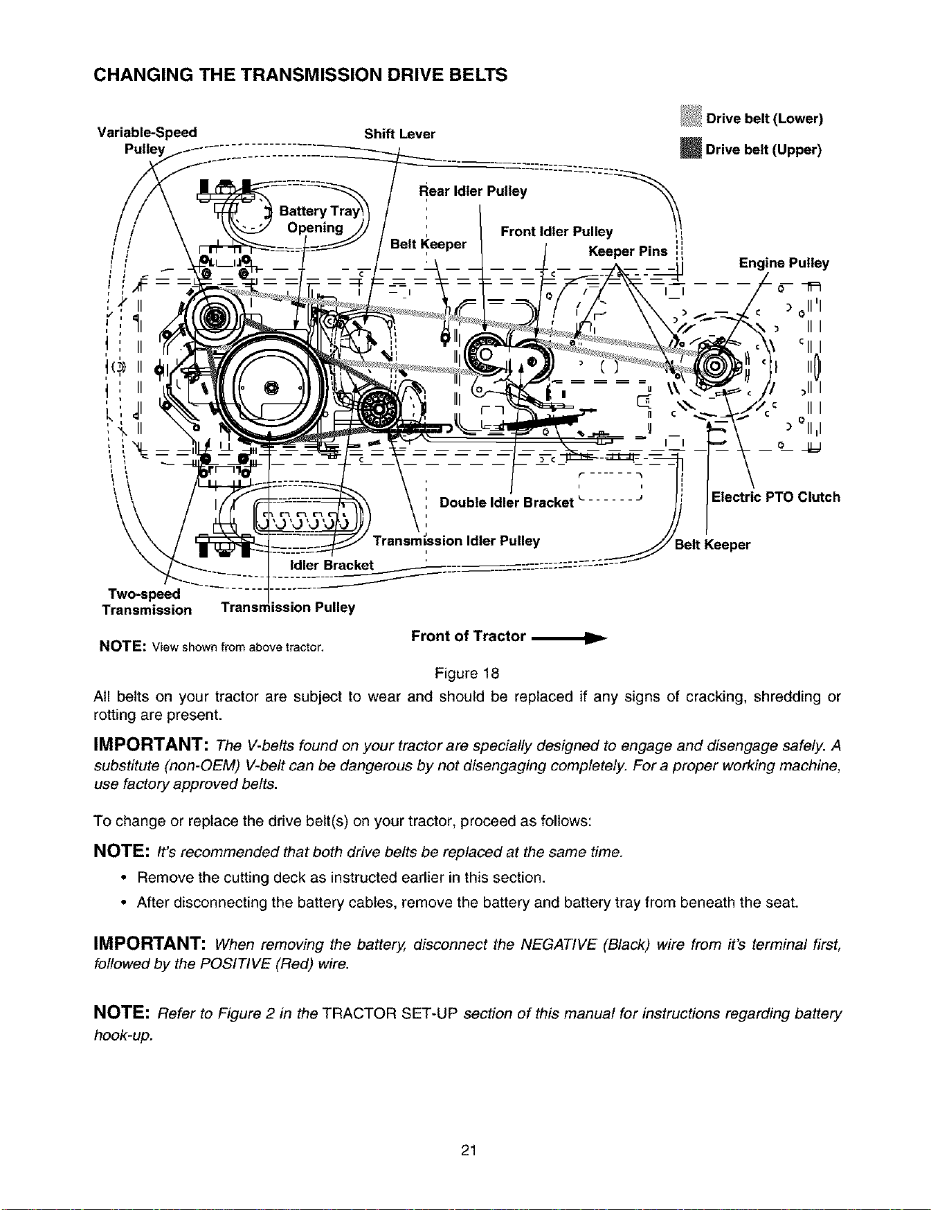
CHANGING THE TRANSMISSION DRIVE BELTS
Variable-Speed Shift Lever
_ Drive belt (Upper)
Engine Pulley
) oli'I
_III
II01
.c III
) °II,I
o
Electric PTO Clutch
Belt Keeper
Two-speed
Transmission Transmission Pulley
NOTE: View shown from above tractor.
Front of Tractor
Figure 18
All belts on your tractor are subject to wear and should be replaced if any signs of cracking, shredding or
rotting are present.
IMPORTANT: The V-belts found on your tractor are specially designed to engage and disengage safely. A
substitute (non-OEM) V-belt can be dangerous by not disengaging completely. For a proper working machine,
use factory approved belts.
To change or replace the drive belt(s) on your tractor, proceed as follows:
NOTE: It's recommended that both drive belts be replaced at the same time.
• Remove the cutting deck as instructed earlier in this section.
• After disconnecting the battery cables, remove the battery and battery tray from beneath the seat.
IMPORTANT: When removing the battery, disconnect the NEGATIVE (Black) wire from it's terminal first,
followed by the POSITIVE (Red) wire.
NOTE: Refer to Figure 2 in the TRACTOR SET-UP section of this manual for instructions regarding battery
hook-up.
21
Upper Drive Belt
• Locate the transmission idler pulley on the
upper drive belt by looking through the battery
tray opening. See Figure 18.
• Pivot the transmission idler pulley toward the
rear of the tractor to release tension on the
upper drive belt.
• Remove the belt from around the transmission
idler pulley.
• Remove the upper drive belt from around the
transmission pulley and the variable-speed
pulley.
NOTE: In order to remove the belt from around the
variable-speed pulley, slowly rotate the pulley
counterclockwise while rolling the belt off of it.
• Remove the upper drive belt by pulling it up
through the battery tray opening.
• Reroute the new upper drive belt as shown in
Figure 18 unless proceeding with the lower
drive belt removal.
Lower Drive Belt
NOTE: Proper removal of the lower drive belt
requires the removal of several tractor components.
Read through the following procedure prior to
attempting it to determine if you feel you could
successfully complete it. If you don't, see an
authorized MTD service dealer to have the belt
changed.
IMPORTANT: Note the routing of the lower drive
belt around both the pulleys and the belt keepers
BEFORE performing the following steps.
• Remove the upper drive belt following the
instructions above.
• Locate the variable-speed pulley by looking
through the battery tray opening. See Figure
18. Remove the variable-speed pulley by
loosening the hex bolt that affixes the pulley to
the variable-speed bracket.
• Slide the belt off of the variable-speed pulley
as you lift the pulley up and out through the
battery tray opening.
NOTE: Jacking the roar of the tractor up off the
ground at this point in the procedure will ease the
following steps, but is not necessary. Remove the
rear idler pulley from the double idler bracket while
unrouting the belt from around both the rear and the
front idler pulley. Refer to Figure 18.
• Remove the rear idler pulley from the double-
idler bracket while unrouting the belt from
around both the rear and the front idler pulley.
Refer to Figure 18.
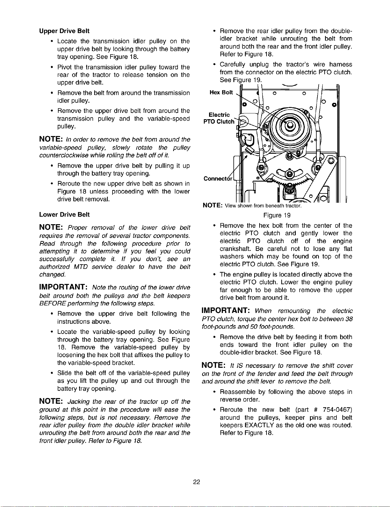
• Carefully unplug the tractor's wire harness
from the connector on the electric PTO clutch.
See Figure 19.
Hex Bolt
O
Electric
PTO Clutch"
NOTE: Viewshownfrombeneathtractor.
Figure 19
• Remove the hex bolt from the center of the
electric PTO clutch and gently lower the
electric PTO clutch off of the engine
crankshaft. Be careful not to lose any flat
washers which may be found on top of the
electric PTO clutch. See Figure 19.
• The engine pulley is located directly above the
electric PTO clutch. Lower the engine pulley
far enough to be able to remove the upper
drive belt from around it.
IMPORTANT: When remounting the electric
PTO clutch, torque the center hex bolt to between 38
foot-pounds and 50 foot-pounds.
• Remove the drive belt by feeding it from both
ends toward the front idler pulley on the
double-idler bracket. See Figure 18.
NOTE: It IS necessary to remove the shift cover
on the front of the fender and feed the belt through
and around the shift lever to remove the belt.
• Reassemble by following the above steps in
reverse order.
• Reroute the new belt (part # 754-0467)
around the pulleys, keeper pins and belt
keepers EXACTLY as the old one was routed.
Refer to Figure 18.
22
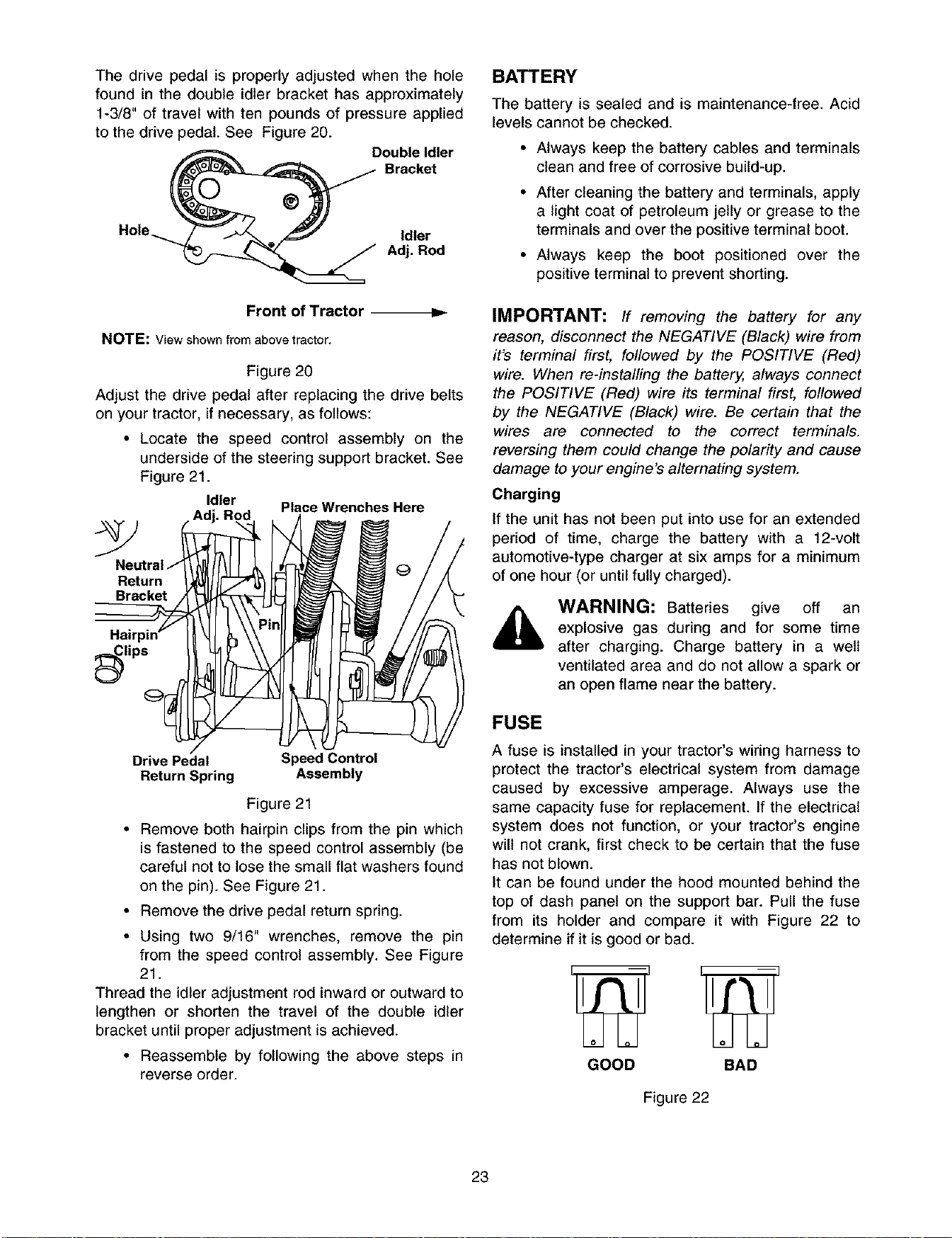
Thedrivepedalis properlyadjustedwhenthe hole
foundinthedoubleidlerbrackethasapproximately
1-3/8"oftravelwithtenpoundsof pressureapplied
tothedrive)edal.SeeFigure20.
")ouble Idler
Bracket
Hole_ Idler
_,.-__ Adj. Rod
Front of Tractor
NOTE: View shown from above tractor.
Figure 20
Adjust the drive pedal after replacing the drive belts
on your tractor, if necessary, as follows:
• Locate the speed control assembly on the
underside of the steering support bracket. See
Figure 21.
Idler Place Wrenches Here
Return
Bracket
lips
Drive Pedal Speed Control
Return Spring Assembly
Figure 21
• Remove both hairpin clips from the pin which
is fastened to the speed control assembly (be
careful not to lose the small flat washers found
on the pin). See Figure 21.
• Remove the drive pedal return spring.
• Using two 9/16" wrenches, remove the pin
from the speed control assembly. See Figure
21.
Thread the idler adjustment rod inward or outward to
lengthen or shorten the travel of the double idler
bracket until proper adjustment is achieved.
• Reassemble by following the above steps in
reverse order.
BATTERY
The battery is sealed and is maintenance-free. Acid
levels cannot be checked.
• Always keep the battery cables and terminals
clean and free of corrosive build-up.
• After cleaning the battery and terminals, apply
a light coat of petroleum jelly or grease to the
terminals and over the positive terminal boot.
• Always keep the boot positioned over the
positive terminal to prevent shorting.
IMPORTANT: If removing the battery for any
reason, disconnect the NEGATIVE (Black) wire from
it's terminal first, followed by the POSITIVE (Red)
wire. When re-installing the battery, always connect
the POSITIVE (Red) wire its terminal first, followed
by the NEGATIVE (Black) wire. Be certain that the
wires are connected to the correct terminals.
reversing them could change the polarity and cause
damage to your engine's alternating system.
Charging
If the unit has not been put into use for an extended
period of time, charge the battery with a 12-volt
automotive-type charger at six amps for a minimum
of one hour (or until fully charged).
WARNING: Batteries give off an
explosive gas during and for some time
after charging. Charge battery in a well
ventilated area and do not allow a spark or
an open flame near the battery.
FUSE
A fuse is installed in your tractor's wiring harness to
protect the tractor's electrical system from damage
caused by excessive amperage. Always use the
same capacity fuse for replacement. If the electrical
system does not function, or your tractor's engine
will not crank, first check to be certain that the fuse
has not blown.
It can be found under the hood mounted behind the
top of dash panel on the support bar. Pull the fuse
from its holder and compare it with Figure 22 to
determine if it is good or bad.
GOOD BAD
Figure 22
23
TIRES
The recommended operating tire pressure is
approximately 10 psi for the rear tires and 14 psi for
the front tires. Refer to the tire sidewall for exact tire
manufacturer's recommended psi. Do not
ovednflate. Uneven tire pressure could cause the
cutting deck to mow unevenly.
CUTTING BLADES
,_, WARNING: Cutting blades are sharp.
Always protect your hands by wearing
heavy leather work gloves to grasp blades.
The blades may be removed for sharpening or
replacement as follows.
• Remove the deck from beneath the tractor,
(refer to DECK REMOVAL earlier in this
section for detailed instructions) then gently
flip the deck over to expose its underside.
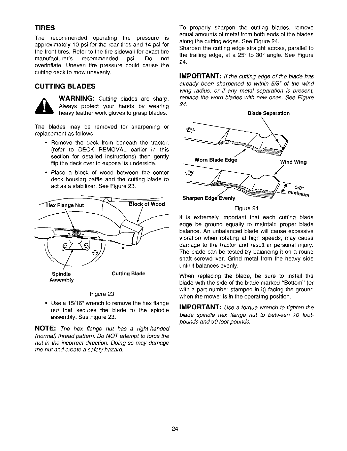
• Place a block of wood between the center
deck housing baffle and the cutting blade to
act as a stabilizer. See Figure 23.
f
Hex Flange Nut
Block of Wood
Spindle Cutting Blade
Assembly
Figure 23
• Use a 15/16" wrench to remove the hex flange
nut that secures the blade to the spindle
assembly. See Figure 23.
NOTE: The hex flange nut has a right-handed
(normal) thread pattern. Do NOT attempt to force the
nut in the incorrect direction. Doing so may damage
the nut and create a safety hazard.
To properly sharpen the cutting blades, remove
equal amounts of metal from both ends of the blades
along the cutting edges. See Figure 24.
Sharpen the cutting edge straight across, parallel to
the trailing edge, at a 25° to 30° angle. See Figure
24.
IMPORTANT: If the cutting edge of the blade has
already been sharpened to within 5/8" of the wind
wing radius, or if any metal separation is present,
replace the worn blades with new ones. See Figure
24.
Blade Separation
Worn Blade Edge Wind Wing
5/8"
Sharpen Edge_venly
Figure 24
It is extremely important that each cutting blade
edge be ground equally to maintain proper blade
balance. An unbalanced blade will cause excessive
vibration when rotating at high speeds, may cause
damage to the tractor and result in personal injury.
The blade can be tested by balancing it on a round
shaft screwdriver. Grind metal from the heavy side
until it balances evenly.
When replacing the blade, be sure to install the
blade with the side of the blade marked "Bottom" (or
with a part number stamped in it) facing the ground
when the mower is in the operating position.
IMPORTANT: Use a torque wrench to tighten the
blade spindle hex flange nut to between 70 foot-
pounds and 90 foot-pounds.
24
SECTION 11: LUBRICATION
_, WARNING: Always stop the engine and disconnect the spark plug wire(s) and ground against the
engine before performing any adjustments, repairs or maintenance.
ENGINE
Lubricate the engine with motor oil as instructed in the separate engine manual packed with your unit.
PIVOT POINTS
Lubricate all pivot points (drive pedal, brake pedal, etc.) at least once a season with light oil.
STEERING SHAFT
Lubricate the steering shaft at least once a season with light oil.
STEERING GEAR
Lubricate the teeth of the steering gear with an all-purpose automotive grease every 25 hours of operation or
once a season. Refer to Figure 13.
LINKAGE
Lubricate all the pivot points on the drive, brake and lift linkage at least once a season with SAE 30 engine oil.
WHEELS
Both the front wheels and the rear wheels should be removed from the axles once a season. Lubricate the
axles and the rims well with an all-purpose automotive grease before re-installing them.
FRONT AXLES
Your tractor is equipped with grease fittings on both ends of the front pivot bar, in front of the both the left and
the right axles. Refer to Figure 12. Lubricate at least once a season with a grease gun.
25

SECTION 12: TROUBLESHOOTING GUIDE
Trouble Corrective Action
Engine will
not crank
Engine
cranks but
will not start
Possible
Cause(s)
Safety switch
button not
depressed.
Battery installed
incorrectly.
Battery is dead
or weak.
Blown fuse
Throttle or choke
not in starting
,osition.
No fuel to the
carburetor.
No spark to
spark plug(s).
There are two safety switches in the starting circuit of your unit: the brake pedal switch
and the seat switch. Make certain the actuator is fully depressing the button on the
brake switch. The operator must be seated on the tractor in order to depress the seat
switch. The PTO knob must be in the disengaged (OFF) positio in order to start the
_ngine, also.
The battery must be installed with negative terminal attached to black ground wire.
Negative terminal is identified at the post by "NEG", "N" or "-". The positive terminal,
identified by "POS", "P" or "+", must be attached to the thick red wire which goes to the
solenoid.
Charge at six amps with a 12-volt automotive-type battery charger for one hour or until
Fullycharged.
Refer to operator's manual for fuse location. Replace fuse with automotive type fuse of
Lheproper amperage. Fuses seldom fail without a reason. The problem must be
corrected. Check for loose connections in the fuse holder. Replace fuse holder if nec-
assary. A dead short may be in the cranking or charging circuit where the insulation
may have rubbed through and exposed the bare wire. Replace the wire or repair with
_lectrician's tape if the wire strands have not been damaged.
Note: Look for a wire pinched between body panels, burned by the exhaust pipe or
muffler or rubbed against a moving part.
Refer to the OPERATION section of this manual for the correct position of the throttle
control and choke for starting.
Gasoline tank empty. Fill.
Fuel line or in-line fuel filter plugged. Remove and clean fuel line. Replace fuel filter
(if so equipped) if necessary.
Spark plug lead disconnected. Connect lead. Using a spark tester, check for spark. If
no spark is present, have engine's magneto serviced by an authorized engine dealer.
Dirty aircleaner. Ifthe air cleaner is dirty, the engine may not start. Refer to the engine manual packed
with your unit.
Engine Engine oil has Check oil level.
smokes been overfilled.
Engine loses Dipstick not seated or broken. Replace defective part.
crankcase Engine breather defective. Replace.
_'acuum.
Excessive Bent blade or Stop engine immediately. Check all pulleys, blade adapters, keys and bolts for
vibration damaged pulley. Lightness and spindle damage. Tighten or replace any loose or damaged parts.
&lways replace damaged blade. Only use original equipment blades.
Mower Engine speed Throttle must be set at full throttle.
won't low.
discharge Speed selection. Use lower ground speed. The slower your ground speed, the better the quality of cut.
grass or Cutting height Raise deck.
Leaves set too low.
uncut strips Blades dull. Sharpen or replace blades (uncut strip problem only).
26

27
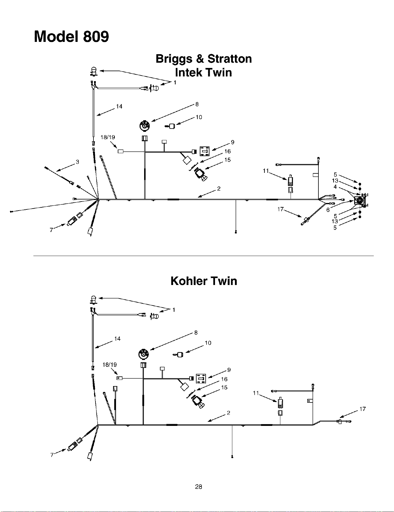
Model 809
Briggs & Stratton
Intek Twin
/14
18/19
11"---._1
Kohler Twin
14
J
18/19
28

REF.
NO.
1
2
3
4
5
6
7
8
9
10
11
12
13
14
15
16
17
18
19
Electrical System
PART
NO.
625-0051
629-0939
629-0941
629-0126
710-0599
712-3006
725-1426
725-1657A
725-1741
725-1743
725-1745
725-1747
736-0222
736-0329
629-0309
725-1752
783-0462
725-3007A
729-0367
725-1381
DESCRIPTION
Bulb/Socket Headlight Assembly
Wiring Harness w/o Ref. 14 (units w/B&S Intek Twin)
Wiring Harness w/o Ref. 14 (units w/Kohler Twin)
Harness Adapter, #18 x 5
Self Tapping Screw, 1/4-20 x .5
Hex Nut, 1/4-20
Solenoid, 12-volt, 100 Amp
Snap Mount Safety Interlock Switch (Brake)
Ignition Switch
Indicator Monitor/Hour Meter
Ignition Key
Safety Plunger Switch (Seat)
External Lock Washer, 1/4
Lock Washer, 1/4
Headlight Harness
Electric PTO Switch
Retainer Bracket
Positive Terminal Cover (Boot)
Fuse Holder
20-amp Fuse
29
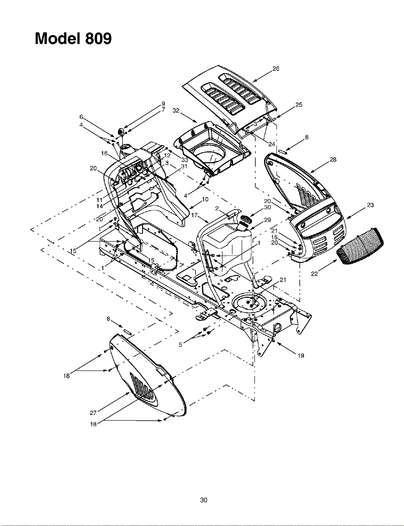
Model 809
J
o
J
A,
3O
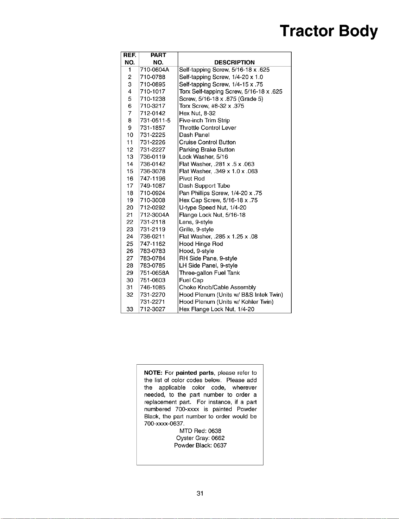
Tractor Body
REF.
NO.
1
2
3
4
5
6
7
8
9
10
11
12
13
14
15
16
17
18
19
20
21
22
23
24
25
26
27
28
29
30
31
32
33
PART
NO.
710-0604A
710-0788
710-0895
710-1017
710-1238
710-3217
712-0142
731-0511-5
731-1857
731-2225
731-2226
731-2227
736-0119
736-0142
736-3078
747-1196
749-1087
710-0924
710-3008
712-0292
712-3004A
731-2118
731-2119
736-0211
747-1162
783-0783
783-0784
783-0785
751-0658A
751-0603
746-1085
731-2270
731-2271
712-3027
DESCRIPTION
Self-tapping Screw, 5/16-18 x .625
Self-tapping Screw, 1/4-20 x 1.0
Self4apping Screw, 1/4-15 x .75
Torx Self-tapping Screw, 5/16-18 x .625
Screw, 5/16-18 x .875 (Grade 5)
Torx Screw, #8-32 x .375
Hex Nut, 8-32
Five-inch Trim Strip
Throttle Control Lever
Dash Panel
Cruise Control Button
Parking Brake Button
Lock Washer, 5/16
Flat Washer, .281 x .5 x .063
Flat Washer, .349 x 1.0 x .063
Pivot Rod
Dash Support Tube
Pan Phillips Screw, 1/4-20 x .75
Hex Cap Screw, 5/16-18 x .75
U-type Speed Nut, 1/4-20
Flange Lock Nut, 5/16-18
Lens, 9-style
Grille, 9-style
Flat Washer, .285 x 1.25 x .08
Hood Hinge Rod
Hood, 9-style
RH Side Pane, 9-style
LH Side Panel, 9-style
Three-gallon Fuel Tank
Fuel Cap
Choke Knob/Cable Assembly
Hood Plenum (Units w/B&S Intek Twin)
Hood Plenum (Units w/Kohler Twin)
Hex Flange Lock Nut, 1/4-20
NOTE: For painted parts, please refer to
the list of color codes below. Please add
the applicable color code, wherever
needed, to the part number to order a
replacement part. For instance, if a part
numbered 700-xxxx is painted Powder
Black, the part number to order would be
700-xxxx-0637.
MTD Red: 0638
Oyster Gray: 0662
Powder Black: 0637
31
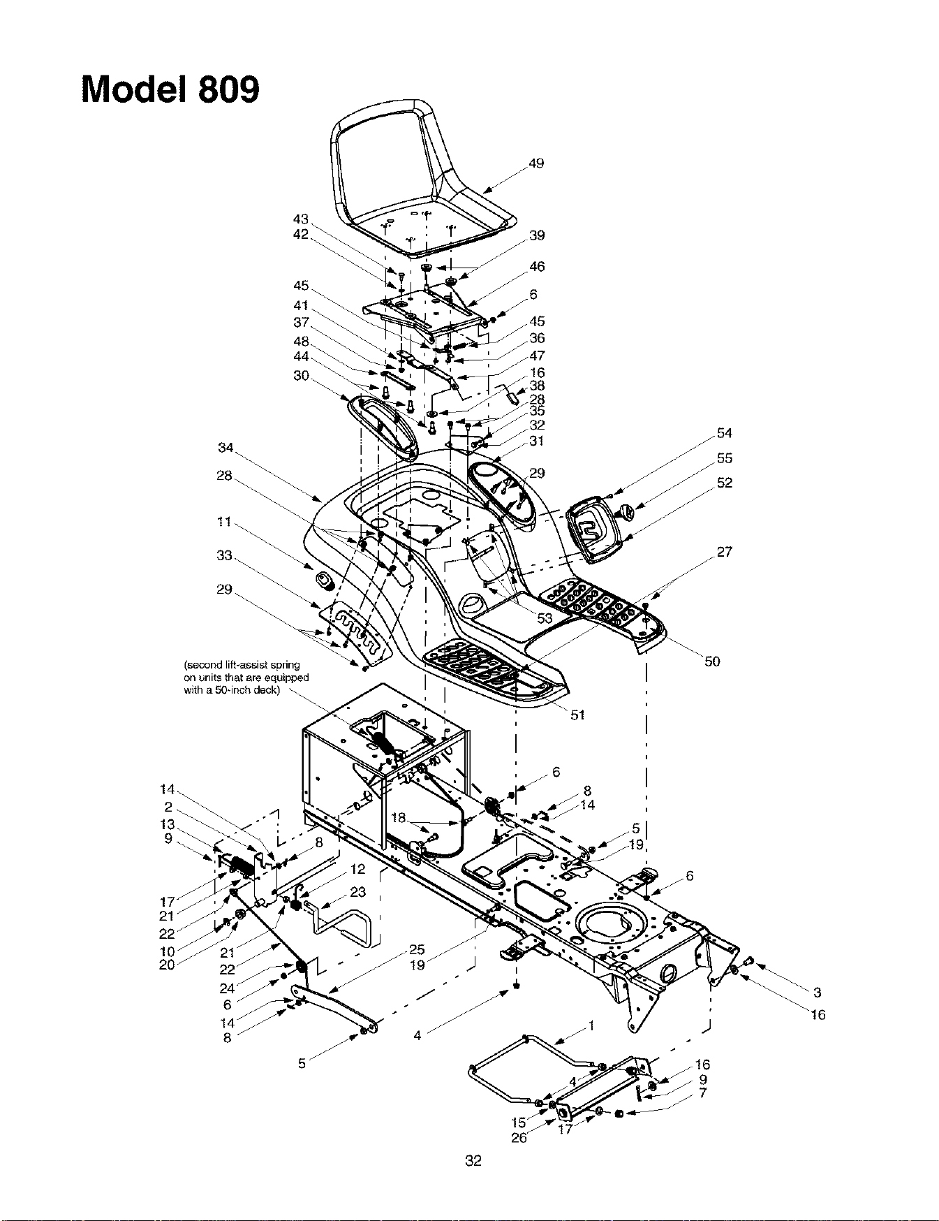
Model 809
: "f*
(second lift-assist spring
on units that are equipped
with a 50qnch deck)
50
32
_3
_16

Lift Assembly
REF.
NO.
1
2
3
4
5
6
7
8
9
10
11
12
13
14
15
16
17
18
19
20
21
22
23
24
25
26
27
28
PART
NO.
747-1130
683-0197
711-0332
712-0206
712-0431
712-3004A
712-3083
714-0104
714-0111
716-0106
720-0311
732-0874
732-0934
736-0275
736-0921
736-3019
736-3084
738-0138
738-0380
741-0225
741-0715
746-0968
747-1111
756-1154
783-0678
783-0720A
710-0260
710-0604
DESCRIPTION
Deck Stabilizer Rod
Lift Shaft Assembly
Clevis Pin, .5 x .78
Hex Nut, 1/2-13
Flange Lock Nut, 3/8-16
Flange Lock Nut, 5/16-18
Hex Nut, 1/2-13
Internal Cotter Pin
Cotter Pin
E-ring
Handle Grip
Torsion Spring
Lift-assist Spring, 1.15 x 5.99
Flat Washer, 5/16
Lock Washer, 1/2
Flat Washer, .31 x 1.062 x. 134
Flat Washer, .51 x 1.12 x .06
Hex Cap Screw, 5/16-18 x .62
Shoulder Screw, .5 x .27, 3/8-16
Hex Flange Bearing
Snap Flange Bearing
Lift Cable, 16.16
Lift Handle
Roller Pulley
Arm Lift
Deck Stabilizer Bracket
Carriage Bolt, 5/16 x .62
Self Tapping Screw, 5/16-18 x .625
REP. PART
NO. NO.
29 710-0895
30 731-1990
31 731-1993
32 738-0155
33 783-0677
34 783-0763A
35 783-0715
36 710-1268
37 712-3027
38 720-0309A
39 731-1989
40 732-0499
41 736-0175
42 736-0204
43 738-0137A
44 738-1007
45 783-0611
46 783-0738
47 783-0739
48 783-0753
49 757-0372
50 735-0657
51 735-0656
726-3046
52 731-2107
53 712-0292
54 710-0924
55 631-0009
DESCRIPTION
Self Tapping Screw, 1/4-15 x .75
Lift Lever Cover
Cover w/Cup Holder
Shoulder Screw, .437 x 1.62
Lift Adjustment Bracket
Fender
Seat Mounting Bracket
Screw, #10-16 x .375
Hex Flange Lock Nut, 1/4-20
Seat Adjuster Grip
Spacer
Compression Spring, .41 x 1.5
Spring Washer, .265 x .562 x .025
Flat Washer, .344 x .62 x .03
Shoulder Screw, .340 x .285,1/4-20
Shoulder Screw, .50 x .50, 3/8-16
Seat Stop
Seat Pivot Bracket
Seat Adjustment Lever
Seat Adjustment Selector
Seat, Radiant Yellow w/Drain Holes
LH Foot Pad
RH Foot Pad
Foot Pad Clips (Not Shown)
Shift Cover
Speed Nut, 1/4-20
Phillips Screw, 1/4-20 x .75
Shift Knob
NOTE: For painted parts, please refer to
the list of color codes below. Please add
the applicable color code, wherever
needed, to the part number to order a
replacement part. For instance, if a part
numbered 700-xxxx is painted Powder
Black, the part number to order would be
700-xxxx-0637.
MTD Red: 0638
Oyster Gray: 0662
Powder Black: 0637
33
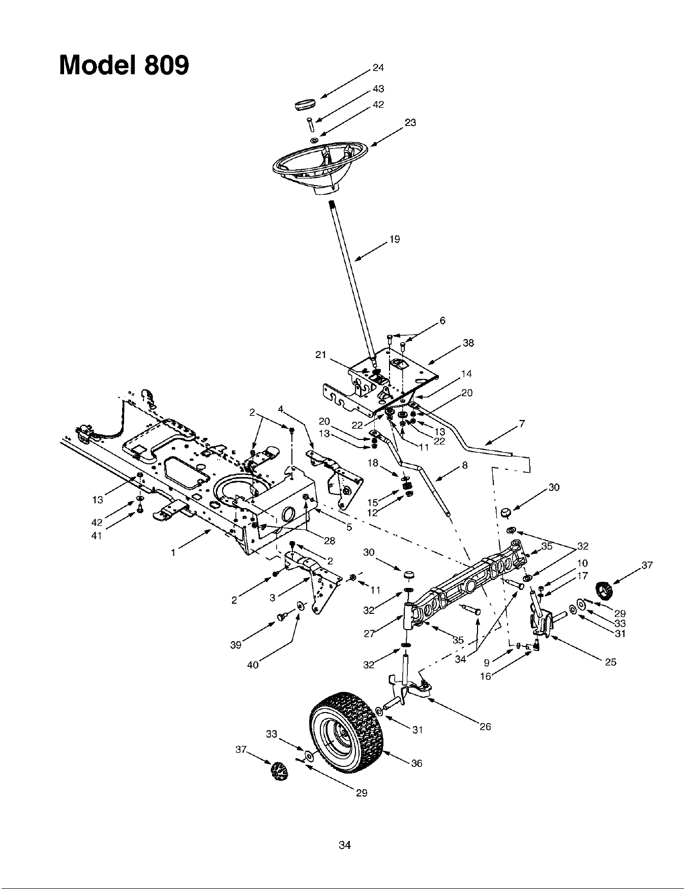
Model 809
31
25
33
34

Steering Assembly
REF.
NO.
1
2
3
4
5
6
7
8
9
10
11
12
13
14
15
16
17
18
19
20
21
22
23
PART
NO.
683-0304
710-0604A
783-0726A
783-0727
783-0728
710-0514
711-1409
711-1408
712-0240
712-0241
712-0431
712-0459
712-3004A
717-1560A
717-1564
723-0448A
736-0169
736-3084
738-1001A
741-0475
741-0656
738-0372
631-0027
DESCRIPTION
Lower Frame Assembly
Self-tapping Screw, 16-18 x .625
RH Pivot Support Bracket
LH Pivot Support Bracket
Pivot Bar Bracket
Hex Cap Screw, 3/8-16 x 1 (Grade 6)
LH Drag Link
RH Drag Link
Jam Nut, 7/16-20 (Grade 2)
Hex Nut, 3/8-24 (Grade 2)
Flange Lock Nut, 3/8-16
Flange Lock Nut, 7/16-20
Flange Lock Nut, 5/16-18
Steering Gear, 11/90 Ratio
Steering Pinion Gear
Ball Joint, 7/16-20
Lock Washer, 3/8
Flat Washer, .51 x 1.12 x .06
Steering Shaft, .625 OD x 24.4
Plastic Bushing, .38 ID
Hex Flange Bearing, 5/8
Shoulder Spacer, .38 ID
Steering Wheel
REF. PART
NO. NO.
24 731-0220
25 638-0017
26 638-0018
27 719-0625B
28 712-0431
29 714-0470
30 726-0341
31 736-0162
32 736-0316
33 736-0285
34 738-1011
35 737-3000
36 634-0183
634-0182
734-0255
734-1727
37 734-2290
38 783-0653A
39 738-0143
40 736-0331
41 738-0140
42 736-0242
43 710-0643
DESCRIPTION
Steering Wheel Cap
LH Axle Assembly, .750 Diameter
RH Axle Assembly, .750 Diameter
Cast Iron Pivot Bar
Flange Lock Nut, 3/8-16
Cotter Pin
Push Cap, .750
Flat Washer, .64 x 1.0 x .12
Flat Washer, .78 x 1.59 x .06
Flat Washer, .635 x 1.589 x .06
Shoulder Screw, .5 x 2.2, 3/8-16
Lube Fitting, 3/16
Wheel Assembly Complete, 16 x 6.5 x 8
Rim Only
Air Valve (Not Shown)
Tire Only, Square Shoulder
Hub Cap
Steering Support Bracket
Shoulder Screw, 3/8-16
Bell Washer, .39 x 1.13 x .062
Shoulder Screw, .435 x .178, 5/16 x .56
Bell Washer, .34 x .872
Hex Bolt, 5/16-18 X 1
NNOTE: For painted parts, please refer
to the list of color codes below. Please
add the applicable color code, wherever
needed, to the part number to order a
replacement part. For instance, if a part
numbered 700-xxxx is painted Powder
Black, the part number to order would be
700-xxxx-0637.
MTD Red: 0638
Oyster Gray: 0662
Powder Black: 0637
35
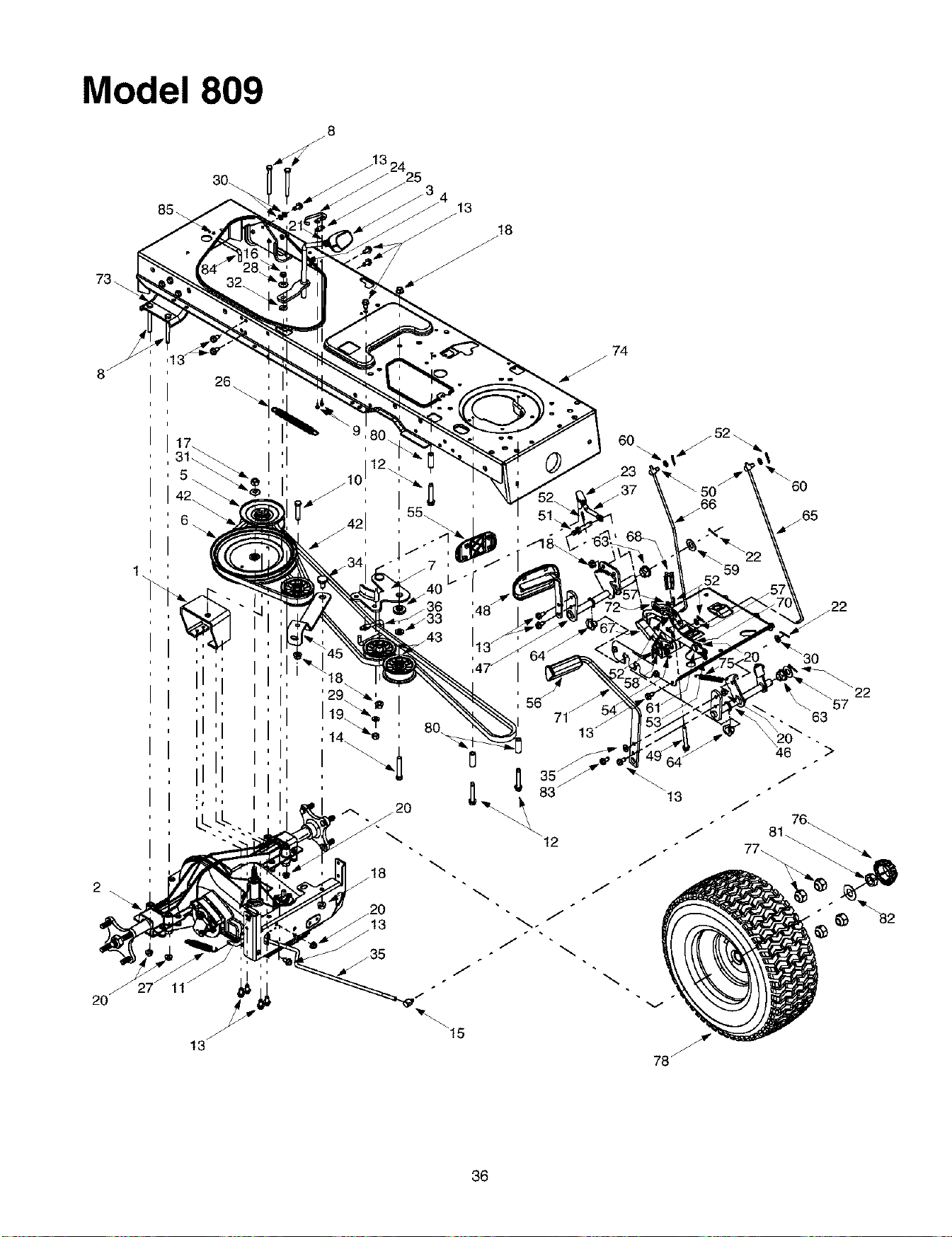
Model 809
j8
73 \
8 j
26
74
2O
13
v
78_
3O
63
46 >
36

Drive System
REF.
NO.
1
2
3
4
5
6
7
8
9
10
11
12
13
14
15
16
17
18
19
20
21
22
23
24
25
26
27
28
29
30
31
32
33
34
35
36
37
38
39
40
41
42
43
44
PART
NO.
618-0375
618-0376
631-0009
647-0037
656-0050
656-0051
683-0251
710-0189
710-0227
710-0347
710-0528
710-0778
710-0604A
710-3011
711-0677
712-0181
712-0378
712-0431
712-0798
712-3004A
712-3008
714-0111
723-3018
725-1713
726-0320
732-0384
732-0716
736-0105
736-0169
736-0275
736-0407
736-0642
736-3010
738-0322
747-1122
747-1123A
747-1127
710-1026
747-1185
748-0416
754-0467
754-0468
756-0981
783-0667
DESCRIPTION
Variable-speed Bracket Assembly
Two-speed Transmission Assembly
Shfter Knob
Shift Lever
Variable-speed Pulley Assembly
Transmission Pulley, 8.5 x .5 - 36
Double-idler Bracket
Hex Cap Screw, 5/16-18 x 3
Self Tapping Screw, #8-18 x .5
Hex Cap Screw, 3/8-16 x 1.75
Hex Cap Scerw, 5/16-18 x 1.25
Self-tapping Screw, 1/4-20 x 1.5
Self Tapping Screw, 5/16-18 x .625
Hex Cap Screw, 3/8-16 x 2.25
Ferrule, 5/16 x .312 Dia.
Hex Jam Nut, 3/8-16
Hex Nut, 7/16-20
Flange Lock Nut, 3/8-16
Hex Nut, 3/8-16
Flange Lock Nut, 5/16-18
Hex Jam Nut, 3/8-16
Cotter Pin
Ball Joint, 3/8-24
Spring Switch
Insulator Nut Plate
Extension Spring, .62 Dia. x 6.12
Extension Spring, .59 OD x 4.0
Bell Washer, .401 x .870 x .063
Lock Washer, 3/8
Flat Washer, 5/16
Bell Washer, .45 x 1.0 x .062
Flat Washer, .44 x .75 x .06
Flat Washer, .407 x .812 x. 135
Shoulder Screw, .625 Dia. x .21
Brake Rod
Belt Guard
Idler Adjustment Rod, 3/8
Self-tapping Screw, 1/4-20 x 1.75
Transmission Belt Guard Rod
Shoulder Spacer, .380 ID
Variable-speed Belt
Drive Belt
Flat Idler, 2.75 OD
Transmission Torque Bracket
REP.
NO.
45
46
47
48
49
5O
51
52
53
54
55
56
57
58
59
60
61
62
63
64
65
66
67
68
69
70
71
72
73
74
75
76
77
78
79
80
81
82
83
84
85
PART
NO.
783-0669
647-0031
647-0032
683-0266
710-1135
711-0736
711-1363
714-0104
732-0437
732-0955
735-0662
735-3049
736-0140
736-0142
736-0187
736-0204
738-0155
738-0507B
741-0225
741-3065A
747-1137
747-1138
748-0413
748-0415A
783-0653B
783-0732
783-0773
783-0780A
783-0693
683-0304
732-0963
731-2290
712-3050
634-0202
634-3178
734-0255
734-1728
750-0768
750-0566
712-3026
736-0316
710-1260A
747-1185
710-0599
DESCRIPTION
Idler Bracket
Brake Control Shaft Assembly
Speed Control Shaft Assembly
Drive Pedal Assembly
Self Tapping Screw, 5/16-18 x 2.5
Ferrule, 1/4-20
Pin, 3/8-16 x 2.43
Cotter Pin
Compression Spring, .34 OD x 1.0
Extension Spring, .50D x 1.41
Drive Pedal Pad
Brake Pedal Pad
Flat Washer, .281 x .5 x .0625
Flat Washer, 9/32 x 1/2 x 1/16
Flat Washer, .64 x 1.24 x .06
Flat Washer, .344 x .062 x .03
Shoulder Screw, .437 x 1.62
Shoulder Screw, .5 x .434
Hex Flange Bearing
Split Hex Flange Bearing
Cruise Control Rod
Brake Lock Control Rod
Cruise Latch
Spacer, 5/16 x 1.54
Steering Support Bracket
Drive Lockout Bracket
Brake Pedal
Neutral Return Bracket
Axle Bracket
Lower Frame Assembly
Extension Spring, .50D x 6.37
Hub Cap
Lug Nut, 7/16-14
Wheel Assembly Complete, 23 x 9.5 x 12
Rim Only
Air Valve
Tire Only, Square Shoulder
Split Spacer, .25 x .37 x 1.32
Spacer, .372 x .26 x 1.03
Jam Nut, 3/4-16
Flat Washer, .78 x 1.59 x .06
Hex Screw, 5/16-18 x .75
Transmission Belt Guard Rod
Self Tapping Screw, I/4-20 x .5
37
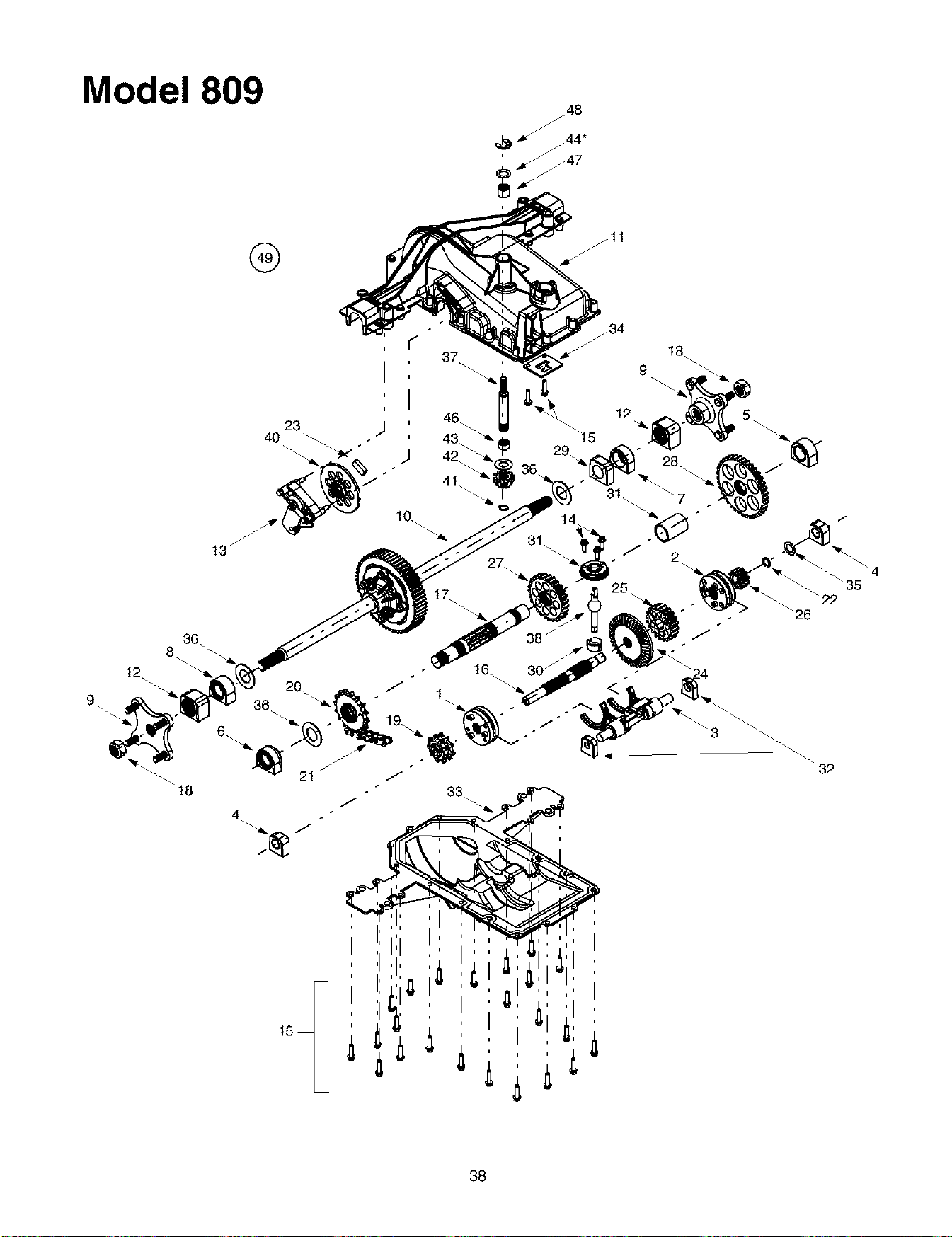
Model 809
®
36
8..
12
18
r"
37
12
\22
\26
32
i
,ii:i
38

REE PART
NO. NO.
1 618-0225
2 618-0226
3 618-0227A
4 618-0284
5 618-0285
6 618-0286
7 618-0287
8 618-0302
9 618-0365
10 618-0368
11 719-0379A
12 641-0002A
13 661-0012
14 710-0642
15 710-0788
16 711-1051A
17 711-1216
18 712-1329
19 713-0446
20 713-0447
21 713-0448
22 716-0131
23 717-0678
24 717-1438
25 717-1439
26 717-1440
27 717-1441
28 717-1442
29 718-0500
30 718-0504
31 718-0505
32 718-0537
33 719-0385
34 718-0540
35 736-0337
36 736-3046A
37 711-1235
38 747-1140
39 750-1033A
40 761-0215
41 716-0114
42 717-1463
43 736-0335
44 736-0336
736-0337
736-0349
46 741-0335
47 741-0696
48 716-0231
49 618-0376
Two-speed Transmission
DESCRIPTION
Reverse Collar Assembly
Hi-Lo Collar Assembly
Shift Fork Assembly
Detent Block Assembly
Output Bearing Block Assembly
Output Seal Bearing Block Assembly
Inboard Sealed Axle Block Assembly
Inboard Sealed Axle Block Assembly
Wheel Hub Assembly
Differential Axle Assembly
Upper Housing
Axle Bearing Block Assembly
Brake Assembly
Self-tapping Screw, 1/4-20 x .75
Self-tapping Screw, 1/4-20 x 1.0
Drive Shaft
Output Shaft
Nut, 3/4-16
9-tooth Sprocket
16-tooth Sprocket
22-1ink Chain, .625
External Snap Ring
Brake Pad
41-tooth Bevel Gear
20-tooth Spur Gear
10-tooth Spur Gear
27-tooth Spur Gear
37-tooth Spur Gear
Inner Axle Bearing Block
Shifter Insert
Shifter Cover
Shifter Bearing Block
Lower Housing
Lockout Plate
Flat Washer, 5/8 x 1.0
Flat Washer, 1.01 x 1.86 x .060
Input Shaft
Shift Lever
Spacer, 1.13 x 1.38 x 1.968
Disc Brake
Retaining Ring, .56
13-tooth Bevel Gear
Flat Washer
Flat Washer, 5/8 x 1.0 x .030*
Flat Washer, 5/8 x 1.0 x ..040*
Fair Washer,5/8 x 1.0 x .020*
Needle Bearing
Needle Bearing
E-ring, .75
Transmisssion Assembly Complete
NOTE: Transmission has a grease capacity of 32 oz. Order part number 737-0148.
NOTE: Upon reassembling transmission input shaft for any reason, refill its cavity
with approximately 2/3 oz. of grease. Order part number 737-0289.
*Use appropriate flat washer in this application allowing no more than .012 maximum end play
39
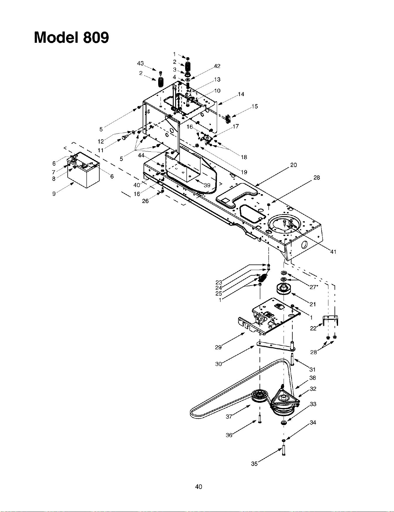
Model 809
43
2
16_
26
28
I
I
38
40

Power Take-off Systems
RED PART
NO. NO.
1 712-0431
2 732-0735
3 783-0733
4 732-0956
5 710-0604A
6 710-0751
7 712-0271
8 712-3044
9 725-1706
10 738-1014
11 738-1020
12 736-0407
13 723-0444
14 783-1033
15 725-1747
16 736-0222
17 725-1426
18 710-0599
19 712-0459
20 683-0304
21 756-0639A
22 783-1003
23 712-3010
DESCRIPTION
Flange Lock Nut, 3/8-16
Compression Spring, 1.318 x 2.37
Spacer Cup, 1.50D
Compression Spring, .66 OD x 1.5
Self-tapping Screw, 5/16-18 x .625
Hex Cap Screw, 1/4-20 x .62
Hex Sems Nut, 1/4-20
Wing Nut, 1/4-20
12-volt Battery, 270 CCA
Shoulder Screw, .5 x 1.25, 3/8-16
Shoulder Screw, .625 x .5, 7/16-20
Bell Washer, .45 x 1.0 x .062
Battery Strap
Hitch Plate
Safety Interlock Plunger Switch
Lock Washer, 1/4
Solenoid, 12-Volt, 100 Amp
Self-tapping Screw, 1/4-20 x .5
Flange Lock Nut, 7/16-20
Lower Frame Assembly
Engine Pulley, 3.56 OD
Electric Clutch Anti-rotation bracket
Hex Nut, 5/16-18
REF. PART
NO. NO.
24 710-3180
25 732-0978
26 710-0642
27 736-0277
28 712-3004A
29 783-0683B
30 883-0294
31 738-3056
32 717-1709
33 738--0785
34 736-0171
35 710-3157
710-0561
36 710-3011
37 756-0627
38 754-0476
754-0475
39 783-0349
40 736-0119
41 710-3025
42 736-0105
43 710-0650
44 712-3006
DESCRIPTION
Hex Cap Screw, 5/16-18 x 1.75 (Grade 5)
Extension Spring, 1.20D x 3.638
Self-tapping Screw, 1/4-20 x .750
Flat Washer, 1.031 x 1.62 x .095*
Flange Lock Nut, 5/16-18
Steering Support Bracket
Idler Bracket Assembly
Shoulder Screw, 1/2 Diameter x 2.5
Electric PTO Clutch
Shoulder Spacer, 1.38 x .445 x .36
Lock Washer, 7/16
Hex Cap Screw, 7/16-20 x 3.25 (Grade 5)
Hex Cap Screw, 7/16-20 x 2.5 (Grade 5)*
Hex Cap Screw, 3/8-16 x 2.25 (Grade 5)
Flat idler Pulley, 3.50D
PTO Belt (46-inch Decks)
PTO Belt (50-inch Decks)
Battery Tray
Lock Washer, 5/16
Hex Cap Screw, 5/16-18 x .625
Bell Washer, .401 x .870 x .063
Self-tapping Screw, 5/16-18 x .875
Hex Nut, 1/4-20
*Found on units equipped with a Kohler engine ONLY.
NOTE: For painted parts, please refer to
the list of color codes below. Please add
the applicable color code, wherever
needed, to the part number to order a
replacement part. For instance, if a part
numbered 700-xxxx is painted Powder
Black, the part number to order would be
700-xxxx-0637.
MTD Red: 0638
Oyster Gray: 0662
Powder Black: 0637
41
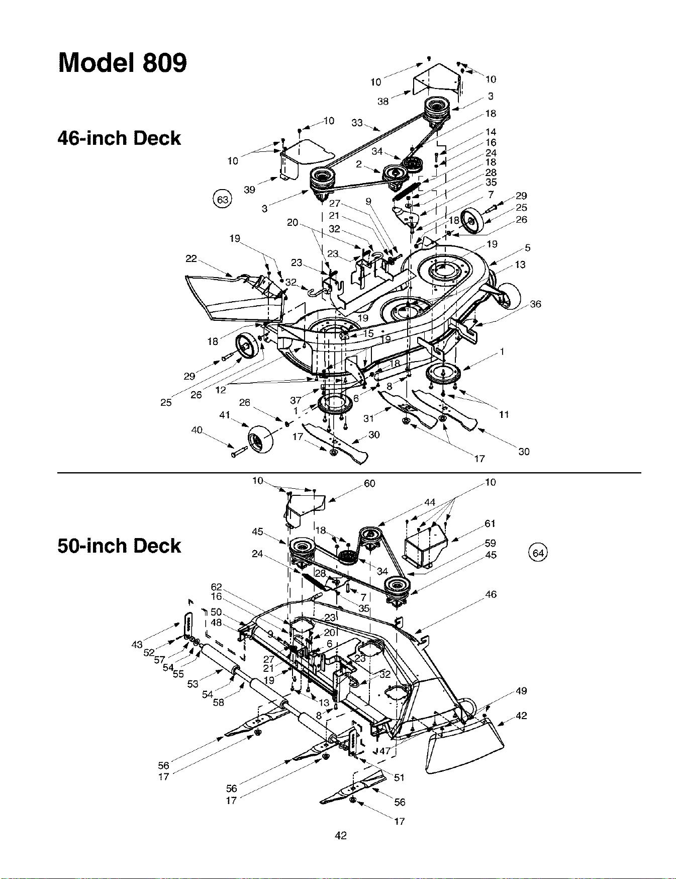
Model 809
46-inch Deck
29 j
25
50-inch Deck
26
40_
11
3O
,_6o
G
43j
42

Cutting Decks
REF.
NO.
1
2
3
4
5
6
7
8
9
10
11
12
13
14
15
16
17
18
19
20
21
22
23
24
25
26
27
28
29
30
31
PART
NO.
17982
618-0240
756-0959
618-0241
756-0603
683-0254
683-0199B
710-0167
710-0347
710-0514
710-0528
710-0699
710-0650
710-0751
710-1260A
712-0106
16606
712-0291
712-0417A
712-0431
712-3027
714-0104
717-1563A
731-1032B
732-0306
732-0594A
734-0973
736-0105
736-0119
738-0347
738-0373
742-0611
742-0612
REF. PART
DESCRIPTION NO. NO.
Reinforcement Spindle Plate 32 747-1116
Center Spindle Assembly, 5 Dia. 33 754-0474
Pulley Only 34 756-0627
Double Pulley Spindle Assembly 35 783-0139
Double Pulley Only 36 783-0141
Deck Adjustment Bracket w/Weld Nut 37 783-0142
46-inch Deck Shell 38 783-0747
Carriage Screw, 1/4-20 x .5 39 783-0805A
Hex Cap Screw, 3/8-16 x 1.75 40 738-3056
Hex Cap Screw, 3/8-16 x 1.0 41 734-30586
Hex Cap Screw, 5/16-18 x 1.25 42 12649
Self Tapping Screw, I/4-20 x .5 43 12650
Self Tapping Screw, 5/16-18 x .875 44 618-0268
Hex Cap Screw, 1/4-20 x .62 45 618-0269
Self Tapping Screw, 5/16-18 x .75 46 683-0196
Hex Cap Screw, 1/4-20 x 1.25 (Grade 5) 47 710-0260
Retainer Hook 48 711-0332
Center Lock Nut, 1/4-20 49 712-3004A
Hex Flange Nut, 5/8-18 50 714-0145
Flange Lock Nut, 3/8-16 51 715-0108
Hex Flange Lock Nut, 1/4-20 52 715-0246
Internal Cotter Pin, .072 x 1.12 53 731-0335
Deck Adjustment Gear 54 736-0316
Side Discharge Chute Assembly 55 738-0295
Compression Spring, .406 x .531 x 1.75 56 742-0623
Extension Spring, .91 x7.33 57 750-0212
Deck Wheel, 5 x 1.38 58 750-0288
Bell Washer, .401 x .87 x .063 59 754-0291A
Lock Washer, 5/16 60 783-0746
Shoulder Spacer, .625 x.169 61 783-0793
Shoulder Spacer, .498 x 1.53 62 710-3288
Three-in-one Blade, Star Center, 16.28 63 753-0875
Three-in-one Blade, Star Center, 14.88 64 753-0877
DESCRIPTION
Deck Release Pin
Deck Belt
Flat idler Pulley, 3.50D
Idler Bracket
Center Deck Skirt
RH Deck Skirt
LH Belt Cover
RH Belt Cover
Shoulder Screw, .5 x 2.5
Deck Wheel, 5
Chute Guard
Height Adjustment Bracket
Center Spindle Assembly, 5 Dia.
Double Pulley Spindle Assembly
50-inch Deck Shell
Carriage Bolt, 5/16-18 x .62
Clevis Pin, .50 Dia. x .78
Hex Flange Lock Nut, 5/16-18 (Grade 5)
Click Pin, .092 x 1.64
Spring Pin, 1/4 Dia. x 1
Spring Pin, 3/16 x 1.25
Deck Roller
Flat Washer, .78 x 1.59 x .06
Deck Roller Shaft, .75 Dia. x 47.12
Blade, Star Center, 17.3
Spacer, .752 x 1.0 x .53
Spacer, .82 x 1.0 x 5.75
Deck Belt
Belt Cover, L.H.
Belt Cover, R.H.
Hex Cap Screw, 1/4-20 x 1.62
46-inch Deck Assembly Complete
50-inch Deck Assembly Complete
NOTE: For painted parts, please refer to
the list of color codes below. Please add
the applicable color code, wherever
needed, to the part number to order a
replacement part. For instance, if a part
numbered 700-xxxx is painted Powder
Black, the part number 1o order would be
700-xxxx-0637.
MTD Red: 0638
Oyster Gray: 0662
Powder Black: 0637
43
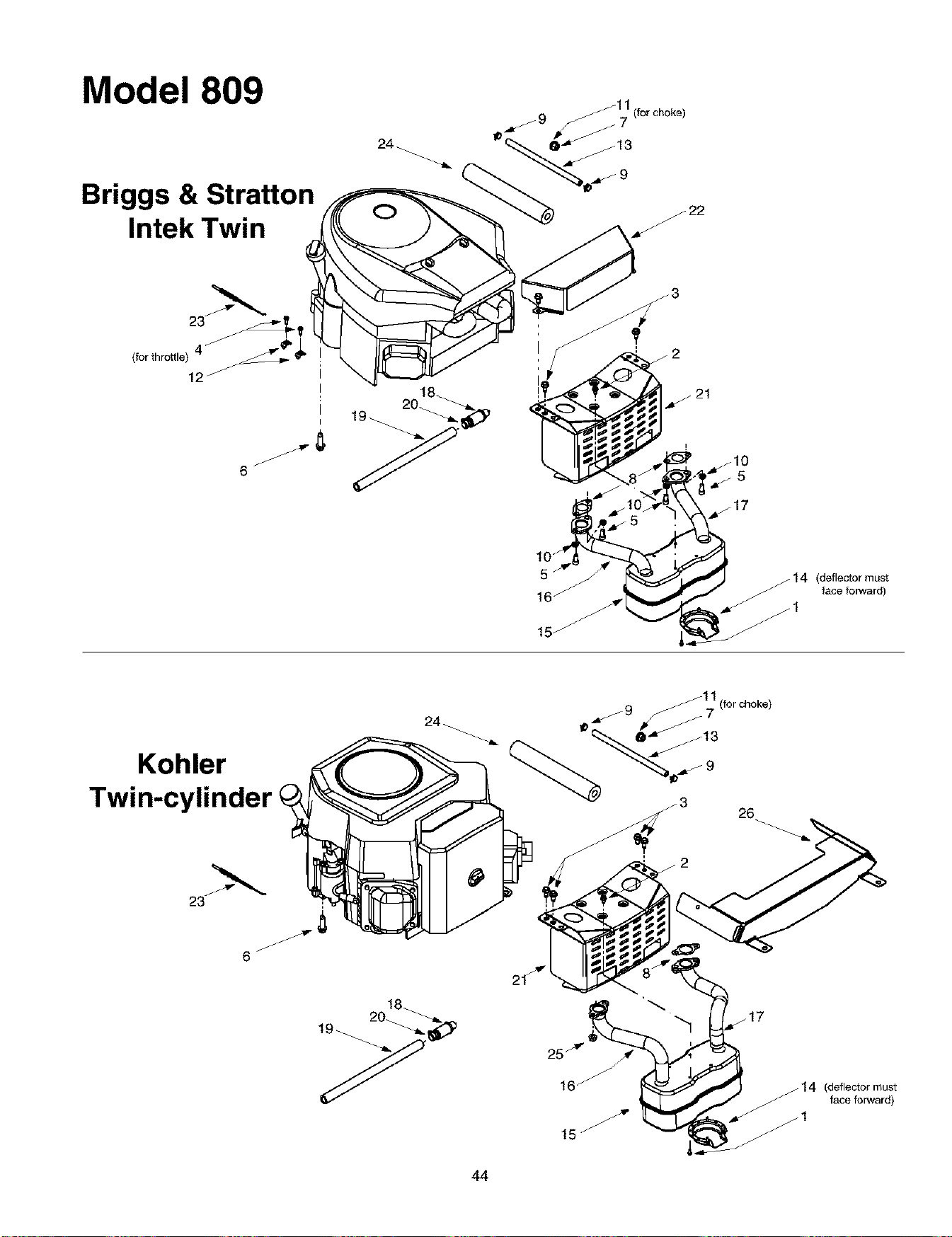
Model 809
Briggs & Stratton
Intek Twin
(,orthrott,e)__
12 i
I
I
I
6 j
18
20_
(deflector must
face forward)
Kohler
Twin-cylinder
44
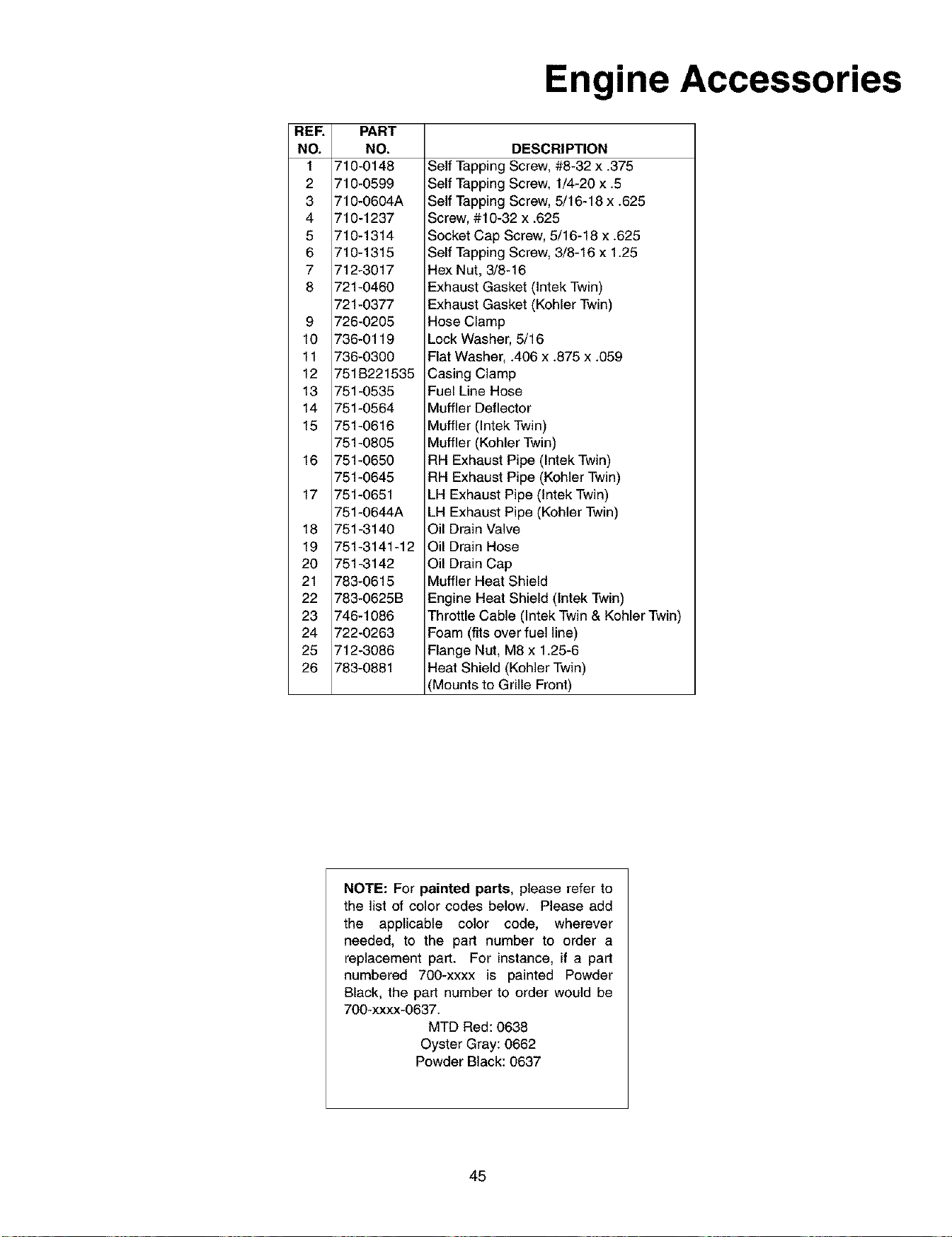
REF.
NO.
1
2
3
4
5
6
7
8
9
10
11
12
13
14
15
16
17
18
19
20
21
22
23
24
25
26
Engine Accessories
PART
NO.
710-0148
710-0599
710-0604A
710-1237
710-1314
710-1315
712-3017
721-0460
721-0377
726-0205
736-0119
736-0300
751B221535
751-0535
751-0564
751-0616
751-0805
751-0650
751-0645
751-0651
751-0644A
751-3140
751-3141-12
751-3142
783-0615
783-0625B
746-1086
722-0263
712-3086
783-0881
DESCRIPTION
Self Tapping Screw, #8-32 x .375
Self Tapping Screw, 1/4-20 x .5
Self Tapping Screw, 5/16-18 x .625
Screw, #10-32 x .625
Socket Cap Screw, 5/16-18 x .625
Self Tapping Screw, 3/8-16 x 1.25
Hex Nut, 3/8-16
Exhaust Gasket (Intek Twin)
Exhaust Gasket (Kohler Twin)
Hose Clamp
Lock Washer, 5/16
Flat Washer, .406 x .875 x .059
Casing Clamp
Fuel Line Hose
Muffler Deflector
Muffler (Intek Twin)
Muffler (Kohler Twin)
RH Exhaust Pipe (Intek Twin)
RH Exhaust Pipe (Kohler Twin)
LH Exhaust Pipe (Intek Twin)
LH Exhaust Pipe (Kohler Twin)
Oil Drain Valve
Oil Drain Hose
Oil Drain Cap
Muffler Heat Shield
Engine Heat Shield (tntek Twin)
Throttle Cable (Intek Twin & Kohler Twin)
Foam (fits over fuel line)
Flange Nut, M8 x 1.25-6
Heat Shield (Kohler Twin)
(Mounts to Grille Front)
NOTE: For painted parts, please refer to
the list of color codes below. Please add
the applicable color code, wherever
needed, to the part number to order a
replacement part. For instance, if a part
numbered 700-xxxx is painted Powder
Black, the part number to order would be
700-xxxx-0637.
MTD Red: 0638
Oyster Gray: 0662
Powder Black: 0637
45
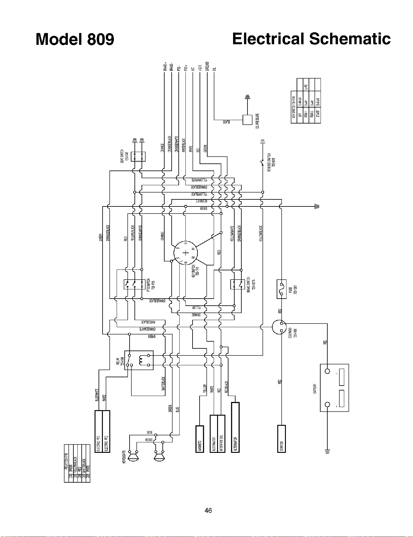
Model 809 Electrical Schematic
Illl
46

Notes
47

MANUFACTURER'S LIMITED WARRANTY FOR:
O TRO_ BILT'__
The limited warranty set forth below is given by MTD
PRODUCTS INC ("MTD") with respect to new merchandise
purchased and used in the United States, its possessions
and territories.
MTD warrants this product against defects in material and
workmanship for a period of two (2) years commencing on
the date of original purchase and will, at its option, repair or
replace, free of charge, any part found to be defective in
material or workmanship. This limited warranty shall only
apply if this product has been operated and maintained in
accordance with the Operator's Manual furnished with the
product, and has not been subject to misuse, abuse, com-
mercial use, neglect, accident, improper maintenance,
alteration, vandalism, theft, fire, water or damage because
of other peril or natural disaster. Damage resulting from the
installation or use of any accessory or attachment not
approved by MTD Products Inc. for use with the product(s)
covered by this manual will void your warranty as to any
resulting damages.
Normal wear parts or components thereof are subject to
separate terms as follows: All normal wear part or compo-
nent failures will be covered on the product for a period of
90 days regardless of cause. After 90 days, but within the
two year period, normal wear part failures will be covered
ONLY IF caused by defects in material or workmanship of
OTHER component parts. Normal wear parts and compo-
nents include, but are not limited to, belts, blades, blade
adapters, grass bags, rider deck wheels, seats, snow
thrower skid shoes, shave plates and tires. Batteries are
covered by a 90-day limited replacement warranty.
HOW TO OBTAIN SERVICE: Warranty service is available,
WITH PROOF OF PURCHASE THROUGH YOUR LOCAL
AUTHORIZED SERVICE DEALER. To locate the dealer in
your area, please check for a listing in the Yellow Pages or
contact the Customer Service Department of MTD PROD-
UCTS INC by calling 1-800-800-7310 or writing to P.O. Box
368022, Cleveland, Ohio 44136-9722.
This limited warranty does not provide coverage in the
following cases:
a. The engine or component parts thereof. These items
carry a separate manufacturer's warranty. Please refer
to the applicable manufacturer's warranty on these
items.
b. Log splitter pumps, valves and cylinders have a sepa-
rate one year warranty.
c. Routine maintenance items such as lubricants, filters,
blade sharpening and tune-ups, or adjustments such
as brake adjustments, clutch adjustments or deck
adjustments; and normal deterioration of the exterior
finish due to use or exposure.
d. MTD does not extend any warranty for products sold
or exported outside of the United States of America,
its possessions and territories, except those sold
through MTD's authorized channels of export distribu-
tion.
NO implied warranty, including any implied warranty of
merchantability or fitness for a particular purpose,
applies after the applicable period of express written
warranty above as to the parts as identified. No other
express warranty or guaranty, whether written or oral,
except as mentioned above, given by any person or
entity, including a dealer or retailer, with respect to any
product shall bind MTD. During the period of the War-
ranty, the exclusive remedy is repair or replacement of
the product as set forth above. (Some states do not
allow limitations on how long an implied warranty lasts, so
the above limitation may not apply to you.)
The provisions as set forth in this Warranty provide the
sole and exclusive remedy arising from the sales. MTD
shall not be liable for incidental or consequential loss
or damages including, without limitation, expenses
incurred for substitute or replacement lawn care ser-
vices, for transportation or for related expenses, or for
rental expenses to temporarily replace a warranted
product. (Some states do not allow the exclusion or limita-
tion of incidental or consequential damages, so the above
exclusion or limitation may not apply to you.)
In no event shall recovery of any kind be greater than the
amount of the purchase price of the product sold. Alteration
of the safety features of the product shah void this War-
ranty. You assume the risk and liability for loss, damage, or
injury to you and your property and/or to others and their
property arising out of the use or misuse or inability to use
the product.
This limited warranty shall not extend to anyone other than
the original purchaser, original lessee or the person for
whom it was purchased as a gift.
How State Law Relates to this Warranty: This limited
warranty gives you specific legal rights, and you may also
have other rights which vary from state to state.