Loading ...
Loading ...
Loading ...
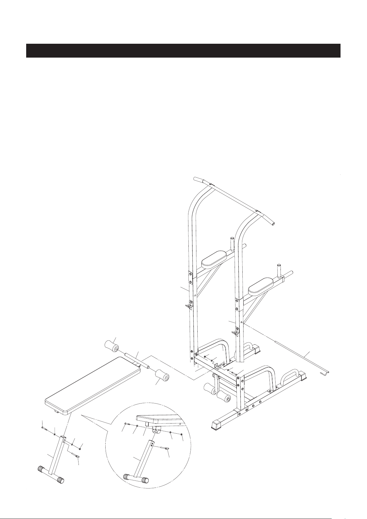
ASSEMBLY INSTRUCTIONS
STEP 9
Refer to the detail view and illustration below. Attach the BENCH SUPPORT(15) to the BENCH FRAME
(14) with HEX BOLT(M8x1.25x55mm)(34), WASHERS(M8)(37), and NYLOCK NUT(M8x1.25)(39). Lock
the BENCH SUPPORT(15) in position by inserting the PULL PIN(16) through one of the adjustment
holes in the U bracket under the BENCH FRAME(14) and the holes in the BENCH SUPPORT(15).
STEP 10
Attach the BENCH FRAME(14) to the UPRIGHT CROSS BAR(6) with HEX BOLT(M8x1.25x55mm)(34),
WASHERS(M8)(37), and NYLOCK NUT(M8x1.25)(39). Slide the FOAM PADS(19) onto both sides of
the BENCH FRAME(14). Store the LOCKING BAR(11) by inserting the LOCKING BAR(11) through the
holes in both of the UPRIGHTS(3).
11
6
34
37
37
39
19
19
16
34
37
37
39
37
39
37
16
34
15
14
14
15
11
3
3
Loading ...
Loading ...
Loading ...