Loading ...
Loading ...
Loading ...
11
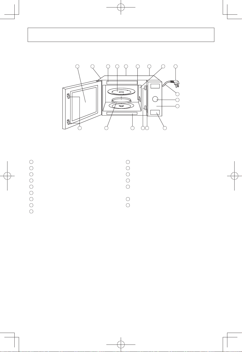
Oven Components Diagram
1
External Air Vent
2
Internal Air Vent
3
Door Safety Lock System
4
Exhaust Air Vent
5
Control Panel
6
Identification Plate
7
Glass Tray
8
Roller Ring
9
Heat/Vapor Barrier Film
(do not remove)
10
Waveguide Cover
(do not remove)
11
Door Release Button
12
Warning Label
13
Function Label
14
Time/Weight and Sensor Menu
Dial
15
Power Supply Cord
16
Power Supply Plug
1
4
5
7
12
3
12
9
2
10
15
14
8
13
3
6
11
16
Note
: The illustration is for reference only.
F0003BP43CP_En.indd 11 2017/12/20 9:19:58
Loading ...
Loading ...
Loading ...