
OWNER’S MANUAL
MANUALE UTENTE
MU 7100EN MKII
DXT 7000EN VOICE ALARM SYSTEM AMPLIFIED MASTER UNIT


3
CONTENTS
ENGLISH
CONTENTS ..................................................................................................................................................................................... 3
SAFETY PRECAUTIONS AND GENERAL INFORMATION .................................................................................................................... 4
DESCRIPTION ................................................................................................................................................................................. 6
FRONT PANEL ................................................................................................................................................................................ 7
REAR PANEL .................................................................................................................................................................................. 8
OTHER SYSTEM COMPONENTS..................................................................................................................................................... 10
MU 7100EN MKII OPERATION AND USE ....................................................................................................................................... 12
MAINTENANCE ............................................................................................................................................................................ 22
ITALIANO
AVVERTENZE PER LA SICUREZZA ................................................................................................................................................. 23
DESCRIZIONE ............................................................................................................................................................................... 26
PANNELLO FRONTALE .................................................................................................................................................................. 27
PANNELLO POSTERIORE ............................................................................................................................................................... 28
ALTRI COMPONENTI DEL SISTEMA ............................................................................................................................................... 30
MU 7100EN MKII – FUNZIONAMENTO ED USO ............................................................................................................................ 32
MANUTENZIONE .......................................................................................................................................................................... 42
DIMENSIONS ................................................................................................................................................................................ 43
SPECIFICATIONS ........................................................................................................................................................................... 44
4
SAFETY PRECAUTIONS AND GENERAL INFORMATION
The symbols used in this document give notice of important
operating instructions and warnings which must be strictly
followed.
CAUTION
Important operating
instructions: explains hazards
that could damage a product,
including data loss.
WARNING
Important advice concerning the
use of dangerous voltages and
the potential risk of electric
shock, personal injury or death.
IMPORTANT
NOTES
Helpful and relevant
information about the topic.
SUPPORTS,
TROLLEYS
AND CARTS
Information about the use of
supports, trolleys and carts.
Reminds to move with extreme
caution and never tilt.
WASTE
DISPOSAL
This symbol indicates that this
product should not be disposed
with your household waste,
according to the WEEE directive
(2012/19/EU) and your national
law.
IMPORTANT NOTES
This manual contains important information about the correct
and safe use of the device. Before connecting and using this
product, please read this instruction manual carefully and
keep it on hand for future reference. The manual is to be
considered an integral part of this product and must
accompany it when it changes ownership as a reference for
correct installation and use as well as for the safety
precautions. RCF S.p.A. will not assume any responsibility for
the incorrect installation and / or use of this product.
SAFETY PRECAUTIONS
1. All the precautions, in particular the safety ones, must be
read with special attention, as they provide important
information.
2. Power supply from mains
a. The mains voltage is sufficiently high to involve a risk of
electrocution; install and connect this product before
plugging it in.
b. Before powering up, make sure that all the connections
have been made correctly and the voltage of your mains
corresponds to the voltage shown on the rating plate on
the unit, if not, please contact your RCF dealer.
c. The metallic parts of the unit are earthed through the
power cable. An apparatus with CLASS I construction shall
be connected to a mains socket outlet with a protective
earthing connection.
d. Protect the power cable from damage; make sure it is
positioned in a way that it cannot be stepped on or
crushed by objects.
e. To prevent the risk of electric shock, never open this
product: there are no parts inside that the user needs to
access.
f. Be careful: in the case of a product supplied by
manufacturer only with POWERCON connectors and
without a power cord, jointly to POWERCON connectors
type NAC3FCA (power-in) and NAC3FCB (power-out), the
following power cords compliant to national standard
shall be used:
- EU: cord type H05VV-F 3G 3x2.5 mm2 - Standard IEC
60227-1
- JP: cord type VCTF 3x2 mm2; 15Amp/120V~ -
Standard JIS C3306
- US: cord type SJT/SJTO 3x14 AWG; 15Amp/125V~ -
Standard ANSI/UL 62
3. Make sure that no objects or liquids can get into this
product, as this may cause a short circuit. This apparatus
shall not be exposed to dripping or splashing. No objects
filled with liquid, such as vases, shall be placed on this
apparatus. No naked sources (such as lighted candles)
should be placed on this apparatus.
4. Never attempt to carry out any operations, modifications
or repairs that are not expressly described in this manual.
Contact your authorized service centre or qualified
personnel should any of the following occur:
- The product does not function (or functions in an
anomalous way).
- The power cable has been damaged.
- Objects or liquids have got in the unit.
- The product has been subject to a heavy impact.
5. If this product is not used for a long period, disconnect the
power cable.
6. If this product begins emitting any strange odours or
smoke, switch it off immediately and disconnect the power
cable.
7. Do not connect this product to any equipment or
accessories not foreseen.
For suspended installation, only use the dedicated anchoring
points and do not try to hang this product by using elements
that are unsuitable or not specific for this purpose. Also check
the suitability of the support surface to which the product is
anchored (wall, ceiling, structure, etc.), and the components
used for attachment (screw anchors, screws, brackets not
supplied by RCF etc.), which must guarantee the security of
the system / installation over time, also considering, for
example, the mechanical vibrations normally generated by
transducers. To prevent the risk of falling equipment, do not
5
stack multiple units of this product unless this possibility is
specified in the user manual.
8. RCF S.p.A. strongly recommends this product is
only installed by professional qualified installers
(or specialised firms) who can ensure correct
installation and certify it according to the
regulations in force. The entire audio system must
comply with the current standards and regulations
regarding electrical systems.
9. Supports, trolleys and carts.
The equipment should be only used on supports,
trolleys and carts, where necessary, that are recommended
by the manufacturer. The equipment / support / trolley /
cart assembly must be moved with extreme caution.
Sudden stops, excessive pushing force and uneven floors
may cause the assembly to overturn. Never tilt the
assembly.
10. There are numerous mechanical and electrical factors to
be considered when installing a professional audio system
(in addition to those which are strictly acoustic, such as
sound pressure, angles of coverage, frequency response,
etc.).
11. Hearing loss. Exposure to high sound levels can cause
permanent hearing loss. The acoustic pressure level that
leads to hearing loss is different from person to person and
depends on the duration of exposure. To prevent
potentially dangerous exposure to high levels of acoustic
pressure, anyone who is exposed to these levels should
use adequate protection devices. When a transducer
capable of producing high sound levels is being used, it is
therefore necessary to wear ear plugs or protective
earphones. See the manual technical specifications to
know the maximum sound pressure level.
OPERATING PRECAUTIONS
- Place this product far from any heat sources and always
ensure an adequate air circulation around it.
- Do not overload this product for a long time.
- Never force the control elements (keys, knobs, etc.).
- Do not use solvents, alcohol, benzene or other volatile
substances for cleaning the external parts of this product.
IMPORTANT NOTES
To prevent the occurrence of noise on line signal cables, use
screened cables only and avoid putting them close to:
- Equipment that produces high-intensity
electromagnetic fields
- Power cables
- Loudspeaker lines
WARNING! CAUTION! To prevent
the risk of fire or electric shock, never expose this
product to rain or humidity.
WARNING! To prevent electric shock
hazard, do not connect to mains power supply
while grille is removed.
WARNING! to reduce the risk of electric
shock, do not disassemble this product unless you
are qualified. Refer servicing to qualified service
personnel.
CORRECT DISPOSAL OF THIS PRODUCT
This product should be handed over to an authorized
collection site for recycling waste electrical and electronic
equipment (EEE). Improper handling of this type of waste
could have a possible negative impact on the environment and
human health due to potentially hazardous substances that
are generally associated with EEE. At the same time, your
cooperation in the correct disposal of this product will
contribute to the effective usage of natural resources. For
more information about where you can drop off your waste
equipment for recycling, please contact your local city office,
waste authority or your household waste disposal service.
CARE AND MAINTENANCE
To ensure a long-life service, this product should be used
following these advices:
- If the product is intended to be set up outdoors, be sure it
is under cover and protected to rain and moisture.
- If the product needs to be used in a cold environment,
slowly warm up the voice coils by sending a low-level
signal for about 15 minutes before sending high-power
signals.
- Always use a dry cloth to clean the exterior surfaces of the
speaker and always do it when the power is turned off.
CAUTION: to avoid damaging the exterior
finishes do not use cleaning solvents or abrasives.
WARNING! CAUTION! For powered
speakers, do cleaning only when the power is
turned off.

6
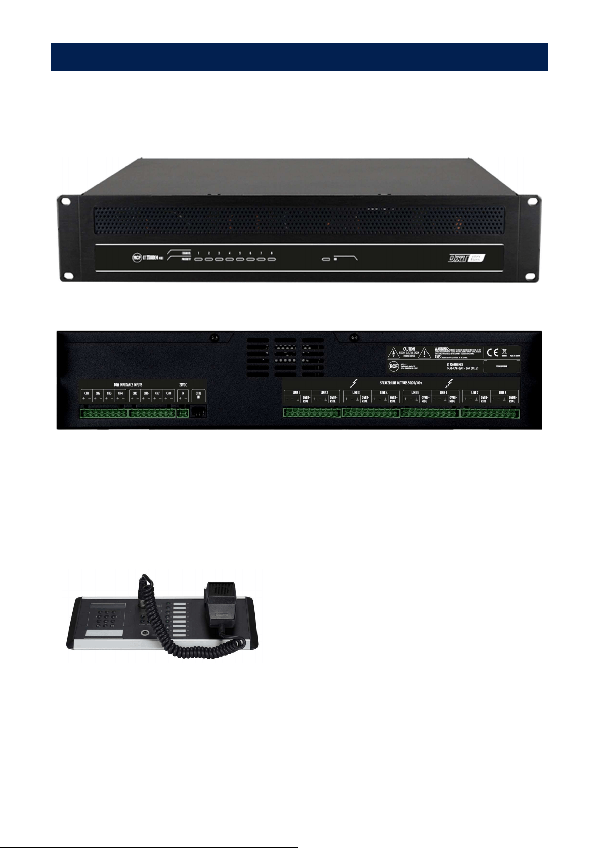
DESCRIPTION
MU 7100EN MKII is the main unit of the innovative RCF DXT 7000EN system, which has been designed to fulfil all requirements of
EN 54-16 and EN 60849 standards.
RCF DXT 7000EN sound system is suitable for different purposes, such as evacuation, paging and background music.
Typical targets are halls, schools, shopping centres, hospital, railway stations, hotels, etc.
Up to 64 MU 7100EN MKII can be linked together to get an extended system including many paging stations and up to 512 speaker
lines / paging zones.
The main unit can play all necessary evacuation and alarm messages previously stored to its digital memory.
It is possible to control, manage and monitor MU 7100EN MKII over TCP/IP based Local Area Network.
The 8 digital internal amplifiers are reliable and their efficiency is excellent (> 90%), that means less heat dissipation and smaller
capacity requirement for unbreakable power supply sources (UPS) and batteries used in sound evacuation systems.
The whole signal path from paging microphones to speaker lines is completely and automatically monitored against faults.
All properties and functions of the system are specified with Windows® based DXT 7000EN configuration software and loaded to the
master unit through either LAN network or its USB port.
MAIN FEATURES
•
In compliance with EN 54-16 and EN 60849 standards (voice evacuation system)
•
Link of up to 64 MU 7100EN MKII main units (up to 512 paging zones)
•
8 independent 80W RMS (on a 8-ohm load) amplifiers
•
7-input x 8-output digital audio matrix
•
7 analogue audio inputs, mic/line level
•
8 I²S digital audio inputs (two ports)
•
Built-in message player
•
Messages stored on USB flash drives
•
Internal timer
•
Phantom voltage for electret microphones
•
8 control (logic) inputs
•
8 control (logic) outputs
•
System connection through 'System Bus' and 'Local Bus' (or redundant system bus)
•
Wiring with CAT5/6/7 cable
•
Internal digital signal processor (DSP)
•
Volume and source controls on user panels
7
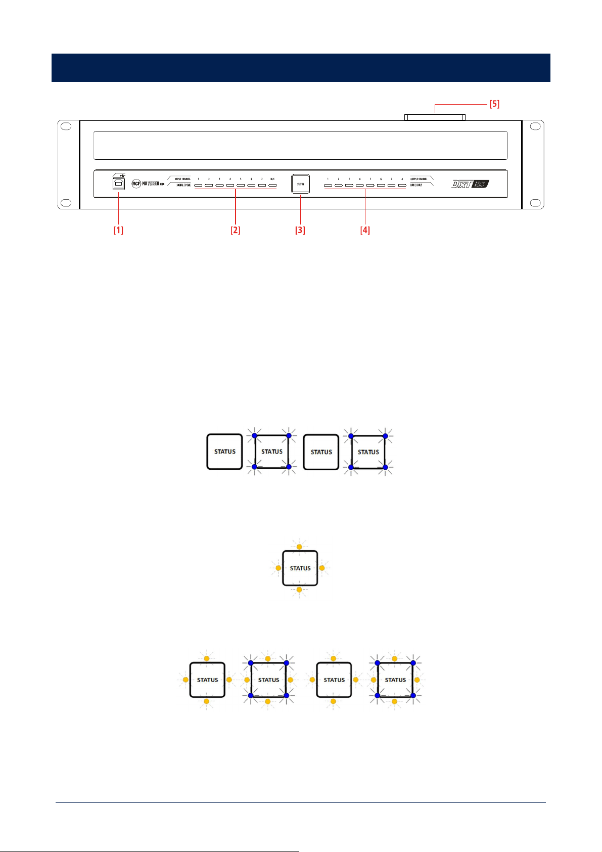
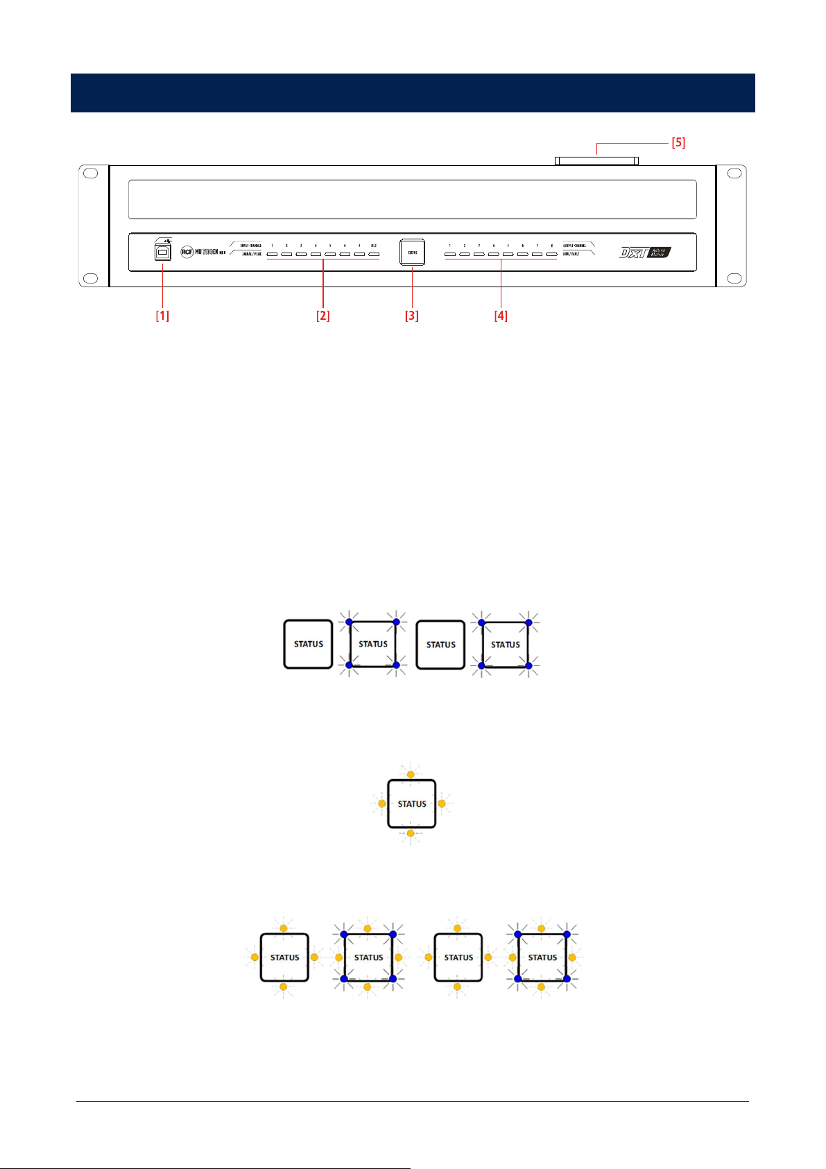
FRONT PANEL
[1] USB (B) port for PC link. Used for system programming, monitoring and administration.
[2] Input signal indicators (one per channel). A blue LED indicates the audio signal presence in the respective channel, a red LED
instead indicates a too high input signal level.
BUS indicator LED is active if the spare master change-over feature is activated. Blue indicates that the master unit is commanding
the system, red instead indicates that the spare master is active.
[3] Status indicator: in normal operation (without any system faults), the four blue corner LEDs are steady lit. Dim blue light indicates
that the device is powered but not in its active state.
When the system is in stand-by mode, the blue LEDs are blinking.
When the system is fault monitored and one or more faults are detected, the blue LEDs are turned off and four orange LEDs start
blinking.
When one or more system faults have been detected, orange LEDs are steady lit and the blue ones are blinking.
When all system faults are cleared, orange LEDs are turned off.
Faults can be cleared through paging consoles having proper rights or alternatively by using a PC connected to a master unit. The
triggering of the control input function 'No monitoring' also clears faults. All faults (but the system fault) are cleared automatically if
the fault cause disappears.
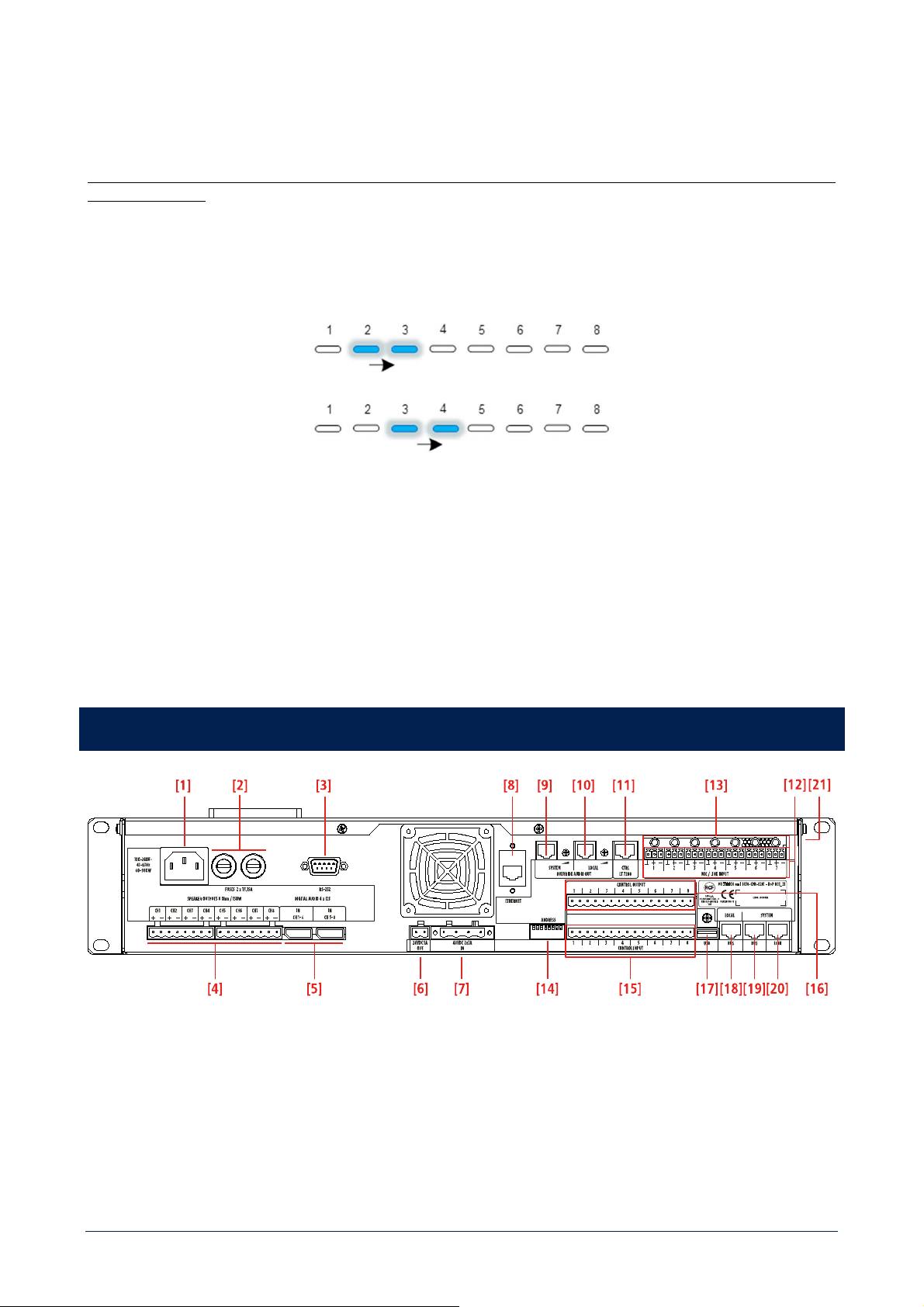
8
[4] Amplifier output / speaker line fault indicators.
Each blue LED indicates the audio signal presence (or monitoring pilot tone) in its respective speaker line. Note: the indicator operation
has been made slow intentionally; in case of signal absence, a blue LED may still glow for several seconds.
If the amplifier and loudspeaker line monitoring is in use, a possible fault in any amplifier or speaker line is indicated
by an orange LED.
If no audio signals are present on outputs, amplifier or speaker line monitoring sequence can be seen by active blue LED running
slowly channel by channel.
[5] Top cover fan. There are two temperature-controlled fans inside the unit, one on the back and another one placed on the top
cover.
At least 25 mm free space must be left above each MU 7100EN MKII unit to ensure proper cooling.
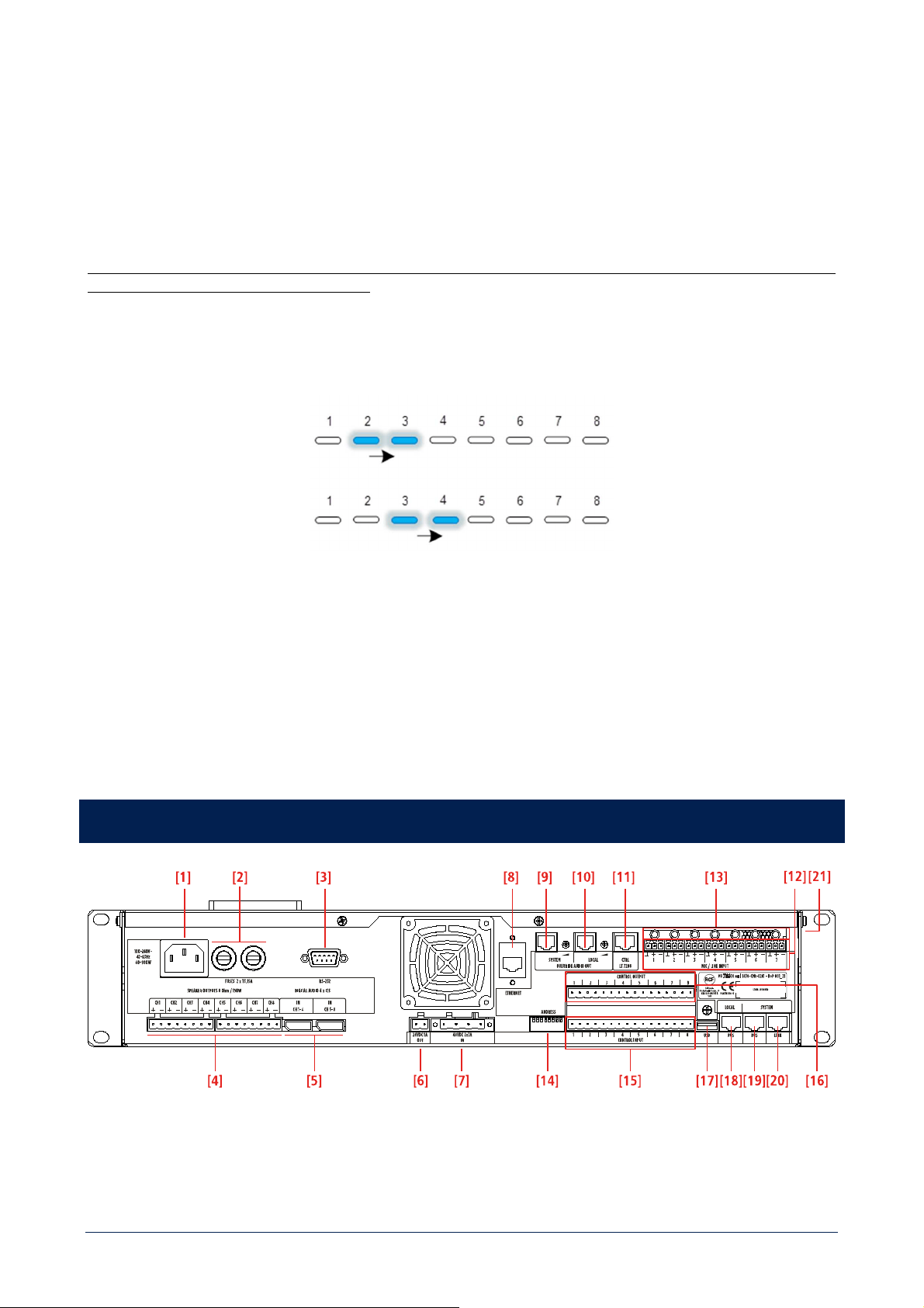
REAR PANEL
[1] IEC connector for power cord (to be connected to a mains earthed electric socket only).
[2] Fuses: 2 pcs. of T3.15A (5x20mm). Always use suitable fuses only. Before changing a fuse, the power cord must be detached from
the mains socket.
[3] RS-232 serial port for service purpose.

9
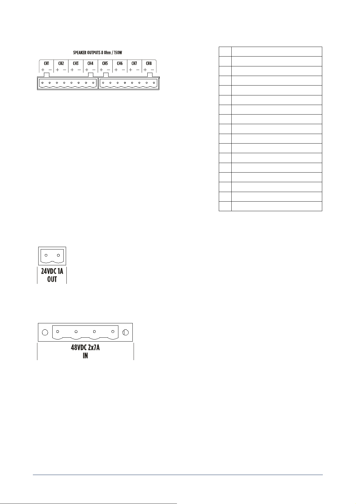
[4] Output connectors for either loudspeakers or a LT 7208EN MKII 'line transfer unit'. Connectors are removable screw terminal
strips, max. wire section is 2.5 mm². Minimum load impedance is 8 Ω.
[5] I2S digital audio inputs (two connectors: CH 1-4 and CH 5-8).
[6] 24 V power supply output, max. 1 A. This output can be linked to LT 7208EN MKII power supply input.
[7] Dual 48 V dc input (2 x 7 A) for secondary power supply (batteries / power supply units).
[8] LAN connector (Ethernet).
[9] System bus override audio output (0 dB) with volume control and relay contacts.
[10] Local bus override audio output (0 dB) and volume control and relay contacts.
[11] CTRL LT 7208: control output for LT 7208EN MKII 'line transfer unit'.
[12] Analogue audio input 1 - 7 connectors.
Note: Audio input +48 V dc Phantom on/off dip-switches are on the lateral side [21].
[13] Gain trimmers for analogue audio inputs 1-7.
Input sensitivity can be adjusted from – 45 dBu to +6 dBu.
[14] 8 DIP-switches for digital address setting of each MU 7100EN MKII.
[15] Connector with 8 control (logic) inputs that can be activated by external dry contacts.
[16] Connector with 8 control (logic) outputs.
[17] USB (A) port for USB flash drives.
[18] LOCAL BUS connector (for DXT 7000EN product family devices and mountings).
[19] SYSTEM BUS connector (for DXT 7000EN product family devices and mountings).
Furthermore, system bus can be used to connect main units together.
[20] LINK system bus connector (second system bus port).
[21] +48 V dc Phantom on/off dip-switches of analogue audio input 1 - 7 [12].
10
OTHER SYSTEM COMPONENTS
LT 7208EN MKII – LINE TRANSFORMER UNIT
FRONT VIEW
REAR VIEW
It turns 8 Ω outputs of MU 7100EN MKII into either 70 V or 100 V (factory setting) constant voltage lines for speakers with
transformers.
Output power alternatives: 8 x 80W, 4 x 160 W and 2 x 320W or any combination from these.
It includes also line specific 24V dc outputs for override relays.
BM 7608DFM – FIREMEN PAGING CONSOLE
• High quality handheld monitored microphone
• 8 zone / function buttons
• Audio input (3.5 mm TRS jack socket) for an external
program source
• Connection through CAT5/6/7 cable to local or system bus
• Up to 32 paging consoles linked to the system bus and 8
to the local bus
• Backlit LCD
• Numeric keyboard
• Menu based user interface
11
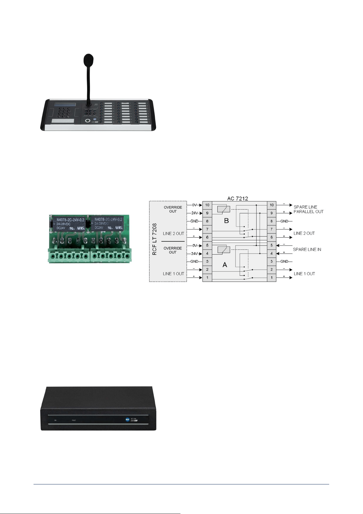
BM 7624D – PAGING CONSOLE
• Flexible gooseneck with monitored microphone
• 24 zone / function buttons
• Audio input (3.5 mm TRS jack socket) for an external
program source
• Connection through CAT5/6/7 cable to local or system bus
• Up to 32 paging consoles linked to the system bus and 8
to the local bus
• Backlit LCD
• Numeric keyboard
• Menu based user interface
AC 7212 – SPARE AMPLIFIER CHANGE-OVER BOARD FOR LT 7208EN MKII
AC 7212 is a board to insert a spare amplifier for 2 outputs of the LT 7208EN MKII unit. Each board has 2 main speaker line inputs,
spare amplifier input and output, 2 relays.
AC 7212 shall be directly connected to a pair of LT 7208EN MKII 70-100 V speaker outputs.
A board can control 2 outputs (in pairs: 1-2, 3-4, 5-6 or 7-8).
The LT 7208EN MKII override voltage output is used to activate the AC 7212 relay in case of the main amplifier is faulty and switch
the spare amplifier output to the respective speaker line.
MT 7308 – UNIVERSAL MONITORING UNIT
MT 7308 universal monitoring unit makes it possible to
integrate external (constant voltage) amplifiers into the
monitored DXT 7000EN voice evacuation system. Any
professional single / multichannel amplifier equipped with a 0 ÷
6 dBu balanced audio input and 70/100 V constant voltage
output(s) can be used. One or two MT 7308 can be linked to
each MU 7100EN MKII main unit. An unit can be used for up to
eight external amplifiers (and its speaker line monitoring).
Max. power for each external amplifier: 500 W.
The eighth amplifier can be set as spare that automatically
replaces a faulty one.
12
EL 7001 – END OF LINE UNIT
'End of line' units need to be added when speaker line
monitoring is required.
A unit shall be installed at the end of each line, near the last
installed speaker.
It is suitable for 70 – 100 V speaker lines (not necessary for an
8 Ω load).
MU 7100EN MKII OPERATION AND USE
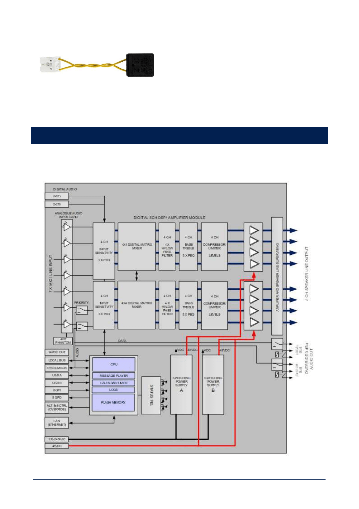
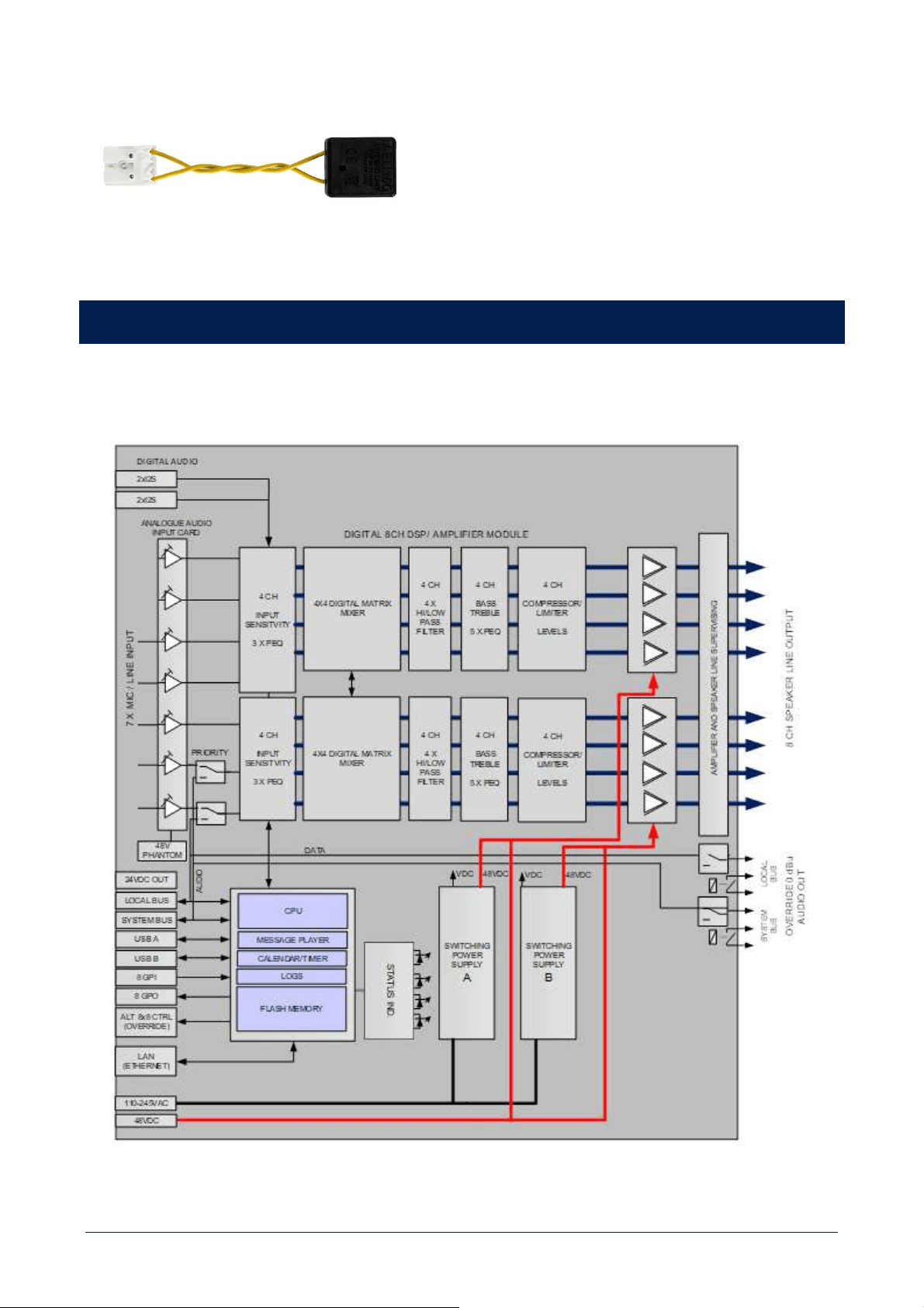
MU 7100EN MKII BLOCK DIAGRAM

13
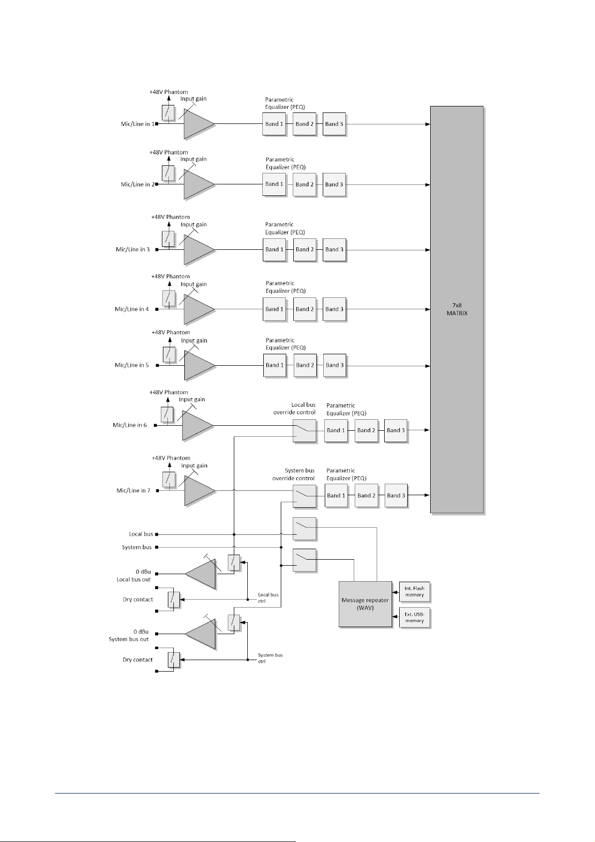
ANALOGUE AUDIO INPUTS
MU 7100EN MKII has 7 balanced analogue audio inputs for external program sources. Each input has a (tool adjustable) gain control
that allows the connection of either a microphone or line level program source. Adjustment screws are located above each input
connector.
The input connector is a detachable terminal block, of which max. wire section is 1.5 mm².
48 V dc 'Phantom' voltage for electret microphones can be turned on with dip-switches.
14
Input 5 can have VOX priority, input 6 is muted during a higher priority of the local bus paging, input 7 is muted during a higher
priority of the system bus paging.
ROUTING AND AMPLIFIER OUTPUTS
MU 7100EN MKII includes 8 digital amplifiers and signal processing for each output channel.
Low impedance (8 Ω) speakers can be directly connected to the rear SPEAKER outputs [4].
If the system is based on constant voltage lines, the speaker outputs shall be connected to LT 7208EN MKII 'Line Transfer' unit inputs
to get 8 outputs x 80 W at 70 /100 V.
The output line voltage setting (70 / 100 V) is internal and made by changing the output tapping of each transformer (this setting is
to be carried out by an authorized service centre).
Default setting is 100 V.
If the needed loudspeaker line power is more than 80 W, several outputs (in groups made of 2, 3 or 4) can be connected together (in
parallel) by making a 'locked group' to obtain 160 / 240 / 320 W line outputs. The 'locked group' is created by using the configuration
software: the settings of the first amplifier are copied to the other channels of the same group, allowing all group amplifiers to operate
in the same identical way.
15
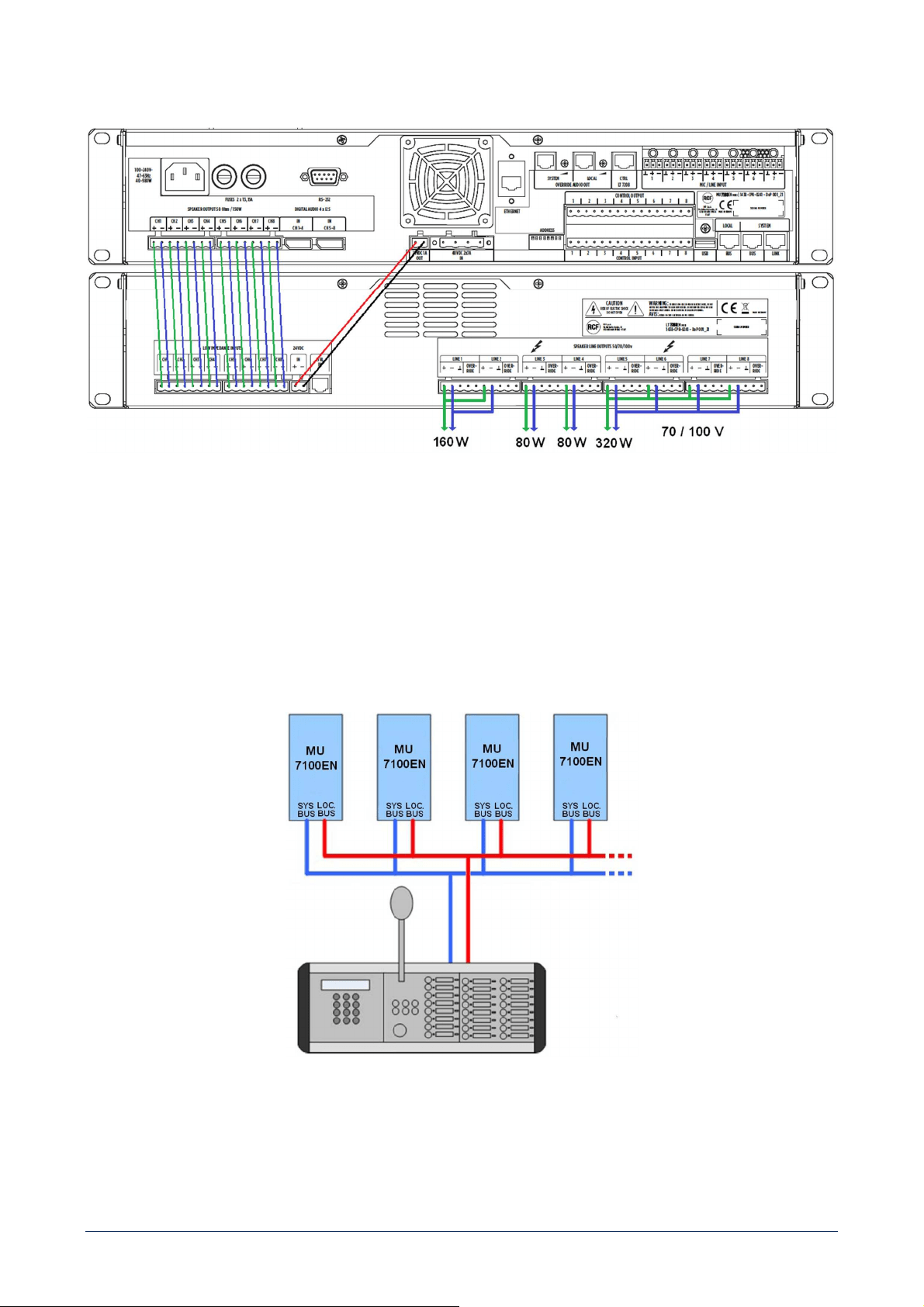
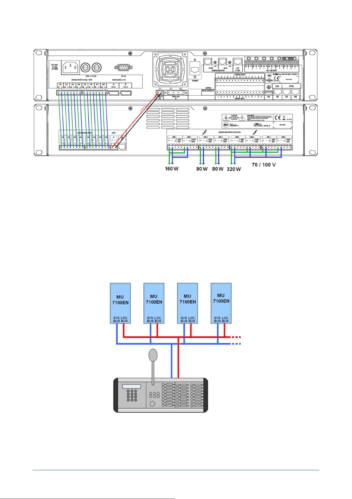
Example of connection MU 7100EN MKII < > LT 7208EN MKII for 80 / 160 / 320 W lines:
SYSTEM AND LOCAL BUS
'System bus' is a control bus covering the whole system. The system components are monitored through this bus. All MU 7100EN
MKII main units are connected to the system bus, control panels and devices can be connected to either the system bus or a local bus.
The system bus wiring can be made by using CAT5/6/7 cable.
All devices connected are powered through the bus (no external power supplies are needed).
All buses contain also one balanced audio channel.
IMPORTANT: the local bus can be extended (when set in the PC software) as a spare / redundant system bus.
Main system bus and local bus used as spare bus
16
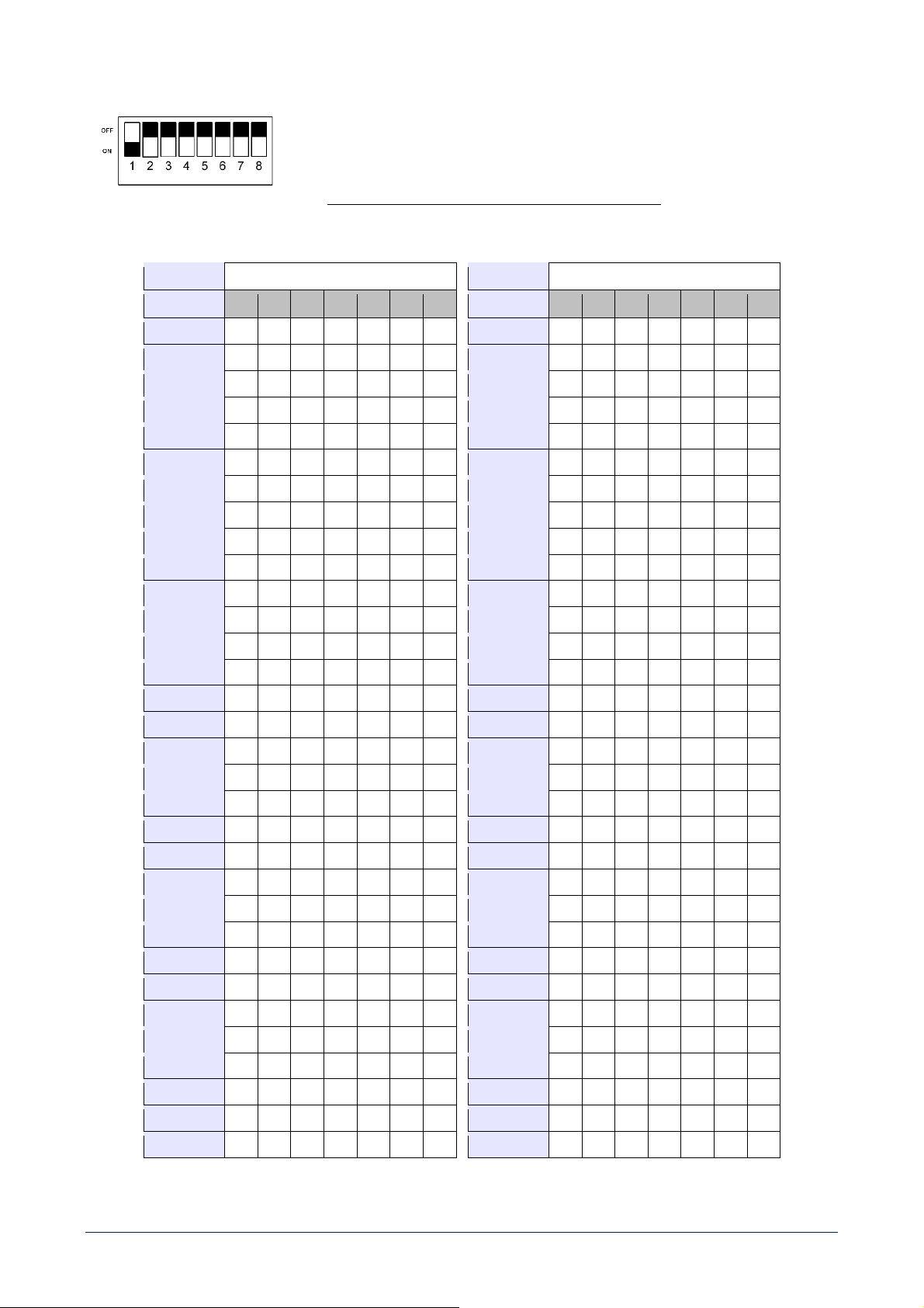
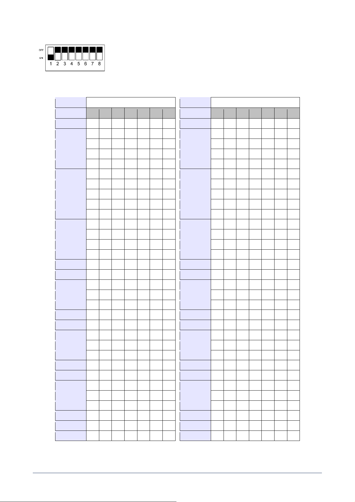
UNIT DIGITAL ADDRESS
Each MU 7100EN has an individual digital address that is set through the first 7 of the 8
DIP-switches located at the rear panel.
Each digital address must be set before powering the system.
Two or more devices cannot have the same digital address.
Digital address setting through DIP-switches:
ADDRESS DIP-SWITCHES
ADDRESS DIP-SWITCHES
1 2 3 4 5 6 7
1 2 3 4 5 6 7
1
ON
OFF OFF OFF OFF OFF OFF 33
ON
OFF OFF OFF OFF
ON
OFF
2 OFF
ON
OFF OFF OFF OFF OFF 34 OFF
ON
OFF OFF OFF
ON
OFF
3
ON ON
OFF
OFF
OFF
OFF
OFF
35
ON ON
OFF
OFF
OFF
ON
OFF
4
OFF
OFF
ON
OFF
OFF
OFF
OFF
36
OFF
OFF
ON
OFF
OFF
ON
OFF
5
ON
OFF
ON
OFF OFF OFF OFF 37
ON
OFF
ON
OFF OFF
ON
OFF
6 OFF
ON ON
OFF OFF OFF OFF 38 OFF
ON ON
OFF OFF
ON
OFF
7
ON ON ON
OFF OFF OFF OFF 39
ON ON ON
OFF OFF
ON
OFF
8 OFF OFF OFF
ON
OFF OFF OFF 40 OFF OFF OFF
ON
OFF
ON
OFF
9
ON
OFF
OFF
ON
OFF
OFF
OFF
41
ON
OFF
OFF
ON
OFF
ON
OFF
10
OFF
ON
OFF
ON
OFF
OFF
OFF
42
OFF
ON
OFF
ON
OFF
ON
OFF
11
ON ON
OFF
ON
OFF OFF OFF 43
ON ON
OFF
ON
OFF
ON
OFF
12 OFF OFF
ON ON
OFF OFF OFF 44 OFF OFF
ON ON
OFF
ON
OFF
13
ON
OFF
ON ON
OFF OFF OFF 45
ON
OFF
ON ON
OFF
ON
OFF
14 OFF
ON ON ON
OFF OFF OFF 46 OFF
ON ON ON
OFF
ON
OFF
15
ON ON ON ON
OFF
OFF
OFF
47
ON ON ON ON
OFF
ON
OFF
16
OFF
OFF
OFF
OFF
ON
OFF
OFF
48
OFF
OFF
OFF
OFF
ON ON
OFF
17
ON
OFF OFF OFF
ON
OFF OFF 49
ON
OFF OFF OFF
ON ON
OFF
18 OFF
ON
OFF OFF
ON
OFF OFF 50 OFF
ON
OFF OFF
ON ON
OFF
19
ON ON
OFF OFF
ON
OFF OFF 51
ON ON
OFF OFF
ON ON
OFF
20 OFF OFF
ON
OFF
ON
OFF OFF 52 OFF OFF
ON
OFF
ON ON
OFF
21
ON
OFF
ON
OFF
ON
OFF
OFF
53
ON
OFF
ON
OFF
ON ON
OFF
22
OFF
ON ON
OFF
ON
OFF
OFF
54
OFF
ON ON
OFF
ON ON
OFF
23
ON ON ON
OFF
ON
OFF OFF 55
ON ON ON
OFF
ON ON
OFF
24 OFF OFF OFF
ON ON
OFF OFF 56 OFF OFF OFF
ON ON ON
OFF
25
ON
OFF OFF
ON ON
OFF OFF 57
ON
OFF OFF
ON ON ON
OFF
26 OFF
ON
OFF
ON ON
OFF OFF 58 OFF
ON
OFF
ON ON ON
OFF
27
ON ON
OFF
ON ON
OFF
OFF
59
ON ON
OFF
ON ON ON
OFF
28
OFF
OFF
ON ON ON
OFF
OFF
60
OFF
OFF
ON ON ON ON
OFF
29
ON
OFF
ON ON ON
OFF OFF 61
ON
OFF
ON ON ON ON
OFF
30 OFF
ON ON ON ON
OFF OFF 62 OFF
ON ON ON ON ON
OFF
31
ON ON ON ON ON
OFF OFF 63
ON ON ON ON ON ON
OFF
32 OFF OFF OFF OFF OFF
ON
OFF 64 OFF OFF OFF OFF OFF OFF
ON
Note: the address is only read when turning the system on.

17
The MU 7100EN MKII unit having address 1 is always the 'master' that controls the operation of the whole system. The MU 7100EN
MKII unit having address 2 is a spare 'master': if it cannot be connected to the 'master' unit, it will take the system control.
Note: check all addresses twice before powering the system! An incorrect address would lock the system, which would need to be
rebooted (after setting the right addresses).
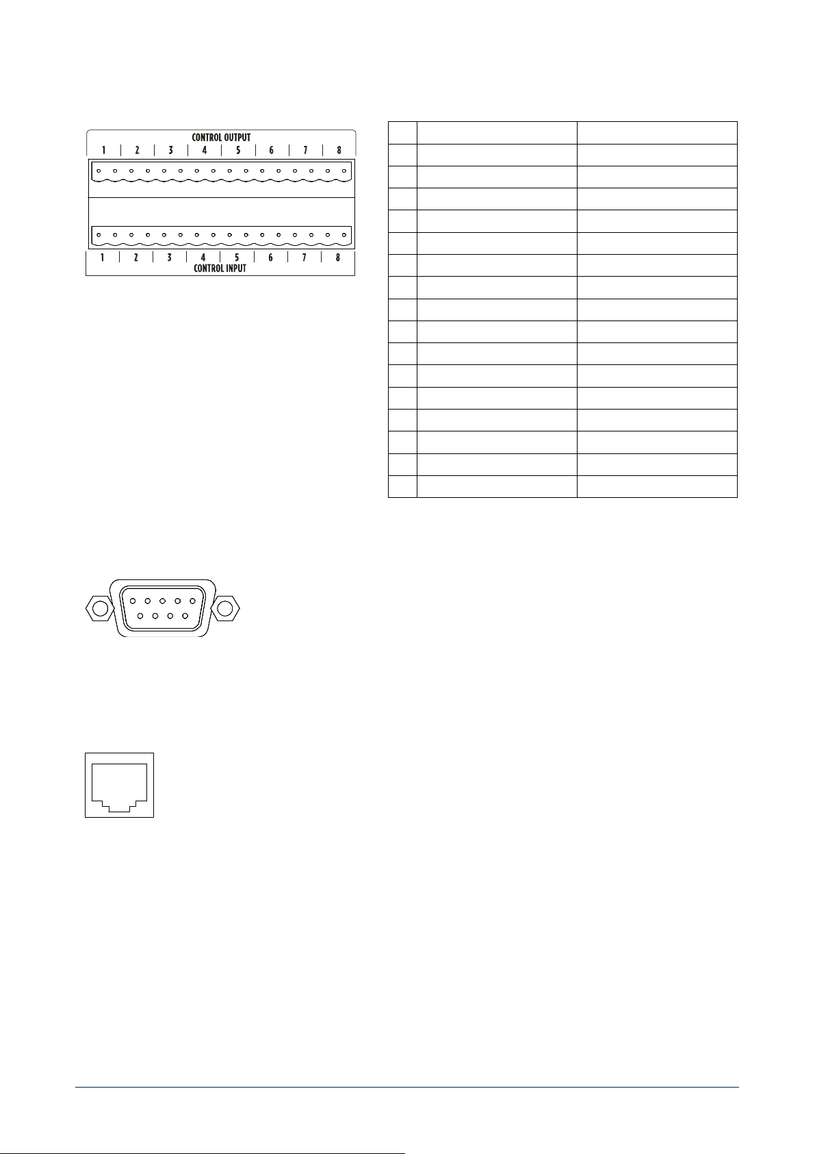
CONTROL INPUTS
MU 7100EN is equipped with 8 control (logic) inputs for external dry contacts.
Each control input function can be independently programmed via PC software and activated by either closing or opening contacts.
CONTROL OUTPUTS
MU 7100EN has 8 control (logic) outputs, 'open collector' type, which can directly drive 24 V dc relays. Maximum total relay current
is 300 mA.
Each control output function can be independently programmed via PC software.
RS-232 PORT
(9-PIN D-SUB connector)
This port is for factory service only.
LAN (ETHERNET) PORT
MU 7100EN MKII is equipped with 100 MHz LAN port (TCP/IP) for system configuration, control (Local Bus and System Bus data) and
monitoring.
Each unit has its own (adjustable) system IP address.
USB (A) PORT
A USB flash drive having recorded messages (WAV files that can be played through the system) can be connected to the USB (A) port.
Note: any message that is used in the configuration, but not stored to the internal memory yet, will be automatically loaded after the
first usage (from the USB-memory stick to the internal flash memory).
USB (B) PORT
USB port for PC link (when the LAN port is not used).
When using the DXT 7000EN
configuration software, all system properties can be configured through the 'master' unit. All necessary
data are sent from the 'master' MU 7100EN MKII to all the others and devices connected to both the system bus and local bus.
A USB cable to link the 'master' MU 7100EN MKII unit to a PC is included.
SYSTEM CONFIGURATION
About the system configuration, please refer to the DXT 7000EN software user manual.

18
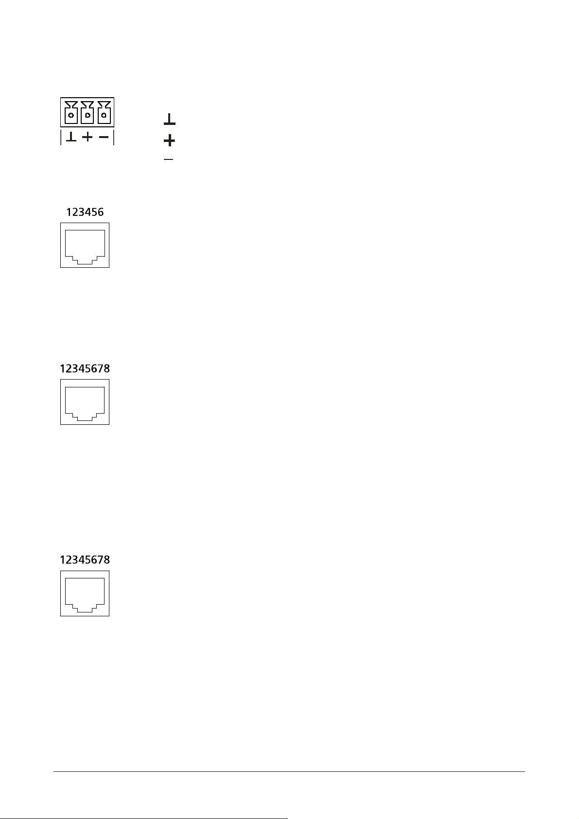
CONNECTORS
AUDIO INPUTS 1 - 7
Pins:
ground
hot
cold
SYSTEM AND LOCAL BUS OVERRIDE AUDIO OUTPUTS
RJ-11 connector
1 ground
2 audio (+ hot)
3 audio (– cold)
4 relay NC contact
5 relay NO contact
6 relay common contact
LT 7208 CONTROL
RJ-45 connector
1 line 1 open collector control
2 line 2 open collector control
3 line 3 open collector control
4 line 4 open collector control
5 line 5 open collector control
6 line 6 open collector control
7 line 7 open collector control
8 line 8 open collector control
SYSTEM BUS AND LINK (LINKED TOGETHER IN PARALLEL) AND LOCAL BUS
RJ-45 connector
Note: audio and data signals must be always connected as separate twisted pairs.
1 System/Local audio (+ hot)
2 System/Local audio (– cold) (1-2 twisted pair)
3 Audio GND
4 Digital GND
5 +12V
6 +24V
7 Data (A)
8 Data (B) (7-8 twisted pair)
19
CONTROL IN/OUT 1 - 8
Removable 16-pin screw terminal strips. Max. wire section: 2.5 mm².
Control input pins Control output pins
1
Control 1 Control 1 (open collector)
2
+12V +24V
3
Control 2 Control 2 (open collector)
4
+12V +24V
5
Control 3 Control 3 (open collector)
6
+12V +24V
7
Control 4 Control 4 (open collector)
8
+12V +24V
9
Control 5 Control 5 (open collector)
10
+12V +24V
11
Control 6 Control 6 (open collector)
12
+12V +24V
13
Control 7 Control 7 (open collector)
14
+12V +24V
15
Control 8 Control 8 (open collector)
16
+12V +24V
RS-232 PORT
Pins
1 5 GND
2 Rx Data 6
3 Tx Data 7
4 8
LAN PORT (ETHERNET)
RJ45 Type CAT6e port 10/100/100Base-T(X)
20
SPEAKER OUTPUTS 1 - 8
Removable 8-pin screw terminal strips. Max. wire section: 2.5 mm².
Pins (left to right)
1
Channel 1 output +
2
Channel 1 output -
3
Channel 2 output +
4
Channel 2 output -
5
Channel 3 output +
6
Channel 3 output -
7
Channel 4 output +
8
Channel 4 output -
9
Channel 5 output +
10
Channel 5 output -
11
Channel 6 output +
12
Channel 6 output -
13
Channel 7 output +
14
Channel 7 output -
15
Channel 8 output +
16
Channel 8 output -
24 V DC POWER OUTPUT FOR LT 7208EN MKII
Removable 2-pin screw terminal strip.
Pins (left to right):
1 +
2 –
MU 7100EN 48 V dc (redundant) power input (max. 2 x 7 A)
Removable 4-pin screw terminal strip.
Pins (left to right):
1 + (1
st
pair)
2 - (1
st
pair)
3 + (2
nd
pair)
4 - (2
nd
pair)
FUNCTIONAL FEATURES
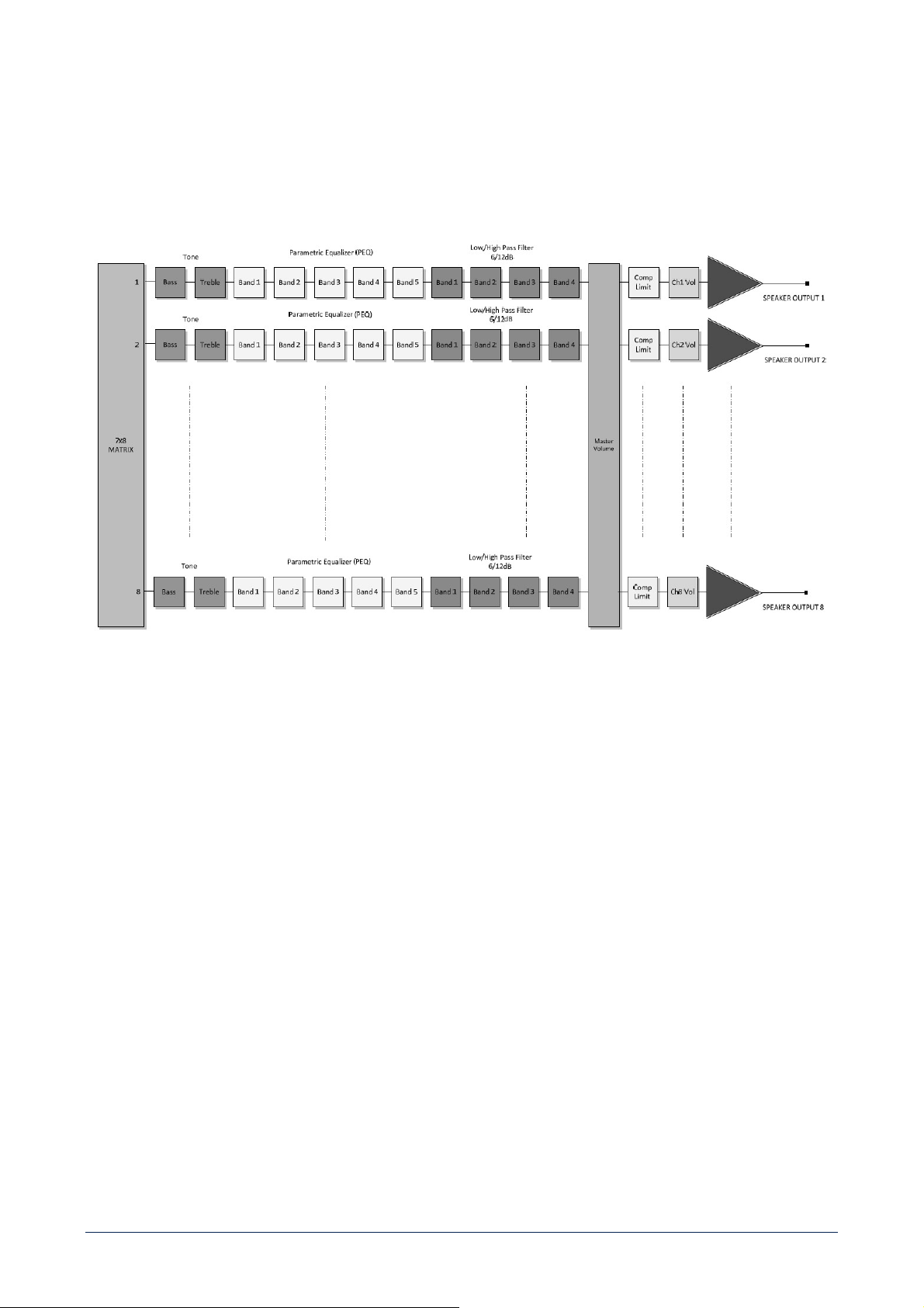
SIGNAL PROCESSING AND ROUTING CHARACTERISTICS
• True digital signal path and processing, digital power amplifiers, efficiency up to 92%.
• Analogue audio inputs, adjustable gain (microphone to line).
• Phantom power supply (for electret microphones).
• Built-in 'wave' file message player (up to 128 messages).

21
DIGITAL SIGNAL PROCESSING ON EACH INPUT
• 3-band parametric equalizer.
• Digital routing to any output channel, level control.
DIGITAL SIGNAL PROCESSING ON EACH OUTPUT
• Tone controls: bass and treble.
• 5-band parametric equalizer.
• 4 filters with freq. adjustment, selectable high-pass or low-pas, slope 6-12 dB/oct. .
• Compressor / limiter.
• Level control.
CONTROL BUSES AND I/O INTERFACES
• Local bus interface for paging units and control devices.
• Local bus can also be used as spare / redundant system bus.
• System bus interface for paging and control devices.
• System bus link to the next MU 7100EN MKII central unit.
• USB B port for PC link.
• USB A port for external flash drives.
• 8 programmable control (logic) inputs.
• 8 programmable control (logic) outputs.
• Control output to LT 7208EN MKII.
• RS-232 serial port for service.
TIME BASED FUNCTIONS
• Internal clock (set by PC software).
• 25-year automatic summer / winter time setting.
• Up to 125 programmable time based events.
LOG FUNCTIONS
• System event log.
• System error log.
SYSTEM FUNCTIONS
• The system is expandable by linking up to 64 MU 7100EN MKII units via the system (or local) bus.
• Unique selectable address for each MU 7100EN MKII.
• Up to 512 speaker lines and paging zones.
• Audio program groups for background music.
SYSTEM MONITORING
• Equipment and system monitoring according to the EN54-16 and EN 60849 standards.
• Automatic 'master' MU 7100EN MKII change over to the 'spare-master' MU 7100EN MKII (in case of the 'master' unit is faulty).
• Automatic spare amplifier change over.

22
• Power supply voltage control.
• Temperature monitoring.
• Fan motor monitoring.
MAINTENANCE
It is recommended a minimum of two scheduled maintenance inspections a year.
A responsible person shall be nominated to ensure that the procedure continues to be carried out properly.
Maintenance instructions
• Each MU 7100EN MKII has two cooling fans with the dust filter, one is on the cover plate and the other on the rear panel. Clean
filters by removing plastic fans filter holder.
• Visual checking:
• Check all indicators in the rack units and paging/control consoles.
• Check the condition of any system connector or wire.
• Secondary power test, if applicable.
• General operational test when the primary power source (mains) is missing.
• Operation system test:
• The system test is to be carried out to verify the system works correctly and manual / automatic messages or announcements
are heard clearly.
• Page different zones to ensure that all speaker lines are OK.
• The test should be done with standard announcements and alarms too.
• The test should be planned together with the fire system testing.
23
AVVERTENZE PER LA SICUREZZA
I simboli utilizzati in questo documento notificano importanti
istruzioni operative e avvertimenti che devono essere seguiti
attentamente.
CAUTELA
Importante istruzione operativa:
notifica un pericolo che
potrebbe danneggiare il
prodotto, compresa la perdita di
dati.
ATTENZIONE
Avvertimento importante
riguardante l’uso di voltaggi
pericolosi e il potenziale rischio
di shock elettrico, lesioni
personali o morte.
NOTE
IMPORTANTI
Informazioni utili e rilevanti
sull’argomento.
SUPPORTI,
TROLLEY E
CARRRELLI
Informazioni riguardanti
l’utilizzo di supporti, trolley e
carrelli. Suggerisce di muovere
con estrema cautela e di non
inclinare il carico.
SMALTIMENTO
Questo simbolo indica che il
prodotto non deve essere
smaltito con i rifiuti ordinari,
così come indicato nella
direttiva WEEE (2012/19/ EU) e
nelle normative nazionali in
vigore.
NOTE IMPORTANTI
Questo manuale contiene informazioni importanti sull’uso
corretto e sicuro del dispositivo. Prima di collegare e utilizzare
questo prodotto, leggere attentamente questo manuale di
istruzioni e tenerlo a portata di mano per riferimenti futuri. Il
manuale deve essere considerato parte integrante di questo
prodotto e deve accompagnarlo in caso di cambio proprietà
come riferimento per la corretta installazione e utilizzo nonché
per le precauzioni di sicurezza. RCF S.p.A. non si assume
alcuna responsabilità per l’installazione e / o l’uso errati di
questo prodotto.
PRECAUZIONI DI SICUREZZA
1. Tutte le precauzioni, in particolare quelle di sicurezza,
devono essere lette con particolare attenzione, in quanto
forniscono informazioni importanti.
2. Alimentazione principale da rete elettrica
a. La tensione di rete è sufficientemente elevata da
comportare un rischio di folgorazione; installare e
collegare questo prodotto prima di collegarlo.
b. b. Prima di accendere, assicurarsi che tutti i
collegamenti siano stati eseguiti correttamente e che la
tensione della rete corrisponda alla tensione indicata
sulla targhetta dei dati sull’unità, in caso contrario,
contattare il rivenditore RCF.
c. Le parti metalliche dell’unità sono messe a terra
attraverso il cavo di alimentazione. Un apparecchio con
costruzione di CLASSE I deve essere collegato a una
presa di corrente con un collegamento di terra di
protezione.
d. Proteggere il cavo di alimentazione da danni; assicurarsi
che sia posizionato in modo tale da non poter essere
calpestato o schiacciato da oggetti.
e. Per evitare il rischio di scosse elettriche, non aprire mai
questo prodotto: non sono previste parti interne alle
quali l’utente debba accedere.
f. Fare attenzione: nel caso di un prodotto provvisto solo
di connettori POWERCON e senza cavo di alimentazione,
congiuntamente ai connettori POWERCON tipo
NAC3FCA (alimentazione) e NAC3FCB (alimentazione),
devono essere usati i seguenti cavi di alimentazione
conformi alla norma nazionale:
- EU: cavo di tipo H05VV-F 3G 3x2.5 mm2 -
Standard IEC 60227-1
- JP: cavo di tipo VCTF 3x2 mm2; 15Amp/120V~ -
Standard JIS C3306
- US: cavo di tipo SJT/SJTO 3x14 AWG;
15Amp/125V~ - Standard ANSI/UL 62
3. Assicurarsi che nessun oggetto o liquido penetri in
questo prodotto poiché ciò potrebbe causare un corto
circuito. Questo apparecchio non deve essere esposto a
gocciolamenti o spruzzi. Nessun oggetto riempito di
liquido, come vasi, deve essere posizionato su questo
apparecchio. Nessuna fiamma libera (come candele
accese) deve essere posizionata su questo apparecchio.
4. Non tentare mai di eseguire operazioni, modifiche o
riparazioni non espressamente descritte nel presente
manuale. Contattare il centro di assistenza autorizzato o
personale qualificato qualora si verifichi una delle
seguenti condizioni:
- Il prodotto non funziona (o funziona in
modo anomalo).
- Il cavo di alimentazione è stato
danneggiato.
- Oggetti o liquidi sono entrati nell’unità.
- Il prodotto ha subìto un forte urto.
5. Se questo prodotto non viene utilizzato per un lungo
periodo, scollegare il cavo di alimentazione.
6. Se questo prodotto inizia a emettere strani odori o fumo,
spegnerlo immediatamente e scollegare il cavo di
alimentazione.
7. Non collegare questo prodotto ad apparecchiature o
accessori non previsti. Per l’installazione sospesa,
24
utilizzare solo i punti di ancoraggio dedicati e non
tentare di appendere questo prodotto utilizzando
elementi non idonei o non specifici per questo scopo.
Verificare inoltre l’idoneità della superficie di supporto a
cui è ancorato il prodotto (parete, soffitto, struttura, ecc.)
a dei componenti utilizzati per il fissaggio (tasselli, viti,
staffe non fornite da RCF ecc.) che devono garantire
sicurezza del sistema / installazione nel tempo, anche
considerando, ad esempio, le vibrazioni meccaniche
normalmente generate dai trasduttori. Per evitare il
rischio di caduta dell’apparecchiatura, non impilare più
unità di questo prodotto a meno che questa possibilità
non sia specificata nel manuale dell’utente.
8. RCF S.p.A. raccomanda vivamente che questo prodotto
sia installato solo da installatori professionisti qualificati
(o aziende specializzate) che possono garantire la
corretta installazione e certificarlo secondo le normative
vigenti. L’intero sistema audio deve essere conforme agli
standard e alle normative vigenti in materia di sistemi
elettrici.
9. Supporti, trolley e carrelli.
L’apparecchiatura deve essere utilizzata, ove
necessario, solo su supporti, trolley e carrelli consigliati
dal produttore. L’apparecchiatura / supporto / carrello
deve essere spostata con estrema cautela. Arresti
improvvisi, eccessiva spinta e pavimenti irregolari
possono causarne il ribaltamento. Non inclinare mai.
10. Vi sono numerosi fattori meccanici ed elettrici da
considerare quando si installa un sistema audio
professionale (oltre a quelli strettamente acustici, come
la pressione del suono, gli angoli di copertura, la risposta
in frequenza, ecc.).
11. Perdita dell’udito. L’esposizione a livelli sonori elevati
può causare la perdita permanente dell’udito. Il livello di
pressione acustica che porta alla perdita dell’udito è
diverso da persona a persona e dipende dalla durata
dell’esposizione. Per prevenire un’esposizione
potenzialmente pericolosa a livelli elevati di pressione
acustica, chiunque sia esposto a questi livelli dovrebbe
usare adeguati dispositivi di protezione. Quando viene
utilizzato un trasduttore in grado di produrre alti livelli
sonori, è quindi necessario indossare tappi per le
orecchie o cuffie protettive. Vedere le specifiche tecniche
del manuale per conoscere il livello massimo di pressione
sonora.
PRECAUZIONI OPERATIVE
- Posizionare questo prodotto lontano da qualsiasi fonte
di calore e garantire sempre un’adeguata circolazione
dell’aria attorno ad esso.
- Non sovraccaricare questo prodotto per molto tempo.
- Non forzare mai gli elementi di controllo (tasti,
manopole, ecc.).
- Non utilizzare solventi, alcool, benzene o altre sostanze
volatili per pulire le parti esterne di questo prodotto.
NOTE IMPORTANTI
Per evitare il verificarsi di disturbi sui cavi di segnale in linea,
utilizzare solo cavi schermati ed evitare di avvicinarli a:
- Apparecchiature che producono campi
elettromagnetici ad alta intensità
- Cavi di alimentazione
- Linee di altoparlanti
ATTENZIONE! CAUTELA! Per
evitare il rischio di incendi o scosse elettriche, non
esporre mai questo prodotto a pioggia o umidità.
ATTENZIONE! Per evitare il rischio di
scosse elettriche, non collegare all’alimentazione
di rete mentre la griglia è rimossa.
WARNING! Per ridurre il rischio di scosse
elettriche, non smontare questo prodotto se non si
è qualificati. Per l’assistenza rivolgersi a personale
di assistenza qualificato.
SMALTIMENTO CORRETTO DEL PRODOTTO
Questo prodotto deve essere consegnato a un sito di raccolta
autorizzato per il riciclaggio di apparecchiature elettriche ed
elettroniche (AEE). Una manipolazione impropria di questo
tipo di rifiuti potrebbe avere un possibile impatto negativo
sull’ambiente e sulla salute umana a causa di sostanze
potenzialmente pericolose che sono generalmente associati
alle AEE. Allo stesso tempo, la vostra collaborazione per il
corretto smaltimento di questo prodotto contribuirà all’utilizzo
efficace delle risorse naturali. Per ulteriori informazioni su dove
sia possibile scaricare le attrezzature per il riciclaggio, si prega
di contattare l’ufficio comunale locale, l’autorità competente
per i rifiuti o il servizio di smaltimento dei rifiuti domestici.
CURA E MANUTENZIONE
Per garantire un servizio di lunga durata, questo prodotto deve
essere utilizzato seguendo questi consigli:
- Se il prodotto deve essere installato all’aperto,
assicurarsi che sia coperto e protetto da pioggia e
umidità.
- Se il prodotto deve essere utilizzato in un ambiente
freddo, riscaldare lentamente le bobine vocali inviando
un segnale di basso livello per circa 15 minuti prima di
inviare segnali ad alta potenza.
25
- Utilizzare sempre un panno asciutto per pulire le
superfici esterne dell’altoparlante e farlo sempre quando
l’alimentazione è spenta
CAUTELA! Per evitare di danneggiare le
finiture esterne non utilizzare solventi per la pulizia
o abrasivi.
ATTENZIONE! CAUTELA! Per gli
altoparlanti alimentati, eseguire la pulizia solo
quando l’alimentazione è spenta.

26
DESCRIZIONE
MU 7100EN MKII è l'unità centrale del sistema RCF DXT 7000EN, progettato per soddisfare pienamente i requisiti richiesti dalle
normative EN 54-16 e EN 60849.
Il sistema audio RCF DXT 7000EN è adatto per sistemi d'evacuazione, di chiamata e di diffusione della musica di sottofondo. Le
applicazioni tipiche sono: saloni, scuole, centri commerciali, ospedali, stazioni ferroviarie, hotel, ecc. .
Fino a 64 MU 7100EN MKII possono essere collegati insieme in modo da ottenere un sistema espanso fino a 512 zone / linee
altoparlanti ed avente molte basi microfoniche.
L'unità centrale può riprodurre tutti i messaggi d'allarme necessari precedentemente memorizzati su una chiave / memoria USB.
È possibile controllare, gestire e monitorare MU 7100EN MKII su una rete locale LAN basata su TCP/IP e trasferire l'audio sul sistema
utilizzando la rete digitale DANTE®.
Gli 8 amplificatori digitali interni sono affidabili e la loro efficienza è ottima (> 90%), che comporta una minor dissipazione di calore
ed un minor carico per i gruppi di continuità (U.P.S.) e/o batterie usati nei sistemi audio adibiti agli annunci d'emergenza.
L'intero percorso del segnale (dalle basi microfoniche alle linee altoparlanti) è completamente ed automaticamente monitorato per la
segnalazione di eventuali guasti.
Tutte le proprietà e le funzioni del sistema sono impostate tramite il software di configurazione DXT 7000EN (su sistema operativo
Windows®) è sono inviate alla prima unità centrale “master” tramite la rete LAN oppure la porta USB.
CARATTERISTICHE PRINCIPALI
•
Soddisfa le normative EN 54-16 EN 60849 (sistemi d'emergenza)
•
Fino a 64 unità centrali MU 7100EN MKII collegabili tra loro (fino a 512 zone)
•
8 amplificatori indipendenti, ciascuno con potenza 80W RMS (su un carico di 8 Ω)
•
Matrice audio digitale con 7 ingressi e 8 uscite
•
7 ingressi audio analogici con sensibilità mic./linea
•
8 ingressi audio digitali I²S (due porte)
•
Riproduttore di messaggi incorporato
•
Messaggi su supporto di memoria (/ chiave) USB
•
Timer interno
•
Alimentazione “Phantom” per microfoni ad elettrete
•
8 ingressi logici
•
8 uscite logiche
•
Collegamento del sistema tramite “System Bus” e “Local Bus” (o “System Bus” di riserva)
•
Cablaggio bus: cavo CAT5/6/7
•
Processore di segnale (DSP) interno
•
Controlli di volume e selezione sorgenti da pannelli utente
27
PANNELLO FRONTALE
[1] Porta USB(B) per la connessione di un computer (PC), utilizzabile per la programmazione, il monitoraggio e l'amministrazione del
sistema.
[2] Indicatori dei segnali d'ingresso (uno per canale). Il LED blu indica la presenza del segnale audio, il LED rosso indica che il livello
del segnale è troppo alto.
Il LED BUS si accende se è attivata la funzione di commutazione automatica dell'unità centrale di riserva; il blu indica che l'unità
centrale “master” sta comandando il sistema, il rosso invece indica che è attiva quella di riserva.
[3] Indicatore di stato: durante il funzionamento normale (senza guasti), i quattro LED blu agli angoli sono accesi fissi.
La luce blu fioca indica invece che il dispositivo è alimentato, ma non attivo.
In modalità “stand-by”, i LED blu lampeggiano.
Nel caso che la supervisione del sistema sia attiva e siano rilevati uno o più guasti / errori, i LED blu sono spenti ed i 4 LED arancioni
lampeggiano.
Quando uno o più guasti / errori sono presenti in modo “stand-by”, i LED arancioni sono accesi e quelli blu lampeggiano.
Dopo aver rimosso tutti i guasti / gli errori, i LED arancioni si spengono.
La segnalazione di guasto può essere rimossa tramite le basi microfoniche (se abilitate) oppure utilizzando il software di configurazione
del sistema DXT 7000EN da PC.
28
Anche l'attivazione della funzione dell'ingresso di controllo “No monitoring” cancella le segnalazioni di guasti, le quali (tranne quella
di sistema) sono cancellate automaticamente se le cause dei guasti non sono più presenti.
[4] Indicatori di guasto alle uscite degli amplificatori o sulle linee diffusori.
Ciascun LED blu indica la presenza del segnale audio (o del tono pilota per il monitoraggio) nella rispettiva linea diffusori. Nota: la
segnalazione del guasto è volutamente ritardata: in caso d'assenza del segnale, il LED blu potrebbe rimanere acceso ancora per
qualche secondo.
Se il controllo dell'amplificatore e della linea diffusori è abilitato, ogni possibile guasto su una linea è indicato
all'accensione del rispettivo LED arancione.
Se non sono presenti segnali audio sulle uscite, la sequenza di monitoraggio dell'amplificatore o della linea di altoparlanti può essere
vista dai LED blu che scorrono canale per canale.
[5] Ventola del coperchio superiore. All'interno dell'unità sono presenti due ventole funzionanti in base alla temperatura: una sul retro
e l'altra posizionata sul coperchio superiore.
È necessario lasciare uno spazio libero di almeno 25 mm sopra ogni unità MU 7100EN MKII per garantire un corretto raffreddamento.
PANNELLO POSTERIORE
[1] Connettore per il cavo d'alimentazione da rete (da collegarsi solo ad una presa con messa a terra).
[2] Fusibili: 2 x T3.15A (5x20mm). Utilizzare sempre e solo fusibili corretti. Prima di sostituire un fusibile, il cavo d'alimentazione deve
essere rimosso dalla presa elettrica.

29
[3] Porta seriale RS-232 (solo per funzioni di servizio).
[4] Uscite per altoparlanti o per il collegamento all'unità LT 7208EN MKII (con trasformatori); il connettore è removibile. Sezione
massima dei conduttori: 2.5 mm². Impedenza minima del carico: 8 Ω.
[5] Ingressi audio digitali I2S (due connettori: CH 1-4 e CH 5-8).
[6] Uscita 24 V, max. 1 A. Questa tensione può essere usata per alimentare l'unità LT 7208EN MKII (tramite l'ingresso 24 VDC IN).
[7] Doppio ingresso 48 V c.c. (2 x 7 A) per alimentazione secondaria (batterie / alimentatori).
[8] Connettore per rete LAN (Ethernet).
[9] Uscita audio (0 dB) del “System Bus” con controllo di volume (regolabile con un cacciavite); include anche un contatto “pulito”.
[10] Uscita audio (0 dB) del “Local Bus” con controllo di volume (regolabile con un cacciavite); include anche un contatto “pulito”.
[11] CTRL LT 7208 Uscita di controllo per l'unità con trasformatori LT 7208EN MKII.
[12] Connettori degli ingressi audio analogici 1-7.
Nota: sul fianco sono presenti dei “dip-switch” (microinterruttori) [21] per attivare l'alimentazione “Phantom” (48 V c.c.) degli ingressi
audio analogici.
[13] Controlli di guadagno degli ingressi audio analogici 1-7.
La sensibilità d'ingresso può essere regolata da –45 dBu a +6 dBu.
[14] 8 microinterruttori (DIP-switch) per impostare l'indirizzo digitale di ogni MU 7100EN MKII.
[15] Connettore con 8 ingressi logici di controllo che possono essere attivati tramite contatti esterni.
[16] Connettore con 8 uscite logiche di controllo.
[17] Porta USB (A) per supporti di memoria / chiavi USB.
[18] Connettore “Local Bus” (per il collegamento di componenti del sistema DXT 7000EN).
[19] Connettore “System Bus” (per il collegamento di componenti del sistema DXT 7000EN).
Può inoltre essere usato per la connessione di più unità centrali MU 7100EN MKII.
[20] Connettore “Link”: secondo connettore “System Bus” (utilizzabile per i collegamenti in cascata).
[21] Microinterruttori (DIP-switch) per attivare l'alimentazione “Phantom” (48 V c.c.) degli ingressi audio analogici 1-7 [12].

30
ALTRI COMPONENTI DEL SISTEMA
LT 7208EN MKII – UNITÀ CON TRASFORMATORI ED USCITE A TENSIONE COSTANTE
VISTA FRONTALE
VISTA POSTERIORE
Converte le uscite altoparlanti 8 Ω dell'unità centrale MU 7100EN MKII in linee 70 V / 100V (impostazione di fabbrica) a tensione
costante per diffusori aventi il trasformatore.
Le possibili combinazioni sono: 8 x 80W, 4 x 160 W e 2 x 320W (o un misto di queste).
Sono presenti uscite 24 V cc per relè d'emergenza.
BM 7608DFM – BASE MICROFONICA PER VIGILI DEL FUOCO
• Base microfonica con controllo del segnale
• Microfono palmare di alta qualità
• 8 tasti per selezione zone / altre funzioni
• Ingresso audio (jack 3.5 mm TRS) per sorgente sonora
esterna
• Collegamento al sistema tramite cavo cavo CAT5/6/7
• (“System Bus” o “Local Bus”)
• Fino a 32 basi mic. collegabili al “System Bus” e 8 al “Local
Bus”
• Display LCD retroilluminato
• Tastiera numerica
• Interfaccia utente tramite menù
31
BM 7624D – PAGING CONSOLE
• Base microfonica con controllo del segnale
• Microfono a stelo di alta qualità
• 24 tasti per selezione zone / altre funzioni
• Ingresso audio (jack 3.5 mm TRS) per sorgente sonora
esterna
• Collegamento al sistema tramite cavo cavo CAT5/6/7
• (“System Bus” o “Local Bus”)
• Fino a 32 basi mic. collegabili al “System Bus” e 8 al “Local
Bus”
• Display LCD retroilluminato
• Tastiera numerica
• Interfaccia utente tramite menù
AC 7212 – SCHEDA COMMUTAZIONE AMPLIFICATORE DI RISERVA PER LT 7208EN MKII
La scheda AC 7212 può essere collegata ad una coppia di uscite 70-100 V dell'unità LT 7208EN MKII e permette l'inserzione di un
amplificatore di riserva (se disponibile) quando è rilevato un guasto ad un amplificatore interno.
Ciascuna scheda ha 2 ingressi per le linee diffusori a tensione costante (70-100V), ingresso ed uscita per l'amplificatore di riserva
e 2 relè.
MT 7308 - UNITA DI MONITORAGGIO UNIVERSALE
L’unita MT 7308 permette di integrare il sistema DXT 7000EN
con amplificatori esterni (a tensione costante). Si possono usare
amplificatori a singolo canale o multicanale aventi ingressi audio
bilanciati con sensibilità 0 ÷ 6 dBu ed uscite a tensione costante
70 / 100 V. Si possono collegare uno o due MT 7308 a ciascuna
unita centrale MU 7100EN MKII. Un MT 7308 puo essere usato
fino ad un massimo di otto amplificatori esterni (ed il
monitoraggio delle rispettive linee diffusori).
La potenza massima per ciascun amplificatore esterno è 500 W.
L’ottavo amplificatore puo essere impostato come riserva che si
inserisce automaticamente al posto di uno guasto.
32
EL 7001 Unità di “fine linea”
Deve essere utilizzata per ottenere il controllo della linea
diffusori a tensione costante (70-100V; non serve per un
collegamento a bassa impedenza 8 Ω).
Va installata alla fine della linea, in prossimità dell'ultimo
diffusore acustico.
MU 7100EN MKII – FUNZIONAMENTO ED USO
MU 7100EN MKII – SCHEMA A BLOCCHI INTERNO
33
INGRESSI AUDIO ANALOGICI
MU 7100EN MKII ha 7 ingressi audio analogici bilanciati (per sorgenti sonore esterne).
Ciascun ingresso ha un controllo di guadagno che consente di collegare sia un microfono sia un segnale ad alto livello (es. un lettore
CD); ogni controllo è posto sopra il relativo connettore d'ingresso (removibile; sezione massima del conduttori: 1,5 mm²).
L'alimentazione 'Phantom' (48 V c.c.) per microfoni ad elettrete può essere inserita tramite dei microinterruttori (“dip-switch”).
L'ingresso 5 può avere la priorità automatica con presenza di segnale (funzione VOX), l'ingresso 6 è disattivato quando è in corso un
annuncio prioritario dal “Local Bus”; l'ingresso 7 è disattivato quando è in corso un annuncio prioritario dal “System Bus”.

34
Input 5 can have VOX priority, input 6 is muted during a higher priority of the local bus paging, input 7 is muted during a higher
priority of the system bus paging.
MATRICE ED USCITE AUDIO AMPLIFICATE
L'unità MU 7100EN include un amplificatore e l'elaborazione digitale del segnale per ciascuno degli 8 canali.
Altoparlanti con impedenza 8 Ω possono essere direttamente connessi alle uscite “speaker outputs”. Se il sistema è basato su linee
a tensione costante, le uscite altoparlanti “speaker outputs” devono essere collegate agli ingressi dell'unità con trasformatori LT
7208EN MKII in modo da ottenere 8 uscite ciascuna con potenza 80W e tensione 70 /100 V.
L'impostazione della tensione d'uscita tra 70-100 V dell'unità LT 7208EN MKII è interna (operazione riservata solo ai centri assistenza
autorizzati); l'impostazione di fabbrica è 100 V.
Se la potenza richiesta per una linea è superiore a 80W, più uscite (in gruppi da 2, 3 o 4) possono essere messe insieme (in parallelo)
in modo da formare un “gruppo bloccato” per ottenere linee da 160 W, 240 W o 320 W. Il “gruppo bloccato” si crea tramite il
software di configurazione: le impostazione del primo amplificatore sono copiate agli altri canali dello stesso gruppo, permettendo un
funzionamento identico degli amplificatori collegati tra loro.
35
Esempio di collegamento tra MU 7100EN MKII e LT 7208EN MKII per uscite con potenza 80 W, 160 W e 320 W:
BUS DI SISTEMA (“SYSTEM BUS”) E LOCALE (“LOCAL BUS”)
Il “System Bus” è un bus di controllo dell'intero sistema. I componenti del sistema sono monitorati tramite questo bus. Tutte le unità
centrali MU 7100EN MKII si collegano al “System Bus”; le unità di controllo ed altri componenti sono preimpostati per essere connessi
al “System Bus” o “Local Bus”.
Il cablaggio dei “Bus” si effettua tramite cavo CAT5/6/7; le apparecchiature collegate sono alimentate direttamente dallo stesso bus
(non sono necessari alimentatori esterni).
Entrambi i “Bus” hanno un canale audio bilanciato.
IMPORTANTE: il “Local Bus” può essere utilizzato (tramite impostazione via software) come secondo “System Bus”
(di riserva).
“System Bus” e “Local Bus” usato come “System Bus” di riserva.
36
INDIRIZZO DIGITALE DELL'UNITÀ
Ciascuna unità centrale MU 7100EN ha un suo unico indirizzo digitale impostabile tramite
i primi 7 (su 8) microinterruttori (dip-switch) posti sul pannello posteriore. Ogni indirizzo
digitale deve essere impostato prima di accendere il sistema.
Non vi possono essere 2 o più componenti con lo stesso indirizzo.
Impostazione dell'indirizzo tramite microinterruttori “dip-switch”:
ADDRESS DIP-SWITCHES
ADDRESS DIP-SWITCHES
1 2 3 4 5 6 7
1 2 3 4 5 6 7
1
ON
OFF OFF OFF OFF OFF OFF 33
ON
OFF OFF OFF OFF
ON
OFF
2 OFF
ON
OFF OFF OFF OFF OFF 34 OFF
ON
OFF OFF OFF
ON
OFF
3
ON ON
OFF
OFF
OFF
OFF
OFF
35
ON ON
OFF
OFF
OFF
ON
OFF
4
OFF
OFF
ON
OFF
OFF
OFF
OFF
36
OFF
OFF
ON
OFF
OFF
ON
OFF
5
ON
OFF
ON
OFF OFF OFF OFF 37
ON
OFF
ON
OFF OFF
ON
OFF
6 OFF
ON ON
OFF OFF OFF OFF 38 OFF
ON ON
OFF OFF
ON
OFF
7
ON ON ON
OFF OFF OFF OFF 39
ON ON ON
OFF OFF
ON
OFF
8 OFF OFF OFF
ON
OFF OFF OFF 40 OFF OFF OFF
ON
OFF
ON
OFF
9
ON
OFF
OFF
ON
OFF
OFF
OFF
41
ON
OFF
OFF
ON
OFF
ON
OFF
10
OFF
ON
OFF
ON
OFF
OFF
OFF
42
OFF
ON
OFF
ON
OFF
ON
OFF
11
ON ON
OFF
ON
OFF OFF OFF 43
ON ON
OFF
ON
OFF
ON
OFF
12 OFF OFF
ON ON
OFF OFF OFF 44 OFF OFF
ON ON
OFF
ON
OFF
13
ON
OFF
ON ON
OFF OFF OFF 45
ON
OFF
ON ON
OFF
ON
OFF
14 OFF
ON ON ON
OFF OFF OFF 46 OFF
ON ON ON
OFF
ON
OFF
15
ON ON ON ON
OFF
OFF
OFF
47
ON ON ON ON
OFF
ON
OFF
16
OFF
OFF
OFF
OFF
ON
OFF
OFF
48
OFF
OFF
OFF
OFF
ON ON
OFF
17
ON
OFF OFF OFF
ON
OFF OFF 49
ON
OFF OFF OFF
ON ON
OFF
18 OFF
ON
OFF OFF
ON
OFF OFF 50 OFF
ON
OFF OFF
ON ON
OFF
19
ON ON
OFF OFF
ON
OFF OFF 51
ON ON
OFF OFF
ON ON
OFF
20 OFF OFF
ON
OFF
ON
OFF OFF 52 OFF OFF
ON
OFF
ON ON
OFF
21
ON
OFF
ON
OFF
ON
OFF
OFF
53
ON
OFF
ON
OFF
ON ON
OFF
22
OFF
ON ON
OFF
ON
OFF
OFF
54
OFF
ON ON
OFF
ON ON
OFF
23
ON ON ON
OFF
ON
OFF OFF 55
ON ON ON
OFF
ON ON
OFF
24 OFF OFF OFF
ON ON
OFF OFF 56 OFF OFF OFF
ON ON ON
OFF
25
ON
OFF OFF
ON ON
OFF OFF 57
ON
OFF OFF
ON ON ON
OFF
26 OFF
ON
OFF
ON ON
OFF OFF 58 OFF
ON
OFF
ON ON ON
OFF
27
ON ON
OFF
ON ON
OFF
OFF
59
ON ON
OFF
ON ON ON
OFF
28
OFF
OFF
ON ON ON
OFF
OFF
60
OFF
OFF
ON ON ON ON
OFF
29
ON
OFF
ON ON ON
OFF OFF 61
ON
OFF
ON ON ON ON
OFF
30 OFF
ON ON ON ON
OFF OFF 62 OFF
ON ON ON ON ON
OFF
31
ON ON ON ON ON
OFF OFF 63
ON ON ON ON ON ON
OFF
32 OFF OFF OFF OFF OFF
ON
OFF 64 OFF OFF OFF OFF OFF OFF
ON
Nota: l'indirizzo è letto solo durante l'accensione del sistema.

37
L'unità MU 7100EN MKII con indirizzo 1 è sempre quella “master” (principale) che controlla il funzionamento di tutto il sistema;
l'unità MU 7100EN MKII con indirizzo 2 è l'unità “master” di riserva: se fallisce il collegamento con l'unità “master” (nr.1), la nr.2
prende il controllo del sistema.
Nota: controllare gli indirizzi prima di accendere il sistema (un indirizzo errato lo bloccherebbe e dovrebbe poi essere riavviato dopo
le opportune correzioni)!
INGRESSI LOGICI
L'unità MU 7100EN ha 8 ingressi logici opto-isolati controllabili da contatti esterni “puliti”. Ogni ingresso logico può essere
indipendentemente configurato per contatti normalmente aperti o chiusi.
La sua funzione può essere impostata tramite il software di configurazione per PC.
USCITE LOGICHE
Sono presenti 8 uscite logiche a “collettore aperto” per l'attivazione di relè esterni a 24 V c.c. . L'intensità di corrente massima
dall'uscita è 300 mA.
Ciascuna uscita logica può essere programmata tramite il software di configurazione per PC.
PORTA RS-232
(connettore SUB-D a 9 poli)
Porta utilizzabile solo da RCF per la manutenzione.
PORTA PER LA RETE LAN (ETHERNET)
MU 7100EN MKII è dotato di porta LAN 100 MHz (TCP/IP) per la configurazione del sistema, il controllo (dati dei “Local Bus” e
“System Bus”) ed il monitoraggio.
Ogni unità ha il proprio indirizzo IP di sistema (regolabile).
PORTA USB (A)
Porta USB (A) per una chiave / memoria USB con messaggi registrati (file WAV) che possono essere riprodotti attraverso il sistema.
Nota: qualsiasi messaggio utilizzato nella configurazione, ma non ancora salvato nella memoria interna, verrà caricato
automaticamente dopo il primo utilizzo (dalla chiavetta USB alla memoria flash interna).
PORTA USB (B)
Porta USB (B) per il collegamento ad un computer PC (quando la rete LAN non è utilizzata).
Quando si utilizza il software di configurazione DXT 7000EN, tutte le funzione del sistema possono essere configurate tramite l'unità
“master”.
Tutti i dati necessari sono inviati dall'unità centrale “master” a tutte le altre unità centrali (ed altre periferiche) connesse sia al “System
Bus” sia al “Local Bus”.
Un cavo USB (A) / USB (B) è incluso per il collegamento dell'unità centrale ad un PC.
CONFIGURAZIONE DEL SISTEMA
Riferirsi al manuale d'uso del software per PC per quanto riguarda la configurazione del sistema.
38
CONNETTORI
INGRESSI AUDIO 1 - 7
Poli:
massa
segnale audio
segnale audio
USCITE AUDIO “OVERRIDE” (CON CONTATTO) “SYSTEM BUS” E “LOCAL BUS”
Connettore RJ-11
1 massa
2 audio (+)
3 audio (–)
4 contatto del relè NC
5 contatto del relè NO
6 contatto comune relè
CONTROLLO LT 7208EN
Connettore RJ-45
1 controllo linea 1 “collettore aperto”
2 controllo linea 2 “collettore aperto”
3 controllo linea 3 “collettore aperto”
4 controllo linea 4 “collettore aperto”
5 controllo linea 5 “collettore aperto”
6 controllo linea 6 “collettore aperto”
7 controllo linea 7 “collettore aperto”
8 controllo linea 8 “collettore aperto”
“SYSTEM BUS” CON “LINK” (COLLEGAMENTO PARALLELO DEL “SYSTEM BUS”) E “LOCAL BUS”
Connettore RJ-45
Nota: i segnali audio e dati devono essere sempre collegati come doppini intrecciati separati.
1 “System/Local” audio (+ )
2 “System/Local” audio (–) (1-2 doppino intrecciato)
3 Massa audio
4 Massa digitale
5 +12 V
6 +24 V
7 Dati (A)
8 Dati (B) (7-8 doppino intrecciato)

39
INGRESSI ED USCITE LOGICI “CONTROL IN/OUT 1 - 8”
Connettori a 16 poli rimovibili; max. sezione dei conduttori: 2,5 mm².
Poli “Control Input Poli “Control Output”
1
Ingresso 1 Uscita 1 (collettore aperto)
2
+12V +24V
3
Ingresso 2 Uscita 2 (collettore aperto)
4
+12V +24V
5
Ingresso 3 Uscita 3 (collettore aperto)
6
+12V +24V
7
Ingresso 4 Uscita 4 (collettore aperto)
8
+12V +24V
9
Ingresso 5 Uscita 5 (collettore aperto)
10
+12V +24V
11
Ingresso 6 Uscita 6 (collettore aperto)
12
+12V +24V
13
Ingresso 7 Uscita 7 (collettore aperto)
14
+12V +24V
15
Ingresso 8 Uscita 8 (collettore aperto)
16
+12V +24V
RS-232 PORT
Poli
1 5 Massa
2 Rx Dati 6
3 Tx Dati 7
4 8
PORTA LAN (ETHERNET)
Connettore RJ45 – CAT6 10/100/100Base-T(X)

40
USCITE ALTOPARLANTI 1 - 8
Connettori rimovibili a 8 poli; max. sezione dei conduttori: 2,5 mm².
Poli (da sinistra a destra)
1
Uscita canale 1 +
2
Uscita canale 1 –
3
Uscita canale 2 +
4
Uscita canale 2 –
5
Uscita canale 3 +
6
Uscita canale 3 –
7
Uscita canale 4 +
8
Uscita canale 4 –
9
Uscita canale 5 +
10
Uscita canale 5 –
11
Uscita canale 6 +
12
Uscita canale 6 –
13
Uscita canale 7 +
14
Uscita canale 7 –
15
Uscita canale 8 +
16
Uscita canale 8 –
USCITA ALIMENTAZIONE 24 V C.C. PER LT 7208EN MKII
Connettore rimovibile a 2 poli.
Poli (da sinistra a destra):
1 +
2 –
DOPPIO INGRESSO ALIMENTAZIONE 48 V C.C. PER MU 7100EN (MAX. 2 X 7 A)
Connettore rimovibile a 4 poli.
Poli (da sinistra a destra):
1 + (1ª coppia)
2 – (1ª coppia)
3 + (2ª coppia)
4 – (2ª coppia)
CARATTERISTICHE FUNZIONALI
ELABORAZIONE DEL SEGNALE E MATRICE
•
Elaborazione digitale del segnale, amplificatori digitali, efficienza fino al 92%.
•
Ingressi audio analogici con guadagno regolabile (micro. o segnale con livello “linea”).
•
Alimentazione “Phantom” (per microfoni ad elettrete).
•
Lettore di messaggi (fino a 128) in formato file WAV.

41
ELABORAZIONE DIGITALE DEL SEGNALE PER CIASCUN INGRESSO
•
Equalizzatore parametrico a 3 bande.
•
Invio del segnale in formato digitale verso qualsiasi canale d'uscita; controllo di livello.
ELABORAZIONE DIGITALE DEL SEGNALE PER CIASCUNA USCITA
•
Controlli di tono: “bass” (bassi) e “treble” (alti).
•
Equalizzatore parametrico a 5 bande.
•
4 filtri con impostazione della frequenza, passa-alto o passa-basso 6-12 dB/ott. .
•
Compressore / limiter.
•
Controllo di livello.
“BUS” DI CONTROLLO ED INTERFACCIAMENTO D'INGRESSO E D'USCITA
•
“Local Bus” per basi microfoniche ed altre unità di controllo.
•
Il “Local Bus” può essere usato come secondo “System bus” di riserva.
•
“System Bus” per basi microfoniche ed altre unità di controllo (di tutto il sistema).
•
Collegamento “System Bus Link” ad un'altra unità centrale MU 7100EN MKII.
•
Porta USB B per il collegamento al PC.
•
Porta USB A per memorie / chiavi USB
•
8 ingressi logici programmabili.
•
8 uscite logiche programmabili.
•
Uscita di controllo dell'unità LT 7208EN MKII.
•
Porta seriale RS-232 per manutenzione.
FUNZIONI EVENTI TEMPORALI
Orologio interno impostato tramite PC.
•
Impostazione automatica (25 anni) orario estivo / invernale.
•
Programmazione di max. 125 eventi temporali.
FUNZIONI DI REGISTRO
•
Registro eventi di sistema.
•
Registro errori di sistema.
FUNZIONI DI SISTEMA
•
Il sistema è espandibile collegando tra loro fino a 64 unità MU 7100EN MKII via “System Bus”.
•
Ogni unità MU 7100EN MKII ha un unico indirizzo selezionabile.
•
Fino a 512 linee altoparlanti / zone di chiamata.
•
Gruppi di programmi audio per la musica di sottofondo.
MONITORAGGIO DEL SISTEMA
•
Componenti e monitoraggio del sistema secondo le norme EN54-16 e EN 60849.
•
Controllo automatico del sistema da parte della seconda unità MU 7100EN MKII nel caso che la prima (“master”) sia guasta.
•
Inserimento amplificatore esterno di riserva.
•
Controllo delle alimentazioni.

42
•
Controllo della temperatura.
•
Controllo della ventola di raffreddamento.
MANUTENZIONE
Si consiglia un minimo di due ispezioni per la manutenzione programmata all'anno.
Deve essere nominata una persona responsabile per garantire che la procedura continui ad essere eseguita correttamente.
Istruzioni per la manutenzione
•
Ogni MU 7100EN MKII ha due ventole di raffreddamento con filtro antipolvere, una sulla piastra di copertura e l'altra sul pannello
posteriore; pulire i filtri rimuovendo il porta-filtro in plastica delle ventole;
•
Controllo visivo:
•
controllare tutti gli indicatori nelle unità a rack e quelli delle basi microfoniche;
•
controllare le condizioni di qualsiasi connettore o cavo del sistema.
•
Prova di alimentazione secondaria, se applicabile.
•
Test di funzionamento generale quando manca l'alimentazione primaria da rete elettrica.
•
Test di funzionamento del sistema:
•
il test del sistema deve essere eseguito per verificare che il sistema funzioni correttamente e che i messaggi o gli annunci
manuali/automatici siano udibili chiaramente;
•
effettuare annunci su diverse zone per verificare che le tutte le linee diffusori siano integre e funzionanti;
•
il test dovrebbe essere eseguito anche con annunci standard ed allarmi;
•
il test dovrebbe essere pianificato insieme a quello del sistema antincendio.
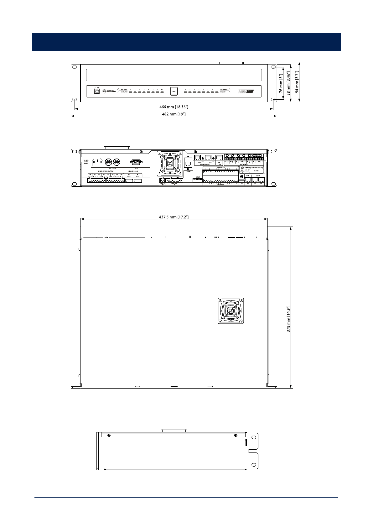
43
DIMENSIONS

44
SPECIFICATIONS
MU 7100EN MKII
System specifications
Number of zones managed: 128
Built-in power amplifier: Yes
Spare amplifier automatic change-over: Yes
Max number of consoles: 32
Number of console buses: 2
Number of simultaneous emergency audio channels: 2
Max number of units connectable: 64
Communication bus: Serial
Connection Cables: FTP CAT 5, FTP CAT 6
Integrated pre-recorded emergency messages: Yes
Integrated pre-recorded routine messages: Yes
Message scheduler: Yes
Remote monitoring: Yes
Protocols for system integration: ASCII
Amplifier specifications
Amplifier Class: D
Number of channels: 8
Power output per channel (@ 8 ohm): 80 W RMS
A/B speakers line: Yes
Frequency Response (-3dB): 20 Hz ÷ 20 kHz
Signal/noise rate (”A” weighted) >96 dB
Distortion (THD+N) @ 1 kHz nominal power: <0.05 %
Input section
Total number of inputs: 9
Balanced: 7
Mono: 7
Mic+Line inputs: 7
Mic+Line connectors: Euroblock
Paging inputs: 2
Paging connectors: RJ45
General Purpose Inputs (GPI): 8
Programmable GPI: Yes
Monitored GPI: 8
Processing
DSP: Yes
EQ Filters: Yes
Compressors: Yes
Delay: Yes
Tone controls: Yes
Controls
Configuration: DIP switch, Ethernet, PC Software
Number of programs/presets: 128

45
MU 7100EN MKII
Priority: Yes
Music on hold: Yes
Chime tone: Yes
Protections
Cooling: Convection/Forced
Short circuit: Yes
Thermal: Yes
DC: Yes
Fuses: Yes
Power requirements
Operating voltage: 90-240 V~ 50/60Hz
DC power: Yes
DC power value: 48 V
Power consumption: 980 W
Standard compliance
EN54-16 certified: Yes
CE marking: Yes
CPR number: 1438-CPR-0241
Physical specifications
Cabinet/Case Material: Metal
Rack mounting: 19", 2U
Size
Height: 94 mm / 3.7 inches
Width: 482 mm / 18.98 inches
Depth: 378 mm / 14.88 inches
Weight: 8.4 kg / 18.52 lbs

46

47

RCF S.p.A. Via Raffaello Sanzio, 13 - 42124 Reggio Emilia – Italy 10307749 A
Tel +39 0522 274 411 - Fax +39 0522 232 428 - e-mail: [email protected] - www.rcf.it

