Loading ...
Loading ...
Loading ...
4
WIRING DIAGRAMS
1101653B
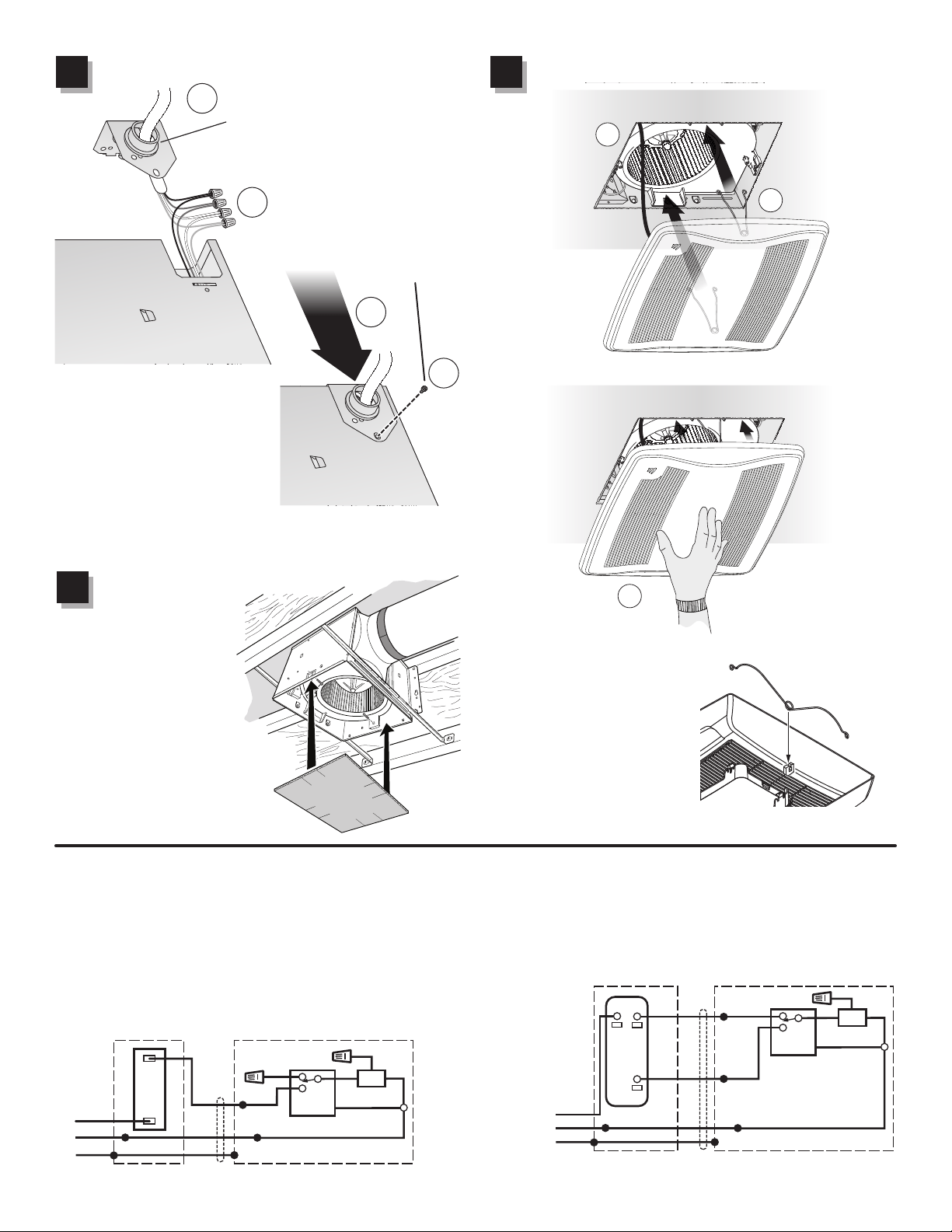
Tape mask into housing.
Mask protects unit during
construction. Remove
before attaching grille.
Install ceiling material. Cut
out around housing.
Install housing mask.
1
7
Attach grille.
1
8
If grille spring becomes
dislodged from grille - snap it
back into place as shown.
Connect wiring.
1
6
Screw from
Parts Bag
Attach cable clamp to
Knockout Plate. Knockout
Plate mounts to outside of
Housing and may be oriented
as desired.
Connect wires
3
4
Connect power cable to wiring
plate (from parts bag) using UL
approved connector. Connect
house wiring to fan wiring. Refer
to wiring diagrams for connection
details. Use screw (from parts
bag) to secure wiring plate to fan
housing. Re-install wiring panel
and secure with screw from parts bag.
1
2
1
2
3
ON / OFF SWITCH
(PURCHASE SEPARATELY)
ON / OFF
SWITCH
120
VAC
LINE
IN
SWITCH BOX
WHT
GRD
BLK
WHT
UNIT
ORG
BLK
WHT
GRD
WHT
BLK
WHT
BRN
HUMIDITY
CONTROL
FAN
RED
RED
120
VAC
LINE
IN
SWITCH BOX
WHT
GRD
WHT
UNIT
BLK
WHT
GRD
WHT
BLK
WHT
HUMIDITY
CONTROL
FAN
RED
BLK
ORG
BRN
2-FUNCTION CONTROL
(PURCHASE SEPARATELY)
COM
(1)
HUMIDITY
CONTROL
(AUTO/OFF)
(2)
FAN
(ON/OFF)
WIRING OPTION #1
• When switch is ON, fan will operate automatically,
based on room humidity conditions.
• Turn fan ON immediately for the set timer period (to
control odors), by cycling switch.
WIRING OPTION #2
• When first switch (1) is ON, fan will operate automatically based on
room humidity conditions.
• Turn fan ON
immediately
(to control
odors) by
using sec-
ond switch
(2).
Plug in sensor
Loading ...
Loading ...
Loading ...