Loading ...
Loading ...
Loading ...
25
SERVICE AND MAINTENANCE
2. Engage the bypass rods by pulling each one out (a) and to the right (b) to
lock it into place. See Figure 27.
3. Disengage the bypass rods by reversing steps a & b after moving the tractor.
See Figure 27.
NOTE: The transmission will NOT engage when the hydrostatic bypass rod is
pulled out. Return the rod to its normal position prior to operating the riding
mower.
CAUTION
Never attempt to move the riding mower manually without first opening
the hydrostatic relief valve. Doing so will result in serious damage to the
riding mower’s transmission.
Adjustments
CAUTION
Shut the engine off, remove the ignition key and engage the parking brake
before making adjustments. Protect your hands by using heavy gloves
when handling the blades.
Adjusting RH & LH Drive Control Levers
The RH and LH drive control levers can be adjusted up or down and forward or
backward for the comfort of the operator. The drive control levers can be placed in
either of two height positions, and/or can be moved forward or rearward within the
range of the slot in each lower arm.
To adjust the drive control lever height, proceed as follows:
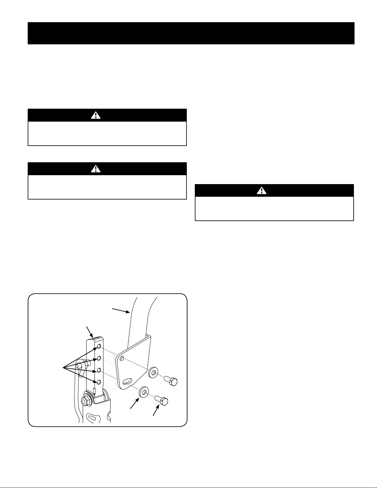
1. Remove the upper hex screw and flat washer securing the lever to the pivot
bracket.
2. While supporting the control lever to keep it from falling, remove the hex
screw and flat washer from the bottom of the control lever and lower arm.
Refer to Figure 28.
Flat Washer
Hex Screw
Lower Arm
Control Lever
Height
Adjustment
Holes
Figure 28
3. Reposition the control lever to align with the other set of holes in the lower
arm and insert the hex screw through the flat washer and into the lower
arm. Tighten the hex screw until snug.
4. Insert the hex screw through the flat washer and through the control lever
slot and the lower arm. Do not tighten now.
5. If you are going to adjust the control levers forward or rearward, proceed to
the next step. If not, fully tighten the hex screw.
To adjust the drive control levers forward/rearward, proceed as follows:
1. If not already loose, loosen the hex screw and rotate the control lever either
forward or rearward to the desired position. See Figure 28.
NOTE: If the control lever is too tight to move, slightly loosen the hex screw
at the bottom of the control lever.
2. Tighten the hex screw to fix the control lever in the adjusted position
3. Repeat the above procedure to adjust the other control lever into the same
position. Adjust so that both levers are even with each other when in the
neutral position.
Deck Leveling
NOTE: Check the tractor’s tire pressure before performing any deck leveling
adjustments. Refer to Tires for information regarding tire pressure.
WARNING
Shut the engine off, remove the ignition key and engage the parking brake
before making adjustments. Protect your hands by using heavy gloves
when handling the blades.
Leveling the Deck (Side-to-side)
NOTE: Check the tractor’s tire pressure before performing any deck leveling
adjustments. Refer to Tires for information regarding tire pressure. Always level the
deck side-to-side before front to rear.
If the cutting deck appears to be mowing unevenly, a side-to-side adjustment can
be performed. Adjust if necessary as follows:
1. With the tractor parked on a firm, level surface, place the deck lift handle in
a middle mowing position and rotate both outside blades so that they are
perpendicular with the tractor.
2. Measure the distance from the outside of the left blade tip to the ground
and the distance from the outside of the right blade tip to the ground. Both
measurements taken should be equal. If they’re not, proceed to the next step.
Loading ...
Loading ...
Loading ...