HEATIZON.COM
Installation & Operating
Manual
Warranty Registration
RADIANT HEATING SYSTEMS
• SNOW MELTING
• FLOOR WARMING
• SPACE HEATING
• ROOF DEICING
• GUTTER DEICING
06/2018
HEATIZON.COM
2
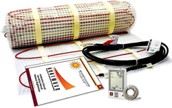
The Heatwave® Heating Cable comes in pre-established lengths that have been designed to deliver a
specified heat density. Therefore, it is essential that all of the Heatwave® Heating Element contained
in the kit be installed.
Do not cut or alter the red heating cable in any way
.
In order to minimize the risk of damage to the Heatwave® Heating Cable, Heatizon Systems
recommends that the Heatwave® Cable be installed immediately prior to the installation of the
cementitious material that goes over it.
Never cross the Heatwave® Heating Cable over itself, the in-floor sensor wire, or any other conductor
or wire.
When installing Heatizon Systems products, strict compliance with the National Electrical Code, local
Building Codes, and Heatizon’s Installation Manual is essential.
It is highly recommend to take photographs to document the installed Heatwave® for future
reference before installing the flooring.
Heatizon Systems is glad to offer product
phone support for the Heatwave product. It is
VERY important to have read this manual first.
Please have your resistance test numbers and
system model name/number available BEFORE
calling for technical support.
HEATIZON.COM
3
GENERAL INFORMATION 4
WARNINGS 6
1. GENERAL GUIDELINES 6
1.1 Use of the Manual 6
1.2 Safety Guidelines 6
1.3 Remember to Measure Resistance 8
1.4 Limited Lifetime Warranty 8
2. HEATWAVE® SYSTEM 8
2.1 Heatwave Specifications 8
2.2 Sample Thermostat Specifications 8
2.3 Heatwave® typical installations and applications 9
3. FLOOR HEATING INSTALLATION DESIGN 10
3.1 Design the Installation 10
4. PRODUCT SELECTION—MAT OR CABLE 12
4.1 Heatwave® Mat Selection 12
4.2 Heatwave® Cable Selection 13
Cable Calculations 13
5 INSTALLATION 14
5.1 Installation Procedures 14
5.2 Heatwave® Mat Installation 16
Heatwave® Mat Layout Configurations 17
5.3 Heatwave® Cable Installation 18
6. COMPLETING INSTALLATION 19
6.1 MEASURE THE RESISTANCE (TEST #3) 20
6.2 INSTALL FLOOR COVERING 20
6.3 CONNECT POWER SUPPLY AND THERMOSTAT 20
6.4 MEASURE THE RESISTANCE (TEST #4) 20
6.5 RECORD INFORMATION AND AFFIX LABELS 20
6.6 ENJOY THE COMFORT OF HEATWAVE 20
7. COMMISSIONING 21
7.1 INSULATION RESISTANCE TEST 21
7.2 HEATING CABLE RESISTANCE TEST 21
7.3 SENSOR RESISTANCE TEST 21
8. THERMOSTAT QUICK START 22
8.1 SET TIME AND DAY 22
8.2 HOME SCREEN 22
8.3 SCHEDULE SELECT 22
8.4 PROGRAM SELECT 23
8.5 MODE SELECT 23
8.6 OTHER SETTINGS 23
9. TROUBLESHOOTING 24
10. FAQS 25
ELECTRICAL ROUGH-IN 26
THERMOSTAT WIRING 27
LAYOUT GRID 28
HEATWAVE® WARRANTY 29
HEATWAVE® REGISTRATION FORM 31
Distributed by:
Heatizon Systems
4137 South 500 West
Murray, UT 84123
Phone: (801) 293-1232
Fax: (801) 293-3077
heatizon.com
HEATIZON.COM
4
General Information
The instructions in this manual must be followed when preparing and installing the
Heatwave® Cable or Mat Floor Warming System. This manual and the installation layout
should be made available to all contractors and installers working on the job. Both
should then be turned over to the building owner after the installation is complete.
Temperature and Time Control
For optimal control of the Heatwave® floor warming system, contact a Heatizon Systems
distributor for a variety of floor sensing thermostat options.
Maintenance
The Heatwave® floor warming system has no moving parts and is virtually maintenance-free. The
GFCI (Ground Fault Circuit Interrupter), internal to the thermostat if Heatizon Systems supplied it,
should be tested monthly as described in the manufacturer’s pamphlet to ensure its continued
safe operation. If an external GFCI is utilized instead, it should be tested monthly.
Subfloors
Heatwave® may be installed over any well insulated subfloor (i.e. plywood, concrete, or
underlayment material) prepared in accordance with the most recent TCA (Tile Council of America)
guidelines.
Floor Coverings
Heatwave® will be most effective if installed under rigid floors that are naturally good conductors
of heat such as ceramic tile, marble, and other stone floorings. There are additional requirements
for applications that utilize different floor coverings. For heating wall-to-wall carpeting,
parquet, laminate or engineered wood floors and vinyl or linoleum flooring, a thicker heatsink
bed is recommended for floating applications and glued down floor. A 1” to 1.5” spacing is
recommended between the heating cable and the surface of the floor.
Insulation
Heatwave® will be most effective and efficient if installed over well-insulated areas. Insulation will
minimize heat loss into the subfloor (i.e. concrete slab), allowing the heat to transfer to the surface
more quickly.
FAILURE TO FOLLOW THE INSTRUCTIONS IN THIS MANUAL MAY
VOID THE WARRANTY ON THE FLOOR WARMING SYSTEM.
NOTE:
HEATIZON.COM
5
Planning the Installation
Before laying the Heatwave® Cable or Mat Floor Warming System, review the installation
layout and verify that all dimensions match the need of the project. The installation plan
should include the following:
1. Placement, direction, and dimensions of the Heatwave® Cable or Mat.
2. The starting and ending points of each Heating Cable length or Mat size.
3. The location of the thermostat or other suitable activation.
4. The location of the floor sensor between two heating cables.
REMEMBER! The installation plan
*
for each area should be attached to this manual and be
provided to the building owner when the installation is complete.
Installation Considerations
* It is recommended that photographs be taken to document the installation of the layout.
DO
1. Completely inspect the Heatwave® System
immediately upon its arrival and report
any damage to Heatizon Systems and the
delivery party.
2. Clean the floor of all debris before placing
the mat/cable on the floor.
3. Make sure there are no protruding objects
(nails, staples, etc.) on the subfloor that could
damage the heating element.
4. Walk over the unprotected Cable/Mat with
rubber soled shoes.
5. Measure and record Cable/Mat resistance
according to the instructions.
6. Use Cables/Mats connected to the same
controller or used in the same room or area,
that have the same heat output. i.e. ALL
Cables/Mats should be EITHER 10 watts/sq.
ft. OR ALL 15 watts/sq. ft.
7. Make sure all components of the system are
rated for the same Voltage (120V OR 240V).
8. Have all electrical work completed by a
professional electrician in accordance with all
local and national codes and regulations.
9. Call our Technical Support Hot line at
888-239-1232, for answers to installation
questions, help solving a problem, or believe
that the Heatwave® system was cut or
damaged during installation.
DON’T
1. DON’T shorten the spacing in the Mat.
2. DON’T cut the red heating wire.
3. DON’T drop or bang any tools (i.e. trowel)
on or hit the heating wires with any sharp
objects.
4. DON’T install any fasteners such as nails,
screws, etc. through any area covered by the
Heatwave® Cable/Mat.
5. DON’T install Heatwave® under cabinets,
built-in appliances, etc. to avoid excessive
heat from building up in those areas.
6. DON’T install Cables/Mats over expansion
joints.
7. DON’T install Heatwave® in walls.
8. DON’T overlap Cables/Mats or allow any
wires to cross or touch each other.
9. DON’T crimp the heating wire while
customizing the mat
10. DON’T place high/thick insulating objects
over the heated area to avoid excessive
build-up of heat in these areas.
11. DON’T forget to install the floor sensor.
12. DON’T attempt to repair cut or damaged
heating wire without contacting Heatizon
Systems first 888-239-1232.
13. DON’T install the Heatwave® system within
6” of a wax toliet gasket.
HEATIZON.COM
6
Important Safeguards and Warnings
WARNING: Shock and fire hazard
• If the Heatwave® System is damaged or not installed properly, fire or shock could occur
resulting in serious personal injuries or damage to property. Carefully follow the warnings and
instructions contained in this manual.
• It is important that this equipment is installed only by qualified persons who are familiar with
the proper sizing, installation, construction and operation of floor warming systems and the
hazards involved.
• The installation must comply with all national and local electrical codes. Consult the authority
in the jurisdiction familiar with these requirements, either the NEC (National Electric Code),
CSA (Canadian Standard Assocation) should there be any questions.
• The Heatwave® System is designed for under floor heating purposes only. Be sure that the
floor is not penetrated by nails, screws, or similar devices that can cause damage during and
after installation or during subsequent or future floor work.
• If the Heatwave® System is damaged, it must be replaced or repaired. To repair or to splice
any part of the system, use only Heatizon Heatwave® Repair Kit (part number HWRPKIT).
1. General Guidelines
1.1 Use of the Manual
This manual describes the Heatwave® Mat and Cable floor heating system — how to design
the room, select the product, and install the system. It is important to thoroughly review this
manual and the Thermostat Installation and Operation Manual prior to installation:
For additional information regarding any aspect of the Heatwave® System, contact:
Heatizon Systems
4137 South 500 West
Murray, UT 84123 USA
Tel: 888-239-1232
Tel: 801-293-1232
Fax: 801-293-3077
heatizon.com
1.2 Safety Guidelines
The safety and reliability of any floor heating system depends on proper design, installation,
and testing. Incorrect installation or mishandling of the product can cause damage to the
heating cable, system components and property, and can create a risk of fire or shock. The
guidelines and instructions contained in this guide are important. Follow them carefully to
minimize these risks and to ensure that the Heatwave® System performs as designed.
Pay special attention to the following:
• Instructions Marked: • Safety Warnings:
NOTE:

DO NOT CUT
THE RED CABLE!
The HEATWAVE Mat/Cable systems are engineered to achieve
specific heat output for the square footage to which they are
designed. Cutting the red cable to fit a space is extremely
dangerous and can result in a fire. Do not cut the red cable to
avoid an obstacle or fixture, use other methods as described
in this manual. Make sure to avoid damaging/cutting the red
cable during/after the installation of the flooring material by
being aware of all red cable locations.
Consult the TROUBLESHOOTING section of the installation manual in the event that the cable is damaged or cut by accident.
HEATIZON.COM
8
1.3 Remember to Measure Resistance
The resistance between the two conductor wires should be measured. Compare this
resistance reading to the “Total Ohms” column in Product section 4.1 for Heatwave®
Mats, and section 4.2 for Heatwave® Cables. The value should be within ±10%. Also
measure the resistance between each of the two conductors and the shielding/ground wire.
Both should read infinity or open. If there is a different than expected readings for any of these
measurements are observed, contact Heatizon Systems at 888-239-1232. Please refer to Section 7
(Commissioning) for instructions on how to measure the resistance.
1.4 Limited Lifetime Warranty
For the life of the floor covering and while in possession of the original owner, Heatizon warrants
that the Heatwave® heating cable is free from defects in material, design and workmanship. The
warranty is only valid if the warranty certificate has been properly completed, and the installation
is in accordance with the installation instructions.
2. Heatwave® System
2.1 Heatwave Specifications
MATS CABLES
Cable Construction
Twin Conductor Twin Conductor
Rated Voltage
120V, 240V 120V, 240V
Output
12W/ft2 (130W/m2) ± 10% 2.73 to 4.36W.ft (8.66 to 14.30W/m) ± 10%
Cable Spacing
3” (76.2mm) 2.5” to 4.5” (64.5mm to 114.3mm)
Cable Diameter
1/8” to 1/6” (3.2mm to 4.2mm) 1/8” to 1/6” (3.2mm to 4.2mm)
Conductor Insulation
Fluoropolymer Fluoropolymer
Outer Insulation
Fluoropolymer or TPE Fluoropolymer or TPE
Max. Ambient Temp.
85°F (30°C) 85°F (30°C)
Min Installation Temp
40°F (5°C) 40°F (5°C)
Cold Lead
2-wire heating conductor plus
ground braid; 15 ft (4.57 M)
2-wire heating conductor plus ground
braid; 15 ft (4.57 M)
Cable Construction
On/Off Control
Rated Voltage
120/240V ± 15%, 50/60 Hz
Output
15 AMP
Cable Spacing
40° to 104°F (5° to 40°C)
Cable Diameter
32° to 104°F (0° to 40°C)
Conductor Insulation
2-wire, 10 foot lead wire
2.2 Sample Thermostat Specifications
Important: measure the resistance four times during the installation process
Remember to always measure, verify and record the actual resistance throughout the
installation process (out of the box, after installation, after covering with cementitious
material, and after installation of floor covering).
NOTE:
HEATIZON.COM
9
Alternative method: self-leveling cement is recommended for large surfaces and the following
floor materials: engineered wood, laminate, floating floors, vinyl, linoleum and
carpet.
2.3 Heatwave® typical installations and applications
Consult the manufacturer for information on special installation
requirements for carpets, wood, laminate and vinyl or linoleum flooring.
• Read the instructions carefully before installing Heatwave® system.
• Remember to measure the resistance four times.
• Do not install Heatwave® in walls or ceilings.
• The cable must be embedded in cementitious material.
• The minimum installation temperature is 40ºF (5°C ).
• The heating cable cannot be cut to length, crossed over itself, or installed too close to itself.
• Use copper conductor feeder wire only.
• Remember to check that the supply voltage matches the voltage of the Heatwave.
• Remember to place the labels as written in this instruction.
• Only for indoor installation.
• Metal structures or materials used for the support of or on which the Heatwave® is installed
must be grounded in accordance with applicable CSA or NEC requirements.
Please consult Heatizon Systems for any other questions.
NOTE:
HEATIZON.COM
10
Important:
Operating the 240V cable at 208V reduces the power output to approximately
9W/sq.ft. (25% reduction)
NOTE:
3. Floor Heating Installation Design
3.1 Design the Installation
3.1.1 Measure the heated area
Determine the heated area of the floor where there are no permanent fixtures or
furniture such as showers, toilets, vanities, or cabinets. Measure the heated area of the floor.
For example, if the area of the bathroom is 96 ft
2
, but when the area of the vanity, shower and
toilet is subtracted, the total heated area is only 74 ft
2
.
3.1.2 Determine the power supply voltage
The available supply voltages include 120V, 208V or 240V.
HEATIZON.COM
11
Important:
The predetermined Heatwave® spacing must be maintained to ensure proper floor
heating. To avoid cold areas on the floor, do not change the Heatwave® heating
cable spacing when laying out the Mat or Cable.
NOTE:
3.1.3 Plan the design
Determine the optimum Heatwave® Cable or Mat layout for the heated area to ensure
coverage. Select a spot for the thermostat in the wall above the heated area where it
can be reached by the ten foot cold lead on the Heatwave, and the length of the floor
temperature sensor.
HEATIZON.COM
12
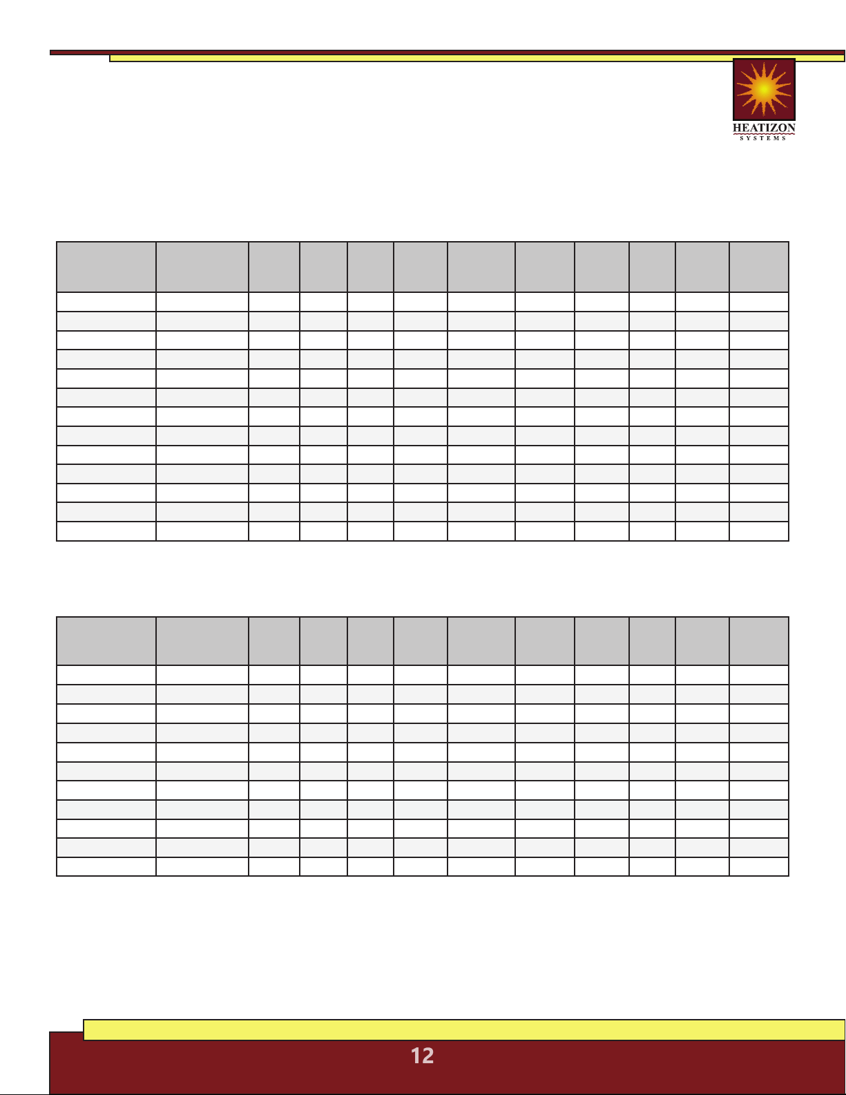
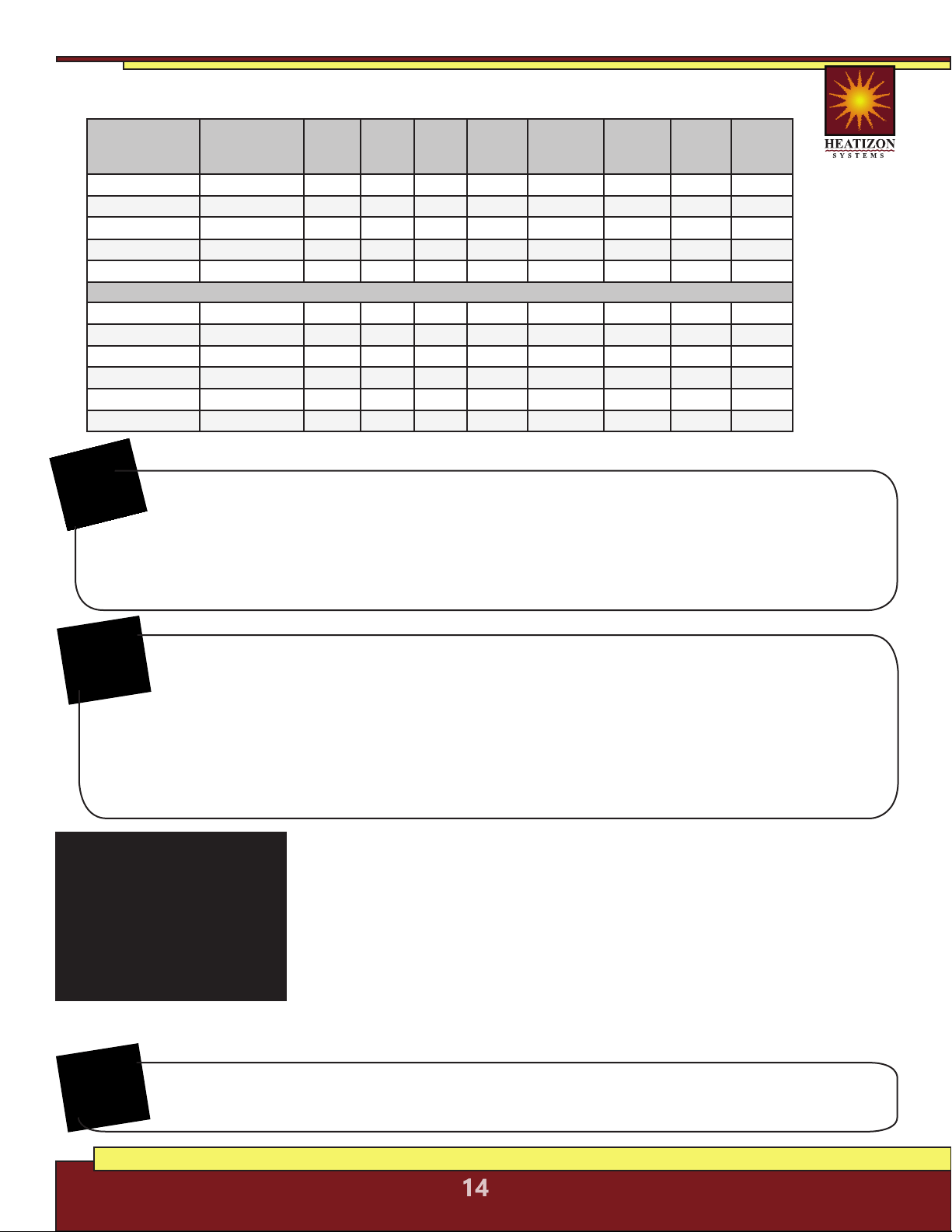
4. Product Selection—Select Either Heatwave® Mat
or Heatwave® Cable
4.1 Heatwave® Mat Selection
Confirm that Heatwave® product is no larger than the heated area. Following the
example from Figure 3, if the heated area is 74 ft
2
, select the 70 ft
2
Heatwave®
Heating Mat.
Heatwave® Mats, 12 Watts/Ft
2
, 120 VAC
Heatizon Part
Number
Manufacturer
Number
Total
Watts
Total
Ohms
Amp
Load
Watts/
Foot
Coverage
Area/Square
Foot
Watts/
Square
Foot
Mat
Length
Mat
Width
Cable
spacing
(O.C.)
14AWG
Cold Lead
Length
HW2012-100 HW2012-10 120 120.0 1.0 2.73 10 12.00 6.1’ 20” 2.90” 15’
HW2012-150 HW2012-15 180 80.0 1.5 3.59 15 12.00 9.1’ 20” 3.81” 15’
HW2012-200 HW2012-20 240 60.0 2.0 3.13 20 12.00 12.2’ 20” 3.33” 15’
HW2012-250 HW2012-25 300 48.0 2.5 2.63 25 12.00 15.2’ 20” 2.79” 15’
HW2012-300 HW2012-30 360 40.0 3.0 2.55 30 12.00 18.3 20” 2.71” 15’
HW2012-350 HW2012-35 420 34.3 3.5 3.47 35 12.00 21.3 20” 3.69” 15’
HW2012-400 HW2012-40 480 30.0 4.0 3.12 40 12.00 24.4 20” 3.31” 15’
HW2012-500 HW2012-50 600 24.0 5.0 3.20 50 12.00 30.5 20” 3.40” 15’
HW2012-600 HW2012-60 720 20.0 6.0 3.40 60 12.00 36.6 20” 3.61” 15’
HW2012-700 HW2012-70 840 17.1 7.0 2.93 70 12.00 42.7 20” 3.11” 15’
HW2012-800 HW2012-80 960 15.0 8.0 2.65 80 12.00 48.8 20” 2.82” 15’
HW2012-900 HW2012-90 1080 13.3 9.0 3.36 90 12.00 54.9’ 20” 3.56” 15’
HW2012-1000 HW2012-100 1200 12.0 10.0 4.15 100 12.00 61.0’ 20” 4.44” 15’
Heatwave® Mats, 12 Watts/Ft
2
, 240 VAC
Heatizon Part
Number
Manufacturer
Number
Total
Watts
Total
Ohms
Amp
Load
Watts/
Foot
Coverage
Area/Square
Foot
Watts/
Square
Foot
Mat
Length
Mat
Width
Cable
spacing
(O.C.)
14AWG
Cold Lead
Length
HW2012-400B HW2024-40 480 120.0 2.0 3.13 40 12.00 24.4’ 20” 3.33” 15’
HW2012-500B HW2024-50 600 96.0 2.5 2.63 50 12.00 30.5’ 20” 2.79” 15’
HW2012-600B HW2024-60 720 80.0 3.0 2.55 60 12.00 36.6’ 20” 2.71” 15’
HW2012-700B HW2024-70 840 68.6 3.5 2.39 70 12.00 42.7’ 20” 2.54” 15’
HW2012-800B HW2024-80 960 60.0 4.0 3.12 80 12.00 48.8’ 20” 3.31” 15’
HW2012-900B HW2024-90 1080 53.3 4.5 2.59 90 12.00 54.9’ 20” 2.75” 15’
HW2012-1000B HW2024-100 1200 48.0 5.0 3.20 100 12.00 61.0’ 20” 3.40” 15’
HW2012-1100B HW2024-110 1320 43.6 5.5 2.86 110 12.00 67.1’ 20” 3.03” 15’
HW2012-1200B HW2024-120 1440 40.0 6.0 3.40 120 12.00 73.2’ 20” 3.61” 15’
HW2012-1450B HW2024-145 1740 33.1 7.3 3.14 145 12.00 88.4’ 20” 3.33” 15’
HW2012-1600B HW2024-160 1920 30.0 8.0 2.65 160 12.00 97.6’ 20” 2.82” 15’
HEATIZON.COM
13
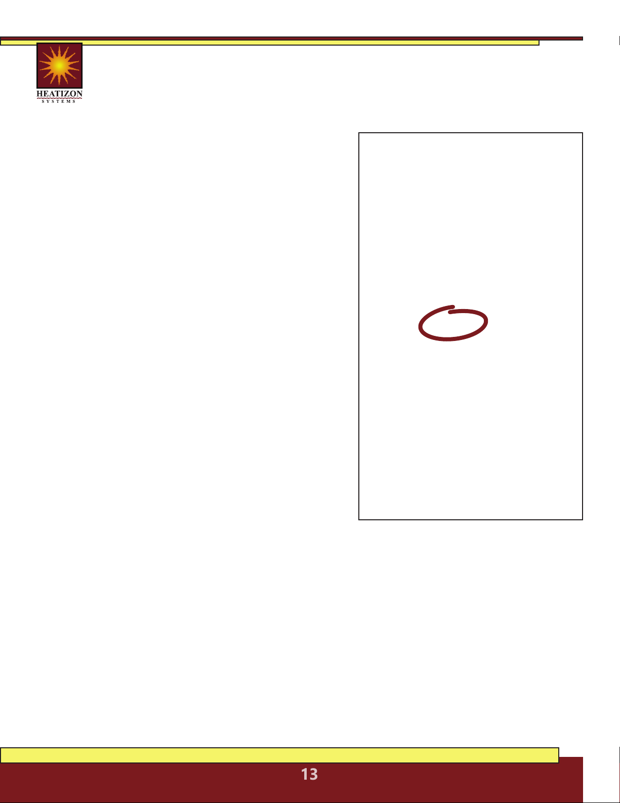
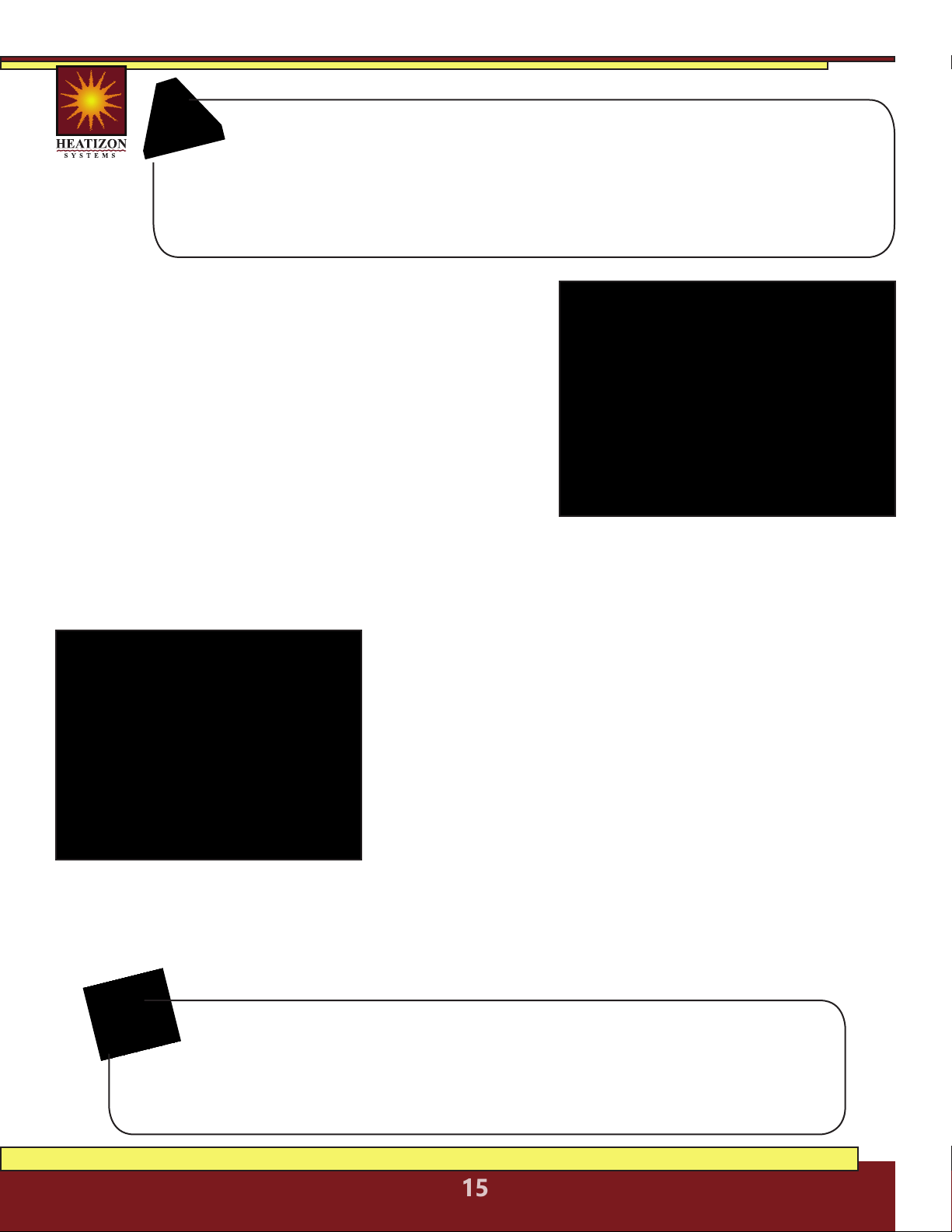
4.2 Heatwave® Cable Selection
The Heatwave® Heating Cable comes in pre-established lengths that have been
designed to deliver a specified watt density. To ensure that the Heatwave® Heating
Element length purchased is the correct size for the project, complete this simple
worksheet prior to beginning the installation process.
STEP 1:
STEP 2:
STEP 3:
STEP 4:
STEP 5:
STEP 6:
Calculate Square Footage to be Heated.
Determine the square footage of the area to
be warmed. Note: this is not necessarily the
same as the room dimensions. Enter the total
square footage on line A.
Determine Watts Per Square Foot.
Determine the Watts per square foot for the
application. Heatizon Systems suggests the
following Watts per square foot:
• Floor Warming—8 to 15 Watts per square
foot
• Space Heating—Watts per square foot
and spacing between element runs should
be determined by a heat loss calculation.
Contact Heatizon Systems for information on
how to obtain a heat loss calculation. Enter the
desired total Watts per square foot on Line B.
Calculate Total Watts. Calculate total Watts
by multiplying Line A by Line B, and enter the
result on Line C.
Determine Input Voltage. Determine if the
Heatwave® Heating Cable will be powered
by 120VAC or 240VAC, and check the correct
input voltage on Line D.
Select the Correct Heatwave® Heating Cable Length. Use the table (pg 12) to select
the Heatwave® Heating Cable Model that is the correct input Voltage from line D, and
will deliver the closest total watts calculated on Line C. Heatizon Systems recommends
selecting the next larger Heatwave® Heating Cable Length if the total Watts calculated
in Step 3 is between two models. Select the model number, and write the corresponding
Element “Cable Length” on Line E.
Calculate Element Spacing. Calculate the amount of space between the runs of
element for the application and the Heatwave® Heating Element.
CALCULATIONS
*
Line A: ____________________
(Square Footage)
Line B: ____________________
(Watts Per Square Foot)
Line C: ____________________
(Total Watts)
Line D: 120VAC 240VAC
(Circle One)
Line E: ____________________
(Element Length)
_________________ ÷ _________________
Square Footage Element Length
From Line A From Line E
Result from above times 12 =
Line F: ____________________
(Element Spacing)
* Figures shown are for illustrative purposes only.
74
12
203
203
4.374
74
HEATIZON.COM
14
5. INSTALLATION
Follow these steps to ensure a successful Heatwave®
installation.
5.1.1 PLAN THE LAYOUT
Using the back page of this manual, make a sketch layout or a floor
plan of the room; include all permanent furnishings such as toilets,
bathtubs, appliances, cabinetry, etc. Indicate all dimensions required to
determine the available floor area and the position of the thermostat.
Important: Tools and materials required
The following items may be required to install and test the floor heating system:
• Scissors • Tape measure • Hot glue gun • Utility knife
• Screwdriver • Tin snips • Wire strippers • Multimeter
• Heatizon Plastic Cable Clips or Cable Strap
Heatizon recommends that the installation be documented with photos and drawings
to note the location of connections and the sensor, as well as the cable layout.
NOTE:
Heatwave® Cables, 120/240 VAC
Heatizon Part
Number
120V Input
Manufacturer
Number
Total
Watts
Total
Ohms
Amp
Load
Watts/
Foot
Coverage
Area/Square
Foot
Watts/
Square
Foot
Cable
Length
Cable
spacing
(O.C.)
HWC-815 HWC2012-44 120 120.0 1.0 2.73 8-15 14-8 44’ 2.5-4.5”
HWC-1630 HWC2012-77 240 60.0 2.0 3.12 16-30 14-8 77’ 2.5-4.5”
HWC-3260 HWC2012-154 480 30.0 4.0 3.12 32-60 14-8 154’ 2.5-4.5”
HWC-5094 HWC2012-203 750 19.2 6.3 3.69 50-94 14-8 203’ 2.5-4.5”
HWC-64120 HWC2012-362 960 15.0 8.0 2.65 64-120 14-8 362’ 2.5-4.5”
240V Input
HWC-1631B HWC2024-86 245 235.1 1.0 2.85 16-31 14-8 86’ 2.5-4.5”
HWC-3260B HWC2024-110 480 120.0 2.0 4.36 32-60 14-8 110’ 2.5-4.5”
HWC-56105B HWC2024-242 840 68.6 3.5 3.47 56-105 14-8 242’ 2.5-4.5”
HWC-80150B HWC2024-375 1200 48.0 5.0 3.20 80-150 14-8 375’ 2.5-4.5”
HWC-114214B HWC2024-564 1710 33.7 7.1 3.03 114-214 14-8 564’ 2.5-4.5”
HWC-128239B HWC2024-726 1915 30.1 8.0 2.64 128-239 14-8 726’ 2.5-4.5”
Before Laying the Heatwave® Mat or Cable
Note: Measure the resistance between each conductor and the shielding/ground
wire. Both should read infinity. Always complete a Heatizon Systems “Resistance in
OHMS Form” (see form in the back of this manual) out of the box, immediately following
the installation of the Heatwave® Heating Cable/Mat, immediately prior to covering the
Heatwave® Heating Cable/Mat, and again just prior to energizing the Heatwave® Heating
Cable/Mat.
NOTE:
HEATIZON.COM
15
Important: Mark the position of the connection point between the power
lead and the red Heatwave® heating cable. This connection must be
embedded in cementitious material. When using a floor temperature
sensing thermostat, mark the sensor position in the middle of two heating
cables, about 10 in. (25 cm) away from the wall (within the heated area), as
close as possible to the thermostat.
5.1.2 TRANSFER LAYOUT TO FLOOR
Draw an outline of the layout on the room floor including
a foot print of all furnishings that are not yet installed.
Unroll the first few feet of the Heatwave® Mat or Cable.
The starting point of the cable must be placed within 15
ft. of the thermostat.
5.1.3 INSTALL SENSOR
If using a floor temperature sensing thermostat,install
the sensor now, either in conduit tube, or directly to the
subfloor. The sensor and/or tube needs to be installed
between the thermostat wall box and the sensor position. The conduit tube must be partially
countersunk into the subfloor. Cut a channel in the floor to a location below the thermostat for
the sensor conduit. The conduit has to go from the wall below the thermostat and minimum of
10” away from the wall towards the middle of the floor for placement between two runs of cable.
5.1.4 PREPARE SUBFLOOR SURFACE
Clean and vacuum the floor thoroughly and remove dust and
debris from the floor that may damage the heating cable.
Ensure that the subfloor is secure and stable. Carefully fill in
all cracks to prevent any potential damage to the new tiles
resulting from shifts in the subfloor.
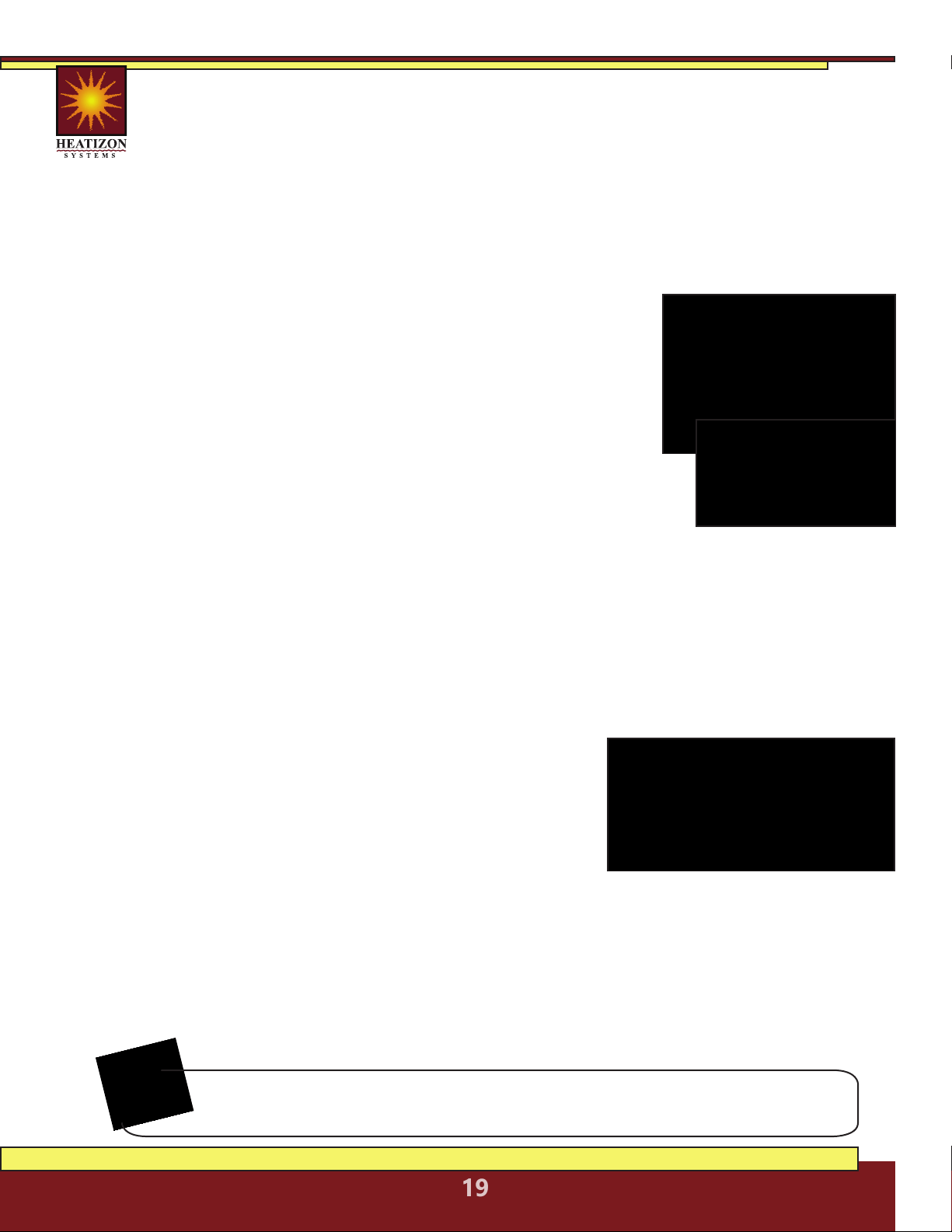
5.1.5 MEASURE THE RESISTANCE (TEST #1)
Use a digital Ohm meter to measure the resistance of the
Heatwave® Mat/Cable and compare it to the total Ohms
in the tables in Section 4.1 for Mats or in Section 4.2 for
Cables. Record the measured resistance on the Registration Form. Documenting the resistance at
each stage of installation is required for warranty purposes. Also, measure the resistance between
each conductor and the shielding/ground wire. Both should read infinity or open. Please refer to
Section 7 (Commissioning) for instructions on how to measure the resistance.
NEVER CUT OR SHORTEN THE RED HEATING CABLE!
DO NOT STAPLE THE RED HEATWAVE® HEATING CABLE. STAPLE ONLY
THE WEBBING ON HEATWAVE® MATS WHERE NO CABLE IS LOCATED!
NEVER PLACE RED CABLE WITHIN 6” OF A WAX TOILET RING.
HEATIZON.COM
16
For installing
HEATWAVE® MATS,
continue with the installation
below beginning with section 5.2.
For installing
HEATWAVE® CABLES,
skip to Section 5.3 to continue
with the installation.
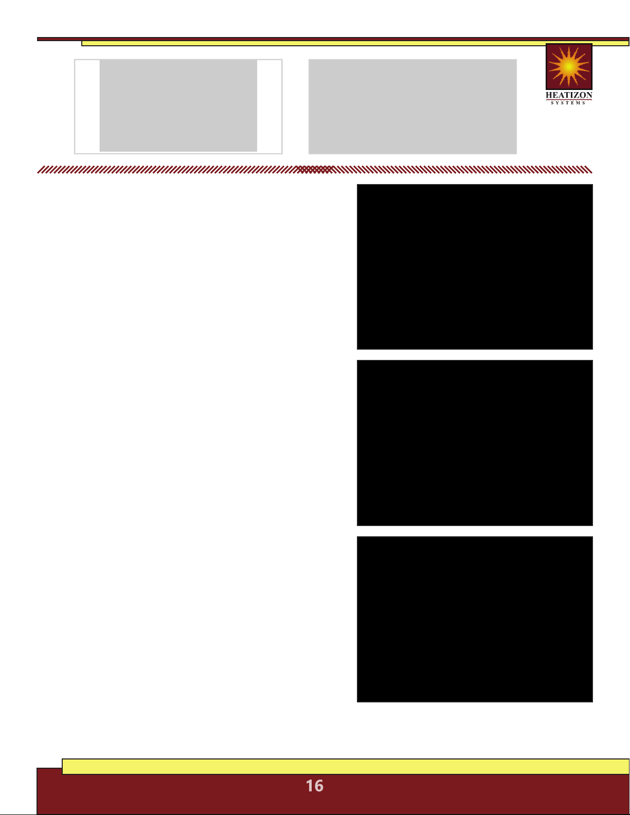
5.2 Heatwave® Mat Installation
5.2.1 Start by placing the mat such that the connection
point and the temperature sensor are in their intended
final positions and bring the power cable to the
thermostat or connection box. Ensure the connection
between the heating cable and cold lead will be
properly embedded in thinset and/or mortar. Begin
unrolling the Heatwave® Mat evenly across the floor
outside the areas that were marked previously. When
the next wall is reached, cut the mesh (being careful not
to cut the red heating cable), turn the mat, and begin
rolling in the desired direction. See Heatwave® Mat
Layout Configurations on Page 17.
5.2.2 Ensure that the Heatwave® is in full contact with
the subfloor at all times. Avoid walking on the heating
mat. If this is not possible, use shoes with very soft
rubber soles. When approaching obstacles (toilets,
cabinets, etc.), carefully remove some of the red heating
cable from the mat and lead the cable around the
obstacle. In some cases pieces of the mesh will be cut
away entirely. DO NOT CUT THE RED HEATING CABLE.
5.2.3 Use Heatizon Plastic Cable Clips, hot glue*, or a
thin strip of tape to secure the loose cable to the floor.
* Do not place hot glue gun tip directly on heating cable.
5.2.4 MEASURE THE RESISTANCE (TEST #2)
Use a digital Ohm meter to measure the resistance of
the Heatwave® Mat/Cable and compare it to the total
Ohms in the tables in Section 4.1 for Mats or in Section
4.2 for Cables. Record the measured resistance on the
Registration Form. Documenting the resistance at each
stage of installation is required for warranty purposes.
Also, measure the resistance between each conductor
and the shielding/ground wire. Both should read infinity. Please refer to
Section 7 (Commissioning) for instructions on how to measure the resistance.

HEATIZON.COM
17
Heatwave® Mat Layout Configurations
HEATIZON.COM
18
Verify the correct Heatwave® Cable has been
purchased to heat the area selected and that the
correct spacing has been determined for the area being
heated, the Watts to be delivered, and the size of system
purchased. DO NOT CUT THE RED HEATING CABLE to fit an
area. See the Tables in Section 4.2.
5.3.1 Plan room layout using tape measure, marking pencil,
and chalk line. Lay out perimeter of area to be heated first,
keeping a minimum of 1.5 inches from walls and or cabinets
and the first run of element. Once the layout is complete,
roll out the Heatwave® Heating Cable, making sure that
both ends of the heating element (where the Heatwave®
Heating Cable is pre-connected to the Cold Lead segment)
are within 15 vertical and horizontal feet of the power
switching thermostat location to accommodate Cold Lead length.
5.3.2 Tie off one Cold Lead at the location where the
power switching thermostat will be located. Continue
by laying out Heatwave® Heating Cable on the
predetermined layout, and fasten with plastic clips as
described below for the floor surface.
5.3.3 When anchoring the Heatwave® Heating Cable to
wood subfloors use either the Plastic Clips (Heatizon Part
#PLASCLIPKIT) or Heatwave® Cable Strap (Heatizon Part
#HWCSTRAP33).
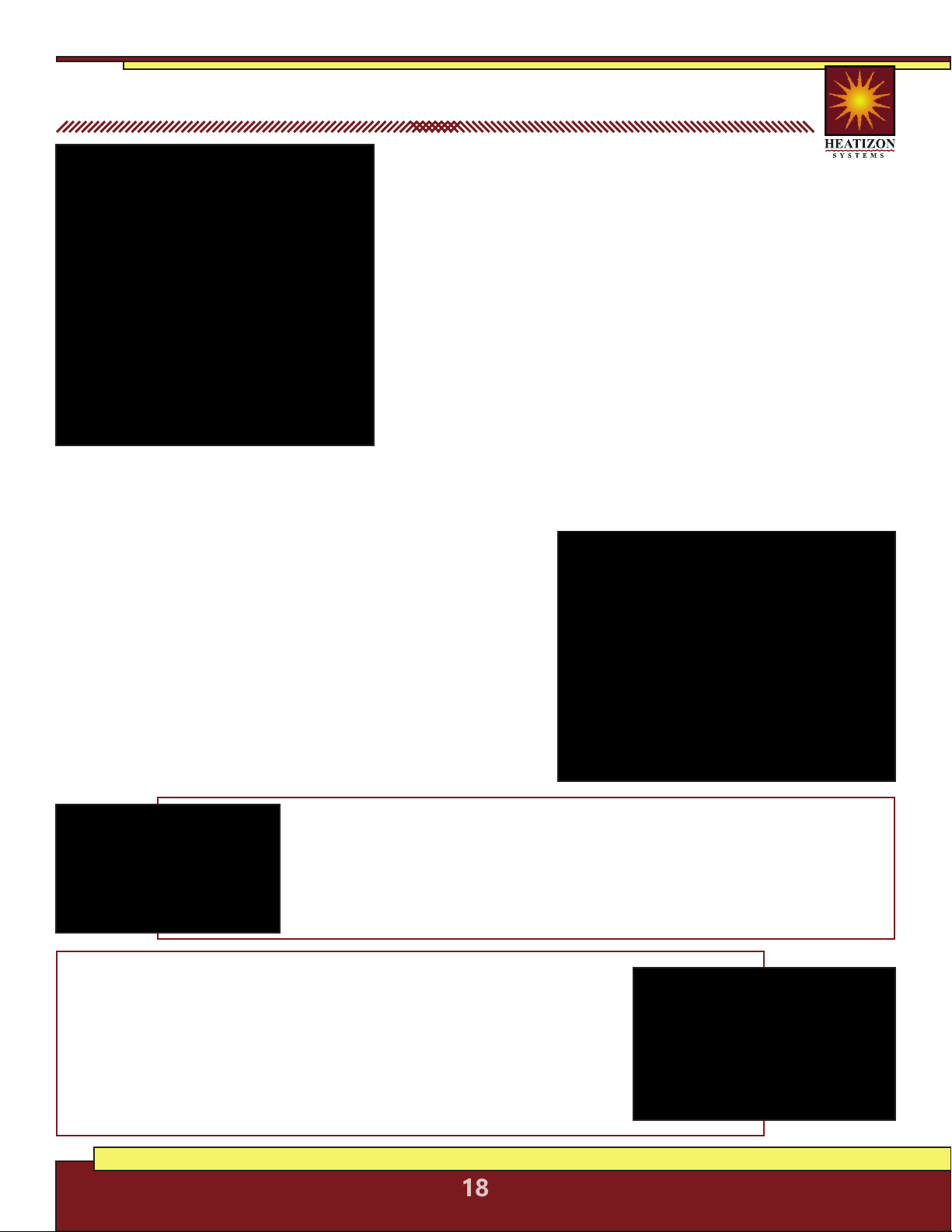
5.3 Heatwave® Cable Installation
Plastic Clips: Each 90 degree bend and each 180 degree turn requires two Heatizon
Plastic Clips. Heatizon Plastic Clips should be spaced approximately every 24 inches
along the length of the Heating cable. Heatizon Plastic Clips can be inserted around
Heatwave® Heating Cable, and secured to sub floor by hammering nail or driving a
screw through anchor ends until both plastic tails are flat against sub floor surface.
Repeat with each Heatizon Plastic Clip until all clips are secure.
Cable Strap: Heatwave® Cable Strap is used to hold Heatwave® Cables in
place on the sub floor surface at the spacing required. Variable spacing options
can be maintained using this thin metal strapping. Cut the strap to length
using ordinary snips. Anchor the strap with screws on plywood or backer
board or with adhesive, hot glue or 2-sided tape on concrete. The strap should
be installed on opposite ends of the room and every five feet in between. If
additional securing of the cable is required, hot glue or tape can be used to
hold in place during the thin set or self-leveling pour. Check continuity between
the Heatwave® Heating Cable and the strap as the cable is installed.
HEATIZON.COM
19
5.3.4 If Heatwave® Heating Cable is being installed directly on existing concrete, a
Heatwave® Anchoring Plug Kit (HWANCHPLUGKIT) may be purchased. Use a 1/4” cement
drill bit to drill holes 1¼” deep in every location where a nail or screw will be located.
Install one Anchoring Plug into each pre-drilled hole by tapping plugs until they are flush
with the surface of the concrete. Anchoring Plugs should fit tightly in pre-drilled holes.
If using Heatizon Plastic Clips, put a clip around Heatwave® Heating Cable and secure by
hammering nail through anchor ends directly into the wood plug, until both plastic tails of the
clip are flat against the concrete and plug. Repeat with each Heatizon Plastic Clip until all clips
are secure.
5.3.5 Continue laying out and anchoring Heatwave® Heating Cable
until complete. Make certain the end of the Cold Leads attached to
the Heatwave® Heating Cable return to the thermostat location.
When all of the Heatwave® Heating Cable has been installed and
secured, run the second Cold Lead (if there are two) parallel to the
first Cold Lead back to the thermostat, and secure both Cold Leads
to the stud nearest the chosen location for the thermostat. Ensure
the connection between the heating cable and cold lead will be
properly embedded in thinset and/or mortar. This can be accomplished
by routing out a small amount of the floor (create a small channel) to
lower the profile of the connection.
5.3.6 MEASURE THE RESISTANCE (TEST #2)
Use a digital Ohm meter to measure the resistance of the Heatwave® Mat/Cable and compare
it to the total Ohms in the tables in Section 4.1 for Mats or in Section 4.2 for Cables. Record
the measured resistance on the Registration Form. Documenting the resistance at each stage
of installation is required for warranty purposes. Also, measure the resistance between each
conductor and the shielding/ground wire. Both should read infinity. Please refer to Section 7
(Commissioning) for instructions on how to measure the resistance.
The system must not be turned on until the cementitious material
has fully dried. A minimum of two weeks is recommended.
6. Completing Installation
ENSURE THAT THE SENSOR CONDUIT HAS BEEN
PROPERLY INSTALLED BEFORE PROCEEDING
In the case of tiles, proceed with the installation of the
tiles by covering the heating cables with a layer of thin-set
cement as directed by the tile manufacturer. Ensure that
the thin-set mortar covers the entire height of the heating
cable as the tiles are installed. In the case of a wood, engineered or laminate floor covering, it
is recommended that the flooring manufacturer be contacted. For wooden floors, a minimum
of 3/16 in. of self leveling cement over the heating cable is recommended. Ensure that all
moisture in the self-leveling cement has been fully eliminated in accordance with the drying
times recommended by the manufacturer (consult the manufacturer for exact drying time)
prior to energizing the Heatwave® product. Do not use Heatwave® to dry self leveling or
other cementitious material.
HEATIZON.COM
20
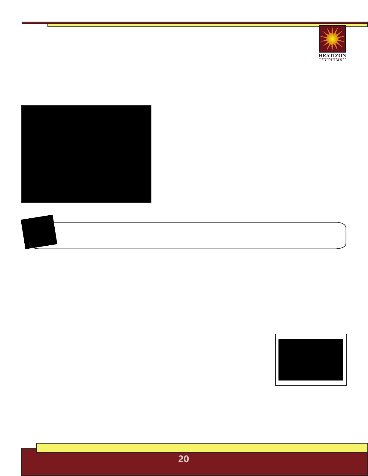
6.1 MEASURE THE RESISTANCE (TEST #3)
Use a digital Ohm meter to measure the resistance of the Heatwave® Mat/Cable and
compare it to the total Ohms in the tables in Section 4.1 for Mats or in Section 4.2 for
Cables. Record the measured resistance on the Registration Form. Documenting the
resistance at each stage of installation is required for warranty purposes. Also, measure
the resistance between each conductor and the shielding/ground wire. Both should read infinity.
Please refer to Section 7 (Commissioning) for instructions on how to measure the resistance.
6.2 INSTALL FLOOR COVERING
To install tile, apply a layer of thin-set mortar using
the ridged side of the trowel. Tile and grout the floor
using best industry practices and in accordance with
instructions provided by the tile manufacturer.
6.3 CONNECT POWER SUPPLY AND THERMOSTAT
The connection of the power supply and the thermostat
must be done by a qualified person in accordance with
the National Electrical Code (NEC) and the Canadian
Electrical Code (CEC). Connect the floor sensor to the
thermostat, take the final resistance reading and record it
on the Registration Form, see 6.5.
6.4 MEASURE THE RESISTANCE (TEST #4)
Use a digital Ohm meter to measure the resistance of the Heatwave® Mat/Cable and compare
it to the total Ohms in the tables in Section 4.1 for Mats or in Section 4.2 for Cables. Record
the measured resistance on the Registration Form. Documenting the resistance at each stage
of installation is required for warranty purposes. Also, measure the resistance between each
conductor and the shielding/ground wire. Both should read infinity. Please refer to Section 7
(Commissioning) for instructions on how to measure the resistance.
6.5 RECORD INFORMATION AND AFFIX LABELS
It is important for the home builder/owner to retain a copy and mail in the
warranty certificate immediately after installing the system (Heatwave® Mat
or Cable and Thermostat). Failure to do so could void the manufacturer’s
warranty. The warranty is subject to the guarantee conditions listed on
the warranty certificate. Keep a copy of the Registration Form for future
reference. Place the included label “Electric Shock or Fire Hazard” on the
inside of the electrical power distribution panel.
6.6 ENJOY THE COMFORT OF HEATWAVE
The Heatwave® Heating System is now ready to use. Increase the floor temperature gradually
and adjust it until it reaches a comfortable level depending on the type of room and personal
preferences.
Mark the appropriate circuit breaker reference label indicating which branch
circuit supplies the power to each electric heating cable.
NOTE:
HEATIZON.COM
21
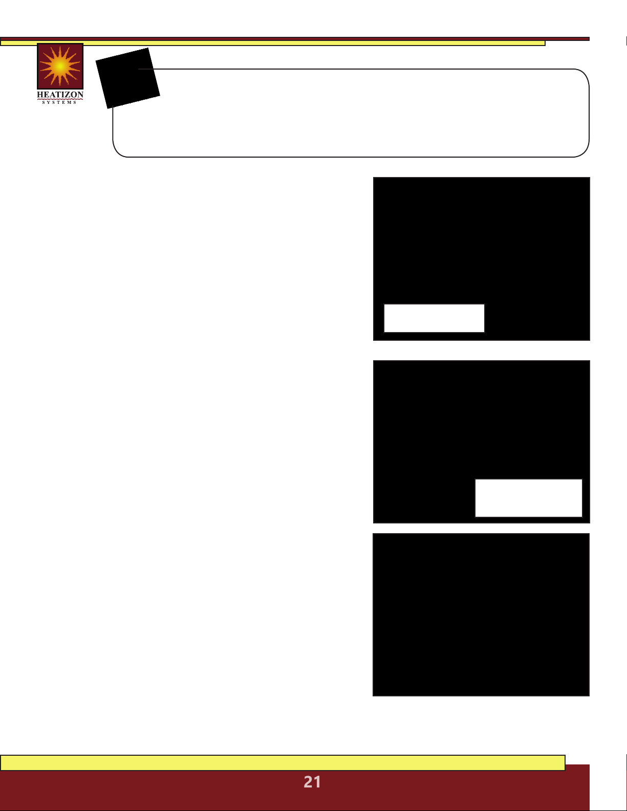
7. Commissioning
7.1 INSULATION RESISTANCE TEST
This test ensures that the insulating jackets of the heating
cable are not damaged. A low value indicates the cable
has been damaged and must be replaced.
A. Set the multimeter to 2000K ohm.
B. Connect* the ground wire to the black lead and both
white conductors to the red lead of the multimeter.
C. Make sure the meter indicates, “Open,” “OL” or
infinity. If there is a different reading, contact
Heatizon at 888-239-1232.
D. Record these readings on the Registration Form.
7.2 HEATING CABLE RESISTANCE TEST
This test measures the resistance of the Heatwave® Mat
or Cable, and is used to determine circuit integrity.
A. Set the multimeter to the 200 or 2000 ohm range.
B. Connect* the multimeter leads, one to each white
conductor on the cold lead.
C. Compare this resistance reading to the resistance
specified in the tables in Section 4.1 or 4.2. The value
should be within ±10%. If there is a different reading
than expected, contact Heatizon at 888-239-1232.
D. Record these readings on the Registration Form.
7.3 SENSOR RESISTANCE TEST
This test measures the resistance of the floor sensor and is
used to verify the sensor integrity.
A. Set the multimeter to the 200K ohm range.
B. Connect* the multimeter leads to
each sensor lead wire.
C. Make sure the meter reads between 9-25K ohms.
If there is a different reading, contact
Heatizon at 888-239-1232.
* Be sure when connecting the multimeter to the leads, do not touch the
connection with bare hands or that two connections do not touch.
Important: For the Limited Lifetime Warranty to apply, these tests
MUST be performed, record the results on the Registration Form, and
retain a copy of the record. These tests MUST be performed: Insulation
Resistance Test, the Heating Cable Resistance Test, and the Sensor Resistance Test
four times (please refer to Installation Instructions) during the installation process.
Refer to tables on page 12
(Mats) or page 14 (Cables)
for ohm values
BE SURE TO NOT TOUCH THE
WIRES WITH YOUR BARE HANDS
WHILE DOING THIS TEST
HEATIZON.COM
22
8. Thermostat Quick Start
After the M429 GFCI Thermostat has been installed and powered on, there are a few
settings to adjust in order to take full advantage of the Heatwave system. This is a
quick start guide, for complete instructions, please consult the manual included with
the thermostat. A downloadable installation manual for the complete system and the thermostat
instruction manual are available online at: heatizon.com/heatwave.
8.1 SET TIME AND DAY
8.1.1 SETTING THE TIME
Upon the first power-up the unit should automatically require setting the
current time. Using the UP and DOWN arrow buttons adjust the hour to
the current hour. Then press the OK button to move to the minutes, adjust
minutes using the UP or DOWN buttons. Then press the OK button.
8.1.2 SETTING THE CURRENT DAY
After setting the time, there will be a prompting to
choose the correct day of the week. Select the current
day using the UP or DOWN buttons, then press the OK
button. Then be returned to the main screen.
8.2 HOME SCREEN
This is the default screen for a powered on and partially setup unit.
8.3 SCHEDULE SELECT
On the main menu, the second option down SCHEDULE (press
OK to select the SCHEDULE settings, and OK again to edit these
settings) is for determining whether the unit will
run a program based on the following options:
• 7:0 - Runs the same temperature and time
settings every day of the week.
• 6:1 - Six days of the week the temperature
and time settings are the same, while Sunday
is on a separate program.
• 5:2 - The program will run the same
temperature and time Monday through Friday,
but will run a separate program on Saturday
and Sunday.
Using the UP or DOWN buttons select a desired schedule for the thermostat,
then press the OK to confirm the choice.
POWER BUTTON: Pressing this button once powers on the unit, holding
it down for a few seconds turns it off. While not in Active Mode (no screen
backlight), press the OK button twice to enter the menu.
NOTE:
HEATIZON.COM
23
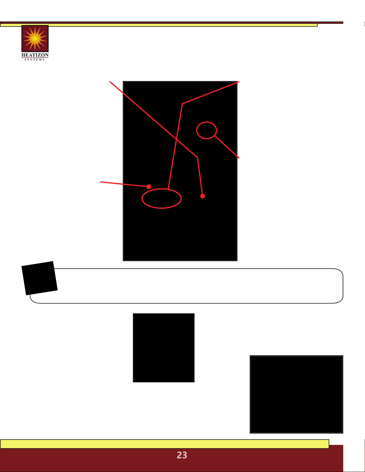
8.4.1 FIRST SELECTION:
Setting program based on
preferred SCHEDULE settings
(see section 8.4). This will
either be one or two different
programs. The first program
will be blinking. To change the
SCHEDULE to program, use the
UP or DOWN buttons. Press
the OK button to edit that
program.
8.4.2 SECOND SELECTION:
Setting time period to be
programmed. Using the UP or
DOWN buttons to select one
of the following, then pressing
OK to edit:
• MORNING
• DAY (AWAY)
• EVENING (HOME)
• NIGHT
8.4.3 THIRD SELECTION:
This is where the exact activation
time for the time period is set.
Use the UP and DOWN buttons
to adjust the time accordingly.
Press OK once done. (Time is
adjusted in 15 minute increments. Only
one exact time per period is available.)
8.4.4 FINAL SELECTION:
The last setting is where the
desired temperature is selected.
Using the UP and DOWN
buttons select a temperature.
Press OK to confirm the setting.
(The range is between 32° - 104°
Fahrenheit, however the Heatwave
system may not be able to heat to that
same range based on several factors.)
8.5 MODE SELECT
On the main screen, the MODE
menu will be shown blinking
first with three options:
• AUTO - Default mode that
most users will want to use
which sets temperature
based on a user-created
schedule.
• OVERRIDE - To temporarily override
temperature/schedule settings.
• MAN. MODE - To use the thermostat
to adjust the temperature on user input
without a schedule.
Each time OK is pressed, the program, will automatically move to the program section.
In the case where there are two schedules, once the final setting for the first schedule is
finalized, hitting the OK button will move to the next schedule to program, if applicable.
NOTE:
8.6 OTHER SETTINGS
SETTINGS (fourth menu item from the
top) is where several other options can
be configured for this thermostat. Please
consult the user manual included with the
thermostat
for complete
information
about these
options.
8.4 PROGRAM SELECT
The third option down PROGRAM (press OK to select the PROGRAM settings, and OK
again to edit these settings) is where the majority of thermostat programming takes
place. All the programming in this function will be done using the UP, DOWN and OK
buttons.
HEATIZON.COM
24
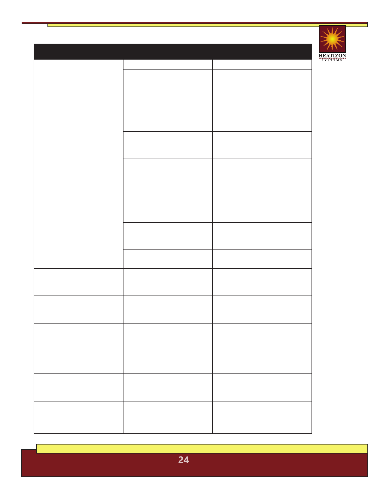
Symptom Probable Causes Corrective Action
Floor doesn’t heat No voltage. Check circuit breaker.
Circuit breaker tripped. Ensure that there are not too
many appliances connected
on the same circuit. The
Heatwave® Mat may require
a dedicated circuit. See the
Product Selection “Table 1” of
this manual
Ground-fault tripped in
the thermostat.
Refer to Thermostat
Installation and Operation
Manual.
Thermostat not turned on Refer to Section 4 of this
manu-al and the Thermostat
Installation and Operation
Manual
Cable not connected to
thermostat
Refer to Thermostat
Installation and Operation
Manual.
Floor temperature sensor
not connected
Refer to Thermostat
Installation and Operation
Manual.
Faulty sensor. Contact Heatizon Systems at
888-239-1232.
Floor warm all the time Clock not set correctly. Refer to Thermostat
Installation and Operation
Manual.
Floor not warm enough Thermostat setting not set
correctly
Refer to Thermostat
Installation and Operation
Manual.
Thermostat shows “E2” on
screen
External Sensor not
properly connected.
Check internal connections
from floor sensor to
thermostat.
(For more troubleshooting directly related to
the Thermostat, please see the thermostat
instructions included. Also available on our
website.)
Installation instructions Download Heatwave®
Installation instructions from
www.heatizon.com
Cut or damaged the cable Call Heatizon immediately:
888.239.1232 or
(8 am - 5 pm, (MST) M-F, Closed holidays)
9. Troubleshooting
HEATIZON.COM
25
10. FAQs
Q: What can I cut?
A: The red heating cable in the mat and free-roll cable CANNOT BE CUT
under any circumstances. The mat (the white mesh part) can be cut. The end of
the sensor cable (not the blub end) can be cut/shortened. The unconnected end of
the cold lead (thicker black cable) can be cut/shortened.
Q: Can either the mat or cable be used for an outside application?
A: No, but contact Heatizon to hear about one of our many other solutions
for outdoor applications.
Q: Can either the mat or cable be used for an outside application?
A: No, but contact Heatizon to hear about one of our many other solutions
for outdoor applications.
Q: The junction between the heating cable and the cold lead is thick, what methods
can be used to ensure that it will not cause the flooring above it to lift up.
A: When installing and embedding the junction into thinset and/or mortar if there is a
concern that the junction will cause issues with the flooring. There are two methods:
1. Raise the level of the thinset/mortar to account for the additional
thickness of the junction.
2. Depending on the type of subfloor, make a groove/cut for the
junction to sit down into, lowering the profile of the junction.
Q: Which system mat or cable is the better system?
A: Each system has it’s advantages, but briefly, the mat system is installed faster and is
better for areas that are square/rectangle. The cable system is better for odd
shaped areas and allows for more customization as far as watt density.
Q: Where should the thermostat be located?
A: Wherever the end-user prefers, but take into account that the sensor is 10’ long and
the cold lead is 15’ long. Walls without existing electrical is preferred.
Q: Can the thermostat be upgraded if a different model is preferred?
A: Yes, contact Heatizon (888-239-1232) for the available options.
Q: Can multiple mats/cables be controlled with one thermostat?
A: Yes as long as the amp load for the thermostat is not exceeded. (Consult either an
electrician or Heatizon and the thermostat specifications.)
Q: Can multiple mats/cables be controlled independently of each other with the
same thermostat?
A: No, the thermostat will control mats/cables connected to it as if they are one unit.
Q: What is the difference between the 240V and 120V systems?
A: The 240V systems use half the amperage of the 120V systems, allowing them to be
better suited for larger areas and combining multiple units.
HEATIZON.COM
26
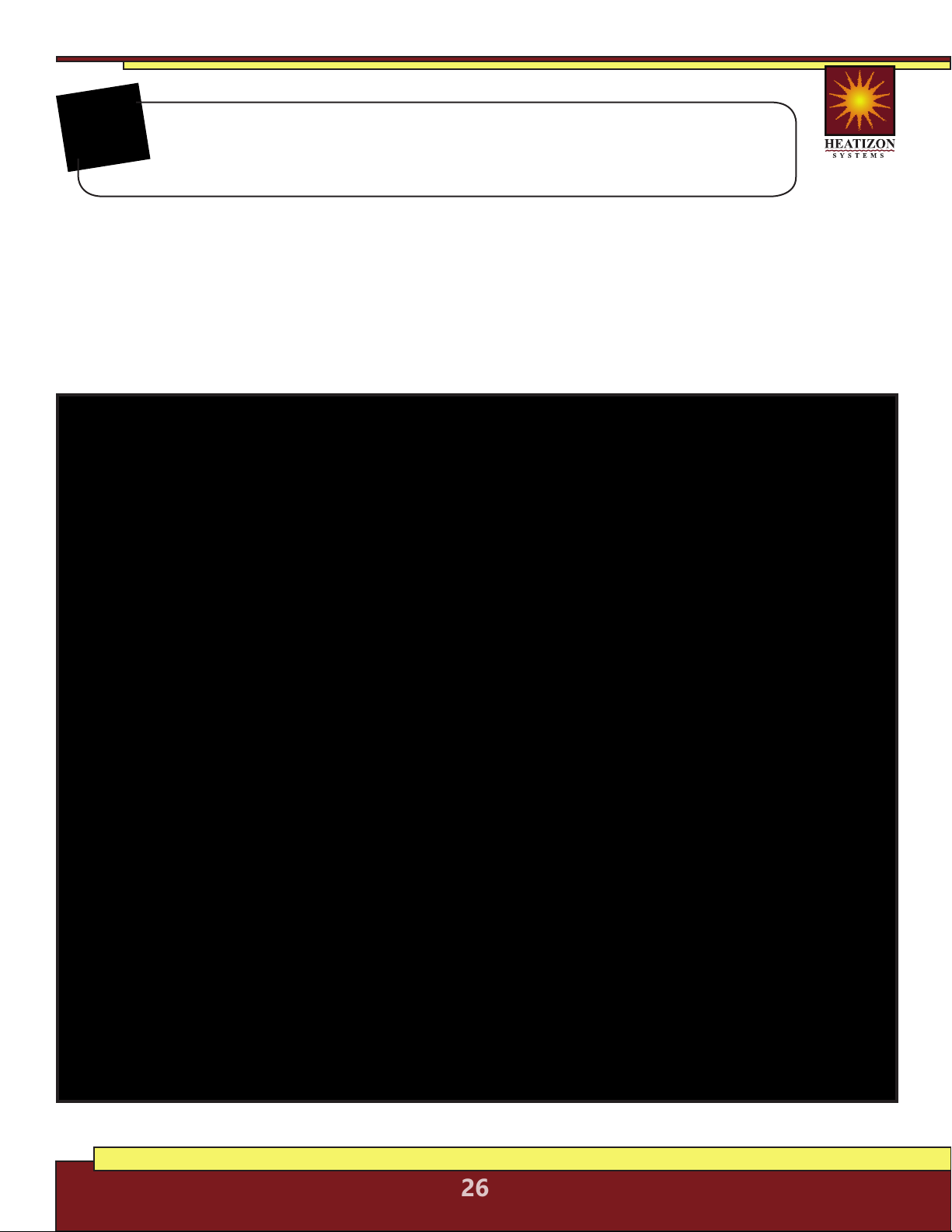
All Electrical Connections for the Heatwave® Floor Warming System
and Controls should be performed by a Professional Electrician in
accordance with all Local and National Electrical Codes.
NOTE:
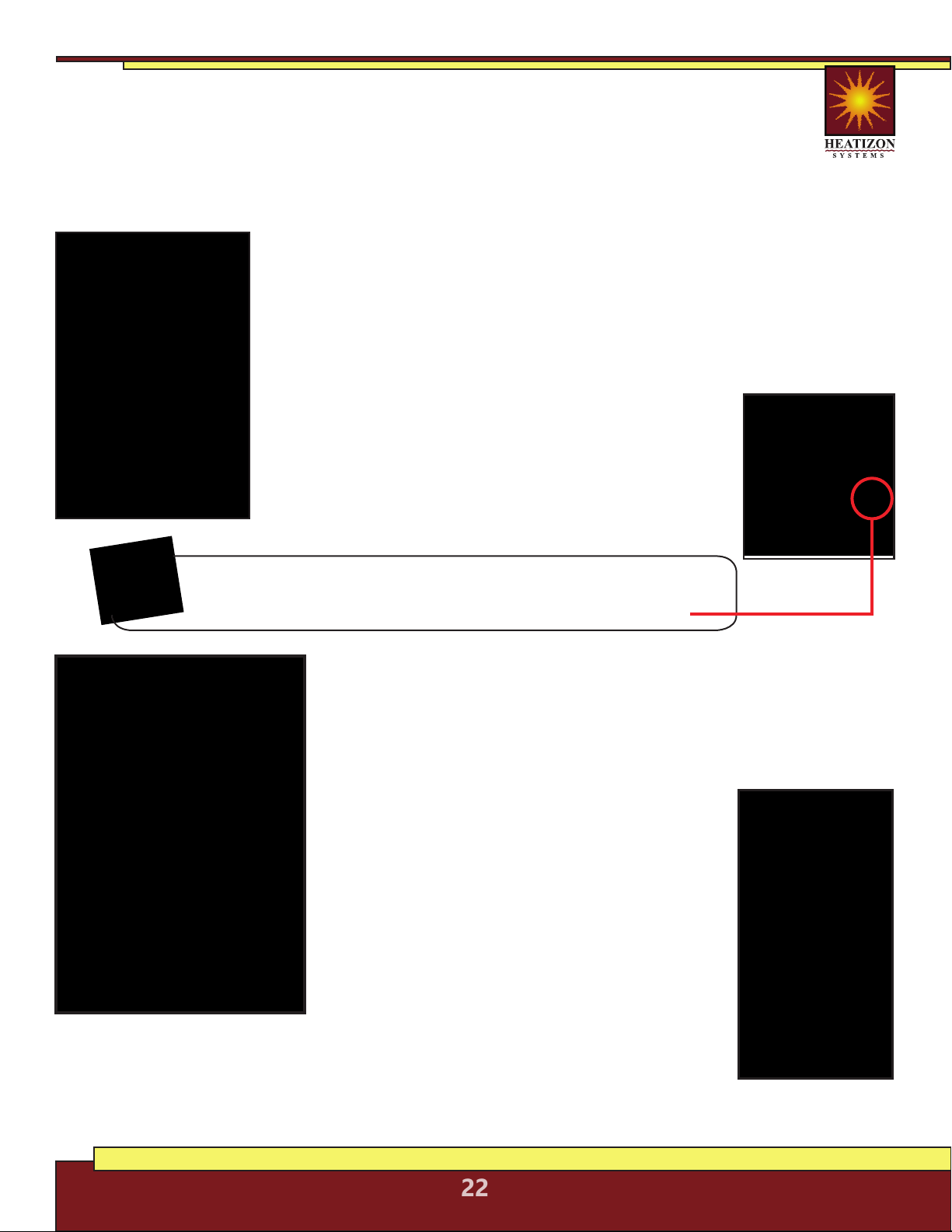
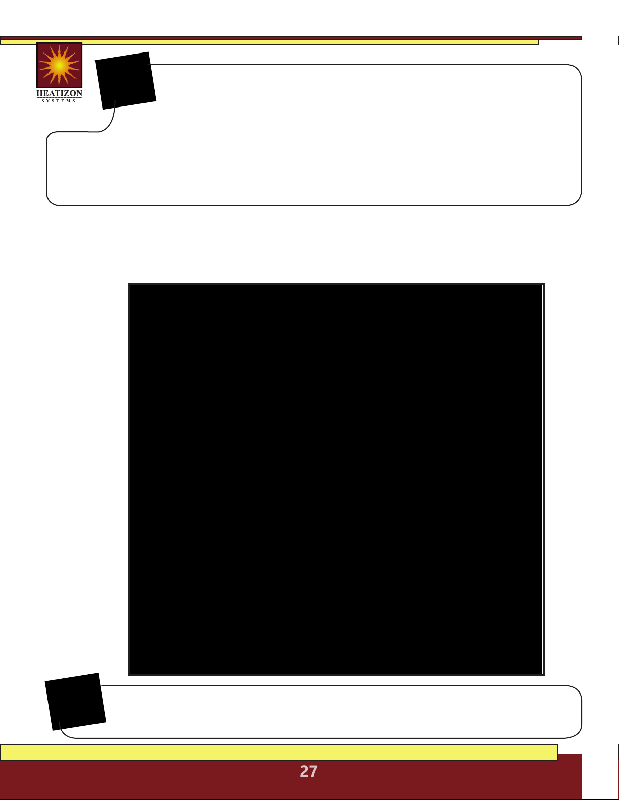
Electrical Connection Details
A deep, 2 1/8” X 4” single-gang junction box (or a “roomier” 4” X 4” double-gang box with a
mud plate) should be provided by the electrician for the thermostat connections. See Rough-In
Electrical Preparation Diagram below.
HEATIZON.COM
27
• Consult the quick start thermostat programming guide on pages
22-23 once the thermostat installation is completed.
• Instructions for programming, wiring and troubleshooting of the M429 thermostat are
included in the box and available on the Heatizon website.
• The sensor cable and cold lead coming into the box for the
thermostat can be shortened if needed.
• Ensure that the sensor cable is separate from all power cables and
enters into a different box port.
NOTE:
Thermostat Electrical Connection Details
The M429-PM is and optional device available from Heatizon for instances when multiple cables or
mats need to be controlled by one thermostat, but exceed the amp rating of the single thermostat.
For information about this advanced install method please contact Heatizon at 888-239-1232.
NOTE:
This diagram is a quick reference for the connections for power and mat/cable to the M429
thermostat and the M429-PM (optional). Consult the diagrams included with the thermostat for
further information.
Use this grid to layout the Heatwave®system.
Heatwave® Limited Warranty
Heatizon Systems warrants the Heatwave® product to be free of defects
in materials and workmanship for the life of the floor covering installed
with the Heatwave® cable and mat product while in possession of the
original owner, provided:
1. The product is installed and tested in accordance with the
Installation/ Homeowners Manual and Heatwave® Resistance
Documentation Procedures.
2. The installation is registered with Heatizon Systems within 10 days of the installation date. This
registration is accomplished by the installer and/or homeowner, who must complete and return
the Installation Registration Form to Heatizon Systems (at the address given below).
3. The product was not damaged or misused by the homeowner or any tradesman/agent of the
owner. Heatizon Systems takes no responsibility under this warranty for damage caused by the
homeowner or tradesman retained by the homeowner.
4. Heatwave® cable and mat products must be controlled by a thermostat with a floor sensor.
5. The density supply must not exceed 15 Watts per square foot.
Heatizon Systems staff will be available to provide advice and consultation to the installers of the
Heatwave® product to assure that they are informed concerning the procedures required to complete
a proper installation. Controls used to operate the Heatwave® product are warranted by their
manufacturers according to their warranty policies. Under this Limited Warranty, Heatizon Systems
will, at its option, provide either or both of the following:
A. Technical support (by phone) to assist the installer(s) in isolating the problem area. If deemed
repairable, the appropriate repair kit shall be provided. In such a case, ALL OTHER MATERIALS AND
LABOR necessary to complete the repair of the affected area must be supplied by the homeowner
B. Credit for the faulty Heatwave® product up to the limit of the original price of the Heatwave®
product used in the installation, as Heatizon Systems’ sole obligation under this LIMITED warranty.
This LIMITED Warranty is null and void if the owner does not inform Heatizon Systems of the problem
within thirty (30) days of it’s discovery OR if the homeowner or any tradesman retained by the
homeowner attempts to repair the problem without informing and consulting with a staff member of
Heatizon Systems regarding the appropriate testing and/or repair procedures.
HEATIZON SYSTEMS DISCLAIMS ANY WARRANTY NOT PROVIDED HEREIN INCLUDING THE IMPLIED WARRANTY OF
MERCHANTIBILITY AND IMPLIED WARRANTY OF FITNESS FOR A PARTICULAR PURPOSE. HEATIZON SYSTEMS FURTHER
DISCLAIMS ANY RESPONSIBILITY FOR LOSSES, EXPENSES, INCONVENIENCES, SPECIAL, INDIRECT, SECONDARY,
INCIDENTAL, OR CONSEQUENTIAL DAMAGES ARISING FROM OWNERSHIP OR USE OF THE PRODUCT. THERE ARE NO
WARRANTIES THAT EXTEND BEYOND THE FACE HEREOF.
Heatizon Systems
4137 South 500 West
Murray, UT 84123
Phone (801) 293-1232 Fax (801) 293-3077
heatizon.com
From Heatizon Systems
4137 South 500 West
Murray, Utah 84123
888-239-1232 | heatizon.com

Heatwave® Installation Registration Form
Instructions: This form must be completed and returned for each installation. A copy
should be retained by the homeowner. An installation is defined as each individual space
or room in which Heatwave® is installed such as a bathroom, kitchen, sunroom, etc.
Each Heatwave® shipment includes the following information essential to the proper
installation of the products: Installation/Homeowners Manual, Wiring Diagrams, and
Theoretical Ohm Readings necessary to test the products. If any of this information is
missing from the shipment, please call the dealer or our service department at
1-888-239-1232.
TO ENSURE WARRANTY PROTECTION FOR THE INSTALLATION(S), THE HOMEOWNER OR INSTALLER MUST
COMPLETE ALL THE INFORMATION BELOW FOR EACH INSTALLATION AND RETURN THIS FORM TO HEATIZON
SYSTEMS AT THE ADDRESS LISTED BELOW WITHIN 10 DAYS OF THE COMPLETED INSTALLATION.
I. Installer Information:
Installer’s Name: _________________________________________________________ Installation Date: ___-___-___
Business Address ______________________________________________________________________________________
Phone Number: _____-_____-______ Email Address: _____________________________________________________
Name of Company (from which Heatwave® was purchased) _________________________________________
II. Owner Information:
Owner’s Name: ________________________________________________________________________________________
Home Address: ________________________________________________________________________________________
Phone Number: _____-_____-______ Email Address: _____________________________________________________
Name of Space and Location in Structure where installed: ____________________________________________
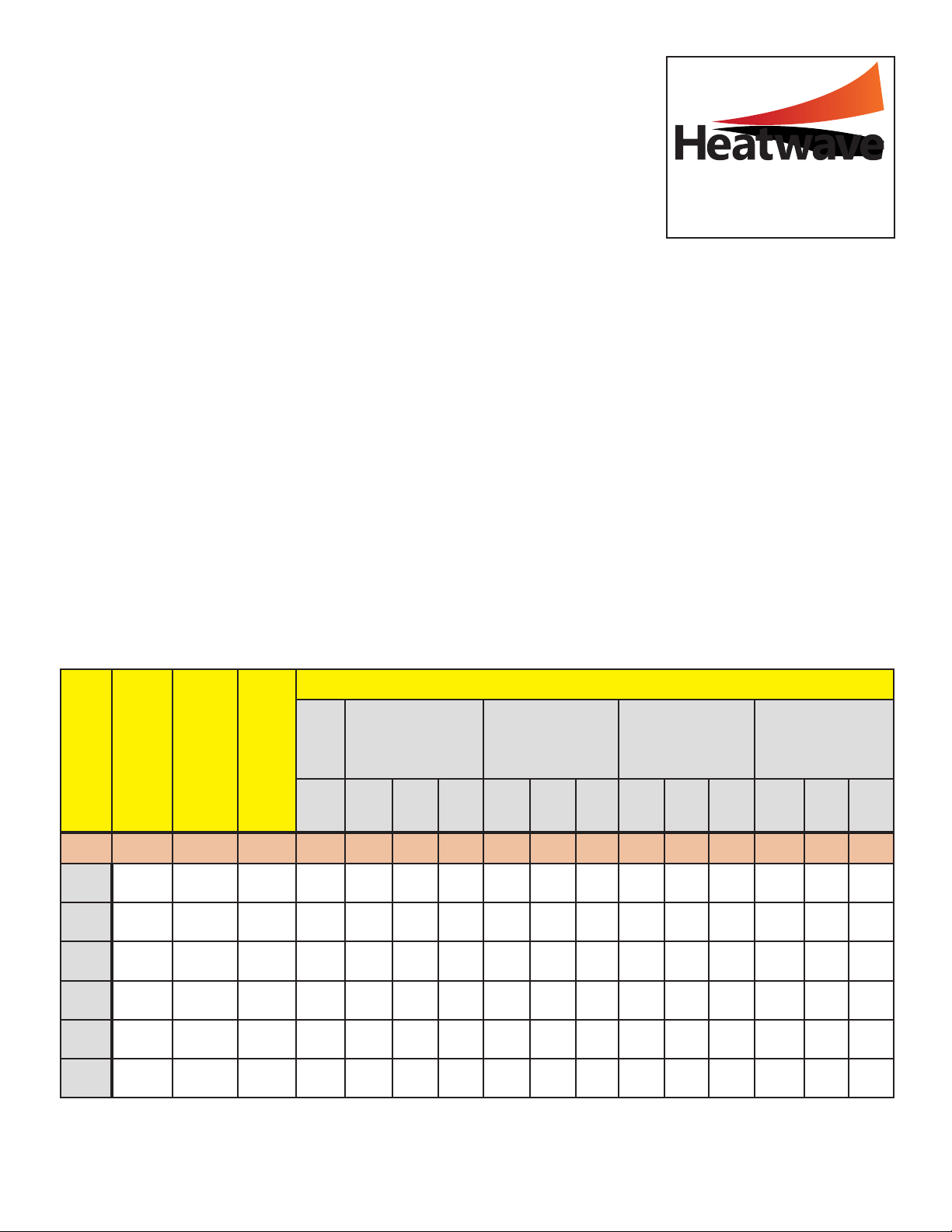
III. Products Used in Installation:
(List Each Heatwave® Mat or Cable on a Separate Line)
(Note: “Hot” or “Neutral” in this table indicates the white conductors in the Cold Lead)
Confirmation: The above information was measured and recorded correctly as indicated on the measuring
instrument, and the enclosed drawing shows the final layout of the products and the electrical connections.
Installer’s Signature: ________________________________________________________________________________________________________
Mat or
Cable
Number
Model # Total Watts Volts
R E S I S T A N C E I N O H M S
Received
After Mat is customized/cut
(Optional test—Mats only)
After Mat/Cable is attached
to subfloor/underlayment
After Mat/Cable is embedded
in thinset or mortar
After flooring has been In-
stalled on top of Mat/Cable
Hot
to
Hot/
Neutral
Hot
to
Hot/
Neutral
Hot
to
Ground
Neutral
to
Ground
Hot
to
Hot/
Neutral
Hot
to
Ground
Neutral
to
Ground
Hot
to
Hot/
Neutral
Hot
to
Ground
Neutral
to
Ground
Hot
to
Hot/
Neutral
Hot
to
Ground
Neutral
to
Ground
SAMPLE 1x 50 750 120 19.2 19.2 Open Open 19.2 Open Open 19.2 Open Open 19.2 Open Open
#1
#2
#3
#4
#5
#6
From Heatizon Systems
4137 South 500 West
Murray, Utah 84123
888-239-1232 | heatizon.com