
NVR and Camera
Configuration Guide

NVR and Camera Configuration Guide
AcuSense NVR and Camera Configuration Guide 071219NA 2
INTRODUCTION .......................................................................................................................................................... 3
Demand Analysis ................................................................................................................................................ 3
Solution ............................................................................................................................................................... 3
System Architecture .......................................................................................................................................... 3
Function Description ............................................................................................................................................. 4
Target Classification .......................................................................................................................................... 4
False Alarm Reductions and Quick Target Search ......................................................................................... 4
Configuring False Alarm Reductions.................................................................................................................... 5
Configuring Arming Schedule ............................................................................................................................... 7
Configuring Linkage Method ................................................................................................................................. 8
Configuring White Light Output (Strobe Light and Audio Alarm/SL Model Only) ........................................... 9
Configuring Audible Alarm Output (Strobe Light and Audio Alarm/SL Model Only) ....................................... 9
Checking Alarms ................................................................................................................................................... 11
Quick Target Searching ....................................................................................................................................... 12
File Management Search ................................................................................................................................. 12
Smart Search .................................................................................................................................................... 14
False Alarms Search ........................................................................................................................................ 15
iVMS-4200 Client .................................................................................................................................................. 16
Adding a Network Camera ............................................................................................................................... 16
Viewing Alarm on GUI Interface ........................................................................................................................... 17
Viewing Alarms on iVMS-4200 ............................................................................................................................. 18
Known Issue ...................................................................................................................................................... 19
Product List ........................................................................................................................................................... 19
Installation Requirements................................................................................................................................... 19

NVR and Camera Configuration Guide
AcuSense NVR and Camera Configuration Guide 071219NA 3
INTRODUCTION
Demand Analysis
In traditional CCTV systems, all the moving objects in the picture will trigger the perimeter alarm, which
may generate a lot of false alarms. Users have to waste a lot of time dealing with false alarms, and the
alarm is unreliable. In addition, when the target needs to be found in the video, it needs to be manually
searched by video playback, which is time consuming and laborious, and it is easy to lose key targets,
which is very inconvenient.
After solving the basic monitoring and video problems, users need to receive more accurate alarms
and to have a more convenient target search function to better use the monitoring system.
Solution
Some false alarms can be filtered by using a thermal camera, vibration optical fiber, radar, and other
equipment. The cost of the whole system is too high, and it cannot meet the requirement of finding
the target quickly afterwards.
With the development of artificial intelligence, target classification can be realized directly based on
the video screen, and false alarm reductions and target retrieval can be provided, which can provide
users with very cost-effective schemes.
System Architecture
Hikvision’s AcuSense Series of cameras and NVRs can prevent false alarms by identifying humans and
vehicles when defining line crossing detection and triggering an alarm when only the selected object
type (human and/or vehicle) is detected.
To set up False Alarm reductions and target classification without additional products, an AcuSense
NVR and/or AcuSense cameras are required.
Figure 1, System Architecture Diagram

NVR and Camera Configuration Guide
AcuSense NVR and Camera Configuration Guide 071219NA 4
Function Description
Target Classification
By upgrading the hardware of conventional products, Hikvision has loaded artificial intelligence
technology into the chip of the equipment. The equipment can classify and identify the objects
appearing in the picture such as humans, vehicles, rainwater, light, leaves, animals, etc. Object
classification is the basis for realizing false alarm and key target alarms.
Figure 2, Target Classification
False Alarm Reductions and Quick Target Search
Through target classification, alarms caused by animals, light, rain, leaves, or other objects can be
filtered out, and only alarms triggered by human bodies and vehicles will be received. This is the
function of a false alarm reduction.
In addition, in the face of a large number of monitoring video data, when searching key information
such as people or cars, the target retrieval function is used. The device will record human body and
vehicle information automatically, and solve the issue that video playback is time-consuming and
easy to miss.
Figure 3, False Alarms

NVR and Camera Configuration Guide
AcuSense NVR and Camera Configuration Guide 071219NA 5
Figure 4, False Alarm Reductions and Quick Target Search
Configuring False Alarm Reductions
Figure 5, Configuration > Event > Smart Event > Area Settings

NVR and Camera Configuration Guide
AcuSense NVR and Camera Configuration Guide 071219NA 6
1. Go to Configuration > Event > Smart Event > Line Crossing Detection in the local interface.
2. Use the pull-down list to select the camera to configure.
3. Check the Enable Local Smart Analysis checkbox to have the local NVR perform the smart analysis
with a non-AcuSense camera. The NVR will acquire only the camera stream for intelligent event
analysis, and the NVR will not acquire the camera’s smart event configuration. Up to four 8 MP non-
AcuSense cameras are supported for false alarm reductions, and sub-stream resolution of these
cameras have to be under WD1 (960*576). If this box is unchecked, the AcuSense camera (required
in this case) will do the analysis. The NVR will acquire smart event configuration and alarm
information from the camera.
NOTE: The NVR and camera configuration screens will slightly differ. This document uses the NVR
configuration screens as examples.
4. Check the Enable Line Crossing Detection checkbox to activate line crossing detection.
5. Check one or both Detection Target checkboxes to set the type of object to trigger the alarm:
• Human: Alarm will be sent only if triggered by human(s).
• Vehicle: Alarm will be sent only if triggered by vehicle(s).
• No Box Checked: Alarm will be sent by any object(s).
6. Click the Area Settings tab.
7. Use the pull-down menu to set the line number to define (1−4). Up to four line crossing lines can be
defined. The target classification can be set separately for each line.
8. Drag a line in the live view area with the left mouse button; release to end the line. Select line with
left mouse button to move or resize the line.
9. Configure the line by clicking on one of the buttons:
• Max. Size
∗
∗∗
∗
: Drag with the left mouse button to define a rectangle representing the maximum
object size that will be detected crossing the defined line.
• Min. Size
*
: Drag with the left mouse button to define a rectangle representing the minimum
object size that will be detected crossing the defined line.
• Draw Area: Drag with the left mouse button to define the total area to monitor.
• Clear: Click Clear, then click Save, to delete all line settings.
10. Use the pull-down menu to select the line crossing direction that will trigger the alarm:
• A<->B: Alarm will be triggered if object moves across the defined line from A side to B side or
from B side to A side.
• A->B: Alarm will be triggered if object moves across the defined line from A side to B side.
*
Available only when configuring through the local NVR; setting will not appear if configuring through the camera.

NVR and Camera Configuration Guide
AcuSense NVR and Camera Configuration Guide 071219NA 7
• B->A: Alarm will be triggered if object moves across the defined line from B side to A side.
11. Set line crossing Sensitivity (0−100). The sensitivity value = 100 - S1/ST x 100, where S1 is the area
of the target that has crossed the line and ST is the actual area of the target. The higher the
sensitivity, the easier it is to trigger the alarm.
12. Click Save to save the line crossing settings.
13. Repeat for additional lines, up to four total.
14. Click Save.
Configuring Arming Schedule
Figure 6, Arming Schedule
1. Click the Arming Schedule tab to display the Arming Schedule section.
2. Drag the left mouse button to draw/modify blue timelines to define the times and days that the
defined alarm will be active. The line may be resized and/or re-positioned using the mouse.
NOTE: Click X Delete to delete a highlighted blue timeline.
Click the Delete All to delete all of the defined blue timelines.
3. Click Save to save the schedule settings.
NVR and Camera Configuration Guide
AcuSense NVR and Camera Configuration Guide 071219NA 8
Configuring Linkage Method
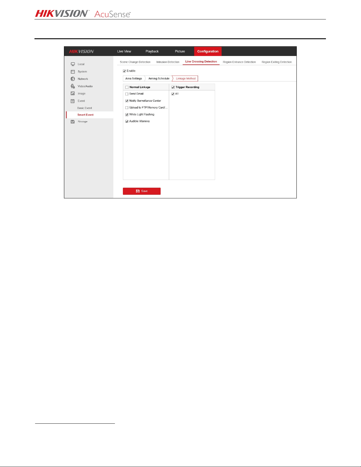
Figure 7, Linkage Method
1. Click the Linkage Method tab to display the Linkage section.
2. Check the alarm action checkboxes you wish to configure:
•
Normal Linkage
˗ Send Email − An alarm will cause the system to send an e-mail notification to the pre-
defined e-mail address.
˗ Notify Surveillance Center − An alarm will cause notification to be sent to the pre-defined
Surveillance Center.
˗ Upload to FTP/Memory Card − An alarm will cause the system to upload a notification to a
pre-defined FTP site or memory card.
˗ White Light Flashing (Strobe Light and Audio Alarm/SL models only) − An alarm will cause
the camera’s white light to flash (strobe).
˗ Audible Warning (Strobe Light and Audio Alarm/SL models only) − An alarm will cause the
system to generate an audible alarm.
•
Trigger Recording
*
˗ A1 − An alarm will cause this camera to start recording.
3. Click Save to save the alarm action settings.
*
Available alarm outputs will vary by NVR and camera.
NVR and Camera Configuration Guide
AcuSense NVR and Camera Configuration Guide 071219NA 9
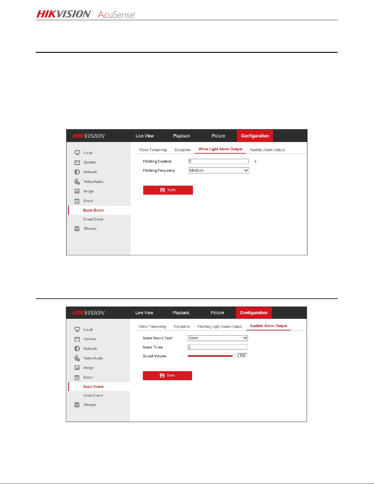
Configuring White Light Output
(Strobe Light and Audio Alarm/SL Model Only)
1. Go to Configuration > Event > Basic Event > White Light Alarm Output.
2. Set Flashing Duration from 1 to 60 seconds.
3. Set Flashing Frequency to High (interval 0.6 seconds), Medium (interval 1 second), or Low (interval
1.5 seconds).
4. Click Save to save the settings.
Figure 8, White Light Alarm Output
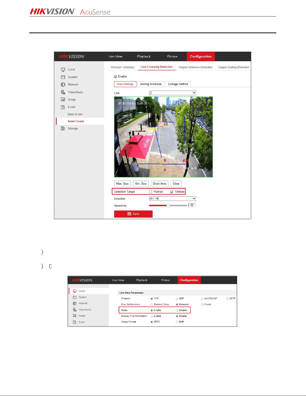
Configuring Audible Alarm Output
(Strobe Light and Audio Alarm/SL Model Only)
Figure 9, Audible Alarm Output
1. Go to Configuration > Event > Basic Event > Audible Alarm Output.

NVR and Camera Configuration Guide
AcuSense NVR and Camera Configuration Guide 071219NA 10
2. Set Alarm Sound Type − Click the drop-down list to select one of 10 types of built-in alarm sounds.
NOTE: Importing local audio files is not supported.
Details of 10 Types Built-in Alarm Sounds
Number
Details of Alarm Sounds
1
Siren
2
Warning, this is a restricted area
3
Warning, this is a restricted area, please keep away
4
Warning, this is no
-
parking zone
5
Warning, this is no
-
parking zone, please keep away
6
Attention please, the area is under surveillance
7 Welcome, please notice that the area is under surveillance
8
Welcome
9
Danger! Please keep away
10
(Siren)
a
nd
Danger! Please keep away
Figure 10, Alarm Sound Type Pull-Down List
3. Set Alarm Times −
−−
− Enter how many times the alarm sound will repeat, from 1 to 50 times
4. Set Sound Volume −
−−
− Volume can be set from 1 (softest) to 100 (loudest).
NVR and Camera Configuration Guide
AcuSense NVR and Camera Configuration Guide 071219NA 11
Checking Alarms
Use the Web interface to check the defined alarms.
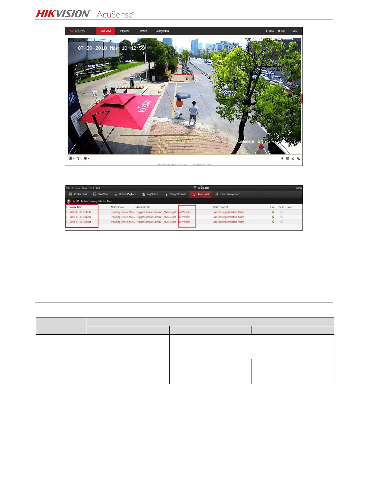
Figure 11, Line Crossing Detection (Target: Vehicle)
1. Perform the following steps to show the defined lines and draw area overlaid on the image.
1
)
Go to Configuration > Local > Rules.
2
)
Check the Enable checkbox.
Figure 12, Enable Target Rule Box
2. Check the alarm on the network camera’s Web preview interface. When someone crosses the line,
the perimeter box and line crossing lines turn red.
NVR and Camera Configuration Guide
AcuSense NVR and Camera Configuration Guide 071219NA 12
Figure 13, Human Triggers Line Crossing Detection Alarm
Figure 14, iVMS-4200 Filter Human Alarm
NOTE: The rule box displayed in the network camera Web preview interface does not make target
classification judgments; the alarm information is subject to the search result received from
the alarm receiver and NVR. A comparison of the Web interface with the alarm receiver (such as
iVMS-4200 client) can be used to distinguish if false alarm reductions has been performed.
Quick Target Searching
NVR Search Capabilities
NVR Model
Quick Target Search
File Search
Smart Search
False Alarm Search
I
-
Series NVR
(Requires FW
4.21.005 or later)
Displays all human and/or
vehicle pictures or videos,
as specified
Not Supported
AcuSense NVR
Displays all
human/vehicle
pictures and videos
Supported
File Management Search
1. On an AcuSense I-Series NVR, go to File Management.
2. Highlight Human Files or Vehicle Files.
3. Time: Set the time frame you wish to search.
4. Camera: Set the camera you wish to search.

NVR and Camera Configuration Guide
AcuSense NVR and Camera Configuration Guide 071219NA 13
5. File Type: Set file type you wish to search, Videos or Pictures.
For DS-9664NI-I8 local interface, file type must be specified with
search conditions.
NOTE: AcuSense NVRs can switch between picture and video on the search results page without
having to perform the search again.
6. Set the search choices:
• Select the target image in the red box area on the upper left corner, and listed picture will be a
close-up view of the target.
• Select the source image in the red box area on the upper left corner, and listed picture will be
the original picture.
• Select video in the red box on the upper right corner, and listed files will all be video files.
• Select picture in the red box on the upper right corner, and listed files will all be picture files.
• Select All, and the images and videos will be displayed together.

NVR and Camera Configuration Guide
AcuSense NVR and Camera Configuration Guide 071219NA 14
iDS-7732NXI-I4/16P/4S Local Interface
File type can be actively switched using the options located at the top right. Both picture
and video results can also be listed together by using the
All
option.
Smart Search
AcuSense NVRs support smart search for Human Body Detection and Vehicle Search. Picture and video
is combined on the search results preview screen.
iDS-7732NXI-I4/16P/4S Local Interface

NVR and Camera Configuration Guide
AcuSense NVR and Camera Configuration Guide 071219NA 15
NOTE: I-Series NVRs do not support smart search for human and/or vehicle target filtering.
DS-9664NI-I8 Local Interface
False Alarms Search
AcuSense NVRs can display all false alarms by using the All Files search (set event type to “False
Alarm”). False alarms are generated by objects that approach being mistaken for a human or vehicle.

NVR and Camera Configuration Guide
AcuSense NVR and Camera Configuration Guide 071219NA 16
Figure 15, False Alarms
iVMS-4200 Client
Figure 16, Add Network Camera
Adding a Network Camera
1. Add the camera in the iVMS-4200 Device Management section.
Figure 17, iVMS-4200 View Alarm Information (Human)
2. View the triggered alarm on the iVMS-4200 Alarm Event interface. Alarm detail information will be
labeled Human or Vehicle, as shown in the figure below.
NVR and Camera Configuration Guide
AcuSense NVR and Camera Configuration Guide 071219NA 17
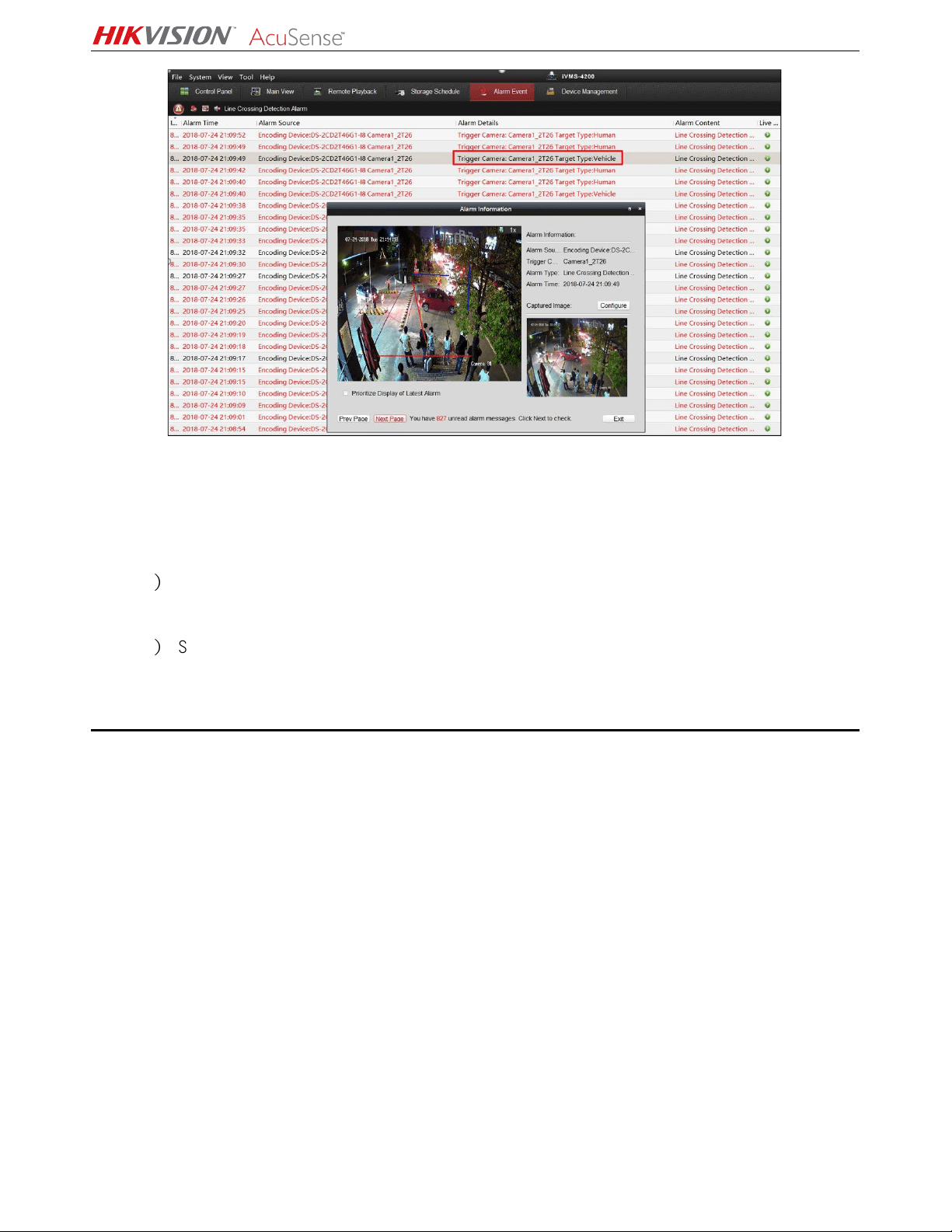
Figure 18, iVMS-4200 View Alarm Information (Vehicle)
NOTE: The Target Type shown on the iVMS-4200 is the same as the Detection Type set in the
configuration interface. Alarm information triggered by the unchecked category will be filtered
and will not be displayed on the iVMS-4200.
1
)
Set Detection Type to Human, then the iVMS-4200 will display only Human target type alarm
information.
2
)
Set Detection Type to Vehicle, then the iVMS-4200 will display only Vehicle target type alarm
information.
Viewing Alarm on GUI Interface
The NVR’s local GUI interface cannot classify Humans and Vehicles in this version.
The current mechanism: after checking Smart Detection, the GUI interface will display all alarm
pictures without classification between humans and vehicles (this feature will be optimized by the end
of the year).

NVR and Camera Configuration Guide
AcuSense NVR and Camera Configuration Guide 071219NA 18
Figure 19, NVR local GUI interface
Viewing Alarms on iVMS-4200
1. Add the NVR on the iVMS-4200 Device Management interface.
Figure 20, Add NVR on iVMS-4200
Figure 21, View Alarm Information on iVMS-4200 (Human)
2. View the triggered alarm on the iVMS-4200 Alarm Event interface. Alarm detail information will label
the target category as Human or Vehicle, as shown in the figure below.

NVR and Camera Configuration Guide
AcuSense NVR and Camera Configuration Guide 071219NA 19
Figure 22, View Alarm Information on iVMS-4200 (Vehicle)
The NVR alarm upload via iVMS-4200 is the same as for a network camera. The Target Type shown on
the iVMS-4200 is consistent with the Detection Type set on the configuration interface. Unchecked
categories will be filtered out and will not be displayed on the iVMS-4200.
Known Issue
When adding network cameras to the NVR, the NVR will issue a 24-hour arming schedule to the camera
by default. After the camera is connected, configuring an arming schedule on the NVR will affect only
whether the alarm is reported and displayed on this NVR, but the camera setting time will not change. If
other terminals access the camera, the alarm will still be received.
Product List
Scheme Camera NVR Client
AcuSense NVRs and
AcuSense Cameras
DS-2CD2/3xx6 AcuSense NVR V2.6.7.3 build 20180225
Installation Requirements
• The proposal altitude of installation distance is 3 to 5 meters, equipment bow angle is
approximately 10°, specific adjustments are according to the environment.
• The maximum monitoring distance depends on the lens’ focal length. The table of the maximum
monitoring distance for the specific focal length is as follows:
Lens (mm)
Recommended Maximum Monitoring Distance
2.8 mm
10 m
4 mm
15 m
6 mm
22 m
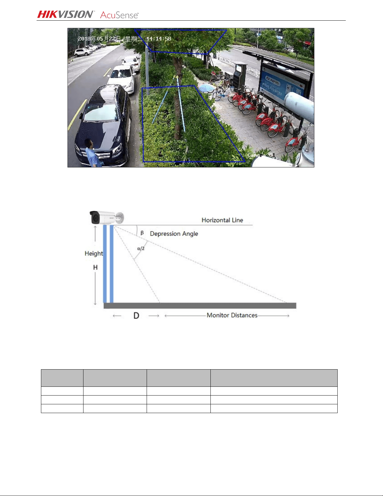
• The monitoring area cannot be covered by nearby objects. Do not shoot backlight at the
installation position, which will affect the image effect. The following shows a perimeter
environment installation:
NVR and Camera Configuration Guide
AcuSense NVR and Camera Configuration Guide 071219NA 20
Figure 23, Installation of the Perimeter Environment
• The equipment installation needs to pay attention to certain blind areas. The calculation method of
blind area distance is as follows:
♦ D = H · tan(90° − α/2
− β)
♦ D: Camera monitoring blind area H: Mounting height
♦ α: Vertical field Angle β: Angle of depression
Lens (mm)
Horizontal
Field Angle (γ)
Vertical
Field Angle (α)
Blind Area D
(Height 3.3 m, Depression Angle 10°)
2.8 mm
109°
62°
3.7 m
4 mm 90° 48° 4.5 m
6 mm
53°
39°
5.6 m
• Recommended Scenario:
- Try to avoid getting too close. It is recommended that the target be more than three meters
away from the camera. For example, avoid scenes with lots of trees nearby.
- If there is a mirror in the environment, the mirror image or shadow can easily lead to false alarm

NVR and Camera Configuration Guide
AcuSense NVR and Camera Configuration Guide 071219NA 21
triggering.
- Adjust the camera angle during installation to avoid interference from high brightness lights or
headlights.
- Domes are not recommended for outdoor scenes, IR reflect can seriously affect the accuracy of
the alarm, as shown below:
- Heavy traffic scenes such as station, airport, theater, etc., will generate a lot of perimeter
alarms, so it is suggested to avoid these types of scenes.
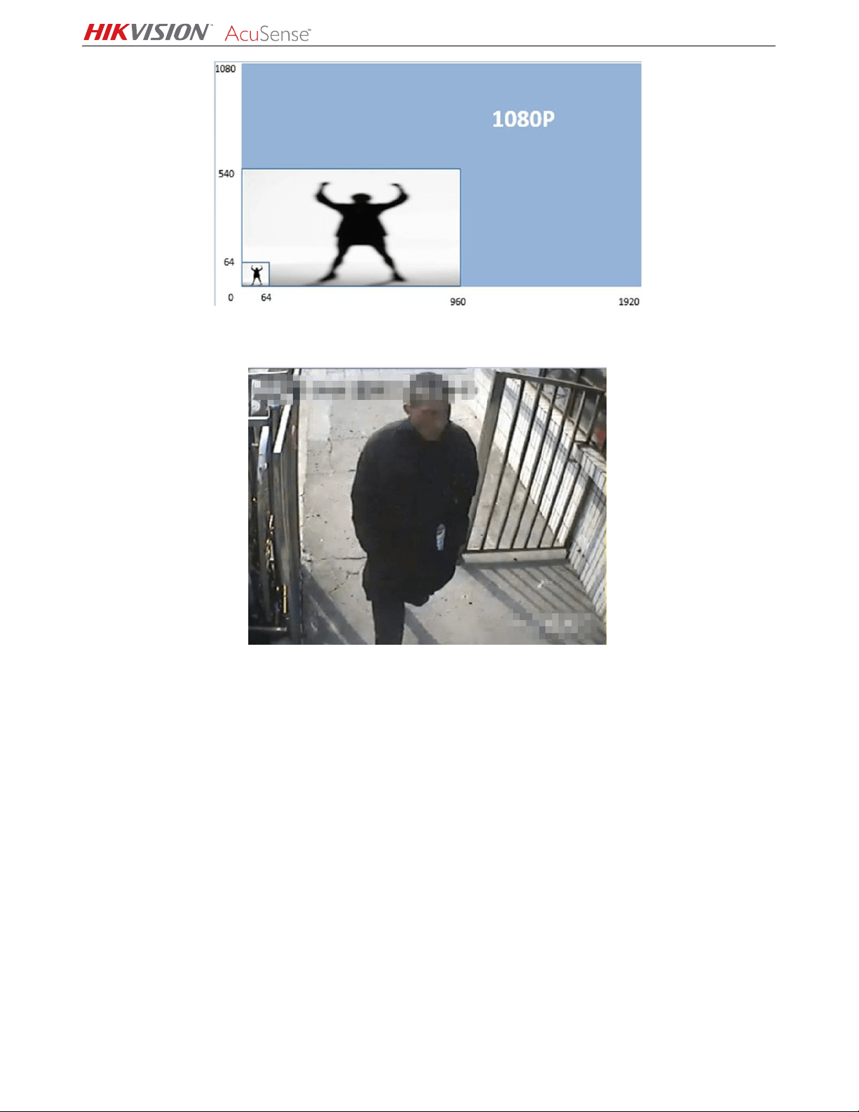
- Avoid situations where personnel targets are too large. AcuSense NVRs can analyze target sizes
between 1/16 and 1/2 of the image’s vertical size. For example, if the camera’s resolution is
1080p, the vertical size of the target should be between 64 and 540 pixels.
NVR and Camera Configuration Guide
AcuSense NVR and Camera Configuration Guide 071219NA 22
In the following scene, the target takes up almost the whole picture. Adjusting the camera angle so
that a targets is detected from a far distance so that it appears a suitable size is suggested.
Using Region Entrance/Exiting Detection instead of Intrusion/Line Crossing Detection is recommended
for region intrusion of fixed scenarios.