
Projector
ME382U/ME342U/ME372W/MC382W/
MC332W/ME402X/MC422X/MC372X/
MC342X/MC302X
User’s Manual
Please visit our web site for User’s Manual in the latest version:
https://www.nec-display.com/dl/en/pj_manual/lineup.html
•TheME342U,MC332W,MC422X,MC342XandMC302XarenotdistributedinNorthAmerica.
ModelNo.
NP-ME382U/NP-ME342U/NP-ME372W/NP-MC382W/NP-MC332W/NP-ME402X/NP-MC422X/NP-MC372X/
NP-MC342X/NP-MC302X

Ver.110/18
•Apple,Mac,MacOS,OSX,MacBook,andiMacaretrademarksofAppleInc.registeredintheU.S.andother
countries.
•iOSisatrademarkorregisteredtrademarkofCiscointheU.S.andothercountriesandisusedunderlicense.
•APPStoreisaservicemarkofAppleInc.
•Microsoft,Windows,WindowsVista,InternetExplorer,.NETFrameworkandPowerPointareeitheraregistered
trademarkortrademarkofMicrosoftCorporationintheUnitedStatesand/orothercountries.
•MicroSaverisaregisteredtrademarkofKensingtonComputerProductsGroup,adivisionofACCOBrandsinthe
U.S.andothercountries.
•AccuBlend,NaViSet,MultiPresenter,andVirtualRemotearetrademarksorregisteredtrademarksofNECDisplay
Solutions,Ltd.inJapan,intheUnitedStatesandothercountries.
•ThetermsHDMIandHDMIHigh-DenitionMultimediaInterface,andtheHDMILogoaretrademarksorregistered
trademarksofHDMILicensingAdministrator,Inc.intheUnitedStatesandothercountries.
•TrademarkPJLinkisatrademarkappliedfortrademarkrightsinJapan,theUnitedStatesofAmericaandother
countries and areas.
•Wi-Fi
®
,Wi-FiAlliance
®
,andWi-FiProtectedAccess(WPA,WPA2)
®
areregisteredtrademarksoftheWi-FiAlliance.
•Blu-rayisatrademarkofBlu-rayDiscAssociation.
•CRESTRONandROOMVIEWareregisteredtrademarksofCrestronElectronics,Inc.intheUnitedStatesandother
countries.
•EthernetiseitheraregisteredtrademarkortrademarkofFujiXeroxCo.,Ltd.
•AndroidandGooglePlayaretrademarksofGoogleInc.
•Otherproductnamesandlogosmentionedinthisuser’smanualmaybethetrademarksorregisteredtrademarks
of their respective holders.
•VirtualRemoteToolusesWinI2C/DDClibrary,©NicomsoftLtd.
•GPL/LGPLSoftwareLicenses
TheproductincludessoftwarelicensedunderGNUGeneralPublicLicense(GPL),GNULesserGeneralPublic
License(LGPL),andothers.
Formoreinformationoneachsoftware,see“readme.pdf”inthe“aboutGPL&LGPL”folderonthesuppliedCD-
ROM.
NOTES
(1)Thecontentsofthisuser’smanualmaynotbereprintedinpartorwholewithoutpermission.
(2)Thecontentsofthisuser’smanualaresubjecttochangewithoutnotice.
(3)Greatcarehasbeentakeninthepreparationofthisuser’smanual;however,shouldyounoticeanyquestionable
points,errorsoromissions,pleasecontactus.
(4)Notwithstandingarticle(3),NECwillnotberesponsibleforanyclaimsonlossofprotorothermattersdeemed
toresultfromusingtheProjector.
i
Important Information
Safety Cautions
Precautions
Please read this manual carefully before using your NEC projector and keep the manual handy for future reference.
CAUTION
To turn off main power, be sure to remove the plug from power outlet.
The power outlet socket should be installed as near to the equipment as possible, and should be easily
accessible.
CAUTION
TO PREVENT SHOCK, DO NOT OPEN THE CABINET.
THERE ARE HIGH-VOLTAGE COMPONENTS INSIDE.
REFER SERVICING TO QUALIFIED SERVICE PERSONNEL.
This symbol warns the user that uninsulated voltage within the unit may be sufficient to cause electrical
shock. Therefore, it is dangerous to make any kind of contact with any part inside of the unit.
This symbol alerts the user that important information concerning the operation and maintenance of this
unit has been provided.
The information should be read carefully to avoid problems.
WARNING: TO PREVENT FIRE OR SHOCK, DO NOT EXPOSE THIS UNIT TO RAIN OR MOISTURE.
DO NOT USE THIS UNIT’S PLUG WITH AN EXTENSION CORD OR IN AN OUTLET UNLESS ALL THE PRONGS
CAN BE FULLY INSERTED.
DOC Compliance Notice (for Canada only)
This Class B digital apparatus complies with Canadian ICES-003.
Machine Noise Information Regulation - 3. GPSGV,
The highest sound pressure level is less than 70 dB (A) in accordance with EN ISO 7779.
CAUTION
Avoid displaying stationary images for a prolonged period of time.
Doing so can result in these images being temporarily sustained on the surface of the LCD panel.
If this should happen, continue to use your projector. The static background from previous images will
disappear.
Disposing of your used product
In the European Union
EU-wide legislation as implemented in each Member State requires that used electrical and electronic
products carrying the mark (left) must be disposed of separately from normal household waste. This in-
cludes projectors and their electrical accessories. When you dispose of such products, please follow the
guidance of your local authority and/or ask the shop where you purchased the product.
After collecting the used products, they are reused and recycled in a proper way. This effort will help us
reduce the wastes as well as the negative impact to the human health and the environment at the mini-
mum level.
The mark on the electrical and electronic products only applies to the current European Union Member
States.
Outside the European Union
If you wish to dispose of used electrical and electronic products outside the European union, please
contact your local authority and ask for the correct method of disposal.
For EU: The crossed-out wheeled bin implies that used batteries should not be put to the general household
waste! There is a separate collection system for used batteries, to allow proper treatment and recycling
in accordance with legislation.
According to EU directive 2006/66/EC, the battery can’t be disposed improperly. The battery shall
be separated to collect by local service.

ii
Important Information
FCC Information (for USA only)
WARNING
The Federal Communications Commission does not allow any modifications or changes to the unit EXCEPT
those specified by NEC Display Solutions of America, Inc. in this manual. Failure to comply with this government
regulation could void your right to operate this equipment. This equipment has been tested and found to comply
with the limits for a Class B digital device, pursuant to Part 15 of the FCC Rules. These limits are designed to
provide reasonable protection against harmful interference in a residential installation. This equipment generates,
uses, and can radiate radio frequency energy and, if not installed and used in accordance with the instructions,
may cause harmful interference to radio communications. However, there is no guarantee that interference will
not occur in a particular installation.
If this equipment does cause harmful interference to radio or television reception, which can be determined by
turning the equipment off and on, the user is encouraged to try to correct the interference by one or more of the
following measures:
•Reorientorrelocatethereceivingantenna.
•Increasetheseparationbetweentheequipmentandreceiver.
•Connecttheequipmentintoanoutletonacircuitdifferentfromthattowhichthereceiverisconnected.
•Consultthedealeroranexperiencedradio/TVtechnicianforhelp.
For UK only: In UK, a BS approved power cord with moulded plug has a Black (five Amps) fuse installed for use with
this equipment. If a power cord is not supplied with this equipment please contact your supplier.
Important Safeguards
These safety instructions are to ensure the long life of your projector and to prevent fire and shock. Please read
them carefully and heed all warnings.
Installation
•Donotplacetheprojectorinthefollowingconditions:
- on an unstable cart, stand, or table.
- near water, baths, or damp rooms.
- in direct sunlight, near heaters, or heat radiating appliances.
- in a dusty, smoky or steamy environment.
- on a sheet of paper or cloth, rugs or carpets.
•Ifyouwishtohavetheprojectorinstalledontheceiling:
- Do not attempt to install the projector yourself.
- The projector must be installed by qualified technicians in order to ensure proper operation and reduce the risk
of bodily injury.
- In addition, the ceiling must be strong enough to support the projector and the installation must be in accordance
with any local building codes.
- Please consult your dealer for more information.
•Donotinstallandstoretheprojectorinthebelowcircumstances.Failuretodosomaycauseofmalfunction.
- In powerful magnetic fields
- In corrosive gas environment
- Outdoors
•Ifintenselightlikelaserbeamsentersfromthelens,itcouldleadtomalfunction.
CAUTION
This equipment is designed to be used in the condition of the power cord connected to earth. If the
power cord is not connected to the earth, it may cause electric shock. Please make sure the power
cord is earthed properly.
Cable information
CAUTION
Use shielded cables or cables attached ferrite cores so as not to interfere with radio and television
reception. For details, please refer to “Making Connections” in this user’s manual.
iii
Important Information
WARNING
•Donotcoverthelenswiththelenscaporequivalentwhiletheprojectorison.Doingsocanleadtomelting
of the cap due to the heat emitted from the light output.
•Donotplaceanyobjects,whichareeasilyaffectedbyheat,infrontoftheprojectionwindow.Doingsocould
lead to the object melting from the heat that is emitted from the light output.
•Donotuseaspraycontainingammablegastogetridofaccumulateddustanddirtonthelterandthe
projection window. It may cause of fire.
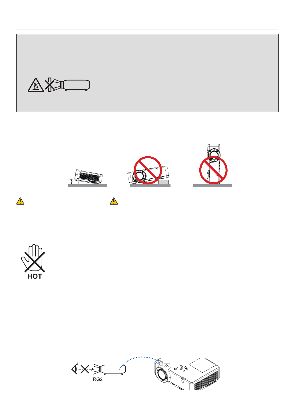
Place the projector in a horizontal position
Thetiltangleoftheprojectorshouldnotexceed10degrees,norshouldtheprojectorbeinstalledinanywayother
than the desktop and ceiling mount, otherwise lamp life could decrease dramatically.
10°
Fire and Shock Precautions
•Ensurethatthereissufcientventilationandthatventsareunobstructedtopreventthebuild-upofheatinside
your projector. Allow at least 4 inches (10 cm) of space between your projector and a wall.
•Donottrytotouchtheexhaustventasitcanbecomeheatedwhiletheprojectoristurnedonandimmediately
after the projector is turned off. Parts of the projector may become temporarily heated if the projector is turned off
with the POWER button or if the AC power supply is disconnected during normal projector operation.
Use caution when picking up the projector.
•Preventforeignobjectssuchaspaperclipsandbitsofpaperfromfallingintoyourprojector.Donotattemptto
retrieve any objects that might fall into your projector. Do not insert any metal objects such as a wire or screwdriver
into your projector. If something should fall into your projector, disconnect it immediately and have the object
removed by a qualified service personnel.
•Donotplaceanyobjectsontopoftheprojector.
•Donottouchthepowerplugduringathunderstorm.Doingsocancauseelectricalshockorre.
•Theprojectorisdesignedtooperateonapowersupplyof100-240VAC50/60Hz.Ensurethatyourpowersupply
fits this requirement before attempting to use your projector.
•Donotlookthelenswhiletheprojectorison.Seriousdamagetoyoureyescouldresult.Thefollowinglabel,that
isindicatednearthelens-mounting-sectionontheprojectorcabinet,describesthisprojectoriscategorizedinthe
riskgroup2ofIEC62471-5:2015.Aswithanybrightsource,donotstareintothebeam,RG2IEC62471-5:2015.

iv
Important Information
•Keepanyitemssuchasmagnifyingglassoutofthelightpathoftheprojector.Thelightbeingprojectedfromthe
lensisextensive,thereforeanykindofabnormalobjectsthatcanredirectlightcomingoutofthelens,cancause
unpredictable outcome such as fire or injury to the eyes.
•Donotplaceanyobjects,whichareeasilyaffectedbyheat,infrontofaprojectorexhaustvent.
Doing so could lead to the object melting or getting your hands burned from the heat that is emitted from the
exhaust.
•Donotsplashwaterovertheprojector.Doingsocancauseelectricalshockorre.Iftheprojectorgetswet,turn
off the projector, unplug the power cord and have the projector serviced by a qualified service personnel.
•Handlethepowercordcarefully.Adamagedorfrayedpowercordcancauseelectricshockorre.
- Do not use any power cord other than the one supplied with the projector.
-Donotbendortugthepowercordexcessively.
- Do not place the power cord under the projector, or any heavy object.
- Do not cover the power cord with other soft materials such as rugs.
- Do not heat the power cord.
- Do not handle the power plug with wet hands.
•Turnofftheprojector,unplugthepowercordandhavetheprojectorservicedbyaqualiedservicepersonnel
under the following conditions:
- When the power cord or plug is damaged or frayed.
-Ifliquidhasbeenspilledintotheprojector,orifithasbeenexposedtorainorwater.
- If the projector does not operate normally when you follow the instructions described in this user’s manual.
- If the projector has been dropped or the cabinet has been damaged.
-Iftheprojectorexhibitsadistinctchangeinperformance,indicatinganeedforservice.
•Disconnectthepowercordandanyothercablesbeforecarryingtheprojector.
•Turnofftheprojectorandunplugthepowercordbeforecleaningthecabinetorreplacingthelamp.
•Turnofftheprojectorandunplugthepowercordiftheprojectorisnottobeusedforanextendedperiodoftime.
•WhenusingaLANcable:
Forsafety,donotconnecttotheterminalforperipheraldevicewiringthatmighthaveexcessivevoltage.
CAUTION
•Donotusetheadjustabletiltfootforpurposesotherthanoriginallyintended.Misusessuchasgrippingthe
tilt-foot or hanging on the wall can cause damage to the projector.
•DonotturnofftheACpowerfor60secondsafterthelampisturnedonandwhilethePOWERindicatoris
blinking blue. Doing so could cause premature lamp failure.
Remote Control Precautions
•Handletheremotecontrolcarefully.
•Iftheremotecontrolgetswet,wipeitdryimmediately.
•Avoidexcessiveheatandhumidity.
•Donotshort,heat,ortakeapartbatteries.
•Donotthrowbatteriesintore.
•Ifyouwillnotbeusingtheremotecontrolforalongtime,removethebatteries.
•Ensurethatyouhavethebatteries’polarity(+/−)alignedcorrectly.
•Donotusenewandoldbatteriestogether,orusedifferenttypesofbatteriestogether.
•Disposeofusedbatteriesaccordingtoyourlocalregulations.
Note for Canadian Environmental Protection Act, 1999
The lamp(s) in this product contains mercury. Please dispose according to your local authority law.
FOR MORE INFORMATION, CONTACT:
NEC Display Solutions of America, Inc.
3250LaceyRd,Ste500
DownersGrove,IL60515
TELEPHONE630-467-4712
www.necdisplay.com
v
Important Information
Note for US Residents
The lamp in this product contains mercury. Please dispose according to Local, State or Federal Laws.
Lamp Replacement
•Usethespeciedlampforsafetyandperformance.
•Toreplacethelamp,followallinstructionsprovidedonpage
111.
•Besuretoreplacethelampandlterwhenthemessage[THE LAMP HAS REACHED THE END OF ITS USABLE
LIFE. PLEASE REPLACE THE LAMP AND FILTER.] appears. If you continue to use the lamp after the lamp has
reached the end of its usable life, the lamp bulb may shatter, and pieces of glass may be scattered in the lamp
case. Do not touch them as the pieces of glass may cause injury.
If this happens, contact your dealer for lamp replacement.
A Lamp Characteristic
The projector has a discharge lamp for special purposes as a light source.
A lamp has a characteristic that its brightness gradually decreases with age. Also repeatedly turning the lamp on
and off will increase the possibility of its lower brightness.
The actual lamp life may vary depending upon the individual lamp, the environmental conditions and usage.
CAUTION:
•DONOTTOUCHTHELAMPimmediatelyafterithasbeenused.Itwillbeextremelyhot.Turntheprojectoroff
and then disconnect the power cord. Allow at least one hour for the lamp to cool before handling.
•Whenremovingthelampfromaceiling-mountedprojector,makesurethatnooneisundertheprojector.Glass
fragments could fall if the lamp has been burned out.
About High Altitude mode
•Set[FANMODE]to[HIGHALTITUDE]whenusingtheprojectorataltitudesapproximately5500feet/1700meters
or higher.
Usingtheprojectorataltitudesapproximately5500feet/1700metersorhigherwithoutsettingto[HIGHALTITUDE]
can cause the projector to overheat and the protector could shut down. If this happens, wait a couple minutes
and turn on the projector.
•Usingtheprojectorataltitudeslessthanapproximately5500feet/1700metersandsettingto[HIGHALTITUDE]
cancausethelamptoovercool,causingtheimagetoicker.Switch[FANMODE]to[AUTO].
•Usingtheprojectorataltitudesapproximately5500feet/1700metersorhighercanshortenthelifeofoptical
components such as the lamp.
About Copyright of original projected pictures:
Please note that using this projector for the purpose of commercial gain or the attraction of public attention in a venue
suchasacoffeeshoporhotelandemployingcompressionorexpansionofthescreenimagewiththefollowing
functions may raise concern about the infringement of copyrights which are protected by copyright law.
[ASPECTRATIO],[KEYSTONE],Magnifyingfeatureandothersimilarfeatures.
Turkish RoHS information relevant for Turkish market
EEE Yonetmeliğine Uygundur.
This device is not intended for use in the direct field of view at visual display workplaces. To avoid incommoding
reectionsatvisualdisplayworkplacesthisdevicemustnotbeplacedinthedirecteldofview.

vi
Important Information
Power management function
The projector has power management functions. To reduce power consumption, the power management functions
(1and2)arefactorypresetasshownbelow.TocontroltheprojectorfromanexternaldeviceviaaLANorserial
cableconnection,usetheon-screenmenutochangethesettingsfor1and2.
1. STANDBY MODE (Factory preset: NORMAL)
To control the projector from an external device, select [NETWORK STANDBY] or [SLEEP] for [STANDBY MODE].
NOTE:
•When[NORMAL]isselectedfor[STANDBYMODE],thefollowingterminalsandfunctionswillnotwork:
COMPUTEROUTterminal,AUDIOOUTterminal,USB-Bport,LANfunctions,MailAlertfunction,DDC/CI(VirtualRemoteTool).Pleaserefer
topage71aboutdetails.
•When[NETWORKSTANDBY]hasbeensetfor[STANDBYMODE]andtheLANhasbeeninlink-downconditionfor3minutes,[STANDBY
MODE]willtransitinto[NORMAL]automaticallyforthepurposetosavetheconsumptionpower.
2. AUTO POWER OFF (Factory preset: 1 hour)
To control the projector from an external device, select [OFF] for [AUTO POWER OFF].
NOTE:
•When[1:00]isselectedfor[AUTOPOWEROFF],youcanenabletheprojectortoautomaticallyturnoffin60minutesifthereisnosignal
receivedbyanyinputorifnooperationisperformed.

vii
Table of Contents
Important Information ............................................................................................ i
1. Introduction .......................................................................................................... 1
❶What’sintheBox? ........................................................................................................ 1
❷ Introduction to the Projector ......................................................................................... 2
Features you’ll enjoy: .............................................................................................. 2
About this user’s manual ......................................................................................... 3
❸ Part Names of the Projector .......................................................................................... 4
Front/Top ................................................................................................................. 4
Rear ......................................................................................................................... 5
Top Features ............................................................................................................ 6
Terminal Panel Features .......................................................................................... 7
❹ Part Names of the Remote Control ............................................................................... 8
Battery Installation ................................................................................................... 9
Remote Control Precautions ................................................................................... 9
Operating Range for Wireless Remote Control ....................................................... 9
2. Projecting an Image (Basic Operation) .............................................. 10
❶ Flow of Projecting an Image ........................................................................................ 10
❷ Connecting Your Computer/Connecting the Power Cord .......................................... 11
❸ Turning on the Projector .............................................................................................. 12
Note on Startup screen (Menu Language Select screen) ...................................... 13
❹ Selecting a Source ...................................................................................................... 14
Selecting the computer or video source ................................................................ 14
❺AdjustingthePictureSizeandPosition ...................................................................... 15
Adjust the Tilt Foot................................................................................................. 16
Zoom...................................................................................................................... 17
Focus ..................................................................................................................... 17
❻CorrectingKeystoneDistortion[KEYSTONE] ............................................................. 18
❼OptimizingComputerSignalAutomatically ................................................................ 20
Adjusting the Image Using Auto Adjust ................................................................. 20
❽ Turning Up or Down Volume ....................................................................................... 20
❾ Turning off the Projector ............................................................................................. 21
❿ When Moving the Projector ......................................................................................... 22
3. Convenient Features ..................................................................................... 23
❶ Turning off the Image and Sound ................................................................................ 23
❷FreezingaPicture........................................................................................................ 23
❸ Magnifying a Picture .................................................................................................... 23
❹ Changing Eco Mode/Checking Energy-Saving Effect ............................................... 24
UsingEcoMode[ECOMODE] .............................................................................. 24
CheckingEnergy-SavingEffect[CARBONMETER] .............................................. 25
❺Using4-PointCornertoCorrectKeystoneDistortion[CORNERSTONE] ................... 26
Cornerstone ........................................................................................................... 26
Pincushion ............................................................................................................. 28
❻
PreventingtheUnauthorizedUseoftheProjector[SECURITY] ...................................... 30

viii
Table of Contents
❼
Operating Your Computer’s Mouse Functions from the Projector’s Remote Control
via the USB Cable (Remote Mouse Function) ................................................................33
❽ Projecting Your Computer’s Screen Image from the Projector via the USB Cable
(USB Display) .............................................................................................................. 34
9ProjectinganImagefromanAngle(GeometricCorrectionToolinImageExpress
Utility Lite) .................................................................................................................... 36
What you can do with GCT .................................................................................... 36
Projecting an Image from an Angle (GCT) ............................................................. 36
4. Using the VIEWER ........................................................................................... 38
❶ Things you can do with the VIEWER ........................................................................... 38
❷ Projecting the pictures on a USB memory (basic operation) ...................................... 39
3 Slide screen operations ............................................................................................... 43
4 File list screen operations ............................................................................................ 44
5 Option menu ................................................................................................................ 46
6 Changing the logo data (background image) .............................................................. 47
5. Using On-Screen Menu ................................................................................ 49
❶ Using the Menus ......................................................................................................... 49
❷ Menu Elements ............................................................................................................ 50
❸ List of Menu Items ....................................................................................................... 51
❹MenuDescriptions&Functions[INPUT] ..................................................................... 54
HDMI1andHDMI2 ................................................................................................ 54
COMPUTER ........................................................................................................... 54
VIDEO .................................................................................................................... 54
USB-A .................................................................................................................... 54
LAN ........................................................................................................................ 54
USB-B .................................................................................................................... 54
❺MenuDescriptions&Functions[ADJUST] .................................................................. 55
[PICTURE] .............................................................................................................. 55
[IMAGEOPTIONS] ................................................................................................. 58
[AUDIO] .................................................................................................................. 62
❻MenuDescriptions&Functions[SETUP] .................................................................... 63
[GENERAL]............................................................................................................. 63
[MENU]................................................................................................................... 65
[INSTALLATION] .................................................................................................... 67
[OPTIONS(1)] ......................................................................................................... 69
[OPTIONS(2)] ......................................................................................................... 71
❼MenuDescriptions&Functions[INFO.] ...................................................................... 74
[USAGETIME]........................................................................................................ 74
[SOURCE(1)] .......................................................................................................... 75
[SOURCE(2)] .......................................................................................................... 75
[WIREDLAN] .......................................................................................................... 75
[WIRELESSLAN] ................................................................................................... 76
[VERSION] .............................................................................................................. 76
[OTHERS] ............................................................................................................... 76
❽MenuDescriptions&Functions[RESET] .................................................................... 77
ReturningtoFactoryDefault[RESET] ................................................................... 77

ix
Table of Contents
6. Installation and Connections ................................................................... 78
❶ Setting Up the Screen and the Projector .................................................................... 78
ThrowDistanceandScreenSize ........................................................................... 85
❷ Making Connections ................................................................................................... 88
Connecting Your Computer ................................................................................... 88
ConnectinganExternalMonitor ............................................................................ 90
Connecting Your DVD Player or Other AV Equipment .......................................... 91
Connecting Component Input ............................................................................... 92
Connecting HDMI Input ......................................................................................... 93
Connecting to a Wired LAN ................................................................................... 94
Connecting to a Wireless LAN (Optional: NP05LM series) .................................... 95
7. Connecting to a Network ............................................................................ 96
1 Things you can do by connecting the projector to a network..................................... 96
2 Connecting to MultiPresenter ..................................................................................... 97
3 NETWORK SETTINGS ................................................................................................ 99
4 Controlling the Projector by Using an HTTP Browser ............................................... 104
8. Maintenance .................................................................................................... 108
❶ Cleaning the Filter ..................................................................................................... 108
❷ Cleaning the Lens ...................................................................................................... 110
❸ Cleaning the Cabinet ................................................................................................. 110
❹ Replacing the Lamp and the Filter ............................................................................ 111
9. Appendix ............................................................................................................. 116
❶ Troubleshooting ........................................................................................................ 116
Feature of each indicator ..................................................................................... 116
Indicator Message (Status message) .................................................................. 116
Indicator Message (Error message) ..................................................................... 117
ExplanationonthePOWERindicatorandstandbystate .................................... 118
Common Problems & Solutions .......................................................................... 120
If there is no picture, or the picture is not displayed correctly. ........................... 121
❷ Specifications ............................................................................................................ 122
❸ Cabinet Dimensions .................................................................................................. 124
❹ Pin Assignments of D-Sub COMPUTER Input Terminal ........................................... 126
❺ Compatible Input Signal List ..................................................................................... 127
❻ PC Control Codes and Cable Connection ................................................................ 128
❼ Using the Computer Cable (VGA) to Operate the Projector (Virtual Remote Tool) ... 130
❽ Troubleshooting Check List ...................................................................................... 132
❾REGISTERYOURPROJECTOR!(forresidentsintheUnitedStates,Canada,and
Mexico) ...................................................................................................................... 134
1
Projector
1. Introduction
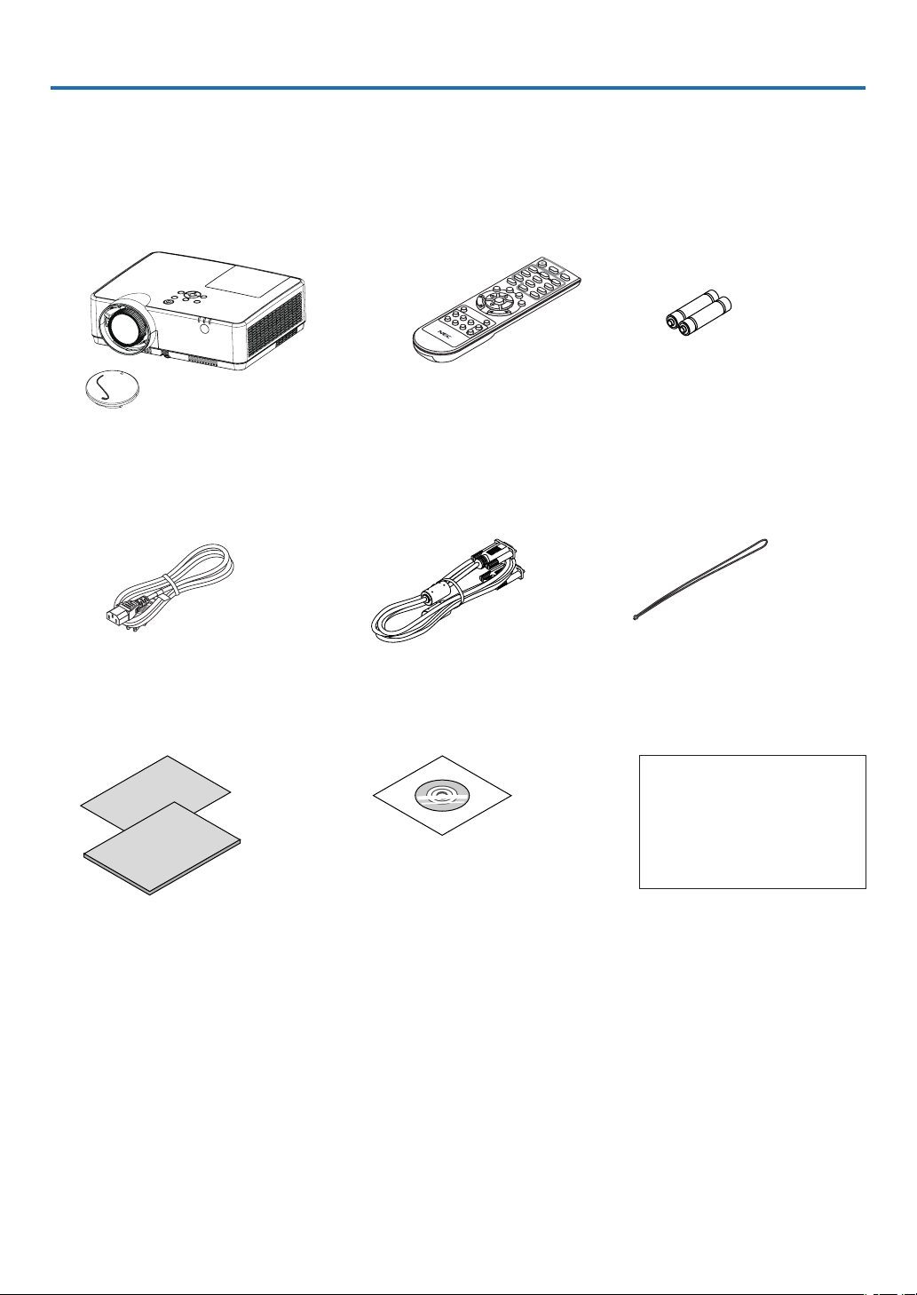
❶ What’s in the Box?
Make sure your box contains everything listed. If any pieces are missing, contact your dealer.
Please save the original box and packing materials if you ever need to ship your projector.
Power cord
(US: 7N080242)
(EU: 7N080028)
Lens cap (24F55631)
Lens cap strap × 1 (24J23901)
Computer cable (VGA)
(7N520089)
Strap × 1
(24J41711)
NEC Projector CD-ROM
User’s manual (PDF)
(7N952821)
For North America only
Limited warranty
For customers in Europe:
You will find our current valid
Guarantee Policy on our Web
Site:
www.nec-display-solutions.com
•ImportantInfomation(7N8N9391)
•QuickSetupGuide(UG)(7N8N9381)
QuickSetupGuide(G2)(7N8N9431)
Remote control
(7N901171)
Batteries (AAA × 2)
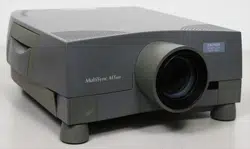
Unless otherwise described in the user’s manual, the drawings for the projector cabinet show examples of the ME382U.

2
1. Introduction
❷ Introduction to the Projector
This section introduces you to your new projector and describes the features and controls.
Features you’ll enjoy:
•QuickPowerOff,DirectPowerOff
The projector can be put away immediately after the projector is powered down. No cool down period is required
after the projector is turned off from the remote control or cabinet control panel.
The projector has a feature called “Direct Power Off”. This feature allows the projector to be turned off (even
when projecting an image) by using the Main Power Switch or disconnecting the AC power supply.
To turn off the AC power supply when the projector is powered on, use a power strip equipped with a switch and
a breaker.
•0.18W(100-130VAC)/0.26W(200-240VAC)instandbyconditionwithenergysavingtechnology
Selecting [NORMAL] for [STANDBY MODE] from the menu can put the projector in power-saving mode that
consumes only 0.18W(100-130 V AC)/0.26W (200-240 V AC).
•CarbonMeter
This feature will show energy-saving effect in terms of CO
2
emission reduction (kg) when the projector’s [ECO
MODE] is set to [AUTO ECO], [NORMAL], or [ECO].
The amount of CO
2
emission reduction will be displayed in the confirmation message at the time of power-off
and in the INFO of the on-screen menu.
•Lamplifeupto15000hours
Using in Eco Mode (ECO) allows you to prolong the projector’s lamp life up to 15000 hours (up to 10000 hours
in ECO MODE OFF).
•TwoHDMIinputssupportdigitalsignals
The two HDMI inputs provide HDCP compatible digital signals. The HDMI input also supports audio signal.
•IntegratedRJ-45terminalforwirednetworkingcapabilityalongwithwirelessnetworkingcapabilities
An RJ-45 terminal is standard. An optional USB Wireless LAN Unit is required for wireless LAN connection.
•INTELLIGENTCONNECTION
It enables easily to connect your projector to computers or smartphones, on which the application software,
MultiPresenter, has been installed, by inputting PIN code.
•16Wbuilt-inspeakerforanintegratedaudiosolution
Powerful 16 watt monaural speaker provides volume need for large rooms.
•ThesuppliedremotecontrolallowsyoutoassignaCONTROLIDtotheprojector
Multiple projectors can be operated separately and independently with the same single remote control by as-
signing an ID number to each projector.
•USBDisplay
Using a commercially available USB cable (compatible with USB 2.0 specifications) to connect the computer with
the projector allows you to send your computer screen image to the projector without the need of a traditional
computer cable (VGA).

3
1. Introduction
•Convenientutilitysoftware(UserSupportware)
This projector supports our utility software (NaViSet Administrator 2, Virtual Remote Tool, etc.) NaViSet Adminis-
trator 2 helps you control the projector by a computer via wired LAN connection. Virtual Remote Tool helps you
perform operations by a virtual remote control such as projector's power on or off and signal selection via wired
LAN connection. Moreover, it has function to send an image to the projector and register it as the logo data.
Image Express Utility Lite (for Windows) can be started from a commercially available USB memory or SD card
without the need of installing on your computer.
Please visit our web site for downloading each software.
URL:
https://www.nec-display.com/dl/en/index.html
•AUTOPOWERONandAUTOPOWEROFFfeatures
The DIRECT POWER ON, AUTO POWER ON, AUTO POWER OFF, and OFF TIMER features eliminate the need
to always use the POWER button on the remote control or projector cabinet.
•Preventingunauthorizeduseoftheprojector
Enhanced smart security settings for keyword protection, cabinet control panel lock, security slot, and security
chain opening to help prevent unauthorized access, adjustments and theft deterrence.
•HighresolutionuptoWUXGA*
1
High resolution display - up to WUXGA compatible, XGA (ME402X/MC422X/MC372X/MC342X/MC302X) / WXGA
(ME372W/MC382W/MC332W) / WUXGA (ME382U/ME342U) native resolution.
•Animagewithhigherorlowerresolutionthantheprojector’snativeresolution(ME402X/MC422X/MC372X/
MC342X/MC302X: 1024 × 768 / ME372W/MC382W/MC332W: 1280 × 800 / ME382U/ME342U: 1920 × 1200)
will be displayed with Advanced AccuBlend.
*
1
When WXGA MODE is set to ON.
•CRESTRONROOMVIEWcompatibility
The projector supports CRESTRON ROOMVIEW, allowing multiple devices connected in the network to be man-
aged and controlled from a computer or controller.
About this user’s manual
The fastest way to get started is to take your time and do everything right the first time. Take a few minutes now to
review the user’s manual. This may save you time later on. At the beginning of each section of the manual you’ll find
an overview. If the section doesn’t apply, you can skip it.
4
1. Introduction
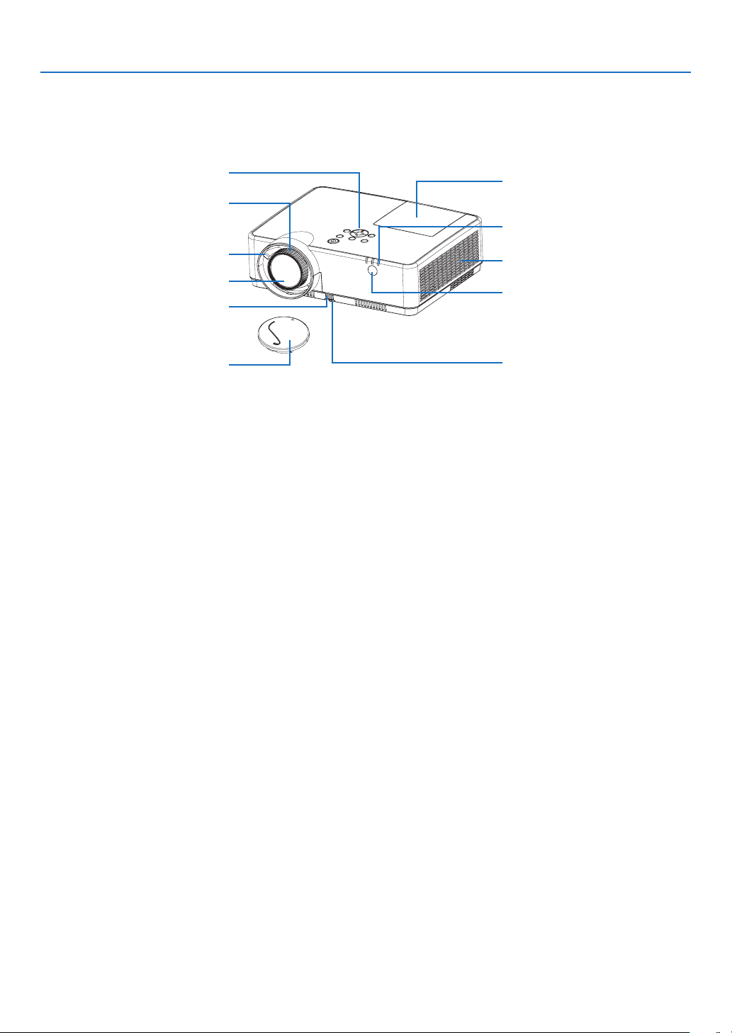
❸ Part Names of the Projector
Front/Top
Controls
(→ page
6)
Remote Sensor
(→ page
9)
Exhaust Vent
Heatedairisexhaustedfromhere.
Indicators
(→ page
6)
Zoom Lever
(→ page 17)
Lens Cap
For protecting lens.
Makesuretotakeitoffduring
projection.
Focus Ring
(→ page
17)
Adjustable Tilt Foot
(→ page
16)
Lamp Cover
(→ page
112)
Adjustable Tilt Foot Lever
(→ page
16)
Lens
5
1. Introduction
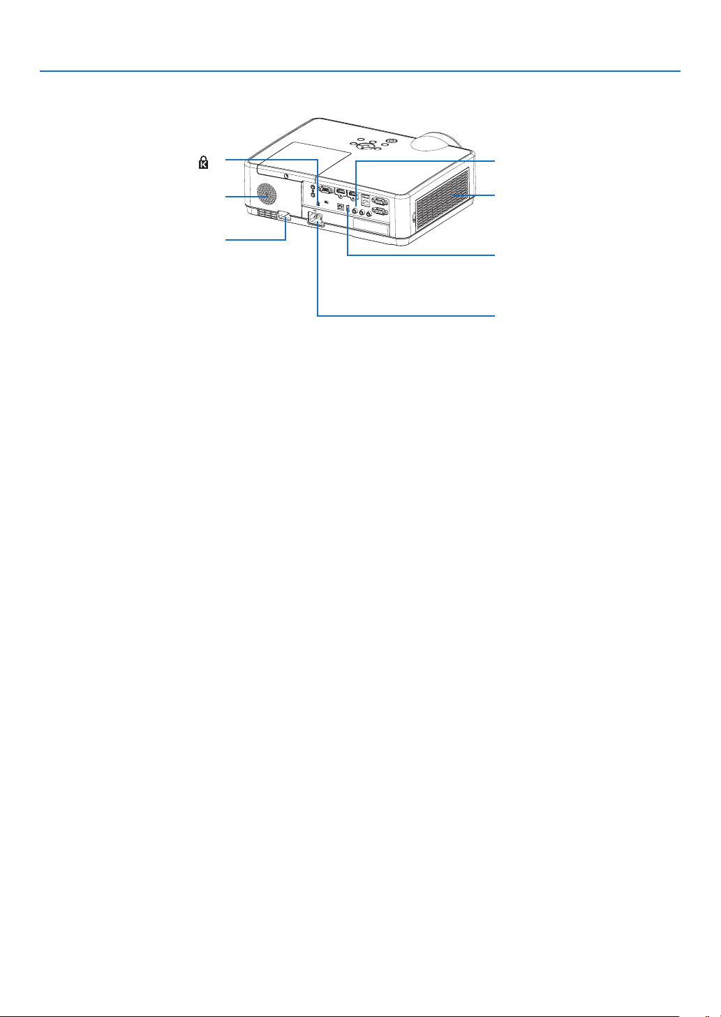
Rear
ACInput
Connect the supplied power cord’s
three-pin plug here, and plug the
other end into an active wall outlet.
(→ page
11)
Asthetheftanddropping-off
prevention measure, fix on the
supplied strap.
MonauralSpeaker(16W)
Terminal Panel
(→ page
7)
IntakeVent/FilterCover
(→ page
108, 114)
Built-in Security Slot (
)*
Security chain opening
Attachananti-theftdevice.
The security chain opening accepts
security wires or chains up to
0.18inch/4.6mmindiameter.
* This security slot supports the MicroSaver
®
Security System.
6
1. Introduction
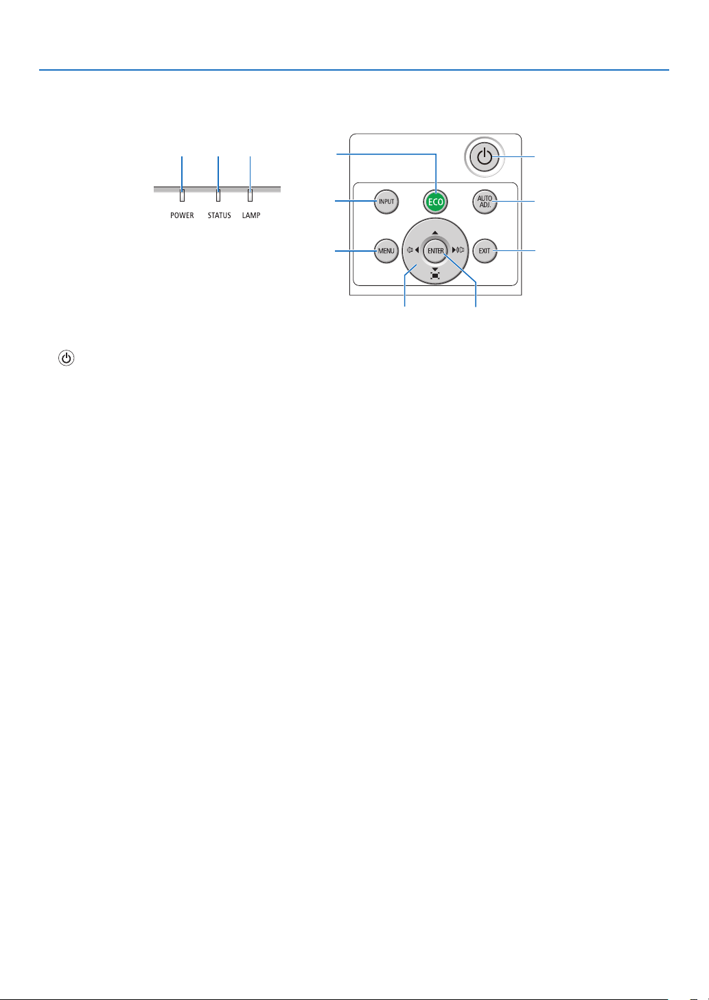
Top Features
7
9
11
10
2
3 4
6
8
1
5
1.(POWER)Button
(→ page
12, 21)
2.POWERIndicator
(→ page
11, 12, 21, 116)
3.STATUSIndicator
(→ page
116)
4.LAMPIndicator
(→ page
111, 116)
5.ECOButton
(→ page
24)
6.INPUTButton
(→ page
14)
7.AUTOADJ.Button
(→ page
20)
8.MENUButton
(→ page
49)
9.▲▼◀▶/VolumeButtons◀▶/KeystoneButtons
(→ page
18, 20, 26, 49)
10.ENTERButton
(→ page
49)
11.EXITButton
(→ page
49)
7
1. Introduction
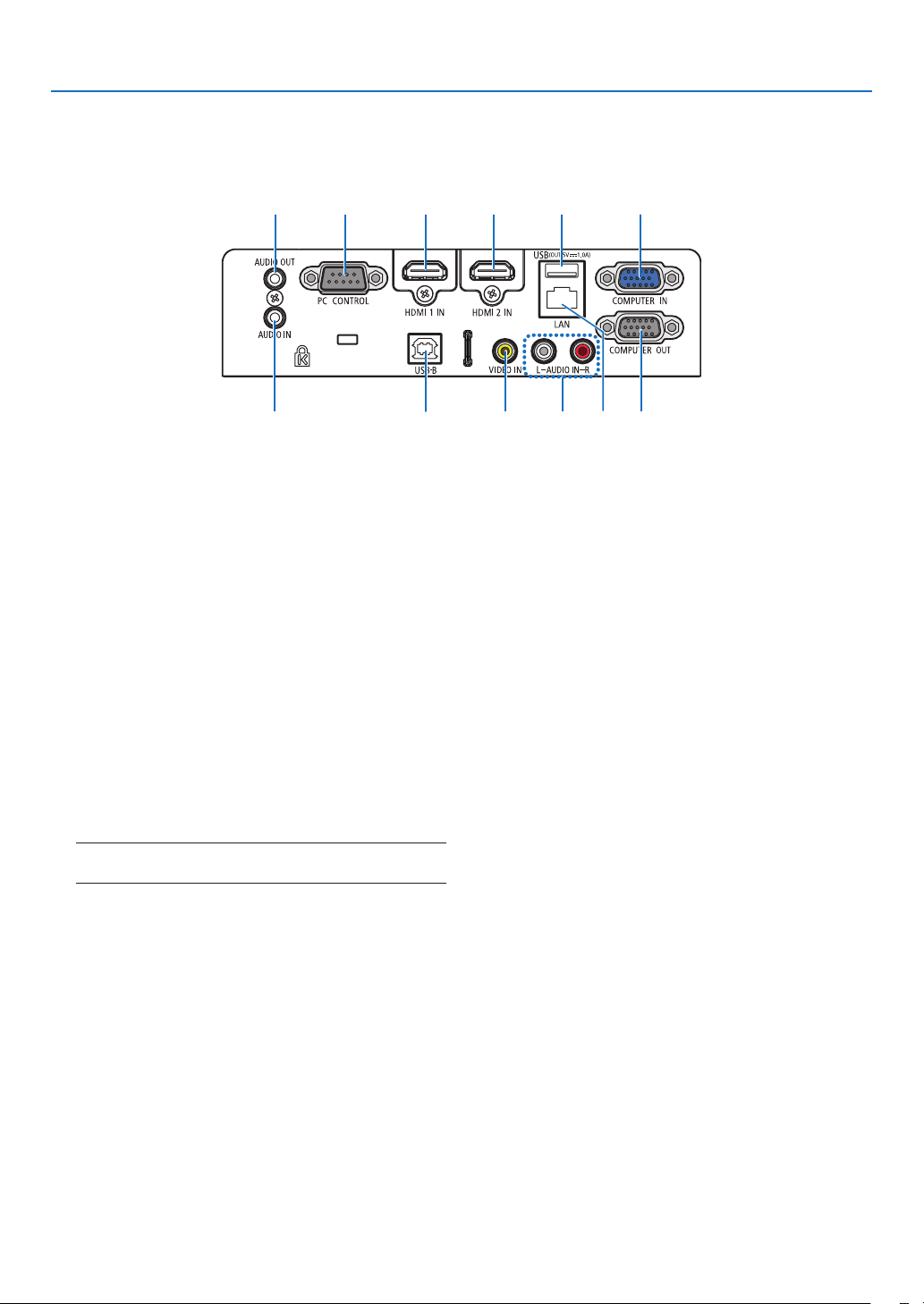
Terminal Panel Features
1.COMPUTERIN/ComponentInputTerminal
(MiniD-Sub15Pin)
(→ page
11, 88, 92)
2.COMPUTERAUDIOINMiniJack(StereoMini)
(→ page
88, 92)
3.HDMI1INTerminal(TypeA)
(→ page
88, 89, 93)
4.HDMI2INTerminal(TypeA)
(→ page
88, 89, 93)
5.USBPort(TypeB)
(→ page
33, 34, 88)
6.COMPUTEROUTTerminal(MiniD-Sub15Pin)
(→ page
90)
7.AUDIOOUTMiniJack(StereoMini)
(→ page
90)
NOTE: The AUDIO OUT mini jack does not support earphone/
headphone terminal.
8.VIDEOINTerminal(RCA)
(→ page
91)
9.VIDEOAUDIOINL/MONO,R(RCA)
(→ page
91)
10.LANPort(RJ-45)
(→ page
94)
11.USBPort(TypeA)
ForUSBmemoryoroptionalWirelessLANunit
(→ page
39, 95)
12.PCCONTROLPort(D-Sub9Pin)
(→ page
128)
Use this port to connect a PC or control system.
This enables you to control the projector using serial
communication protocol. If you are writing your own
program, typical PC control codes are on page 128.
1
7123411
5910 682
8
1. Introduction
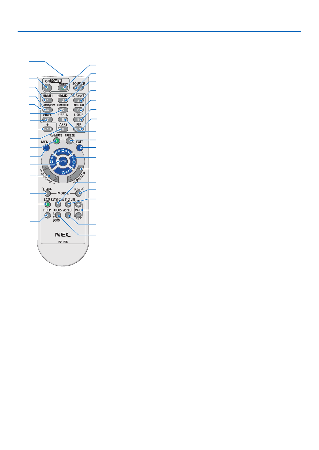
❹ Part Names of the Remote Control
6
1
15
17
31
32
33
21
22
27
29
30
26
25
24
23
28
34
20
19
12
11
3
4
7
2
9
5
8
14
18
10
13
16
1.InfraredTransmitter
(→ page
9)
2.POWERONButton
(→ page
12)
3.POWERSTANDBYButton
(→ page
21)
4.SOURCEButton
(→ page
14)
5.HDMI1Button
(→ page
14)
6.HDMI2Button
(→ page
14)
7.HDBaseTButton
(This button does not work on this
series of projectors)
8.DisplayPortButton
(This button does not work on this
series of projectors)
9.COMPUTERButton
(→ page
14)
10.AUTOADJ.Button
(→ page
20)
11.VIDEOButton
(→ page
14)
12.USB-AButton
(→ page
14, 39, 54)
13.USB-BButton
(→ page
14, 33, 54, 88)
14.APPSButton
(→ page
14)
15.IDSETButton
(→ page
68)
16.NumericKeypadButton/
CLEARButton
(→ page
68)
17.PIPButton
(PIP button does not work on this
series of projectors)
18.FREEZEButton
(→ page
23)
19.AV-MUTEButton
(→ page
23)
20.MENUButton
(→ page
49)
21.EXITButton
(→ page
49)
22.▲▼◀▶Button
(→ page
49)
23.ENTERButton
(→ page
49)
24.D-ZOOM(+)(–)Button
(→ page
23, 24)
25.MOUSEL-CLICKButton*
(→ page
33)
26.MOUSER-CLICKButton*
(→ page
33)
27.PAGE▽/△Button
(→ page
33)
28.ECOButton
(→ page
24)
29.KEYSTONEButton
(→ page
18, 26)
30.PICTUREButton
(→ page
55, 57)
31.VOL.(+)(–)Button
(→ page
20)
32.ASPECTButton
(→ page
60)
33.FOCUS/ZOOMButton
(This button does not work on this
series of projectors)
34.HELPButton
(→ page
74, 77, 113)
* The MOUSE L-CLICK and MOUSE R-CLICK buttons work only when a USB cable is connected with your computer.
9
1. Introduction
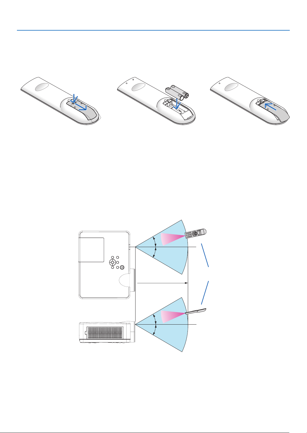
Battery Installation
1. Press firmly and slide the bat-
tery cover off.
2. Install new batteries (AAA).
Ensure that you have the bat-
teries’ polarity (+/−) aligned
correctly.
3. Slip the cover back over the
batteries until it snaps into
place. Do not mix different
types of batteries or new and
old batteries.
OPEN
OPEN
Remote Control Precautions
•Handletheremotecontrolcarefully.
•Iftheremotecontrolgetswet,wipeitdryimmediately.
•Avoidexcessiveheatandhumidity.
•Donotshort,heat,ortakeapartbatteries.
•Donotthrowbatteriesintore.
•Ifyouwillnotbeusingtheremotecontrolforalongtime,removethebatteries.
•Ensurethatyouhavethebatteries’polarity(+/−)alignedcorrectly.
•Donotusenewandoldbatteriestogether,orusedifferenttypesofbatteriestogether.
•Disposeofusedbatteriesaccordingtoyourlocalregulations.
Operating Range for Wireless Remote Control
30°
30°
30°
30°
22feet/7m
Remote control
•Theinfraredsignaloperatesbyline-of-sightuptoadistanceofabout22feet/7mandwithina60-degreeangle
of the remote sensor on the projector cabinet.
•Theprojectorwillnotrespondifthereareobjectsbetweentheremotecontrolandthesensor,orifstronglight
falls on the sensor. Weak batteries will also prevent the remote control from properly operating the projector.

10
This section describes how to turn on the projector and to project a picture onto the screen.
❶ Flow of Projecting an Image
Step 1
•Connectingyourcomputer/Connectingthepowercord(→ page
11)
Step 2
•Turningontheprojector(→ page
12)
Step 3
•Selectingasource(→ page
14)
Step 4
•Adjustingthepicturesizeandposition(→ page
15)
•Correctingkeystonedistortion[KEYSTONE](→ page
18)
Step 5
•Adjustingapictureandsound
- Optimizing a computer signal automatically (→ page
20)
- Turning up or down volume (→ page
20)
Step 6
•Makingapresentation
Step 7
•Turningofftheprojector(→ page
21)
Step 8
•WhenMovingtheProjector(→ page
22)
2. Projecting an Image (Basic Operation)
11
2. Projecting an Image (Basic Operation)
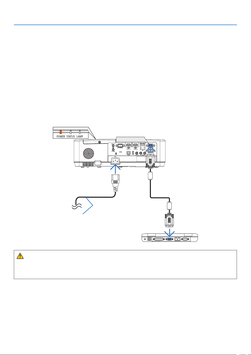
❷ Connecting Your Computer/Connecting the Power Cord
1.Connectyourcomputertotheprojector.
Thissectionwillshowyouabasicconnectiontoacomputer.Forinformationaboutotherconnections,see
“6.InstallationandConnections”onpage
88.
Connectthecomputercable(VGA)betweentheprojector’sCOMPUTERINterminalandthecomputer’sport(mini
D-Sub15Pin).Turntwothumbscrewsofbothterminalstoxthecomputercable(VGA).
2.Connectthesuppliedpowercordtotheprojector.
Firstconnectthesuppliedpowercord’sthree-pinplugtotheACINoftheprojector,andthenconnecttheother
plugofthesuppliedpowercordinthewalloutlet.
Theprojector’spowerindicatorwillstartblinkingorange.
*Thiswillapplyforbothindicatorswhen[NORMAL]isselectedfor[STANDBYMODE].SeethePowerIndicator
section. (→ page
116)
COMPUTER IN
Makesurethattheprongsarefully
insertedintoboththeACINandthe
wall outlet.
→ To wall outlet
CAUTION:
Parts of the projector may become temporarily heated if the projector is turned off with the POWER button or if
the AC power supply is disconnected during normal projector operation.
Be careful to handle the projector.
12
2. Projecting an Image (Basic Operation)
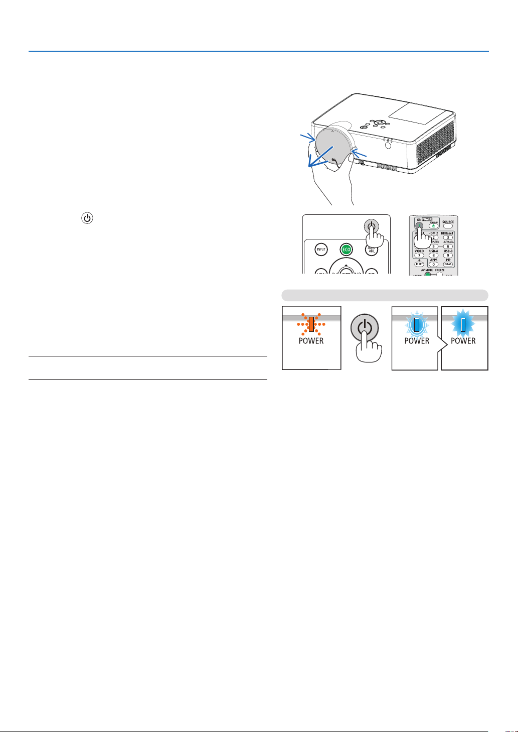
❸ Turning on the Projector
1. Remove the lens cap.
Pressandholdbothendsofthelenscapandpullittoward
you.
2. Press the (POWER)buttonontheprojectorcabinet
orthePOWERONbuttonontheremotecontrol.
ThePOWERindicatorwillblinkandtheprojectorwill
become ready to use.
TIP:
•Whenthemessage“Projectorislocked!Enteryourpassword.”
isdisplayed,itmeansthatthe[SECURITY]featureisturnedon.
(→page
31)
Afteryouturnonyourprojector,ensurethatthecomputer
or video source is turned on.
NOTE:Whennoinputsignalispresent,theno-signalguidanceisdisplayed
(factorymenusetting).
(→ page 116)
Standby Blinking Power On
Blinking orange light Blinking blue
light
Steady blue
light
13
2. Projecting an Image (Basic Operation)
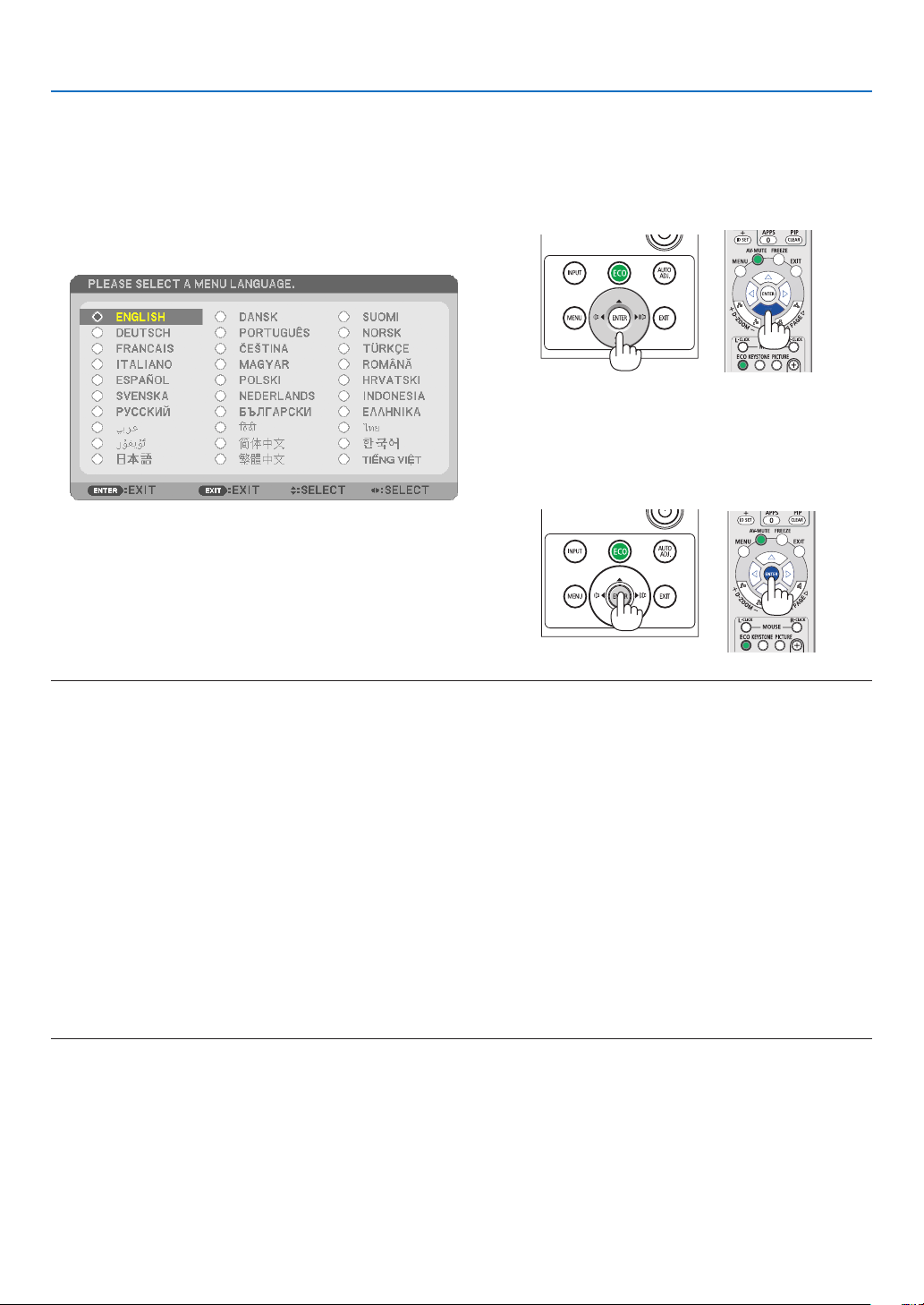
Note on Startup screen (Menu Language Select screen)
When you first turn on the projector, you will get the Startup menu. This menu gives you the opportunity to select
one of the 30 menu languages.
Toselectamenulanguage,followthesesteps:
1. Use the ▲, ▼, ◀ or ▶ button to select one of the 30
languages from the menu.
2.PresstheENTERbuttontoexecutetheselection.
After this has been done, you can proceed to the menu
operation.
If you want, you can select the menu language later.
(→ [LANGUAGE] on page
51 and 65)
NOTE:
•IftheprojectorisshutoffbyDIRECTPOWEROFF(pullingoutthepowercord)duringprojection,waitfor1secondatleastforreconnect
thepowercordforturningontheprojector.
Failingtodosocouldresultinnopowertotheprojector.(Therewillbenostand-byLED)
Shouldthishappen,unplugthepowercordandplugitinagain.Turnonthemainpower.
•Ifoneofthefollowingthingshappens,theprojectorwillnotturnon.
-Iftheinternaltemperatureoftheprojectoristoohigh,theprojectordetectsabnormalhightemperature.Inthiscondition,theprojector
willnotturnontoprotecttheinternalsystem.Ifthishappens,waitfortheprojector’sinternalcomponentstocooldown.
-Whenthelampreachesitsendofusablelife,theprojectorwillnotturnon.Ifthishappens,replacethelamp.
-IftheSTATUSindicatorlightsorangewiththepowerbuttonpressed,itmeansthatthe[CONTROLPANELLOCK]isturnedon.Cancel
thelockbyturningitoff.(→page
67)
-Ifthelampfailstolight,andifthePOWERindicatorblinksinredandtheLAMPindicatorlightsinred,waitafullminuteandthenturn
onthepower.
•WhilethePOWERindicatorisblinkingblueinshortcycles,thepowercannotbeturnedoffbyusingthepowerbutton.
•Immediatelyafterturningontheprojector,screenickermayoccur.Thisisnormal.Wait3to5minutesuntilthelamplightingisstabilized.
•Whentheprojectoristurnedon,itmaytakesometimebeforethelamplightbecomesbright.
•Ifyouturnontheprojectorimmediatelyafterthelampisturnedofforwhenthelamptemperatureishigh,thefansrunwithoutdisplaying
animageforsometimeandthentheprojectorwilldisplaytheimage.
14
2. Projecting an Image (Basic Operation)
❹ Selecting a Source
Selecting the computer or video source
NOTE: Turn on the computer or video source equipment connected to the projector.
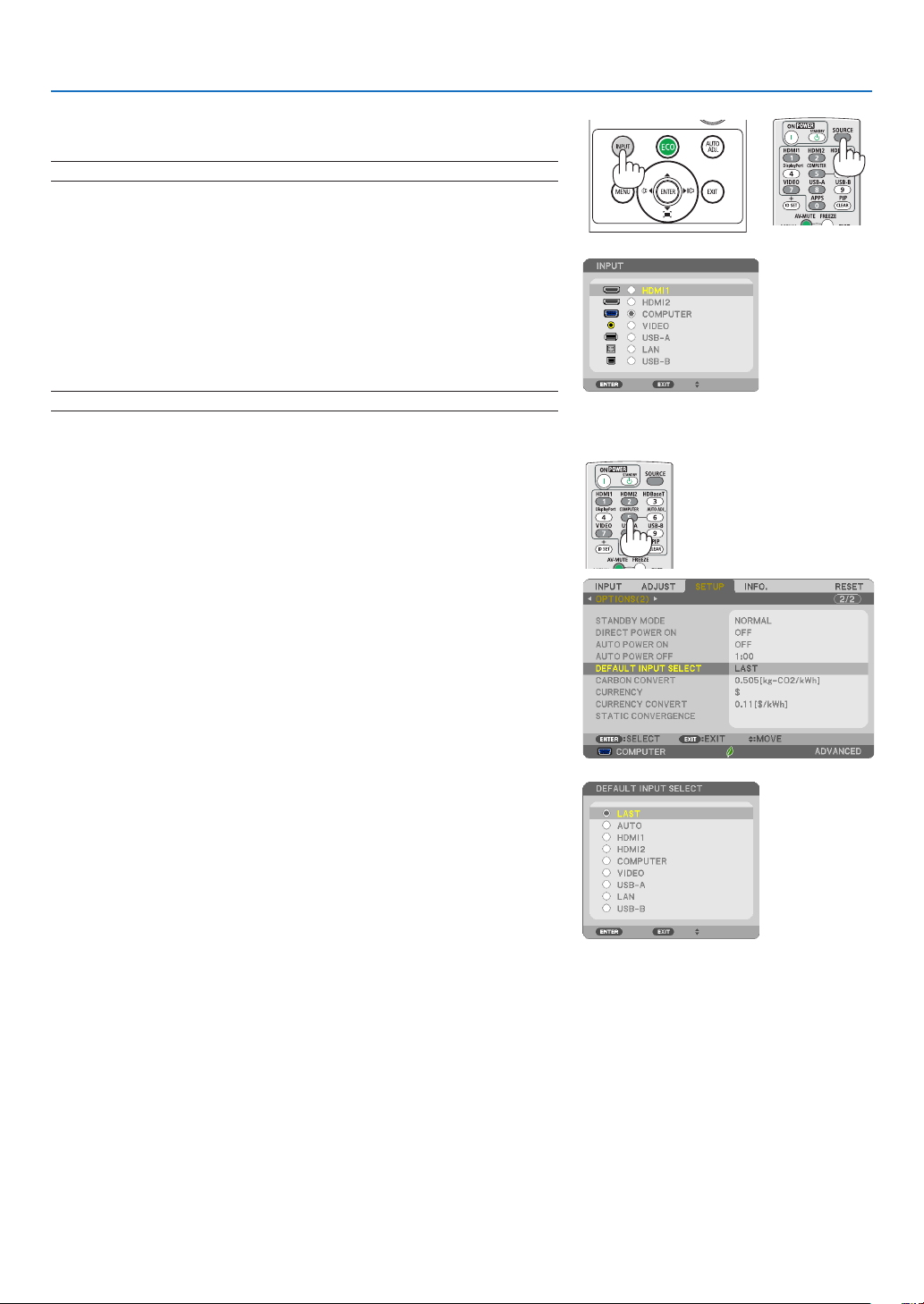
DetectingtheSignalAutomatically
Press the INPUT button once. The projector will search for the available
input source and display it. The input source will change as follows:
HDMI1 → HDMI2 → COMPUTER → VIDEO → USB-A → LAN → USB-B
•WiththeINPUTscreendisplayed,youcanpresstheINPUTbutton
a few times to select the input source.
TIP:Ifnoinputsignalispresent,theinputwillbeskipped.
UsingtheRemoteControl
Press any one of the COMPUTER, HDMI1, HDMI2, VIDEO, USB-A,
USB-B, or APPS buttons.
SelectingDefaultSource
You can so that it will be displayed each time the projector is turned on.
1.PresstheMENUbutton.
The menu will be displayed.
2. Press the ▶buttontwicetoselect[SETUP]andthe▼ button or
theENTERbuttontoselect[GENERAL].
3.
Press the
▶
buttonfourtimestoselect[OPTIONS(2)].
4. Press the ▼buttonvetimestoselect[DEFAULTINPUTSELECT]
andpresstheENTERbutton.
The[DEFAULTINPUTSELECT]screenwillbedisplayed.
(→ page
73)
5.
Selectasourceasthedefaultsource,andpresstheENTERbutton.
6.PresstheEXITbuttonafewtimestoclosethemenu.
7.Restarttheprojector.
The source you selected in step 5 will be projected.
TIP:
•WhentheprojectorisinStandbymode,applyingacomputersignalfromacomputer
connectedtotheCOMPUTERINinputwillpowerontheprojectorandsimultaneously
projectthecomputer’simage.
([AUTOPOWERON]→page
72)
•OnWindows7,acombinationoftheWindowsandPkeysallowsyoutosetupexternal
displayeasilyandquickly.
15
2. Projecting an Image (Basic Operation)
❺ Adjusting the Picture Size and Position
Use the adjustable tilt foot, the zoom function or the focus ring to adjust the picture size and position.
Inthischapterdrawingsandcablesareomittedforclarity.
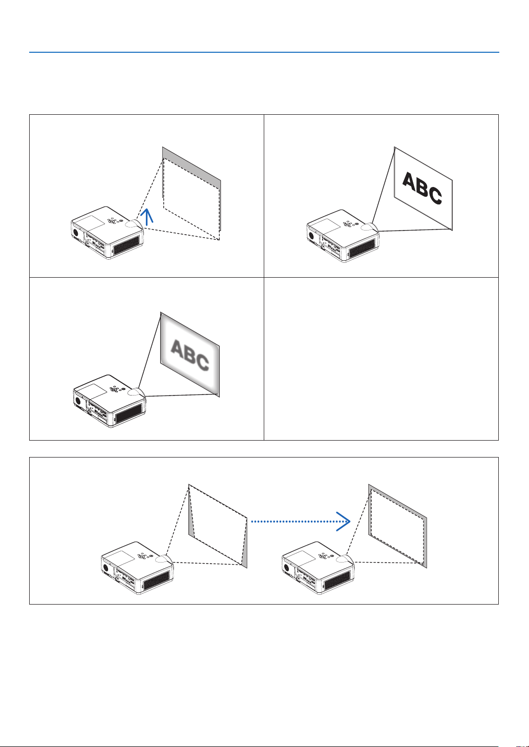
Adjusting the throw angle (the height of an image)
[Tilt foot] (→ page 16)
Finely adjusting the size of an image
[Zoom lever] (→ page 17)
Adjusting the focus
[Focus ring] (→ page 17)
Adjusting the keystone correction [KEYSTONE]* (→ page 18)
Automatic Keystone Correction function is turned on at the time of shipment.
To perform keystone correction manually, see “6. Correcting Keystone Distortion [KEYSTONE]” on page 18.
16
2. Projecting an Image (Basic Operation)
2
1
3
Adjustable Tilt FootAdjustable Tilt
Foot Lever
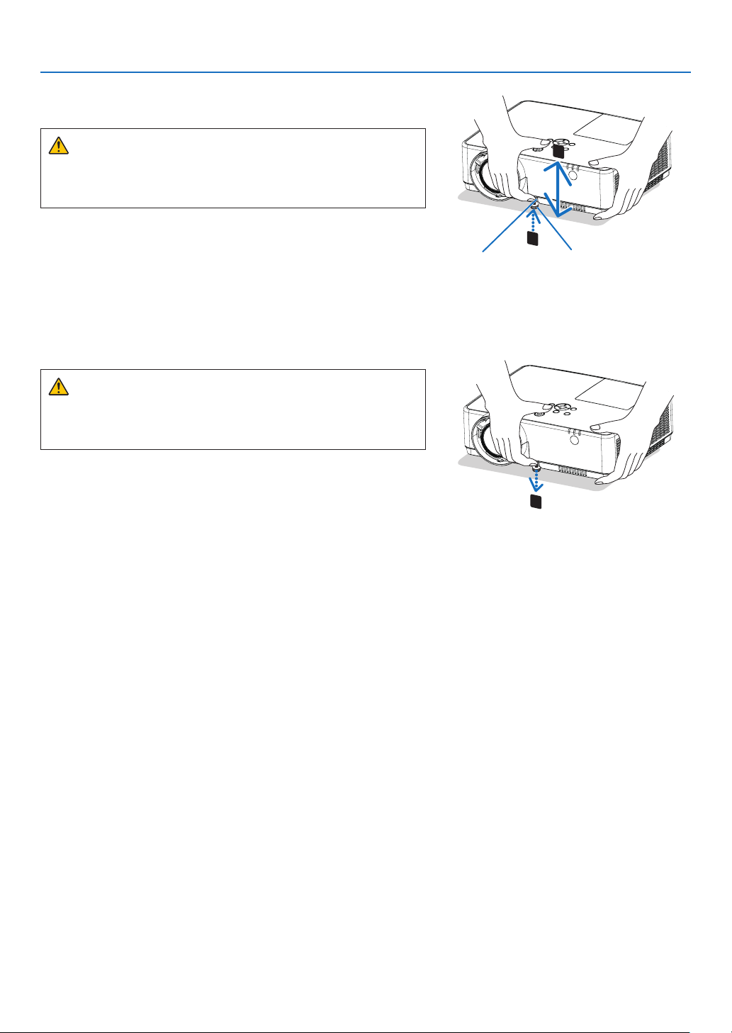
Adjust the Tilt Foot
1.Liftthefrontedgeoftheprojector.
CAUTION:
Do not try to touch the exhaust vent during Tilt Foot adjustment
as it can become heated while the projector is turned on and after
it is turned off.
2.PushupandholdtheAdjustableTiltFootLeveronthefront
oftheprojectortoextendtheadjustabletiltfoot.
3.Lowerthefrontoftheprojectortothedesiredheight.
4.ReleasetheAdjustableTiltFootLevertolocktheAdjustable
tilt foot.
Thetiltfootcanbeextendedupto1.6inch/40mm.
Thereisapproximately10degrees(up)ofadjustmentforthefront
oftheprojector.
CAUTION:
•Donotusethetilt-footforpurposesotherthanoriginallyintended.
Misuses such as using the tilt foot to carry or hang (from the wall
or ceiling) the projector can cause damage to the projector.
17
2. Projecting an Image (Basic Operation)
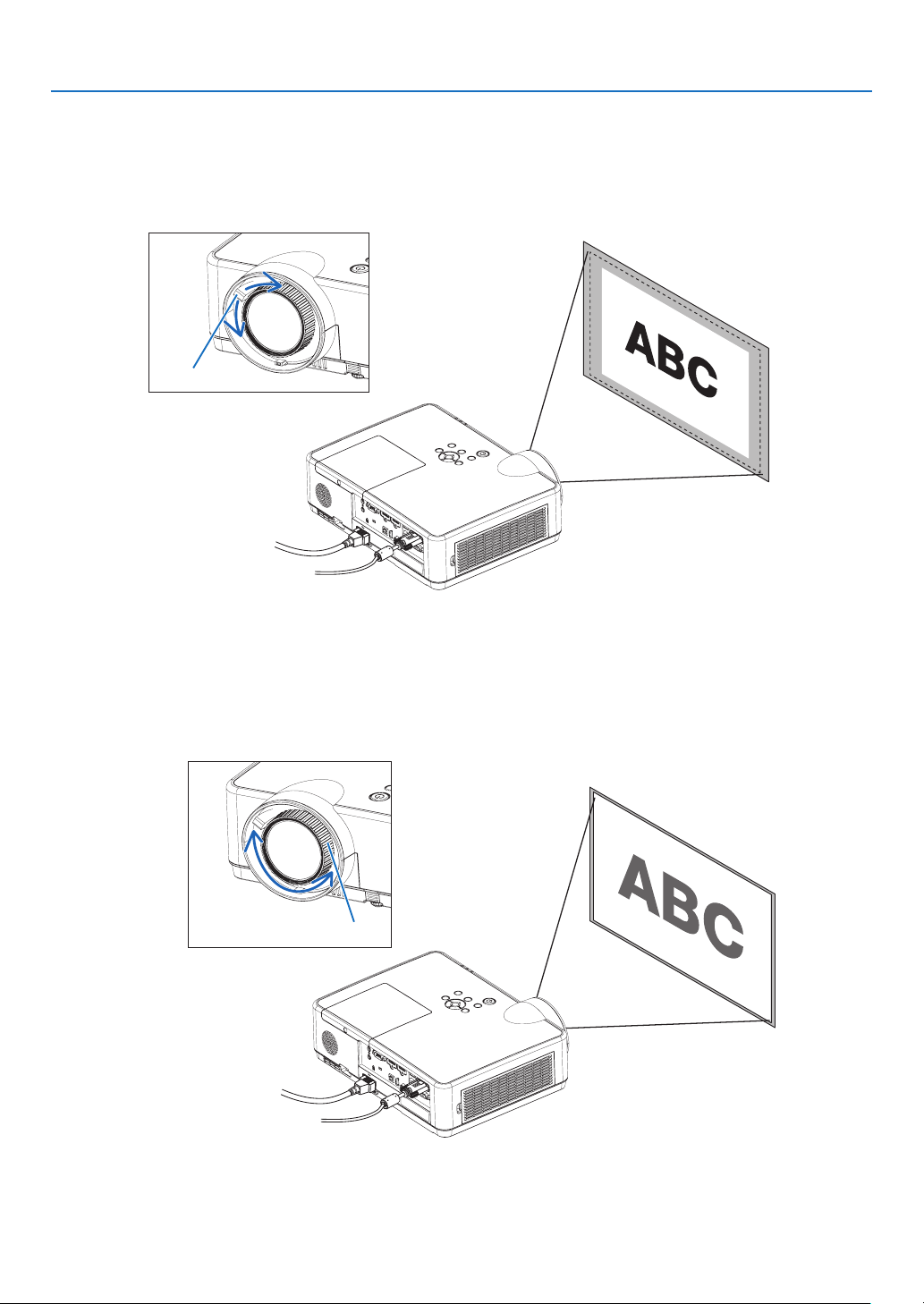
Zoom
Use the ZOOM lever to adjust the image size on the screen.
Zoom Lever
Focus
Use the FOCUS ring to obtain the best focus.
Focus Ring
18
2. Projecting an Image (Basic Operation)
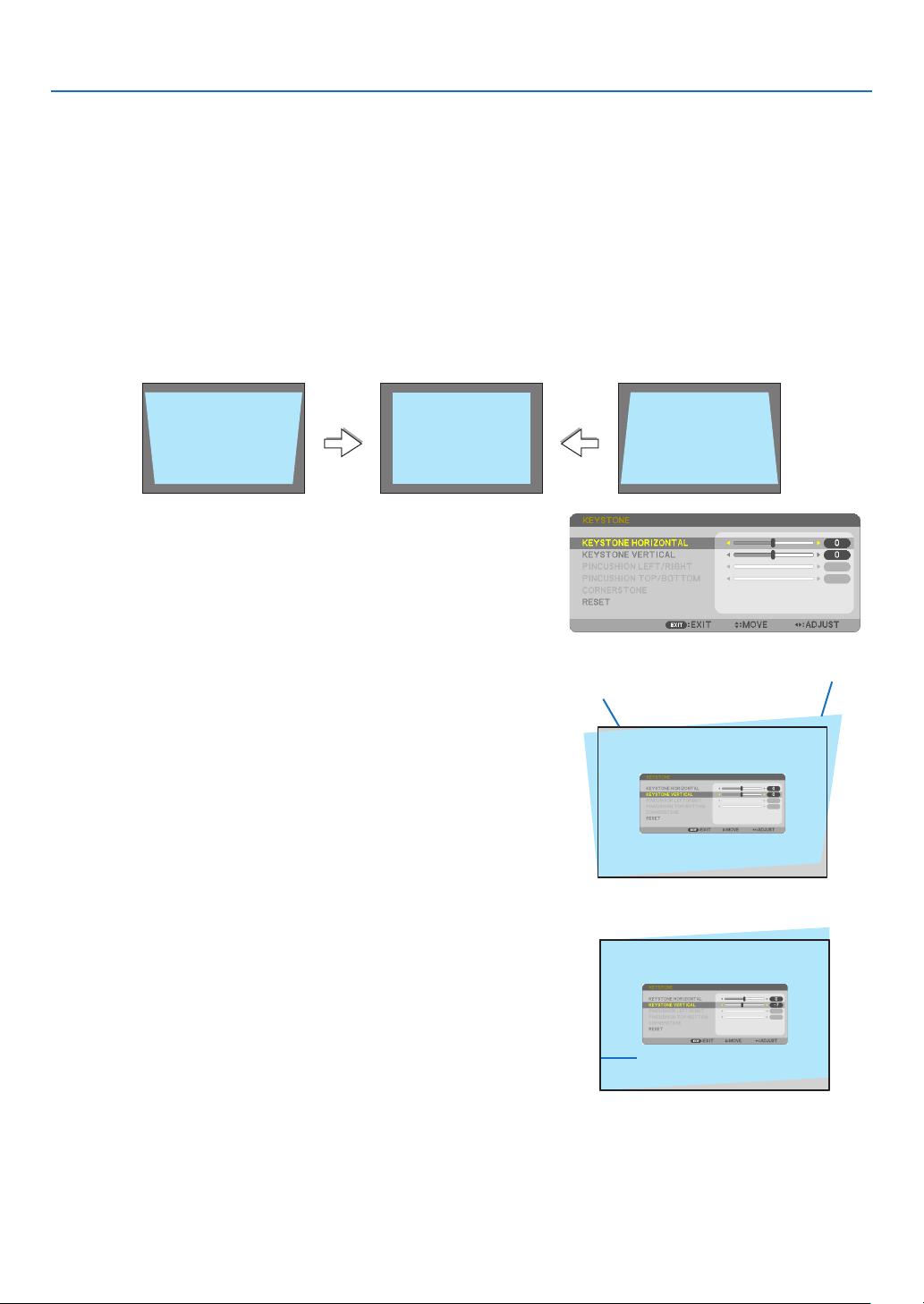
❻ Correcting Keystone Distortion [KEYSTONE]
When the projector and screen are not set correctly, keystone distortion occurs. For correcting this distortion, you
can use the “Keystone” function, a digital technology that can adjust for keystone-type distortion, resulting in a
crisp, square image.
The function of Automatic Keystone Correction is ON as the default factory setting.
The following procedure explains how to use the [KEYSTONE] screen from the menu to correct trapezoidal distor-
tions when the projector is placed diagonally to the screen.
•BeforeperformingKEYSTONEcorrection
The KEYSTONE correction has four features, KEYSTONE HORIZONTAL, KEYSTONE VERTICAL, PINCUSHION
LEFT/RIGHT, PINCUSHION TOP/BOTTOM, and CORNERSTONE. If the value of either CONERSTONE or PIN-
CUSHION has corrected, KEYSTONE HORIZONTAL and KEYSTONE VERTICAL are disabled. In this case, RESET
the corrected values and restart to correct distortion.
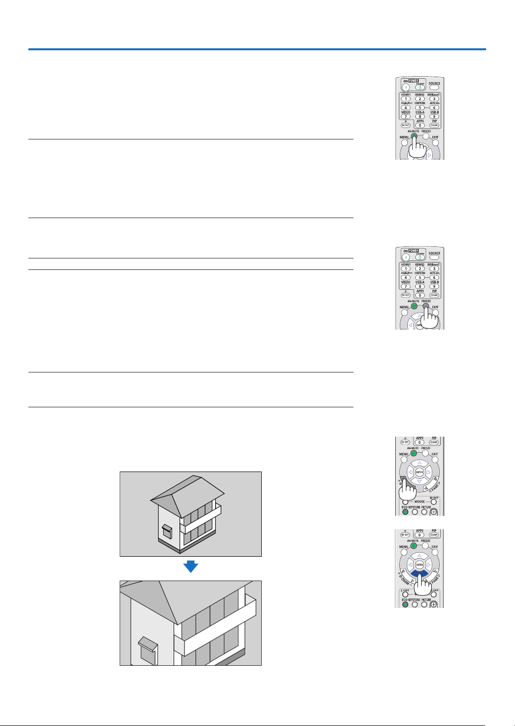
1. Press the ▼buttonontheprojectorcabinet.
The Keystone screen will be displayed on the screen.
•PresstheKEYSTONEbuttonwhenusingtheremotecontrol.
•SeepageforPINCUSHION.
•SeepageforCORNERSTONE.
•SeepageforRESET.
2. Press the ▼buttontoselect[KEYSTONEVERTICAL]andthen
use the ◀ or ▶sothattheleftandrightsidesoftheprojected
image are parallel.
*Adjusttheverticalkeystonedistortion.
Projected area
Screenframe
3. Align the left (or right) side of the screen with the left (or right)
sideoftheprojectedimage.
•Usetheshortersideoftheprojectedimageasthebase.
•Intherightexample,usetheleftsideasthebase.
Alignleftside
19
2. Projecting an Image (Basic Operation)
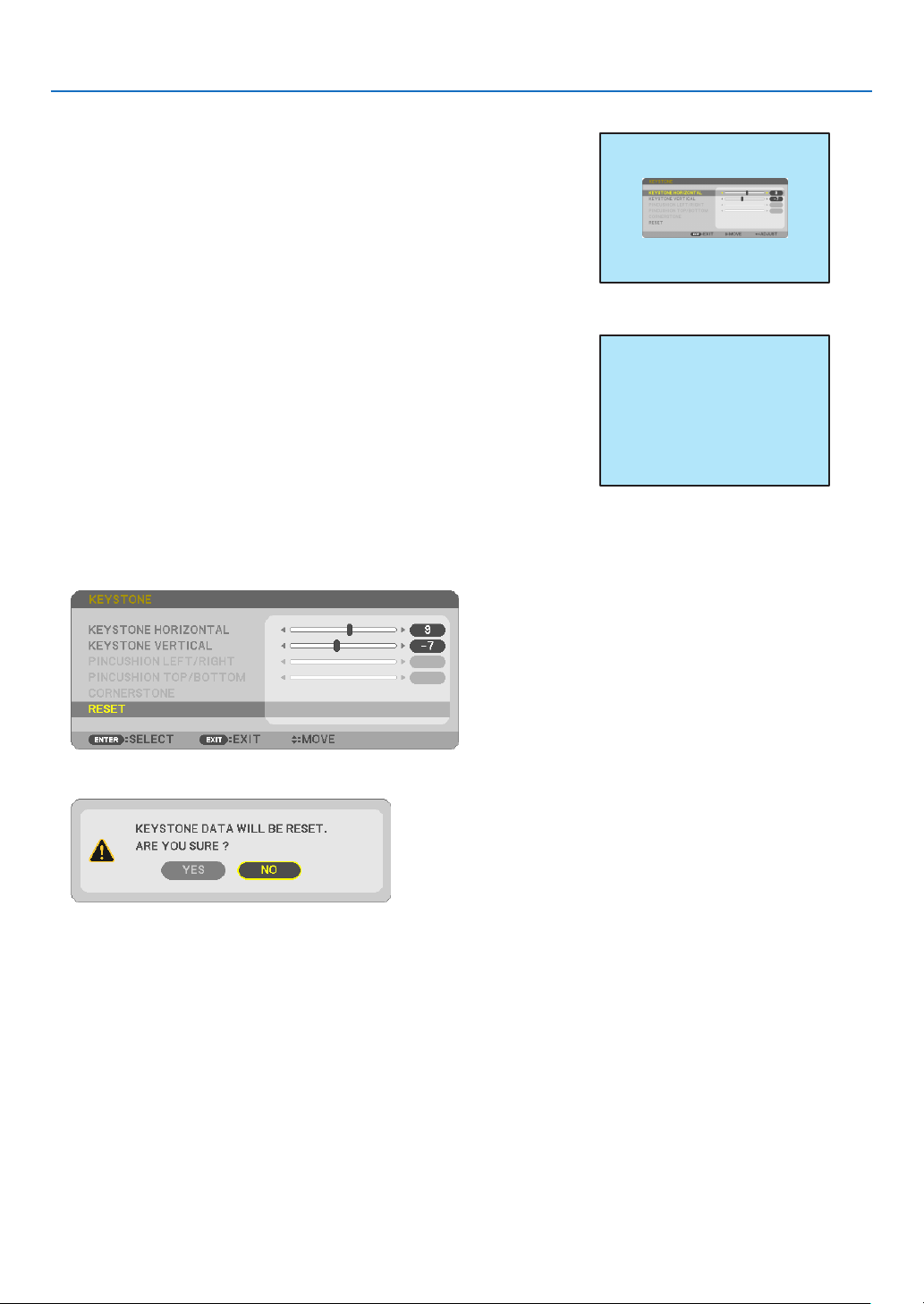
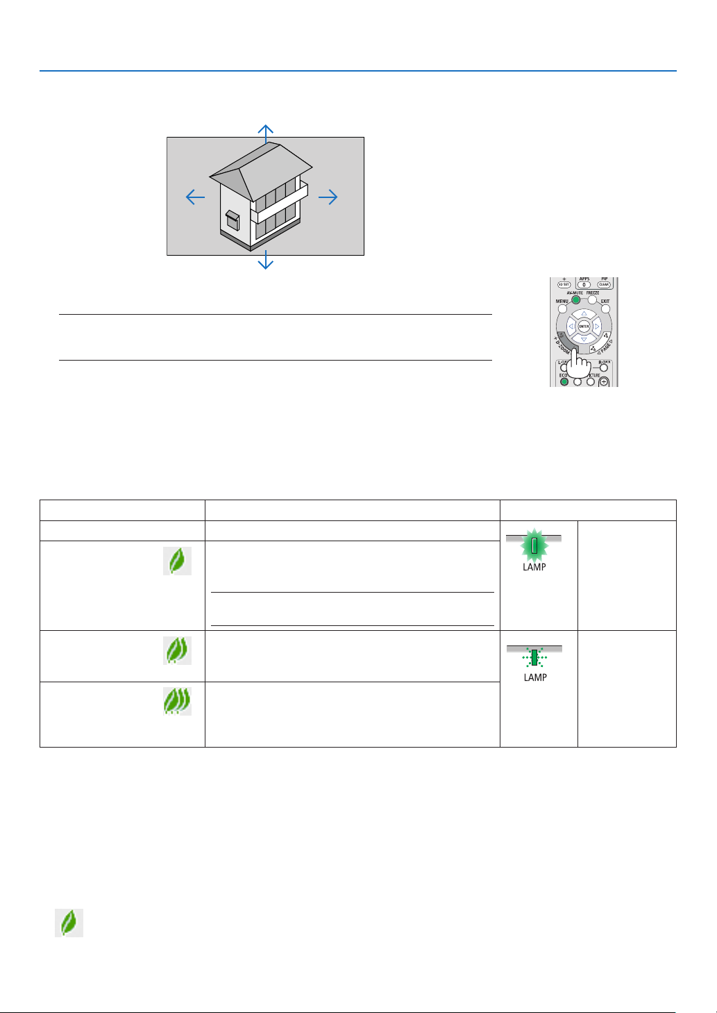
4. Press the ▲buttontoselect[KEYSTONEHORIZONTAL]andthen
use the ◀ or ▶sothatthetopandbottomsidesoftheprojected
image are parallel.
•Adjustthehorizontalkeystonedistortion.
5. Repeat steps 2 and 4 to correct keystone distortion.
6.AftercompletingKeystonecorrection,presstheEXITbutton.
The Keystone screen will disappear.
•ToperformKeystonecorrectionagain,pressthe▼ button to display
the Keystone screen and repeat above steps 1 to 6.
To return the keystone adjustments to default:
1. Press the ▼buttontoselect[RESET]andpresstheENTERbutton.
2. Press the ◀ or ▶buttontoselect[YES]andpresstheENTERbutton.
The adjustments will be reset.
Alltheadjustmentsforalltheveitemswillberesetatthesametime.
•TheKEYSTONEfeaturecancauseanimagetobeslightlyblurredbecausethecorrectionismadeelectronically.
20
2. Projecting an Image (Basic Operation)
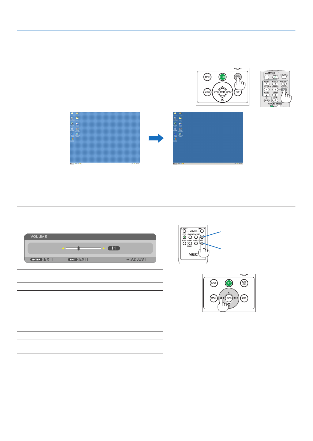
❼ Optimizing Computer Signal Automatically
Adjusting the Image Using Auto Adjust
Optimizing a computer image automatically. (COMPUTER)
Press the AUTO ADJ. button to optimize a computer image automatically.
This adjustment may be necessary when you connect your computer
for the first time.
[Poorpicture][Adjustedpicture]
NOTE:
Somesignalsmaytaketimetodisplayormaynotbedisplayedcorrectly.
•IftheAutoAdjustoperationcannotoptimizethecomputersignal,trytoadjust[HORIZONTAL],[VERTICAL],[CLOCK],and[PHASE]manually.
(→page
58,59)
❽ Turning Up or Down Volume
Sound level from the speaker or audio output can be adjusted.
TIP:Whennomenusappear,the◀ and ▶buttonsontheprojectorcabinet
workasavolumecontrol.
NOTE:
•Volumecontrolisnotavailablewiththe◀ or ▶buttonwhenanimage
ismagniedbyusingtheD-ZOOM(+)buttonorwhenthemenuis
displayed.
•Volumecontrolisnotavailablewiththe◀ or ▶buttonwhenVIEWER
is used.
TIP:The[BEEP]soundvolumecannotbeadjusted.Toturnoffthe[BEEP]
sound,fromthemenu,select[SETUP]→[OPTIONS(1)]→[BEEP]→[OFF].
Increasevolume
Decrease volume
21
2. Projecting an Image (Basic Operation)
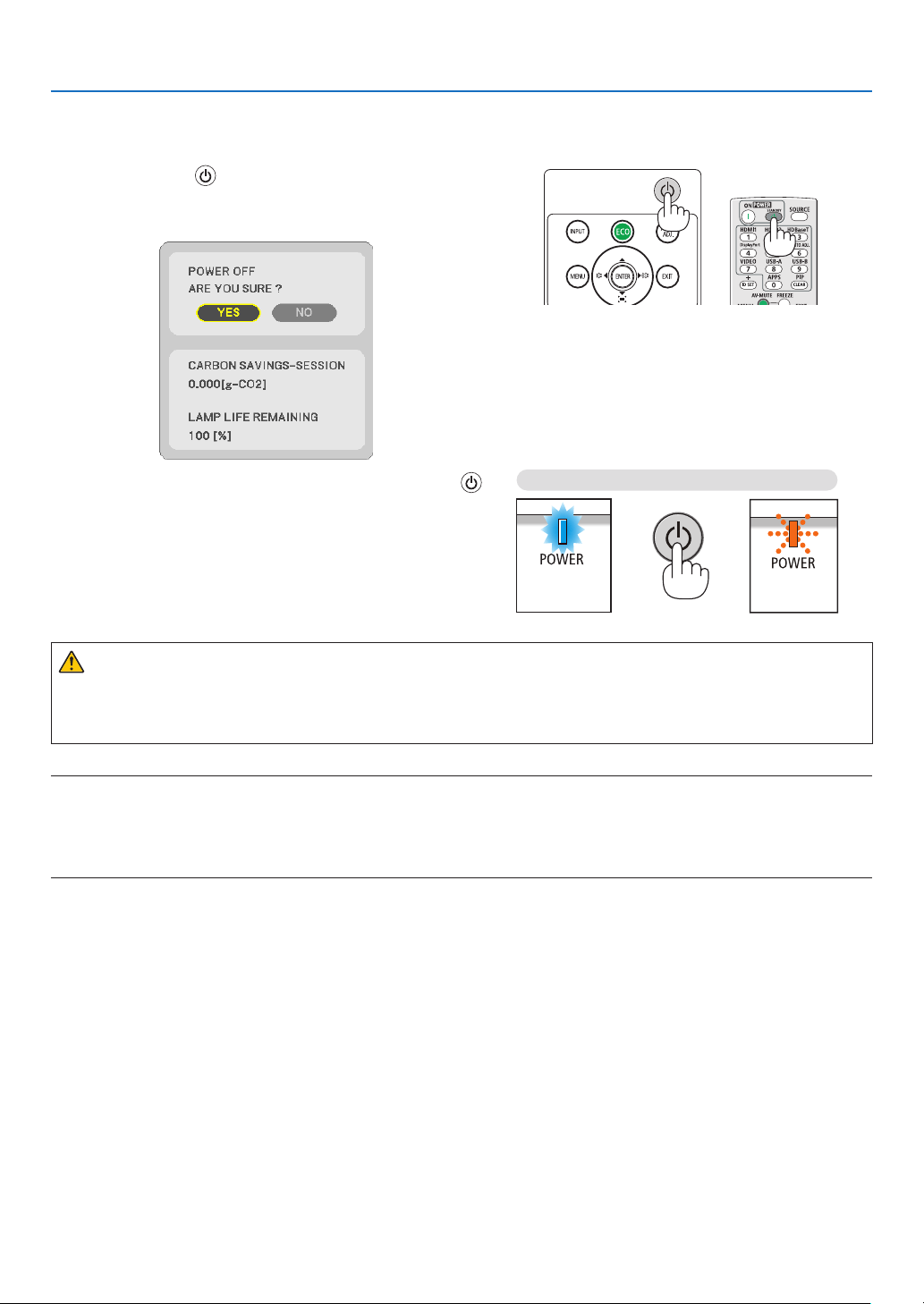
❾ Turning off the Projector
Toturnofftheprojector:
1. First, press the
(POWER)buttonontheprojector
cabinetortheSTANDBYbuttonontheremotecontrol.
The confirmation message will be displayed.
2.Secondly,presstheENTERbuttonorpressthe
(POWER)ortheSTANDBYbuttonagain.
Thelampwillturnoffandtheprojectorwillgointostandby
mode. When in standby mode, the POWER indicator will
blinkingorangeandtheSTATUSindicatorwillturnoffwhen
[NORMAL]isselectedfor[STANDBYMODE].
Power On
Steady blue light
Standby
Blinking orange
light
CAUTION:
Parts of the projector may become temporarily heated if the projector is turned off with the POWER button or if
the AC power supply is disconnected during normal projector operation.
Use caution when picking up the projector.
NOTE:
•Whilethepowerindicatorisblinkingblueinshortcycles,thepowercannotbeturnedoff.
•Youcannotturnoffthepowerfor60secondsimmediatelyafterturningitonanddisplayinganimage.
•DonotdisconnecttheACpowersupplytotheprojectorwithin10secondsaftermakingadjustmentorsettingchangesandclosingthe
menu.Doingsocancauselossofadjustmentsandsettings.

22
2. Projecting an Image (Basic Operation)
❿ When Moving the Projector
Preparation:Makesurethattheprojectoristurnedoff.
1. Put on the lens cap.
2. Unplug the power cord.
3. Disconnect any other cables.
•RemovetheUSBmemoryorthewirelessLANUnitifitisinsertedintotheprojector.
(→ page
41, 95)
23
❶ Turning off the Image and Sound
Press the AV-MUTE button to turn off the image and sound for a short period of
time. Press again to restore the image and sound.
The projector’s power-saving function will work 10 seconds after the image is
turned off.
As a result, the lamp power will be reduced.
NOTE:
•Eventhoughtheimageisturnedoff,themenustillremainsonthescreen.
•SoundfromtheAUDIOOUTjack(Stereomini)canbeturnedoff.
•Evenwhenthepower-savingfunctionworks,thelamppowermayberestoredtoitsoriginallevel
temporarily.
•Torestoretheimage,evenifyoupresstheAV-MUTEbuttonimmediatelyafterthestartofthe
power-savingfunction,thelampbrightnessmaynotberestoredtoitsoriginallevel.
❷ Freezing a Picture
Press the FREEZE button to freeze a picture. Press again to resume motion.
NOTE:Theimageisfrozenbuttheoriginalvideoisstillplayingback.
•ThisfeaturecannotbeusedwhenUSB-Aisselectedastheinputterminal.
❸ Magnifying a Picture
You can enlarge the picture up to four times.
NOTE:
•Themaximummagnicationmaybelessthanfourtimesdependingonthesignal.
•ThisfeaturecannotbeusedwhenLAN,andUSB-Bisselectedastheinputterminal.
To do so:
1.PresstheD-ZOOM(+)buttontomagnifythepicture.
To move the magnified image, use the ▲,▼,◀ or ▶ button.
3. Convenient Features
24
3. Convenient Features
2. Press the ▲▼◀▶ button.
Theareaofthemagniedimagewillbemoved.
3.PresstheD-ZOOM(−)button.
Each time the D-ZOOM (−) button is pressed, the image is reduced.
NOTE:
•Theimagewillbemagniedordemagniedatthecenterofthescreen.
•Displayingthemenuwillcancelthecurrentmagnication.
❹ Changing Eco Mode/Checking Energy-Saving Effect
Using Eco Mode [ECO MODE]
The ECO MODE (NORMAL and ECO) increases lamp life, while lowering power consumption and cutting down on
CO
2
emissions.
Four brightness modes of the lamp can be selected: [OFF], [AUTO ECO], [NORMAL] and [ECO] modes.
[ECO MODE] Description Status of LAMP indicator
[OFF] The lamp brightness is 100%.
Steady Green
light
[AUTO ECO]
Lamp power consumption will be changed between
[OFF] and [NORMAL] automatically according to
picture level
NOTE:Abrightgradationmaybelessvisibledependingon
theimage.
[NORMAL]
Lamp power consumption: approx. 80% brightness
(MC372X: 86%). The lamp life will extend by lowering
the lamp power.
Blinking Green
light
[ECO]
Lamp power consumption: approx. 67% brightness
(MC372X: 72%). The lamp life will extend longer than
the one on NORMAL mode by controlling power
appropriate for the lamp.
To turn on the [ECO MODE], do the following:
1.PresstheECOButtonontheremotecontroltodisplay[ECOMODE]screen.
2.PresstheECObuttonagaintoselectamodeyouwish.
•EachtimetheECObuttonispressed,thechoiceswillbechanged:
OFF → AUTO ECO → NORMAL → ECO → OFF
TIP:
•TheleafsymbolatthebottomofthemenushowsthecurrentselectionofECOmode.
25
3. Convenient Features
NOTE:
•The[ECOMODE]canbechangedbyusingthemenu.
Select[SETUP]→[GENERAL]→[ECOMODE].
•Thelampliferemainingandlamphoursusedcanbecheckedin[USAGETIME].Select[INFO.]→[USAGETIME].
•Theprojectorisalwaysin[NORMAL]for90secondsafterthelampisturnedonandwhilethePOWERindicatorisblinkingblue.Thelamp
conditionwillnotbeaffectedevenwhen[ECOMODE]ischanged.
•Afteralapseof1minutefromwhentheprojectordisplaysno-signalguidance,ablue,blackorlogoscreen,[ECOMODE]willautomatically
switchto[ECO].Theprojectorwillreturntoitsoriginalsettingonceasignalisaccepted.
•Iftheprojectorisoverheatedin[OFF]mode,theremaybeacasewherethe[ECOMODE]automaticallychangesto[NORMAL]modeto
protecttheprojector.Whentheprojectorisin[NORMAL]mode,thepicturebrightnessdecreases.Whentheprojectorcomesbacktonormal
temperature,the[ECOMODE]returnstoitsoriginalsetting.
Thermometersymbol[
]indicatesthe[ECOMODE]isautomaticallysetto[NORMAL]modebecausetheinternaltemperatureistoohigh.
•Immediatelyafter[ECOMODE]ischangedfrom[ECO]tooneof[OFF],[AUTOECO],or[NORMAL],thelampbrightnessmaydecrease
temporarily.Thisisnotamalfunction.
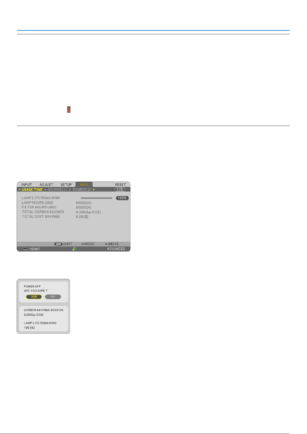
Checking Energy-Saving Effect [CARBON METER]
This feature will show energy-saving effect in terms of CO
2
emission reduction (kg) when the projector’s [ECO MODE]
is set to [AUTO ECO], [NORMAL], or [ECO]. This feature is called as [CARBON METER].
There are two messages: [TOTAL CARBON SAVINGS] and [CARBON SAVINGS-SESSION]. The [TOTAL CARBON
SAVINGS] message shows the total amount of CO
2
emission reduction from the time of shipment up to now. You
can check the information on [USAGE TIME] from [INFO.] of the menu. (→ page
74)
The [CARBON SAVINGS-SESSION] message shows the amount of CO
2
emission reduction between the time of
changing to ECO MODE immediately after the time of power-on and the time of power-off. The [CARBON SAVINGS-
SESSION] message will be displayed in the [POWER OFF/ ARE YOU SURE?] message at the time of power-off.
TIP:
•TheformulaasshownbelowisusedtocalculatetheamountofCO
2
emission reduction.
AmountofCO
2
emissionreduction=(PowerconsumptioninOFFforECOMODE−PowerconsumptioninAUTOECO/NORMAL/ECOfor
ECOMODE)×CO
2
conversionfactor.*WhentheimageisturnedoffwiththeAV-MUTEbutton,theamountofCO
2
emmission reduction
willalsoincrease.
*CalculationforamountofCO
2
emissionreductionisbasedonanOECDpublication“CO
2
EmissionsfromFuelCombustion,2008Edition”.
•The[TOTALCARBONSAVINGS]iscalculatedbasedonsavingsrecordedin15minutesintervals.
•Thisformulawillnotapplytothepowerconsumptionwhichisnotaffectedbywhether[ECOMODE]isturnedonoroff.
26
3. Convenient Features
❺ Using 4-Point Corner to Correct Keystone Distortion
[CORNERSTONE]
Use the [CORNERSTONE] and [PINCUSHION] features to correct keystone (trapezoidal) distortion to make the top
or bottom and the left or right side of the screen longer or shorter so that the projected image is rectangular.
Beforeperformingcorrection
The KEYSTONE correction has features, KEYSTONE (HORIZONTAL/VERTICAL), PINCUSHION (LEFT/RIGHT, TOP/
BOTTOM), and CORNERSTONE. If the value of either CONERSTONE or PINCUSHION has corrected, KEYSTONE
HORIZONTAL and KEYSTONE VERTICAL are disabled. In this case, RESET the corrected values and restart to
correct distortion.
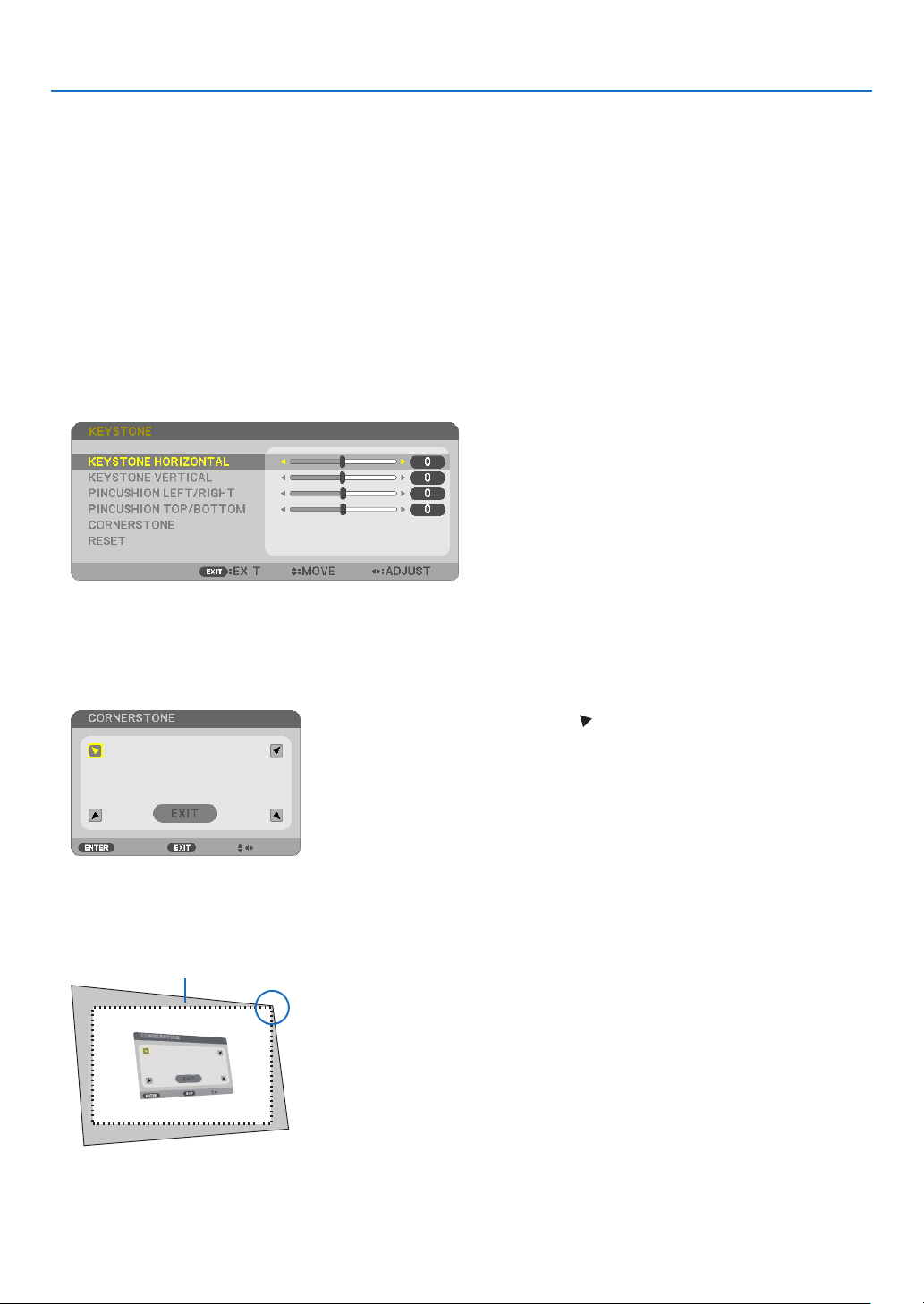
Cornerstone
1.PresstheKEYSTONEbuttonwithnomenudisplayed.
The KEYSTONE screen will be displayed.
•PresstheKEYSTONEbuttonwhenusingtheremotecontrol.
•SeepageforPINCUSHION.
2. Press the ▼buttontoselect[CORNERSTONE]andpresstheENTERbutton.
Thedrawingshowstheupperlefticon() is selected.
The CORNERSTONE screen will be displayed.
3.Projectanimagesothatthescreenissmallerthantheareaoftheraster.
4. Pick up any one of the corners and align the corner of the image with a corner of the screen.
Projected image
The drawing shows the upper right corner.
TIP:IfeitherCORNERSTONEorPINCUSIONisadjusted,theoptionsKEYSTONEVERTICALandKEYSTONEHORIZONTALbecomeunavailable.
Inthiscase,RESETthecorrectedvaluesandrestarttocorrectdistortion.
27
3. Convenient Features
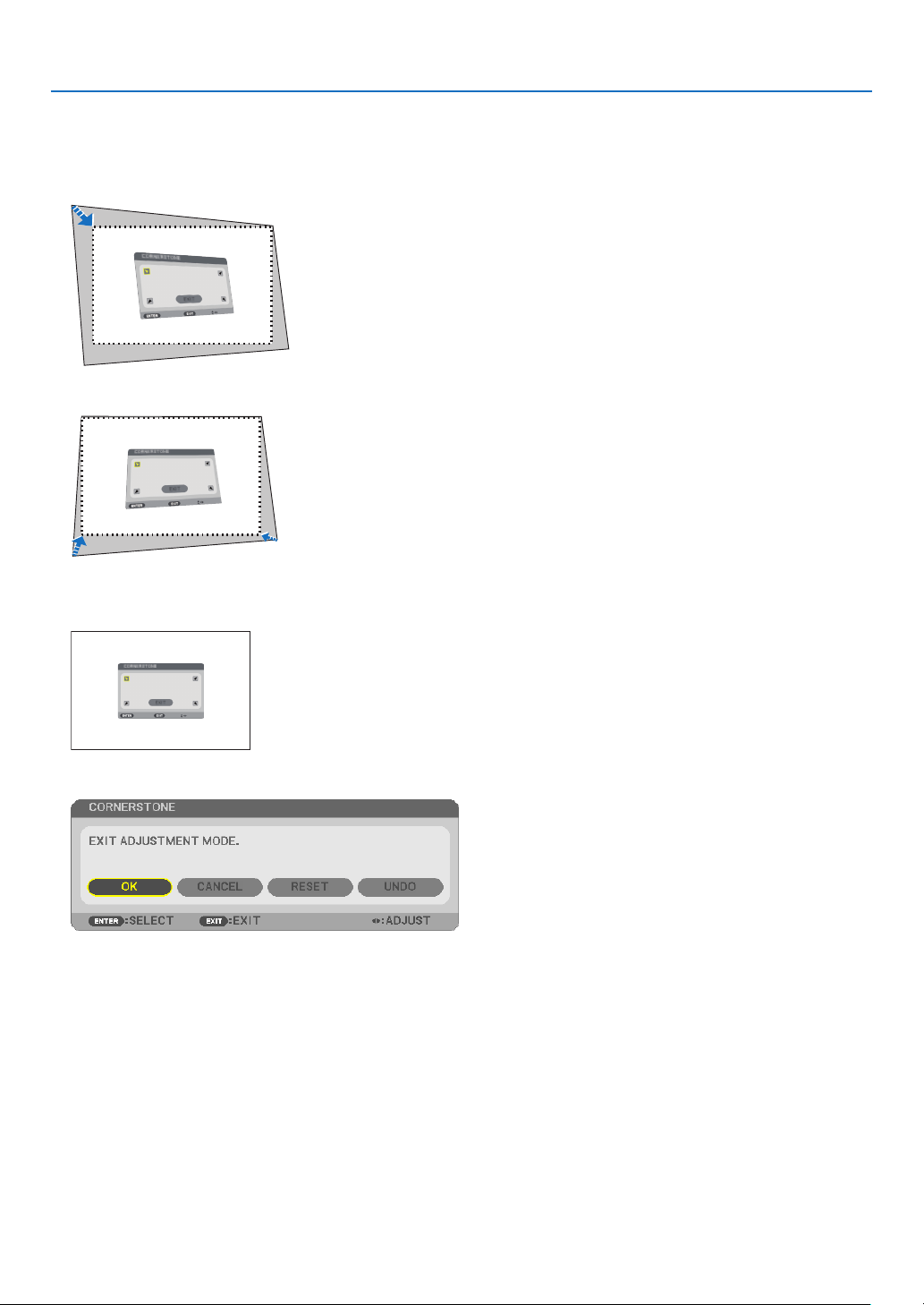
5. Use the ▲▼◀▶ button to select one icon (▲)whichpointsinthedirectionyouwishtomovetheprojected
image frame.
6.PresstheENTERbutton.
7. Use the ▲▼◀▶buttontomovetheprojectedimageframeasshownontheexample.
8.PresstheENTERbutton.
9. Use the ▲▼◀▶ button to select another icon which points in the direction.
OntheCornerstoneadjustmentscreen,select[EXIT]orpresstheEXITbuttonontheremotecontrol.
The confirmation screen is displayed.
10
. Press the ◀ or ▶buttontohighlightthe[OK]andpresstheENTERbutton.
This completes the Cornerstone correction.
Selecting [CANCEL] will return to the adjustment screen without saving changes (Step 3).
Selecting [RESET] will return to the factory default.
Selecting [UNDO] will exit without saving changes.
28
3. Convenient Features
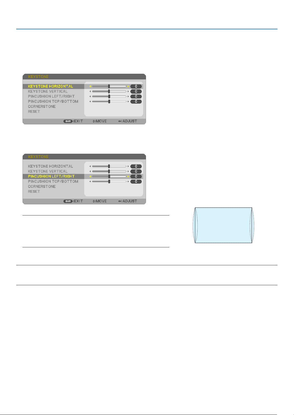
Pincushion
By this feature, it enables to adjust left and right side or top and bottom side independently for reforming pincushion
distortion.
1.PresstheKEYSTONEbuttonwithnomenudisplayed.
The KEYSTONE screen will be displayed.
•PresstheKEYSTONEbuttonwhenusingtheremotecontrol.
2. Press the ▼ or ▲buttontoselect[PINCUSHIONLEFT/RIGHT]
or[PINCUSHIONTOP/BOTTOM].
3. Press the ◀ or ▶ button to correct distortion.
NOTE:
•The[PINCUSHIONLEFT/RIGHT]or[PINCUSHIONTOP/BOTTOM]itemisnot
availablewhen[KEYSTONEHORIZONTAL],[KEYSTONEVERTICAL]or[COR-
NERSTONE]isactivated.
•Beforeperformingcorrection,setthelensshifttothecenterposition.
4.PresstheEXITwhenPINCUSHIONadjustmentiscompleted.
NOTE:
•Evenwhentheprojectoristurnedon,thelastusedcorrectionvaluesareapplied.
•[PINCUSHION]and[CORNERSTONE]correctionscancausetheimagetobeslightlyblurredbecausethecorrectionismadeelectronically.
29
3. Convenient Features
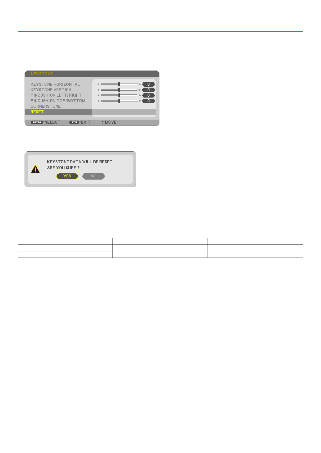
Resetthekeystoneandpincushionadjustmenttothedefaultvalue
1.PresstheKEYSTONEbuttonwithnomenudisplayed.
On the displayed KEYSTONE menu, set the cursor at RESET using the ▼ button and press ENTER button.
•Conrmationmessageisdisplayedon.
2.MovethecursorontoYESusingeither◀ or ▶buttonandthenpresstheENTER.
NOTE:
•AlladjustedvaluessetintheKEYSTONEadjustmentareresettoinitialvalues.
TIP:
AdjustablerangeoftheKEYSTONEandtheCORNERSTONE:
HorizontalDirectionVerticalDirection
CORNERSTONE
Approx.±30°(Max)Approx.±30°(Max)
KEYSTONE
Adjustablerangemaybenarrowerdependingoninputsignal.
30
3. Convenient Features
❻
Preventing the Unauthorized Use of the Projector [SECURITY]
A keyword can be set for your projector using the Menu to avoid operation by an unauthorized user. When a key-
word is set, turning on the projector will display the Keyword input screen. Unless the correct keyword is entered,
the projector cannot project an image.
•The[SECURITY]settingcannotbecancelledbyusingthe[RESET]ofthemenu.
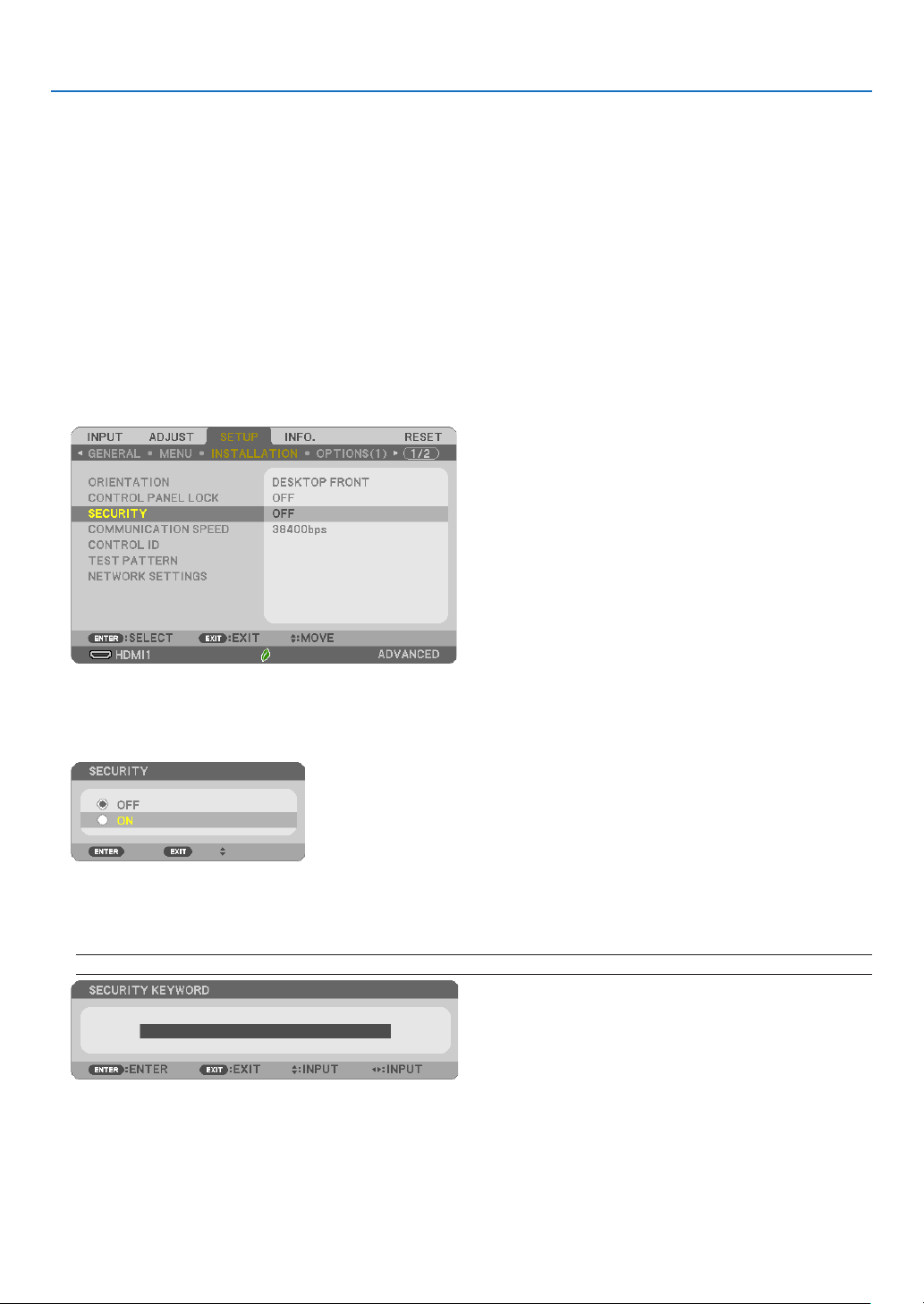
ToenabletheSecurityfunction:
1.PresstheMENUbutton.
The menu will be displayed.
2. Press the ▶buttontwicetoselect[SETUP]andpressthe▼buttonortheENTERbuttontoselect[GEN-
ERAL].
3. Press the ▶buttontoselect[INSTALLATION].
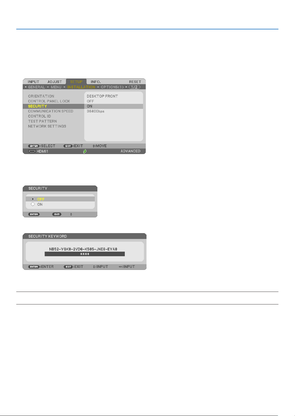
4. Press the ▼buttonthreetimestoselect[SECURITY]andpresstheENTERbutton.
TheOFF/ONmenuwillbedisplayed.
5. Press the ▼buttontoselect[ON]andpresstheENTERbutton.
The[SECURITYKEYWORD]screenwillbedisplayed.
6.Typeinacombinationofthefour▲▼◀▶buttonsandpresstheENTERbutton.
NOTE:Akeywordmustbe4to10digitsinlength.
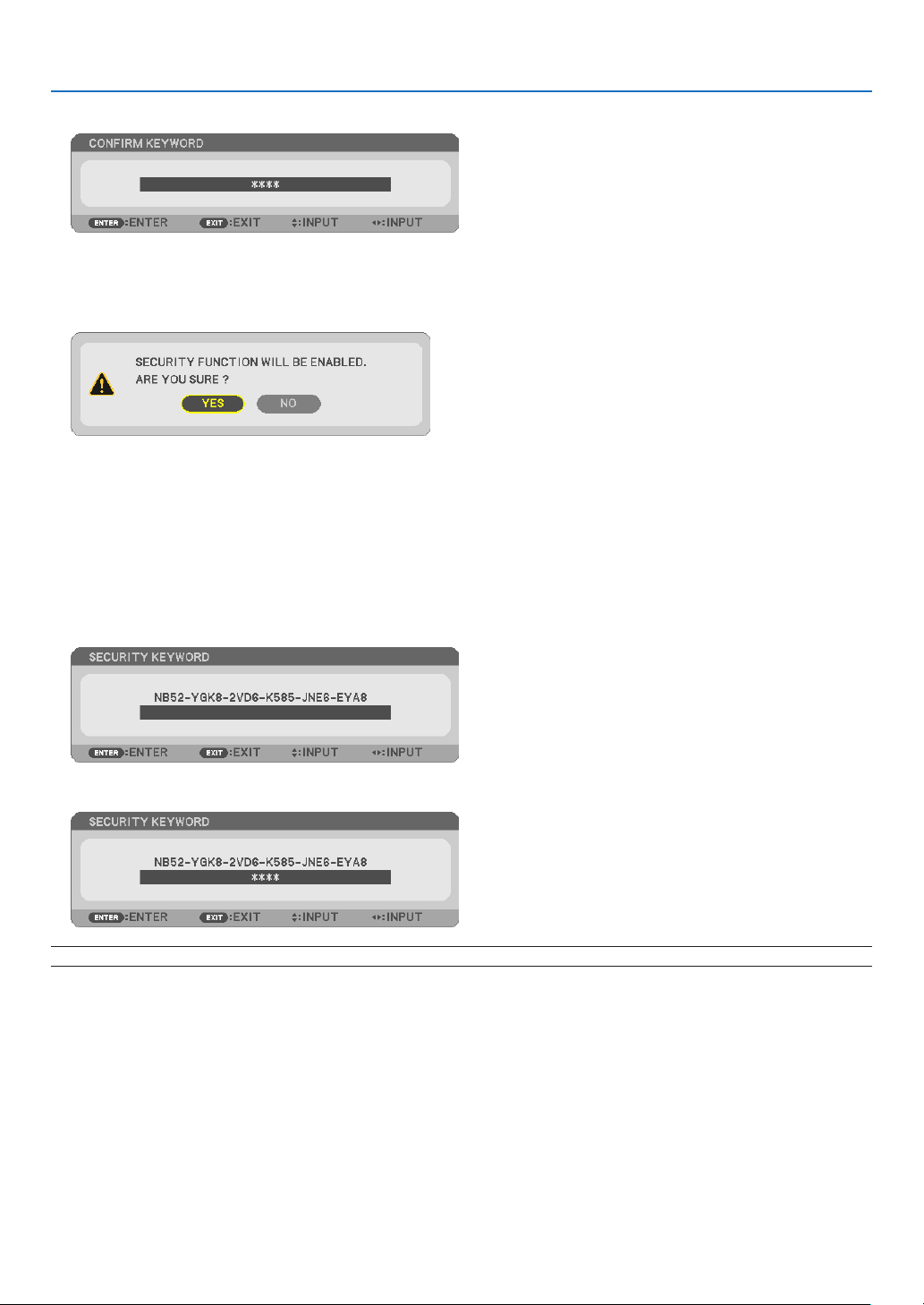
The[CONFIRMKEYWORD]screenwillbedisplayed.
31
3. Convenient Features
7.Typeinthesamecombinationof▲▼◀▶buttonsandpresstheENTERbutton.
The confirmation screen will be displayed.
8.Select[YES]andpresstheENTERbutton.
TheSECURITYfunctionhasbeenenabled.
Toturnontheprojectorwhen[SECURITY]isenabled:
1.PressthePOWERbutton.
Theprojectorwillbeturnedonanddisplayamessagetotheeffectthattheprojectorislocked.
2.PresstheMENUbutton.
3.TypeinthecorrectkeywordandpresstheENTERbutton.Theprojectorwilldisplayanimage.
NOTE:Thesecuritydisablemodeismaintaineduntilthemainpoweristurnedofforunpluggingthepowercord.
32
3. Convenient Features
TodisabletheSECURITYfunction:
1.PresstheMENUbutton.
The menu will be displayed.
2.Select[SETUP]→[INSTALLATION]→[SECURITY]andpresstheENTERbutton.
TheOFF/ONmenuwillbedisplayed.
3.Select[OFF]andpresstheENTERbutton.
TheSECURITYKEYWORDscreenwillbedisplayed.
4.TypeinyourkeywordandpresstheENTERbutton.
Whenthecorrectkeywordisentered,theSECURITYfunctionwillbedisabled.
NOTE:Ifyouforgetyourkeyword,contactyourdealer.Yourdealerwillprovideyouwithyourkeywordinexchangeforyourrequestcode.
YourrequestcodeisdisplayedintheKeywordConrmationscreen.Inthisexample[NB52-YGK8-2VD6-K585-JNE6-EYA8]isarequestcode.
33
3. Convenient Features
❼
Operating Your Computer’s Mouse Functions from the
Projector’s Remote Control via the USB Cable (Remote Mouse
Function)
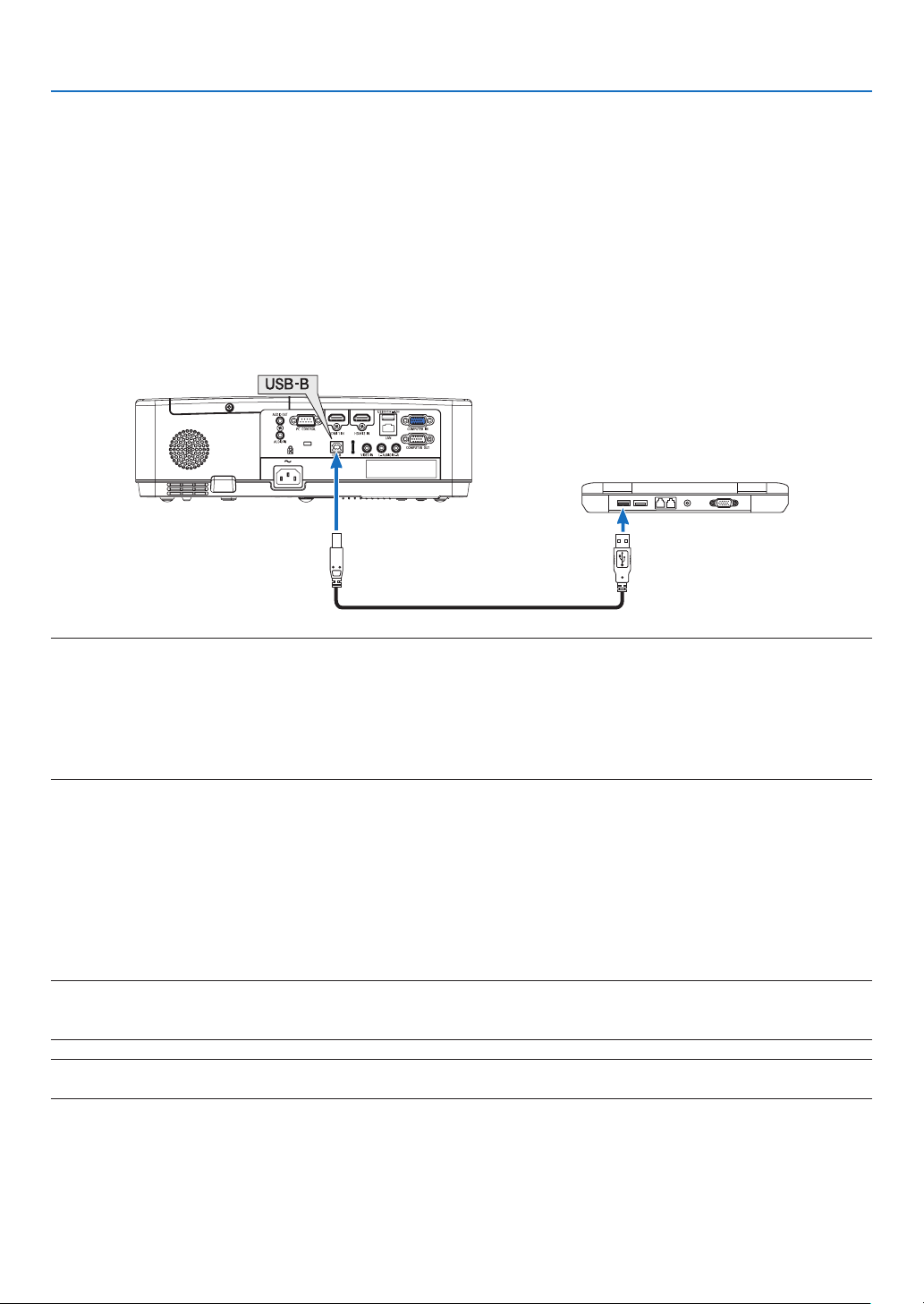
The built-in remote mouse function enables you to operate your computer’s mouse functions from the supplied
remote control when the projector is connected to a computer via a commercially available USB cable (compatible
with USB 2.0 specifications).
Press the USB-B button on the remote control, or select [USB-B] for the source on the On-screen menu.
•UsingtheUSBcabletoconnecttheprojectorandthecomputerwillalsostartUSBDisplayfunction.
•WhenyouconnectyourcomputerandtheprojectorbyaUSBcableforthersttime,yourcomputerwillreadin
the software. It will take few minutes for starting up the USB display.
USB cable (not supplied)
NOTE:
•AUSBcablemustsupporttheUSB2.0Specications.
•Themousefunctioncanbeusedwiththefollowingoperatingsystems:
Windows7,WindowsXP,WindowsVista
•Waitatleast5secondsafterdisconnectingtheUSBcablebeforereconnectingitandviceversa.ThecomputermaynotidentifytheUSB
cableifitisrepeatedlyconnectedanddisconnectedinrapidintervals.
•ConnecttheprojectortothecomputerwithaUSBcableafterstartingthecomputer.Failuretodosomayfailtostartthecomputer.
Operatingyourcomputer’smousefromtheremotecontrol
You can operate your computer’s mouse from the remote control.
PAGE ▽/△ Button ������������������������������ scrolls the viewing area of the window or to move to the previous or next slide in PowerPoint on
your computer�
▲▼◀▶ Buttons ������������������������������� moves the mouse cursor on your computer�
MOUSE L-CLICK/ENTER Button ����������� works as the mouse left button�
MOUSE R-CLICK Button ���������������������� works as the mouse right button�
NOTE:
•Whenyouoperatethecomputerusingthe▲▼◀ or ▶buttonwiththemenudisplayed,boththemenuandthemousepointerwillbe
affected.Closethemenuandperformthemouseoperation.
TIP:YoucanchangethePointerspeedontheMousePropertiesdialogboxontheWindows.Formoreinformation,seetheuserdocumenta-
tionoronlinehelpsuppliedwithyourcomputer.
34
3. Convenient Features
❽ Projecting Your Computer’s Screen Image from the
Projector via the USB Cable (USB Display)
Using a commercially available USB cable (compatible with USB 2.0 specifications) to connect the computer with the
projector allows you to send your computer screen image to the projector for displaying. Power On/Off and source
selection of the projector can be done from your computer without connecting a computer cable (VGA).
The USB Display utilizes the function of Image Express Utility Lite which is pre-installed software on the projector.
NOTE:
•TomaketheUSB-DisplayavailableonWindowsXP,theWindowsuseraccountmusthave“Administrator”privilege.
•USBDisplaywillnotworkin[NORMAL]of[STANDBYMODE].(→page
71)
1. Start the computer.
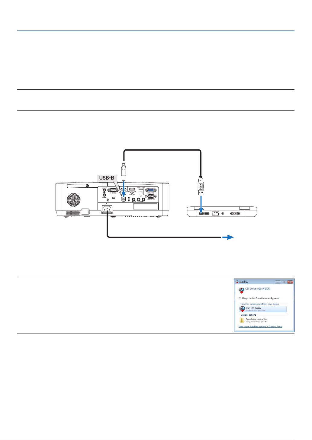
2.Connecttheprojector’spowercordtothewalloutletandputtheprojectorintostandbycondition.
3.UsetheUSBcabletoconnectthecomputerwiththeprojector.
USB cable (not supplied)
→ To wall outlet
Power cord (supplied)
Themessage“Theprojectorisinstandbymode.Connectit?”willbedisplayedonthecomputerscreen.
•ThecontrolwindowofImageExpressUtilityLitewillbedisplayedonthetopofthescreen.
NOTE:Dependingonthecomputersetting,the“AutoPlay”windowmaybedisplayedwhenthecomputer
detectstheconnectiontotheprojector.Ifthishappens,clickthe“StartUSBDisplay”window.
4.Click“Yes”.
Theprojectorwillturnonandthemessage“Theprojectorisgettingready.Pleasewait.”willbedisplayedonthe
computerscreen.Thismessagewilldisappearinafewseconds.
35
3. Convenient Features
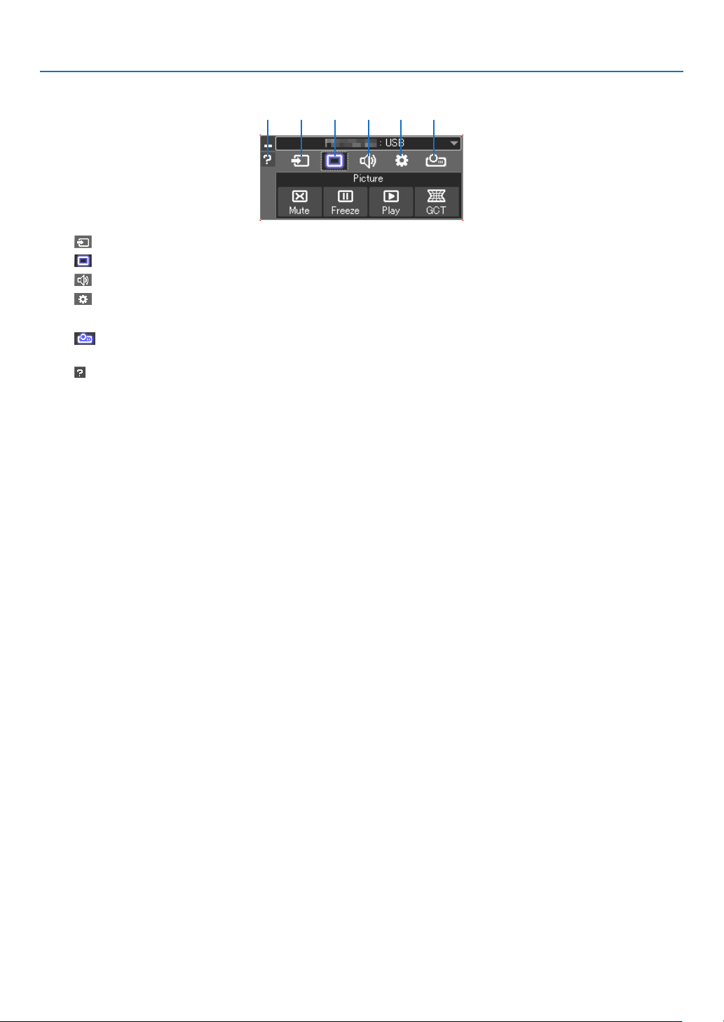
5.Operatethecontrolwindow.
(1) (Source) ��������Selects an input source of the projector�
(2)
(Picture) ��������Turns on or off AV-MUTE (Picture mute), and turns on or off FREEZE (Freeze a picture)�
(3)
(Sound) ���������Turns on or off AV-MUTE (Sound mute), play the sound and turns up or down the volume�
(4)
(Others) ��������Uses “Update”, “HTTP Server”*, “Settings” and “Information”�
* The HTTP Server cannot be selected when a USB cable is connected�
(5)
(Projection) �� Enables to change screen size for presentation, menu indication (hide/indicate), interruption prohibition/ accept
interruption�
(6)
(Help) ��������������Displays the help of Image Express Utility Lite�
(1) (2) (3) (4) (5)(6)
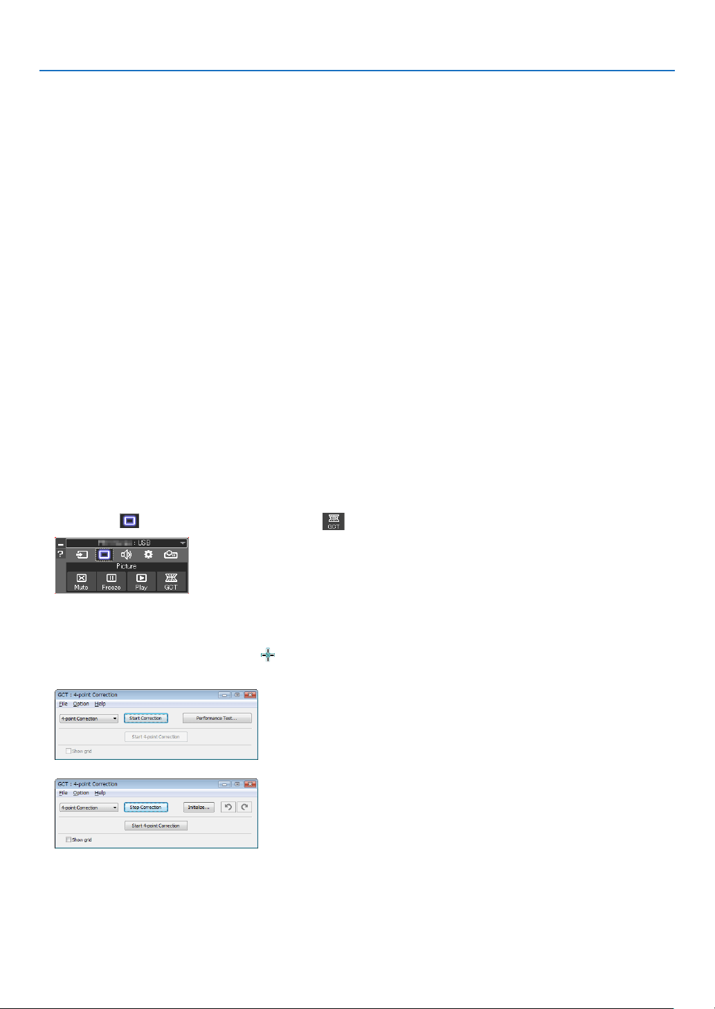
36
3. Convenient Features
9 Projecting an Image from an Angle (Geometric Correction
Tool in Image Express Utility Lite)
The Geometric Correction Tool (GCT) that is a function of the pre-installed software on the projector “Image Express
Utility Lite” allows you to correct distortion of images projected even from an angle.
What you can do with GCT
•TheGCTfeatureincludesthefollowingthreefunctions
•4-pointCorrection: You can fit a projected image within the border of the screen easily by align the four
corners of an image to the ones of the screen.
•Multi-pointCorrection: You can correct a distorted image on the corner of a wall or irregular shaped screen
by using many separated screens to correct the image as well as 4-point Correction.
•ParametersCorrection: You can correct a distorted image by using a combination of transformational rules
prepared in advance.
This section will show an example for use with 4-point Correction.
For information about “Multi-point Correction” and “Parameters Correction”, see the help file of Image Express
Utility Lite.
•Yourcorrectiondatacanbestoredintheprojectororyourcomputerwhichcanberestoredwhennecessary.
Projecting an Image from an Angle (GCT)
Preparation:
(1) Connect the projector to a computer by a USB cable. (→ page
34, USB Display)
(2) Adjust the projector position or the zoom so that the projected image can cover the whole screen area.
1.Clickthe“
”(Picture)iconandthenthe“”button.
The“4-pointCorrection”windowwillbedisplayed.
2.Clickthe“StartCorrection”buttonandthen“Start4-pointCorrection”button.
Agreenframeandamousepointer(
)willbedisplayed.
•Four[
•]markswillbeappearedatfourcorners.
3.Usethemousetoclickthe[•]markofwhichcorneryouwishtomove.
Thecurrentlyselected[•]markwillturnred.
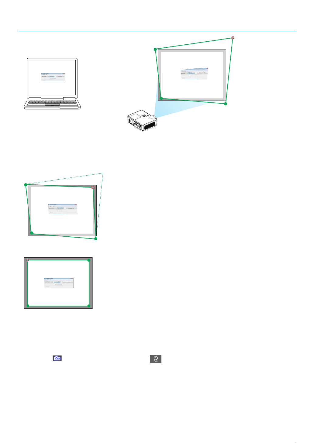
37
3. Convenient Features
(Intheaboveexample,Windowsscreensareomittedforclarication.)
4.Dragtheselected[
•]marktothepointyouwishtocorrectanddropit.
•Whenyouclicksomewherewithintheprojectimagearea,thenearestcornerwillgotothepositionwherethe
mouse cursor is.
5.RepeatStep3and4tocorrectthedistortionoftheprojectedimage.
6. After completing, right-click the mouse.
Thegreenframeandthemousepointerwilldisappearfromtheprojectedimagearea.Thiswillcompletethecor-
rection.
7.Clickthe“X”(close)buttononthe“4-pointCorrection”window.
The“4-pointCorrection”windowwilldisappearandthe4-pointcorrectionwilltakeeffect.
8.Clickthe“
”(Projection)iconandthenthe“”(Exit)button.
9.Click“Yes”.
TIP:
•Afterperformingthe4-pointcorrection,youcansavethe4-pointcorrectiondatatotheprojectorbyclicking“File”→“Exporttothe
projector…”onthe“4-pointCorrection”window.
•SeetheHelpofImageExpressUtilityLiteforoperating“4-pointCorrection”windowandotherfunctionsthanGCT.
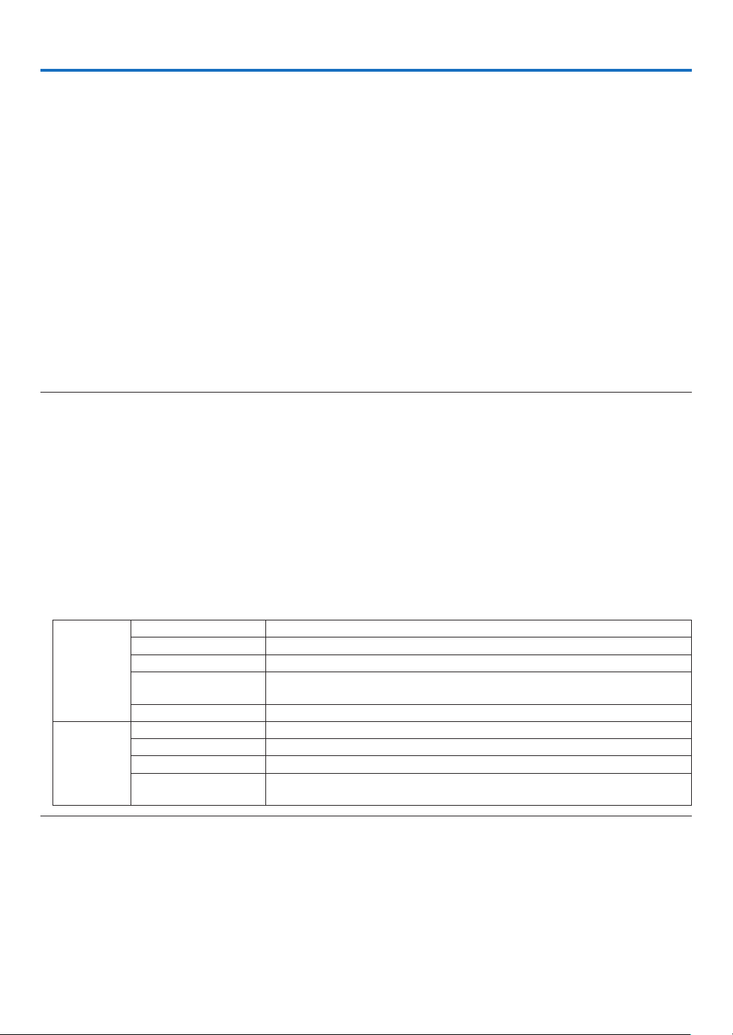
38
4. Using the VIEWER
❶ Things you can do with the VIEWER
The VIEWER has the following features.
•WhenyouinsertacommerciallyavailableUSBmemorycontainingthepictureintotheUSBport(TypeA)ofthe
projector, the images on the USB can be projected by the projector. By doing this, you can make a presentation
without using a personal computer.
•ThetypesofimagesthatcanbeprojectedintheVIEWERareJPEGandPNG.
•ThumbnailscanbedisplayedintheVIEWER,allowingyoutoquicklyselectapicturetobeprojected.
•Whenprojectingmultiplepicturescontinuously(SLIDESHOW),thepicturesmaybeswitchedmanually(manual
playback) or automatically (AUTO PLAY). The interval for changing the pictures can also be modified during AUTO
PLAY.
•Theprojectionordercanbespeciedbythepicturelename,letype,dateandsize,andtheascending/
descending order can be selected.
•Theorientationofthepicturecanberotatedinunitsof90°.
•Youcanchangethescreenoftheinputterminalinasignal-lessstate(backgroundlogo)orthebackgroundimage
of the MultiPresenter start-up screen (MultiPresenter logo). You can also set a password to prohibit third parties
from changing the pictures.
NOTE:
•WhentheVIEWER(slidescreen,lelistscreen)isbeingdisplayed,keystonecorrectionusingthe▼ / ▲buttonsisnotpossible.
ToperformkeystonecorrectionwhentheVIEWERisbeingdisplayed,presstheMENUbutton2timestodisplaytheon-screenmenu.
•WhentheVIEWERisbeingdisplayed,theFREEZEbuttonontheremotecontroldoesnotwork.
•Whenyouselect[RESET]→[ALLDATA]intheon-screenmenu,theoptionmenusettingsoftheVIEWERreturntothedefaultstatewhen
shippedfromthefactory.
•AboutUSBmemory
FormattheUSBmemoryusedbytheVIEWERoftheprojectorintheFAT32formatorFAT16format.
-TheprojectorcannotrecognizeaUSBmemorythathasbeenformattedintheNTFSformat.
-CheckthelesystemformatiftheUSBmemoryinsertedintotheprojectorisnotrecognized.
-RefertotheinstructionmanualorthehelpleoftheWindowsyouareusingfordetailsonhowtoformataUSBmemory.
-TheUSBportoftheprojectordoesnotguaranteethatallUSBmemoriescommerciallyavailablewillwork.
•Aboutcompatibleimages
-ThefollowingpicturescanbeprojectedbytheVIEWER.
JPEG Extension jpg, jpe, jpeg (case insensitive)
Format Baseline, progressive
Color RGB, grayscale
Resolution Baseline: Maximum 10000 × 10000 (pixel)
Progressive: Maximum 2000 × 2000 (pixel)
EXIF EXIF information (rotation/thumbnail, etc�) is not supported�
PNG Extension png (case insensitive)
Format Normal, interlace
Color RGB, index color, grayscale
Resolution Normal: Maximum 10000 × 10000 (pixel)
Interlace: Maximum 2000 × 2000 (pixel)
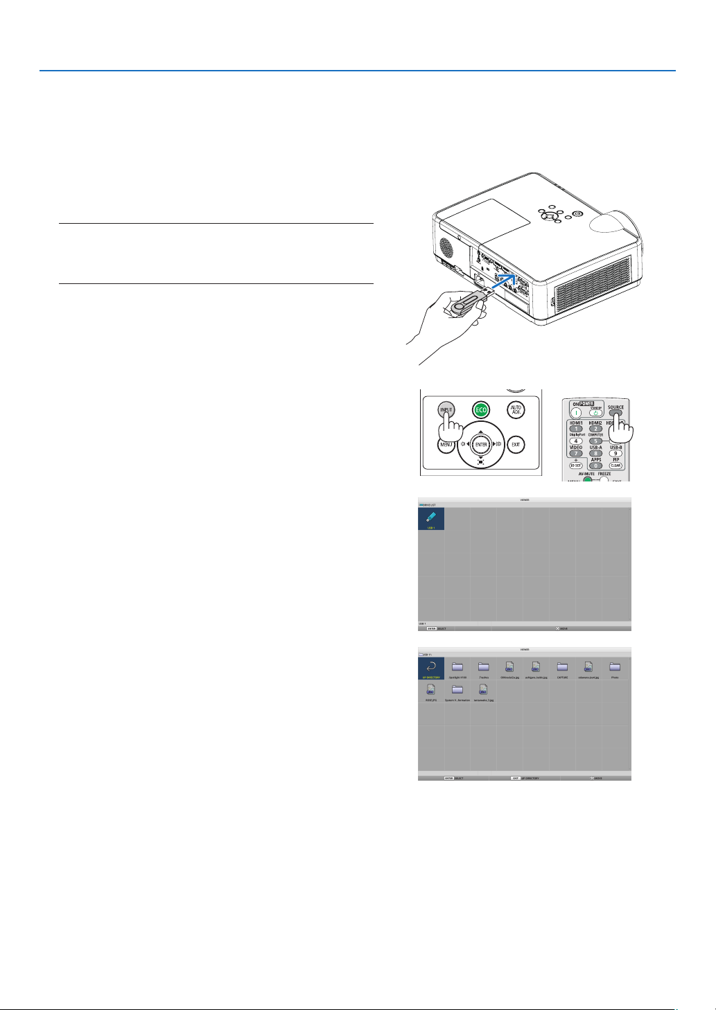
39
4. Using the VIEWER
❷ Projecting the pictures on a USB memory (basic operation)
This section explains the basic operations of the VIEWER. This is the operating procedure when the option menu
(→ page 46) of the VIEWER is in the default state when shipped from the factory.
① Start the VIEWER
1. Turnontheprojector.
2.InsertaUSBmemoryintotheUSB-Aportofthe
projector.
NOTE:
ToremoveaUSBmemoryfromtheprojector,presstheMENU
buttoninthelelistscreenorDRIVELISTscreenandselect
[REMOVEUSBDEVICE].(→Page41“RemovetheUSBmemory”)
3. PresstheINPUTbutton.
The[INPUT]screenisdisplayed.
•PresstheSOURCEbuttonwhenusingtheremote
control.
4. PresstheINPUTbuttonafewtimesandmovethe
cursorto[USB-A].
•EverytimetheINPUTbuttonispressedbriey,the
cursor moves to the next input terminal.
•Movethecursorto[USB-A]andwaitforawhilefor
theVIEWERtostartandtheDRIVELISTscreenonthe
USB memory to be projected.
5. Checkthatthecursorismovedto[USB1]andpress
theENTERbutton.
The file list screen will be displayed.
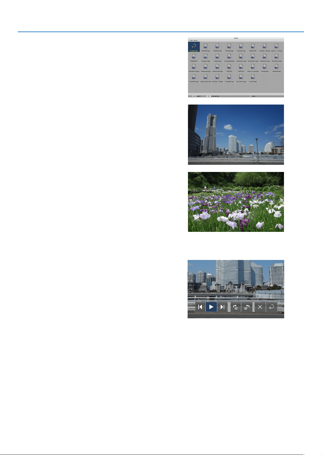
40
4. Using the VIEWER
6. Movethecursortothefolderorimagelewiththe
▲ ▼ ◀ ▶buttonsandpresstheENTERbutton.
•Whenafolderisselected,thelelistscreenforthe
folderisdisplayed.
•Ifanimageleisselected,theslidescreenwillbe
displayed.
7. Movethecursortotheimageleinthelelistscreen,
thenpresstheENTERbutton.
The slide screen will be displayed.
8. Press the ▶ button.
The next image will be projected.
9. Press the ◀ button.
The previous image will be projected.
10.PresstheMENUbutton.
The control bar will be displayed.
•PresstheMENUbuttonwhilethecontrolbarisbeing
displayedtodisplaythe[INPUT]screen.Whenyou
presstheMENUbuttonagain,the[INPUT]screen
disappears.
•WhenyoupresstheEXITbuttonwhilethecontrolbar
is being displayed, the control bar disappears.
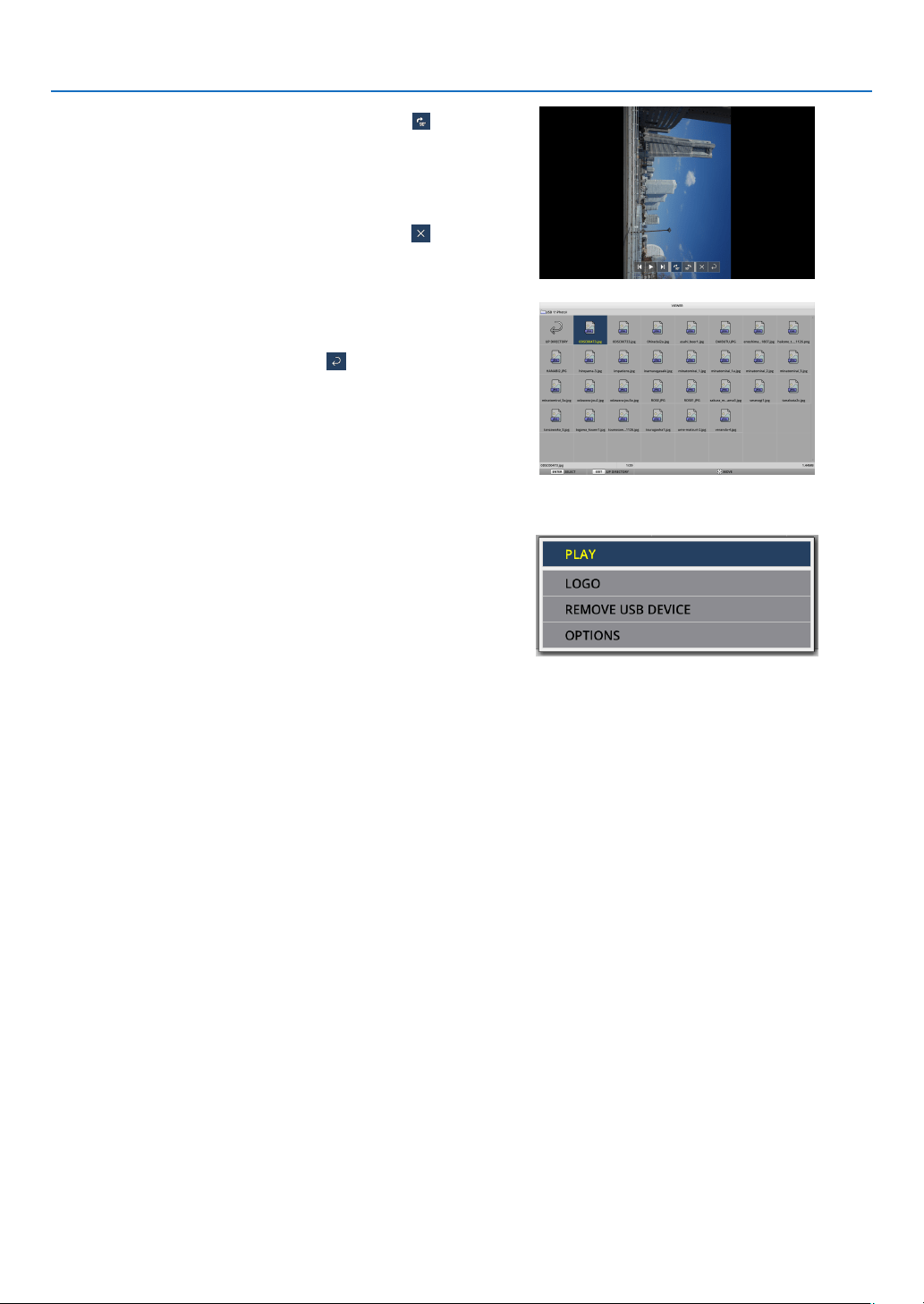
41
4. Using the VIEWER
11. Press the ▶ button to move the cursor to
, then
presstheENTERbutton.
Thepicturewillrotateclockwiseby90°.
•EverytimeyoupresstheENTERbuttoninthisstate,
thepicturerotates90°clockwise.
12. Press the ▶ button to move the cursor to
, then
presstheENTERbutton.
The control bar disappears.
13.PresstheEXITbutton.
The display changes to the file list screen.
•Youcanalsomovethecursorto
with the control bar
ofthestep10andpresstheENTERbuttontochange
the file list screen.
•Toreturntotheslidescreenfromthelelistscreen,
move the cursor to the picture to be displayed in the
slideshow and press the ENTER button.
② Remove the USB memory
1. PresstheMENUbuttoninthelelistscreenordrive
list screen.
Apop-upmenuwillbedisplayedatthebottomleftofthe
screen.
•PresstheMENUbuttonwhilethepop-upmenuis
beingdisplayedtodisplaythe[INPUT]screen.When
youpresstheMENUbuttonagain,the[INPUT]screen
disappears.
•WhenyoupresstheEXITbuttonwhilethepop-up
menu is being displayed, the pop-up menu disappears.
2.Movethecursorto[REMOVEUSBDEVICE]andpress
theENTERbutton.
Aconrmationmessagewillbedisplayedinthecenterof
the screen.
3. ToremovetheUSBmemory,pressthe◀ button to
movethecursorto[OK]andpresstheENTERbutton.
Themessagedisplayedinthecenterofthescreen
changes.
4.PresstheENTERbutton.
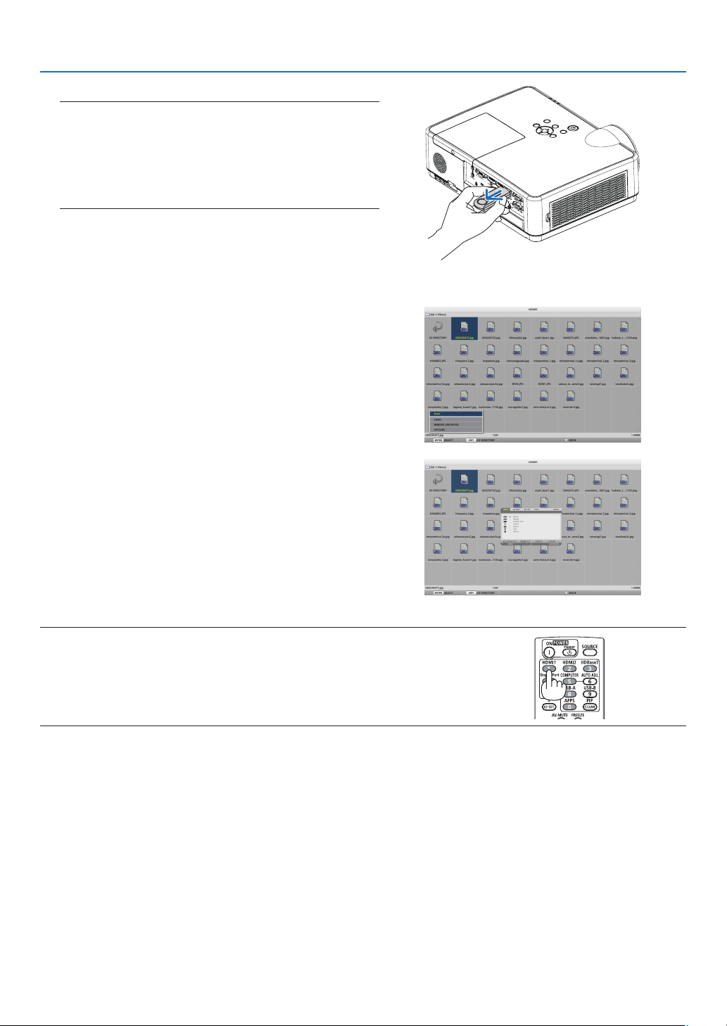
42
4. Using the VIEWER
5. RemovetheUSBmemoryfromtheprojector.
NOTE:
IfyouremoveaUSBmemoryfromtheprojectorwithoutexecuting
[REMOVEUSBDEVICE]inthemenu,theoperationoftheprojector
maybecomeunstable.Inthatcase,turnoffthepowerofthe
projectoronceandunplugthepowercordfromtheoutlet.
Subsequently,waitforabout3minutesbeforeconnectingthe
powercordtothesocketandturningonthepoweroftheprojector.
③ End the VIEWER
1. PresstheMENUbuttonintheslidescreenorlelist
screen.
A control bar or a pop-up menu will be displayed.
2. PresstheMENUbuttonagain.
The[INPUT]screenisdisplayed.
3.Movethecursortoaninputterminalotherthan
[USB-A]andpresstheENTERbutton.
TheVIEWERwillend.
TIP:
•Whenusingtheremotecontrol,presstheHDMI1buttonetc.toendtheVIEWER.
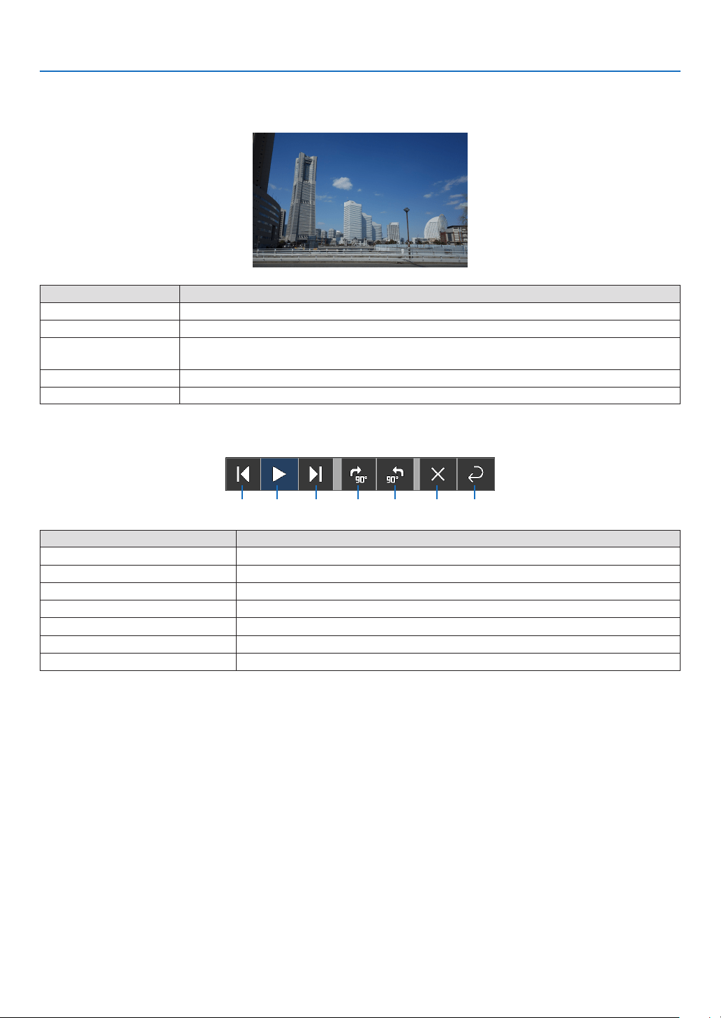
43
4. Using the VIEWER
3 Slide screen operations
The following operations can be performed on the slide screen.
Button name Description
▶, PAGE ▽
Project the next picture.
◀, PAGE △
Project the previous picture.
ENTER
Display the pointer (→). The pointer moves when you press the ▼▲◀▶ button. If you
press the ENTER button again, the pointer disappears.
EXIT Switch to the file list screen.
MENU Display the control bar.
On the control bar, press the ◀ / ▶ button to move the yellow cursor and press the ENTER button at the desired
item. The function of each item is as follows.
②① ③ ④ ⑤ ⑥ ⑦
Items on the control bar Description
① Back
Project the previous picture.
② Play / Stop
Start automatic playback of the slideshow. Or stop the slide show.
③ Next
Project the next picture.
④Rotate90°totheright
Rotatethepictureclockwiseby90°.
⑤Rotate90°totheleft
Rotatethepicturecounter-clockwiseby90°.
⑥ End
Turn off the control bar.
⑦ Return to the file list screen
Switch to the thumbnail screen.
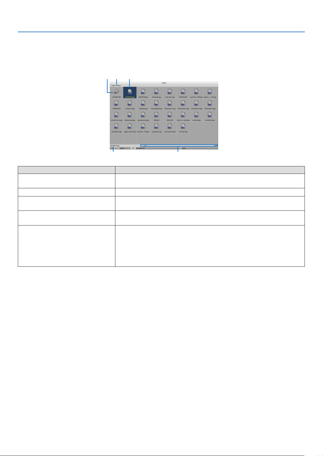
44
4. Using the VIEWER
4 File list screen operations
How to view the file list screen
② ① ③
④ ⑤
Display name Description
① Path
Display the path of the projected folder.
When a USB memory is inserted, the drive name is displayed as “USB”.
② To the upper level
Return to the folder at the upper (parent) level.
③ Picture or folder (icon display or)
thumbnail display
Display pictures and folders as icons or thumbnails (zoom out).
④ File name of the selected
picture
Display the file name of the picture corresponding to the cursor.
⑤ Information display
•Whenthecursorisonapicture,theorderofthepicture(thenumberout
of all the pictures), the latest date and time the picture was updated,
and the file size are displayed.
•Whenthecursorisonafolder,theupdatedateandtimeofthefolderis
displayed.
•Whenthecursorisonadrive,thefreespaceofthedriveisdisplayed.
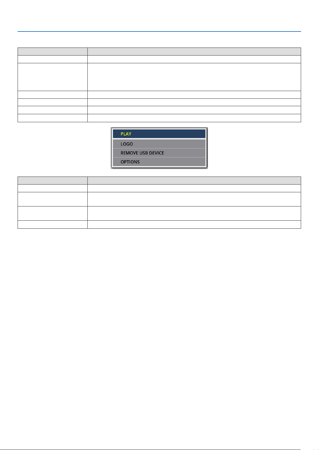
45
4. Using the VIEWER
File list screen operations
Button name Description
▼▲◀▶
Move the cursor.
ENTER •If the cursor is on a picture, the display switches to the slide screen.
•If the cursor is on a folder, the files in the folder are displayed.
•If the cursor is on [UP DIRECTORY], the display returns to the folder in the upper
(parent) level.
EXIT Return to the folder at the upper (parent) level.
MENU Display the following pop-up menu.
PAGE ▽
Display the next file list screen.
PAGE △
Display the previous file list screen.
Menu item Description
PLAY Start the slideshow.
LOGO Change the screen of the input terminal in a signal-less state (background logo) or
the background image of the MultiPresenter start-up screen (MultiPresenter logo).
REMOVE USB DEVICE Disable the use of the USB memory inserted in the projector. Execute this menu
item before removing the USB memory from the projector.
OPTIONS
Display the option menu. (→ page
46)
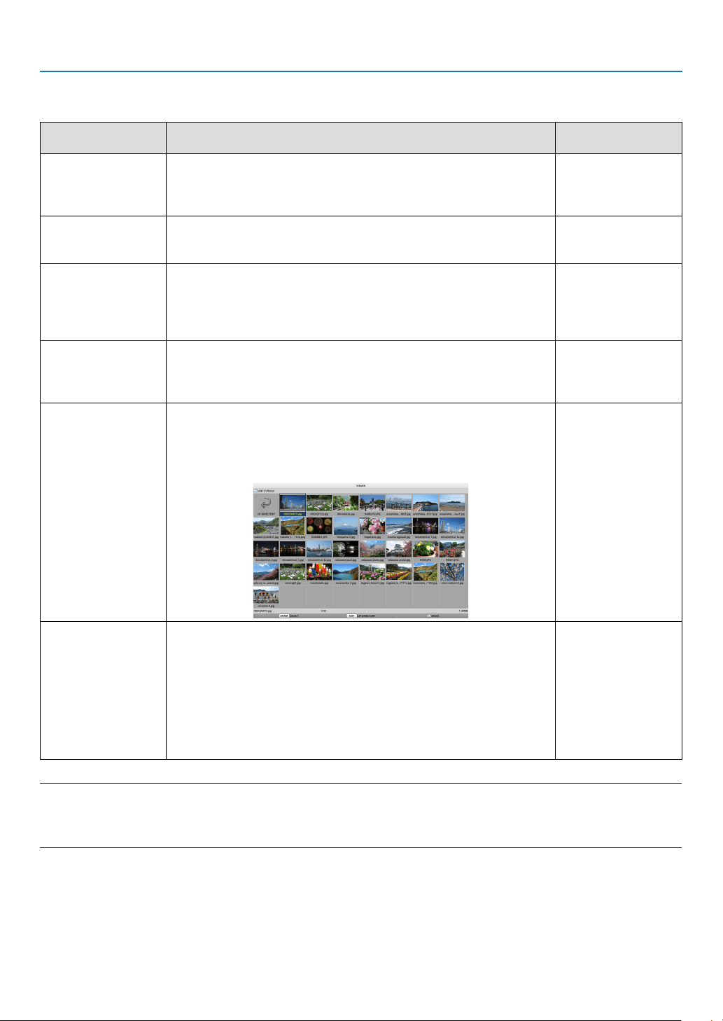
46
4. Using the VIEWER
5 Option menu
Menu item Description
When shipped from
the factory
PLAY MODE Select the display mode of the slide screen.
MANUAL: Switch the picture manually.
AUTOMATIC: Switch the picture automatically according to the
interval setting.
MANUAL
INTERVAL Set the display interval when playing a slideshow automatically.
Selectable range: Set the interval from 5–300 (seconds) by 1
second increment.
5 SECONDS
REPEAT Repeat the slideshow.
•OFF:Donotrepeat.Endtheslideshowafterthelastpictureis
displayed.
•ON:Repeat.Returntotherstpictureafterthelastpictureis
displayed.
OFF
START Set the screen to be displayed when the USB-A terminal is
selected.
•SLIDE:Displaytheslidescreen.
•THUMBNAILS:Displaythelistscreen.
THUMBNAILS
SHOW
THUMBNAILS
Set whether to display the thumbnails of picture files
displayed in
the file list screen.
•OFF:Displayasicons.
•ON:Displayasthumbnails.
Example
OFF
SORT Set the sort order when the file list is displayed.
•NAME(ABC..)/NAME(ZYX..):Displayintheorderofthe
character codes of the files and folder names.
•EXT.(ABC..)/EXT.(ZYX..):Displayintheorderofthecharacter
codes of the extensions.
•DATE(NEW)/DATE(OLD):Displaytheleupdatedate/timein
ascending or descending order.
•SIZE(BIG)/SIZE(SMALL):Displayinascendingordescending
order of file size.
NAME (ABC ..)
TIP:
•About“SaveSetting”
SaveeachsettingimmediatelyafterpressingtheENTERbutton.However,thevaluesetin“SORT”ismaintaineduntilthepoweris
turnedoff,returningto“NAME(ABC..)”thenexttimethepoweristurnedon.
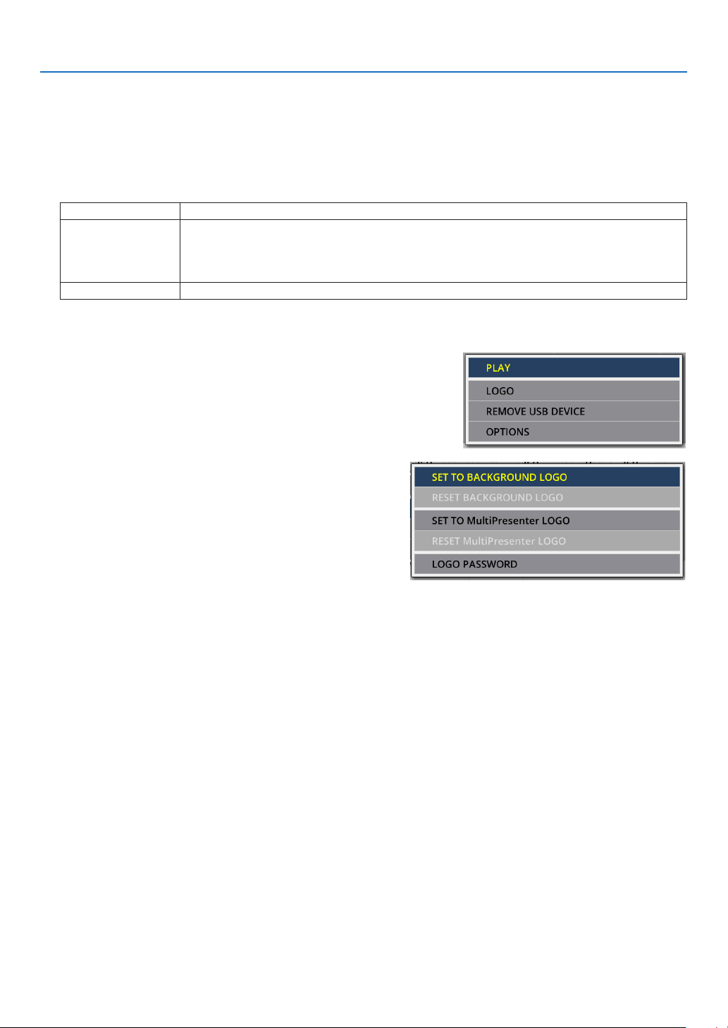
47
4. Using the VIEWER
6 Changing the logo data (background image)
•Youcanchangethescreenoftheinputterminalinasignal-lessstate(backgroundlogo)orthebackgroundimage
of the MultiPresenter start-up screen (MultiPresenter logo).
•Youcanalsosetapasswordtoprohibitthirdpartiesfromchangingthepictures.
•Youcansetpicturesthatsatisfyallofthefollowingconditions.
Format JPEG or PNG pictures that can be displayed with the VIEWER
Resolution Below the panel resolution of the projector
ME382U/ME342U: WUXGA (1920 × 1200)
ME372W/MC382W/MC332W: WXGA (1280 × 800)
ME402X/MC422X/MC372X/MC342X/MC302X: XGA (1024 × 768)
File size 1 megabyte or less
1. Display the file list screen.
2.Movethecursortothepicturetosetinthe
backgroundlogoortheMultiPresenterlogoand
presstheMENUbutton.
The pop-up menu will be displayed.
3.Movethecursorto[LOGO]andpresstheENTER
button.
The sub-menu will be displayed.
① Setting the background logo or MultiPresenter logo
1.Movethecursorto[SETTOBACKGROUNDLOGO]or[SETTOMultiPresenterLOGO]inthesub-menu
andpresstheENTERbutton.
•Ifa[LOGOPASSWORD]hasbeenset,enterthe[LOGOPASSWORD]whenthe[LOGOPASSWORD]input
screen appears.
•Ascreentoconrmwhethertochangethelogoornotisdisplayed.
2.Movethecursorto[YES]andpresstheENTERbutton.
② Initializing the background logo or MultiPresenter logo
1.Movethecursorto[RESETBACKGROUNDLOGO]or[RESETMultiPresenterLOGO]andpresstheENTER
button.
•Ifa[LOGOPASSWORD]hasbeenset,enterthe[LOGOPASSWORD]whenthe[LOGOPASSWORD]input
screen appears.
•Ascreentoconrmwhethertoinitializethelogoornotisdisplayed.
2.Movethecursorto[YES]andpresstheENTERbutton.

48
4. Using the VIEWER
③ Set a password so that the logo will not be changed without authorization
This section explains the procedure for setting the password for the first time.
1.Movethecursorto[LOGOPASSWORD]inthesub-menuandpresstheENTERbutton.
•ThePASSWORDSETTINGscreenisdisplayed.
2.Movethecursorto“NEWPASSWORD”andpresstheENTERbutton.
•Thecharacterinputscreenwillbedisplayed.Enterthepasswordusingthe▲ ▼ ◀ ▶ buttons and press the
ENTER button.
•Only1–10alphanumericcharactersareallowedtobeusedinthepassword.
•Whenthepasswordisentered,itwillbeindicatedbyasterisksintheentryeld.
3.Movethecursorto“CONFIRMNEWPASSWORD”andpresstheENTERbutton.
•Enterthesamepasswordagain.
4.Movethecursorto“OK”onthepasswordsettingscreenandpresstheENTERbutton.
The LOGO PASSWORD will be set.
TIP:
• HowtoerasethesetLOGOPASSWORD
① Movethecursorto“LOGOPASSWORD”inthesub-menuandpresstheENTERbutton.
② PresstheENTERbuttoninthepasswordentryscreen.
③ Enterthepassword,movethecursorto“OK”andpresstheENTERbutton.
ThePASSWORDSETTINGscreenwillbedisplayed.
④ Movethecursorto“NEWPASSWORD”andpresstheENTERbutton.
•Movethecursorto“OK”withoutenteringanythinginthecharacterinputscreenandpresstheENTERbutton.
⑤ Movethecursorto“CONFIRMNEWPASSWORD”andpresstheENTERbutton.
•Movethecursorto“OK”withoutenteringanythinginthecharacterinputscreenandpresstheENTERbutton.
⑥ Movethecursorto“OK”inthepasswordsettingscreenandpresstheENTERbutton.
ThesetLOGOPASSWORDwillnowbedeleted.
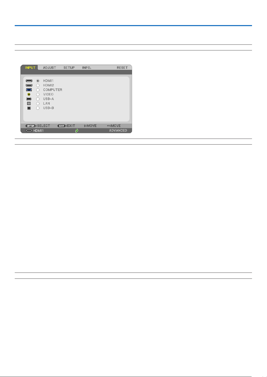
49
5. Using On-Screen Menu
❶ Using the Menus
NOTE:Theon-screenmenumaynotbedisplayedcorrectlywhileinterlacedmotionvideoimageisprojected.
1.PresstheMENUbuttonontheremotecontrolortheprojectorcabinettodisplaythemenu.
NOTE: The commands such as ENTER,EXIT,▲▼,◀▶inthebottomshowavailablebuttonsforyouroperation.
2. Press the ◀▶buttonsontheremotecontrolortheprojectorcabinettodisplaythesubmenu.
3.PresstheENTERbuttonontheremotecontrolortheprojectorcabinettohighlightthetopitemorthe
first tab.
4. Use the ▲▼buttonsontheremotecontrolortheprojectorcabinettoselecttheitemyouwanttoadjust
or set.
Youcanusethe◀▶buttonsontheremotecontrolortheprojectorcabinettoselectthetabyouwant.
5.PresstheENTERbuttonontheremotecontrolortheprojectorcabinettodisplaythesubmenuwindow.
6.Adjustthelevelorturntheselecteditemonoroffbyusingthe▲▼◀▶ buttons on the remote control or
theprojectorcabinet.
Changes are stored until adjusted again.
7.Repeatsteps2-6toadjustanadditionalitem,orpresstheEXITbuttonontheremotecontrolorthepro-
jectorcabinettoquitthemenudisplay.
NOTE:Whenamenuormessageisdisplayed,severallinesofinformationmaybelost,dependingonthesignalorsettings.
8.PresstheMENUbuttontoclosethemenu.
Toreturntothepreviousmenu,presstheEXITbutton.
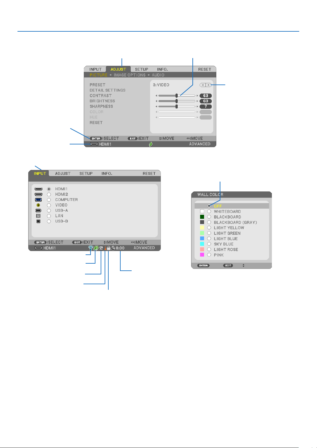
50
5. Using On-Screen Menu
❷
Menu Elements
Slide bar
Solid triangle
Tab
Radio button
Menuwindowsordialogboxestypicallyhavethefollowingelements:
Highlight �������������������������������Indicates the selected menu or item�
Solid triangle �������������������������Indicates further choices are available� A highlighted triangle indicates the item is active�
Tab ����������������������������������������Indicates a group of features in a dialog box� Selecting on any tab brings its page to the front�
Radio button ��������������������������Use this round button to select an option in a dialog box�
Source ����������������������������������Indicates the currently selected source�
Off Timer remaining time �������Indicates the remaining countdown time when the [OFF TIMER] is preset�
Slide bar �������������������������������Indicates settings or the direction of adjustment�
ECO mode symbol �����������������Indicates ECO MODE is set�
Key Lock symbol ������������������� Indicates the [CONTROL PANEL LOCK] is enabled�
Thermometer symbol ������������ Indicates the [ECO MODE] is forcibly set to [NORMAL] mode because the internal temperature is too high�
High Altitude symbol��������������Indicates the [FAN MODE] is set to [HIGH ALTITUDE] mode�
Wireless symbol ��������������������Indicate the wireless LAN connection is enabled�
Source
Available buttons
High Altitude symbol
ECO mode symbol
Wireless symbol
Thermometer symbol
KeyLocksymbol
OffTimerremaining
time
Highlight
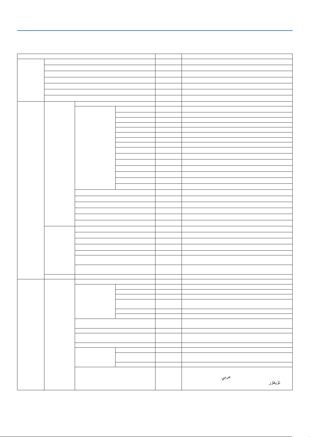
51
5. Using On-Screen Menu
❸ List of Menu Items
Some menu items are not available depending on the input source.
Menu Item Default Options
INPUT
HDMI1 *
HDMI2 *
COMPUTER *
VIDEO *
USB-A *
LAN *
USB-B *
ADJUST
PICTURE
PRESET * 1–7
DETAIL SETTINGS
GENERAL
REFERENCE * HIGH-BRIGHT, PRESENTATION, VIDEO, MOVIE, GRAPHIC, sRGB, DICOM SIM�
GAMMA CORRECTION DYNAMIC, NATURAL, BLACK DETAIL
SCREEN SIZE * LARGE, MEDIUM, SMALL
COLOR TEMPERATURE * 5000-10500
DYNAMIC CONTRAST * OFF, ON
IMAGE MODE * STILL, MOVIE
COLOR ENHANCEMENT * OFF, LOW, MEDIUM, HIGH
WHITE BALANCE
CONTRAST R 0
CONTRAST G 0
CONTRAST B 0
BRIGHTNESS R *
BRIGHTNESS G *
BRIGHTNESS B *
CONTRAST 63
BRIGHTNESS 63
SHARPNESS 7
COLOR 31
HUE 31
RESET
IMAGE OPTIONS
CLOCK *
PHASE *
HORIZONTAL *
VERTICAL *
OVERSCAN * AUTO, 0[%], 5[%], 10[%]
ASPECT RATIO *
WUXGA/WXGA: AUTO, 4:3, 16:9, 15:9, 16:10, LETTERBOX, NATIVE
XGA: AUTO, 4:3, 16:9, 15:9, 16:10, WIDE ZOOM, NATIVE
POSITION (Not available on ME382U/ME342U/
ME372W/MC382W/MC332W)
0
AUDIO VOLUME 11 0–31
SETUP GENERAL
AUTO KEYSTONE ON OFF, ON
KEYSTONE
KEYSTONE HORIZONTAL 0
KEYSTONE VERTICAL 0
PINCUSHION LEFT/RIGHT 0
PINCUSHION TOP/
BOTTOM
0
CORNERSTONE 0
RESET
WALL COLOR OFF
OFF, WHITEBOARD, BLACKBOARD, BLACKBOARD (GRAY), LIGHT YELLOW,
LIGHT GREEN, LIGHT BLUE, SKYBLUE, LIGHT ROSE, PINK
ECO MODE AUTO ECO OFF, AUTO ECO, NORMAL, ECO
CLOSED CAPTION OFF
OFF, CAPTION1, CAPTION2, CAPTION3, CAPTION4, TEXT1, TEXT2, TEXT3,
TEXT4
OFF TIMER OFF OFF, 0:30, 1:00, 2:00, 4:00, 8:00, 12:00, 16:00
ADMINISTRATOR MODE
MENU MODE ADVANCED ADVANCED, BASIC
NOT SAVE SETTING
VALUES
OFF OFF, ON
KEYWORD OFF OFF, ON
LANGUAGE ENGLISH
ENGLISH, DEUTSCH, FRANÇAIS, ITALIANO, ESPAÑOL, SVENSKA, 日本語
DANSK, PORTUGUÊS, ČEŠTINA, MAGYAR, POLSKI, NEDERLANDS, SUOMI
NORSK, TÜRKÇE,
РУССКИЙ,
, Ελληνικά, 简体中文, 한국어, TIẾNG ViỆT
ROMÂNĂ, HRVATSKI, БЪЛГАРСКИ, INDONESIA, , ไทย, , 繁體
中文
* The asterisk (*) indicates that the default setting varies depending on the signal.
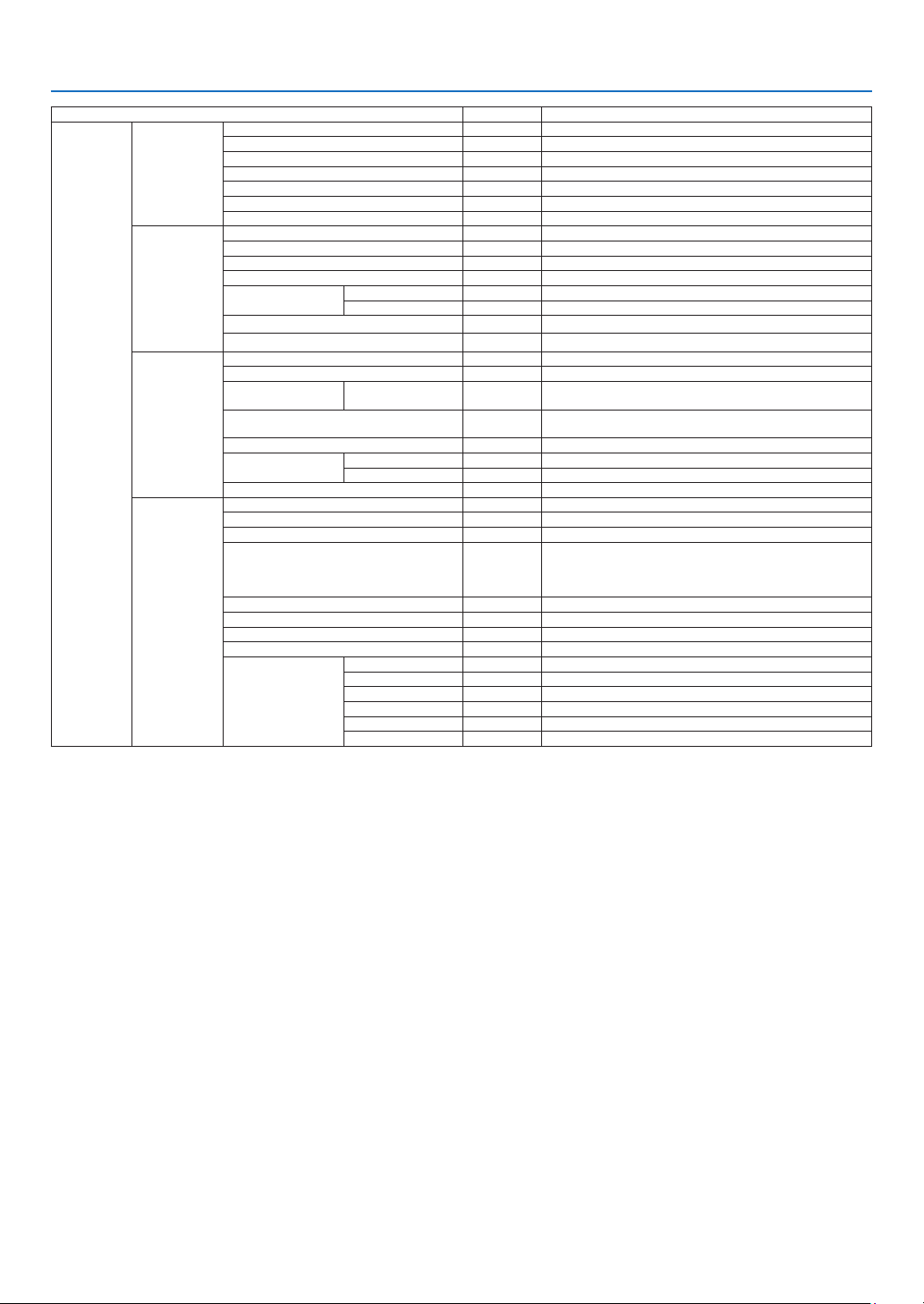
52
5. Using On-Screen Menu
Menu Item Default Options
SETUP
MENU
COLOR SELECT COLOR COLOR, MONOCHROME
INPUT DISPLAY ON OFF, ON
ID DISPLAY ON OFF, ON
ECO MESSAGE OFF OFF, ON
DISPLAY TIME AUTO 45 SEC MANUAL, AUTO 5 SEC, AUTO 15 SEC, AUTO 45 SEC
BACKGROUND BLUE BLUE, BLACK, LOGO
FILTER MESSAGE 10000[H] OFF, 100[H], 500[H], 1000[H], 2000[H], 5000[H], 10000[H]
INSTALLATION
ORIENTATION DESKTOP FRONT DESKTOP FRONT, CEILING REAR, DESKTOP REAR, CEILING FRONT
CONTROL PANEL LOCK OFF OFF, ON
SECURITY OFF OFF, ON
COMMUNICATION SPEED 38400bps 4800bps, 9600bps, 19200bps, 38400bps
CONTROL ID
CONTROL ID NUMBER 1 1–254
CONTROL ID OFF OFF, ON
TEST PATTERN
NETWORK SETTINGS
OPTIONS(1)
SEAMLESS SWITCHING OFF OFF, ON
FAN MODE AUTO AUTO, HIGH ALTITUDE
SIGNAL SELECT COMPUTER
RGB/
COMPONENT
RGB/COMPONENT, RGB, COMPONENT
WXGA MODE
WUXGA/WXGA: ON
XGA: OFF
OFF, ON
DEINTERLACE ON OFF, ON
VIDEO LEVEL
HDMI1 AUTO AUTO, NORMAL, ENHANCED
HDMI2 AUTO AUTO, NORMAL, ENHANCED
BEEP ON OFF, ON
OPTIONS(2)
STANDBY MODE NORMAL NORMAL, NETWORK STANDBY, SLEEP
DIRECT POWER ON OFF OFF, ON
AUTO POWER ON OFF OFF, ON
AUTO POWER OFF
STANDBY
(NORMAL): 1:00
NETWORK
STANDBY: 0:15
OFF, 0:05, 0:10, 0:15, 0:20, 0:30, 1:00
DEFAULT INPUT SELECT LAST LAST, AUTO, HDMI1, HDMI2, COMPUTER, VIDEO, USB-A, LAN, USB-B
CARBON CONVERT
CURRENCY $ $, €, JP¥, RMB¥
CURRENCY CONVERT
STATIC CONVERGENCE
*
1
HORIZONTAL R 0 -1~1
HORIZONTAL G 0 -1~1
HORIZONTAL B 0 -1~1
VERTICAL R 0 -1~1
VERTICAL G 0 -1~1
VERTICAL B 0 -1~1
* The asterisk (*) indicates that the default setting varies depending on the signal.
*1 This feature is not supported by ME372W/MC382W/MC332W/ME402X/MC422X/MC372X/MC342X/MC302X.
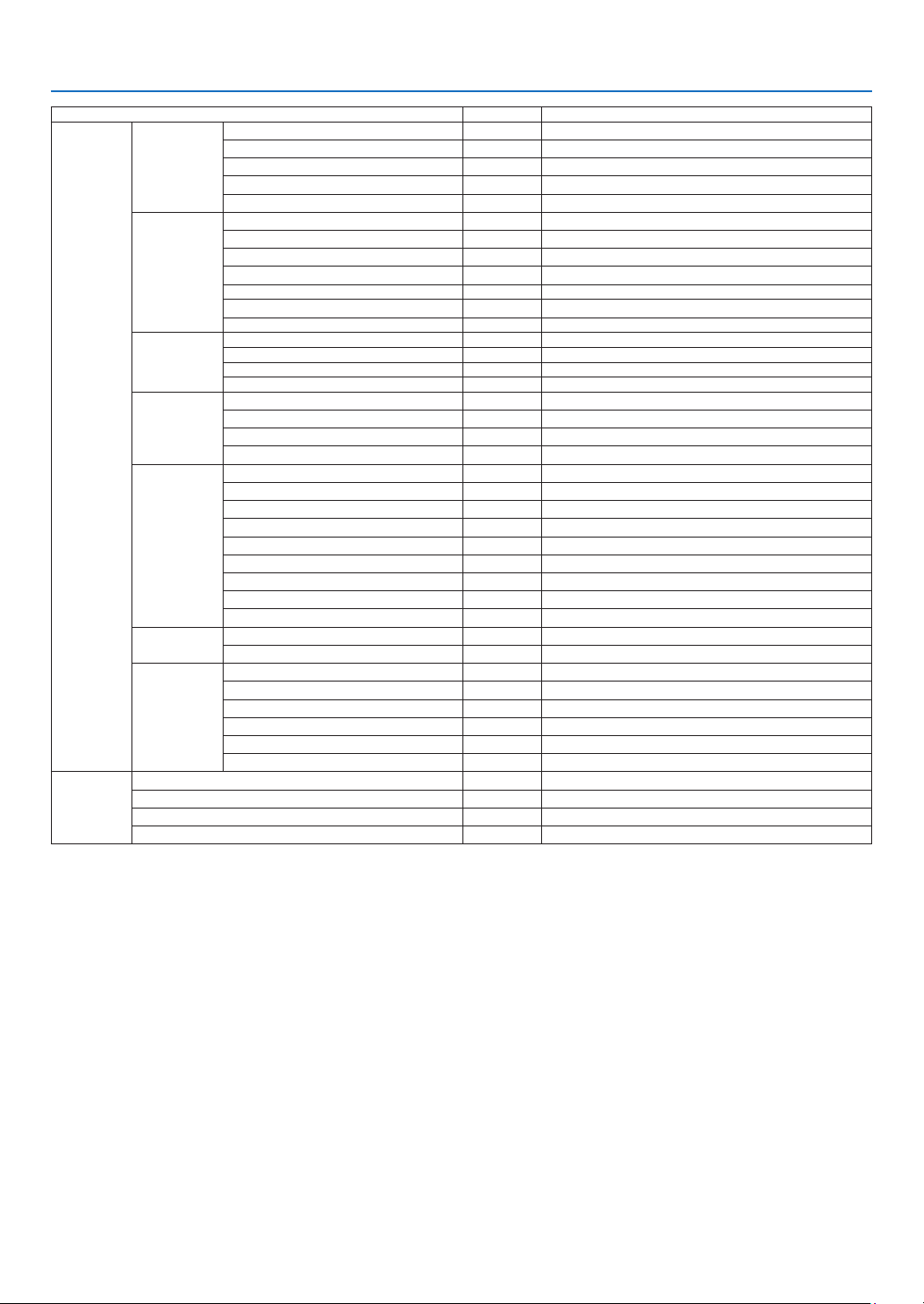
53
5. Using On-Screen Menu
Menu Item Default Options
INFO�
USAGE TIME
LAMP LIFE REMAINING
LAMP HOURS USED
FILTER HOURS USED
TOTAL CARBON SAVINGS
TOTAL COST SAVINGS
SOURCE(1)
SOURCE NAME
SOURCE INDEX
HORIZONTAL FREQUENCY
VERTICAL FREQUENCY
SYNC TYPE SEPARATE SYNC, COMPOSITE SYNC, SYNC ON GREEN, SYNC ON VIDEO
SYNC POLARITY
SCAN TYPE
SOURCE(2)
SIGNAL TYPE
VIDEO TYPE
BIT DEPTH 8[bits], 10[bits], 12[bits]
VIDEO LEVEL
WIRED LAN
IP ADDRESS
SUBNET MASK
GATEWAY
MAC ADDRESS
WIRELESS LAN
IP ADDRESS
SUBNET MASK
GATEWAY
MAC ADDRESS
SSID
NETWORK TYPE
SECURITY
CHANNEL
SIGNAL LEVEL
VERSION
FIRMWARE
DATA
OTHERS
PROJECTOR NAME
HOST NAME
MODEL NO�
SERIAL NUMBER
LAN UNIT TYPE
CONTROL ID (when [CONTROL ID] is set)
RESET
CURRENT SIGNAL
ALL DATA
CLEAR LAMP HOURS
CLEAR FILTER HOURS
* The asterisk (*) indicates that the default setting varies depending on the signal.

54
5. Using On-Screen Menu
❹ Menu Descriptions & Functions [INPUT]
HDMI1 and HDMI2
Selects the HDMI compatible equipment connected to your HDMI1 or 2 IN terminal.
COMPUTER
Selects the computer connected to your COMPUTER input terminal signal.
NOTE:WhenthecomponentinputsignalisconnectedtotheCOMPUTERINterminal,select[COMPUTER].
VIDEO
Selects what is connected to your VIDEO input-VCR, DVD player or document camera.
USB-A
This feature enables you to make presentations using a USB memory that contains slides.
(→ page
38 “4. Using the VIEWER”)
LAN
Selects a signal from the LAN port (RJ-45) or the installed USB wireless LAN unit (optional).
USB-B
Selects the computer connected to the USB-B port by using a commercially available USB cable.
(→ page
34)
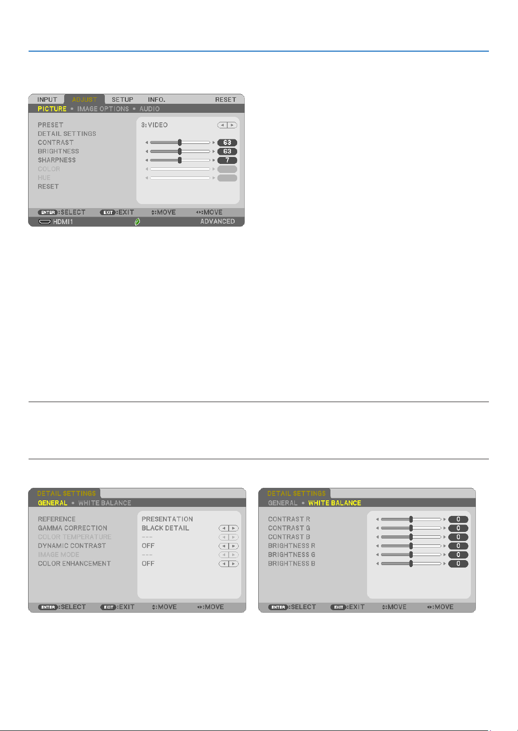
55
5. Using On-Screen Menu
❺ Menu Descriptions & Functions [ADJUST]
[PICTURE]
[PRESET]
This function allows you to select optimized settings for your projected image.
You can adjust neutral tint for yellow, cyan or magenta.
There are seven factory presets optimized for various types of images. You can also use [DETAIL SETTINGS] to set
user adjustable settings to customize each gamma or color.
Your settings can be stored in [PRESET 1] to [PRESET 7].
HIGH-BRIGHT �����������Recommended for use in a brightly lit room�
PRESENTATION ���������Recommended for making a presentation using a PowerPoint file�
VIDEO �����������������������Recommended for typical TV program viewing�
MOVIE ���������������������� Recommended for movies�
GRAPHIC ������������������Recommended for graphics�
sRGB ������������������������Standard color values
DICOM SIM� ��������������Recommended for DICOM simulation format�
NOTE:
•The[DICOMSIM.]optionisfortraining/referenceonlyandshouldnotbeusedforactualdiagnosis.
•DICOMstandsforDigitalImagingandCommunicationsinMedicine.ItisastandarddevelopedbytheAmericanCollegeofRadiology(ACR)
andtheNationalElectricalManufacturersAssociation(NEMA).
Thestandardspecieshowdigitalimagedatacanbemovedfromsystemtosystem.
[DETAILSETTINGS]

56
5. Using On-Screen Menu
[GENERAL]
StoringYourCustomizedSettings[REFERENCE]
This function allows you to store your customized settings in [PRESET 1] to [PRESET 7].
First, select a base preset mode from [REFERENCE], then set [GAMMA CORRECTION] and [COLOR TEMPERATURE].
HIGH-BRIGHT �����������Recommended for use in a brightly lit room�
PRESENTATION ���������Recommended for making a presentation using a PowerPoint file�
VIDEO �����������������������Recommended for typical TV program viewing�
MOVIE ���������������������� Recommended for movies�
GRAPHIC ������������������Recommended for graphics�
sRGB ������������������������Standard color values�
DICOM SIM� ��������������Recommended for DICOM simulation format�
SelectingGammaCorrectionMode[GAMMACORRECTION]
Each mode is recommended for:
DYNAMIC �����������������Creates a high-contrast picture�
NATURAL ������������������Natural reproduction of the picture�
BLACK DETAIL ���������� Emphasizes detail in dark areas of the picture�
NOTE:Thisfunctionisnotavailablewhen[DICOMSIM.]isselectedfor[DETAILSETTINGS].
SelectingScreenSizeforDICOMSIM[SCREENSIZE]
This function will perform gamma correction appropriate for the screen size.
LARGE ����������������������For screen size of 110"
MEDIUM ������������������� For screen size of 90"
SMALL ���������������������For screen size of 70"
NOTE:Thisfunctionisavailableonlywhen[DICOMSIM.]isselectedfor[DETAILSETTINGS].
AdjustingColorTemperature[COLORTEMPERATURE]
This option allows you to select the color temperature of your choice.
NOTE:When[HIGH-BRIGHT]isselectedin[REFERENCE],thisfunctionisnotavailable.
AdjustingBrightnessandContrast[DYNAMICCONTRAST]
This function allows you to adjust the contrast ratio optically using the built-in iris.
To increase the contrast ratio, select [ON].
SelectingStillImageModeorMovieMode[IMAGEMODE]
This function allows you to select the still image mode or the movie mode.
STILL �����������������������This mode is for a still image�
MOVIE ���������������������� This mode is for a movie�
NOTE:Thisfunctionisavailableonlywhen[HIGH-BRIGHT]isselectedfor[REFERENCE].

57
5. Using On-Screen Menu
EnhancingtheColor[COLORENHANCEMENT]
This function allows you to enhance the color of image.
NOTE:Thisfunctionisavailableonlywhen[PRESENTATION]isselected[REFERENCE].
AdjustingWhiteBalance[WHITEBALANCE]
This allows you to adjust the white balance. Contrast for each color (RGB) to adjust the white level of the screen;
Brightness for each color (RGB) is used to adjust the black level of the screen.
[CONTRAST]
Adjusts the intensity of the image according to the incoming signal.
[BRIGHTNESS]
Adjusts the brightness level or the back raster intensity.
[SHARPNESS]
Controls the detail of the image.
[COLOR]
Increases or decreases the color saturation level.
[HUE]
Variesthecolorlevelfrom+/−greento+/−blue.Theredlevelisusedasreference.
Input signal CONTRAST BRIGHTNESS SHARPNESS COLOR HUE
COMPUTER/HDMI (RGB) Yes Yes Yes No No
COMPUTER/HDMI (COMPONENT) Yes Yes Yes Yes Yes
USB-B Yes Yes Yes No No
VIDEO Yes Yes Yes Yes Yes
USB-A/LAN Yes Yes Yes No No
Yes = Adjustable, No = Not adjustable
[RESET]
The settings and adjustments for [PICTURE] will be returned to the factory settings with the exception of the follow-
ing; Preset numbers and [REFERENCE] within the [PRESET] screen.
The settings and adjustments under [DETAIL SETTINGS] within the [PRESET] screen that are not currently selected
will not be reset.
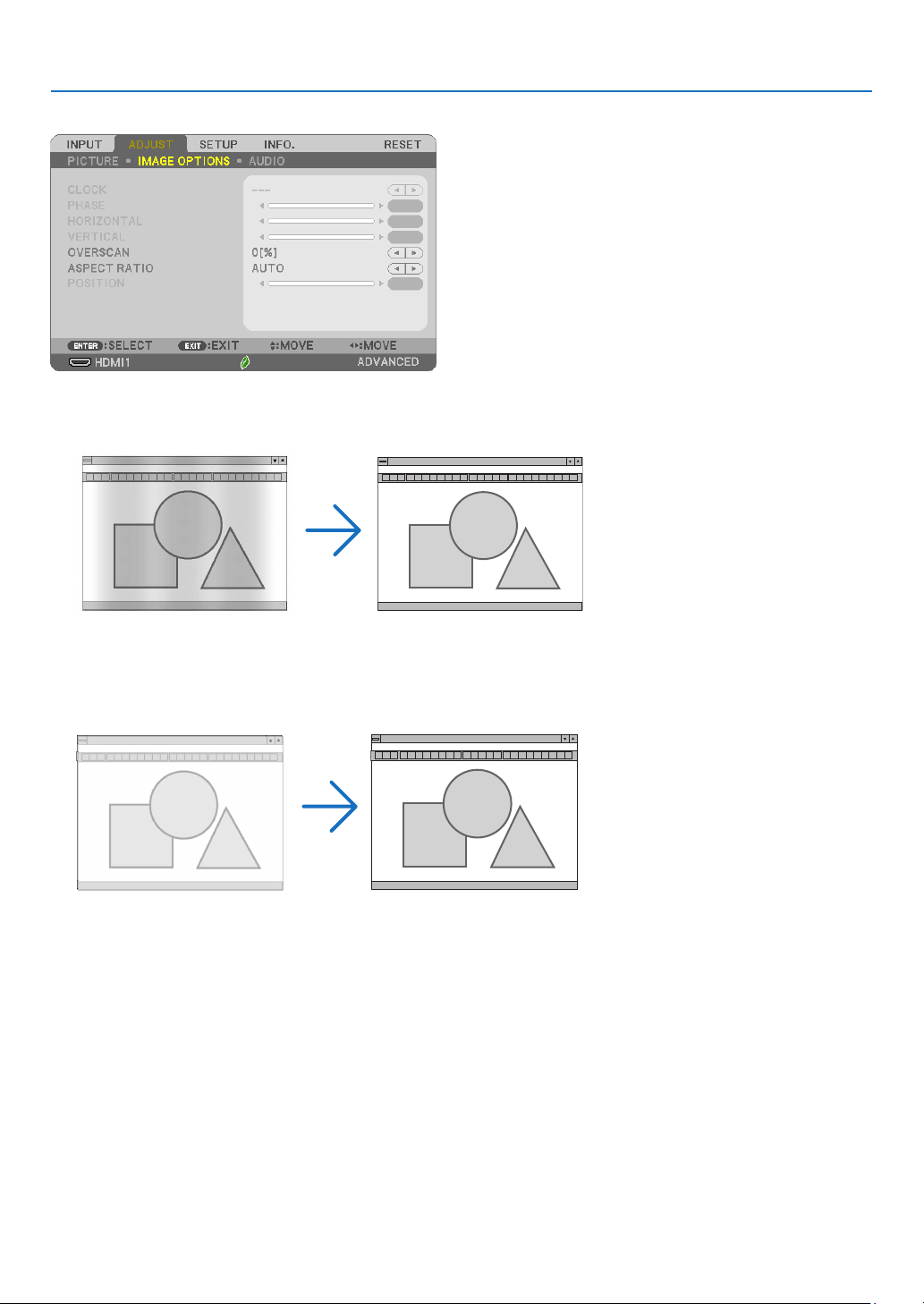
58
5. Using On-Screen Menu
[IMAGE OPTIONS]
AdjustingClockandPhase[CLOCK/PHASE]
This allows you to manually adjust CLOCK and PHASE.
CLOCK ���������������������Use this item to fine tune the computer image or to remove any vertical banding that might appear� This function
adjusts the clock frequencies that eliminate the horizontal banding in the image�
This adjustment may be necessary when you connect your computer for the first time�
PHASE ����������������������Use this item to adjust the clock phase or to reduce video noise, dot interference or cross talk� (This is evident when
part of your image appears to be shimmering�)
Use [PHASE] only after the [CLOCK] is complete�
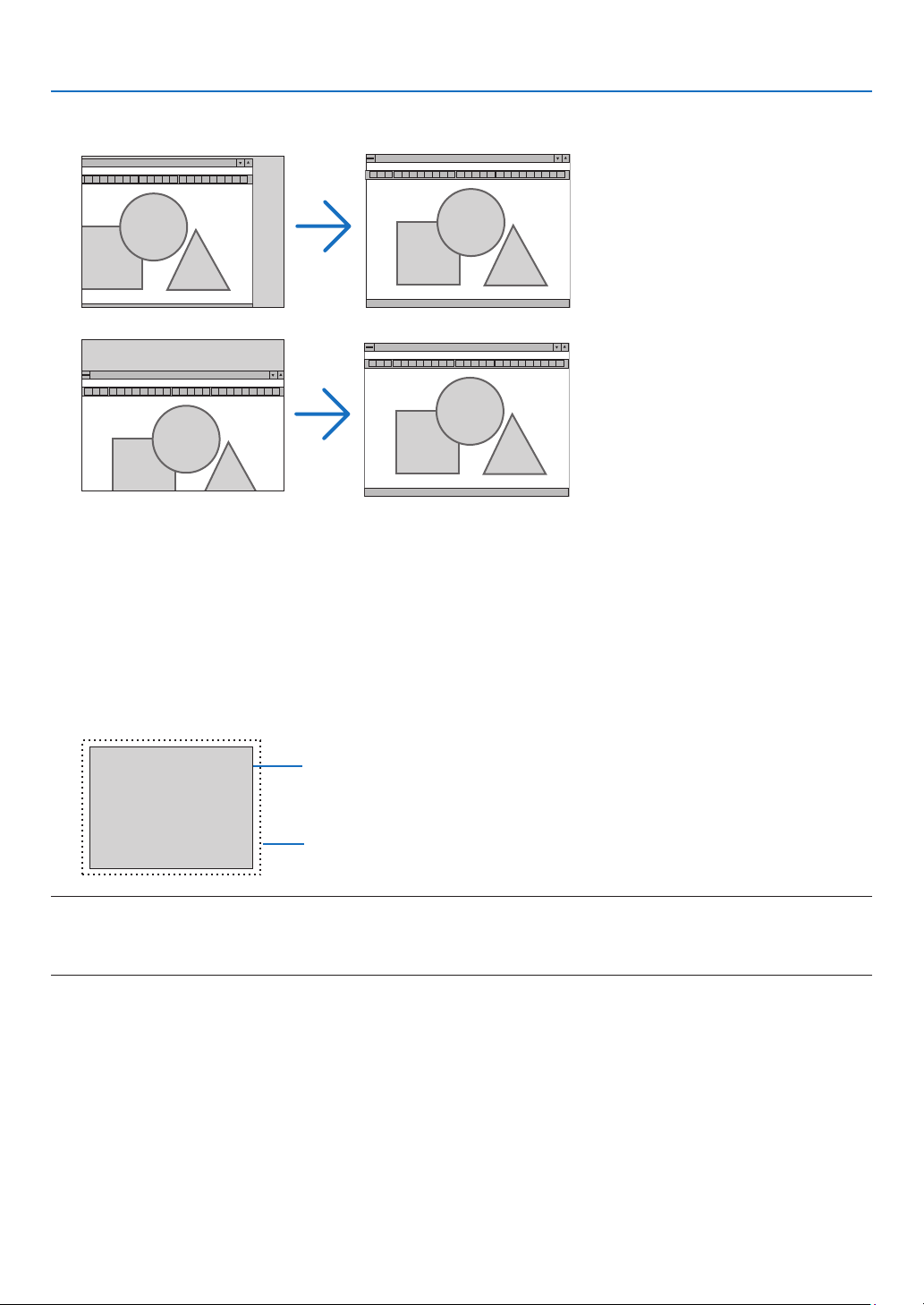
59
5. Using On-Screen Menu
AdjustingHorizontal/VerticalPosition[HORIZONTAL/VERTICAL]
Adjusts the image location horizontally and vertically.
- An image can be distorted during the adjustment of [CLOCK] and [PHASE]. This is not malfunction.
- The adjustments for [CLOCK], [PHASE], [HORIZONTAL], and [VERTICAL] will be stored in memory for the cur-
rent signal. The next time you project the signal with the same resolution, horizontal and vertical frequency, its
adjustments will be called up and applied.
To delete adjustments stored in memory, from the menu, you select [RESET] → [CURRENT SIGNAL] or [ALL
DATA] and reset the adjustments.
SelectingOverscanPercentage[OVERSCAN]
Select overscan percentage (AUTO, 0%, 5% and 10%) for signal.
Projected image
Overscaned by 10%
NOTE:
•The[0[%]]cannotbeselectedwhenVIDEOsignalisused.
•The[OVERSCAN]itemisnotavailable:
-when[NATIVE]isselectedfor[ASPECTRATIO].
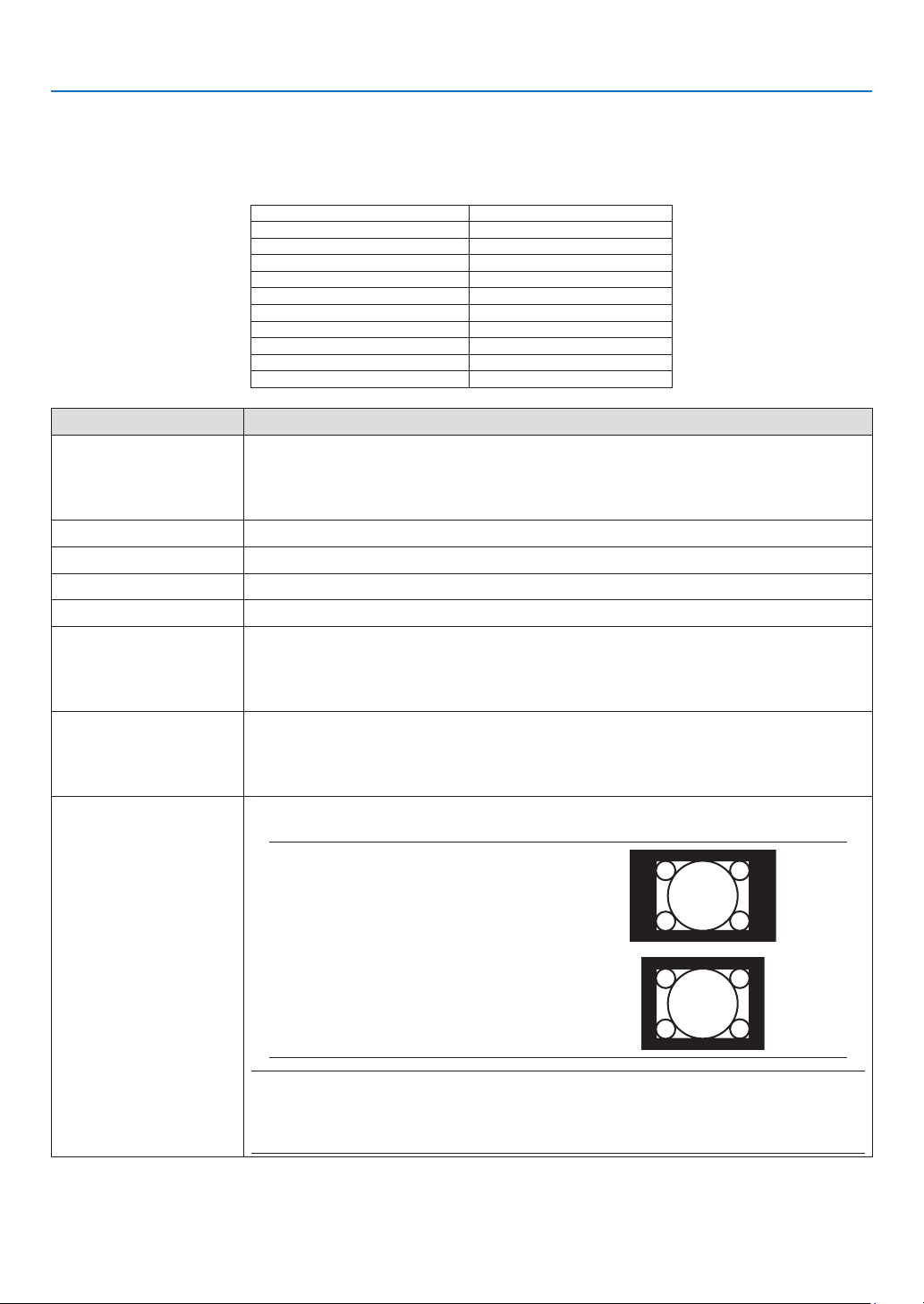
60
5. Using On-Screen Menu
SelectingAspectRatio[ASPECTRATIO]
The term “aspect ratio” refers to the ratio of width to height of a projected image.
The projector automatically determines the incoming signal and displays it in its appropriate aspect ratio.
•Thistableshowstypicalresolutionsandaspectratiosthatmostcomputerssupport.
Resolution Aspect Ratio
VGA 640 × 480 4:3
SVGA 800 × 600 4:3
XGA 1024 × 768 4:3
WXGA 1280 × 768 15:9
WXGA 1280 × 800 16:10
WXGA+1440 × 900 16:10
SXGA 1280 × 1024 5:4
SXGA+1400 × 1050 4:3
UXGA 1600 × 1200 4:3
WUXGA 1920 × 1200 16:10
Options Function
AUTO The projector will automatically determine the incoming signal and display it in its aspect
ratio. (→
next page)
The projector may erroneously determine the aspect ratio depending on its signal. If
this occurs, select the appropriate aspect ratio from the following.
4:3 The image is displayed in 4:3 aspect ratio.
16:9 The image is displayed in 16:9 aspect ratio.
15:9 The image is displayed in 15:9 aspect ratio.
16:10 The image is displayed in 16:10 aspect ratio.
WIDE ZOOM
(ME402X/MC422X/
MC372X/MC342X/
MC302X)
The image is stretched left and right.
Parts of the displayed image are cropped at the left and right edges and therefore not
visible.
LETTERBOX
(ME382U/ME342U/
ME372W/MC382W/
MC332W)
The image of a letterbox signal is stretched equally in the horizontal and vertical direc-
tions to fit the screen. Parts of the displayed image are cropped at the top and bottom
edges and therefore not visible.
NATIVE The projector displays the current image in its true resolution when the incoming com-
puter signal has a lower resolution than the projector’s native resolution.
[Example1] When the incoming
signal with the resolution of 800 ×
600 is displayed on the ME382U/
ME342U/ME372W/MC382W/
MC332W:
[Example2] When the incoming
signal with the resolution of 800 ×
600 is displayed on the ME402X/
MC422X/MC372X/MC342X/
MC302X:
NOTE:
•Whenanon-computersignalisdisplayed,the[NATIVE]isnotavailable.
•Whenasignalwithahigherresolutionthantheprojector’snativeresolutionisdisplayed,[NATIVE]is
notavailable.
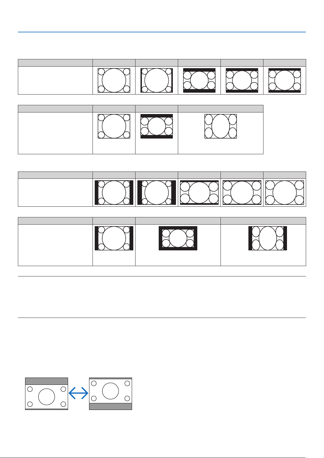
61
5. Using On-Screen Menu
Sampleimagewhentheappropriateaspectratioisautomaticallydetermined
ME402X/MC422X/MC372X/MC342X/MC302X
[Computer signal]
Aspect ratio of incoming signal 4:3 5:4 16:9 15:9 16:10
Sample image when the appro-
priate aspect ratio is automati-
cally determined
[Video signal]
Aspect ratio of incoming signal 4:3 Letterbox Squeeze
Sample image when the aspect
ratio is automatically determined
NOTE:Todisplayasqueezedsignalproperly,
select[16:9]or[WIDEZOOM].
ME382U/ME342U/ME372W/MC382W/MC332W
[Computer signal]
Aspect ratio of incoming signal 4:3 5:4 16:9 15:9 16:10
Sample image when the appro-
priate aspect ratio is automati-
cally determined
[Video signal]
Aspect ratio of incoming signal 4:3 Letterbox Squeeze
Sample image when the aspect
ratio is automatically determined
NOTE:Todisplayaletterboxsignalproperly,
select[LETTERBOX].
NOTE:Todisplayasqueezedsignalproperly,
select[16:9].
TIP:
•Imagepositioncanbeadjustedverticallyusing[POSITION]whenthe[16:9],[15:9],or[16:10]aspectratiosareselected.
•Theterm“letterbox”referstoamorelandscape-orientedimagewhencomparedtoa4:3image,whichisthestandardaspectratiofora
video source.
Theletterboxsignalhasaspectratioswiththevistasize“1.85:1”orcinemascopesize“2.35:1”formovielm.
•Theterm“squeeze”referstothecompressedimageofwhichaspectratioisconvertedfrom16:9to4:3.
AdjustingtheVerticalPositionofImage[POSITION](notavailableonME382U/ME342U/
ME372W/MC382W/MC332W)
(only when [16:9], [15:9], or [16:10] is selected for [ASPECT RATIO])
When [16:9], [15:9], or [16:10] is selected in [ASPECT RATIO], the image is displayed with black borders on the top
and bottom.
You can adjust the vertical position from the top to the bottom of the black area.

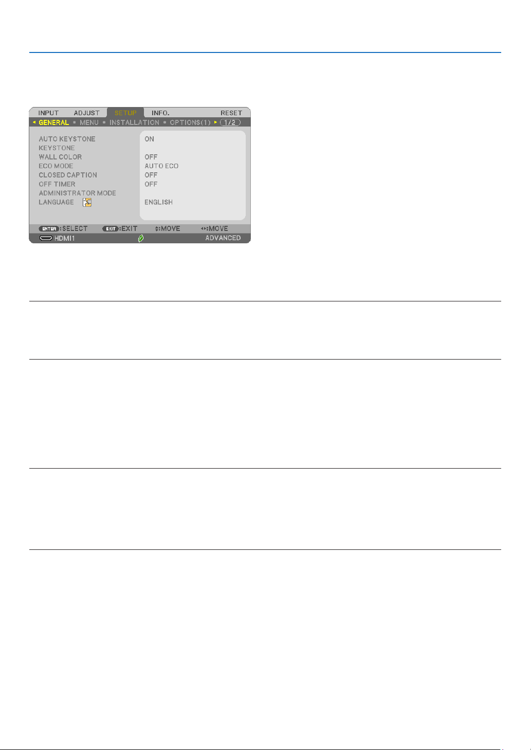
63
5. Using On-Screen Menu
❻ Menu Descriptions & Functions [SETUP]
[GENERAL]
EnablingAutoKeystone[AUTOKEYSTONE]
This feature allows the projector to detect its tilt and correct vertical distortion automatically.
To turn on the AUTO KEYSTONE feature, select [ON]. To adjust the KEYSTONE feature manually, select [OFF].
NOTE:
•The[AUTOKEYSTONE]functionisnotavailablewhenanorientationtypesuchas[CEILINGREAR],[DESKTOPREAR],[CEILINGFRONT]
otherthan[DESKTOP/FRONT]isselectedfor[ORIENTATION].
•Whilethe[AUTOKEYSTONE]is[ON],thefollowingfunctionsarenotavailable,[PINCUSHIONLEFT/RIGHT],[PINCUSHIONTOP/BOTTOM],
and[CORNERSTONE].
TIP
•Adjustableanglerangebythe[AUTOKEYSTONE]isapprox.30degreesinverticaldirection.
•Duringprojectingimage,[AUTOKEYSTONE]willbestartedtoperformapprox.2secondsafterxingthethrowangle.
CorrectingKeystoneDistortionManually[KEYSTONE]
You can correct horizontal or vertical keystone, pincushion LEFT/RIGHT or TOP/BOTTOM, or cornerstone distortion
manually.
NOTE:
•[KEYSTONEHORIZONTAL]and[KEYSTONEVERTICAL]canbeadjustedatonce.
•Tochangefromoneitemtoanotheritem,resettherstitem.
•Adjustmentvalueswillbeoverwritten.Theywillnotbedeletedevenwhentheprojectoristurnedoff.
•Using[KEYSTONE],[PINCUSHION]and[CORNERSTONE]correctioncancausetheimagetobeslightlyblurredbecausethecorrectionis
madeelectronically.
•Whenthe[AUTOKEYSTONE]hasbeen[ON],itautomaticallyperformsverticalkeystonecorrectioneverytimetheprojectorispoweredon.
KEYSTONE HORIZONTAL ���������������Corrects horizontal keystone distortion� (→ page
18)
KEYSTONE VERTICAL ��������������������Corrects vertical keystone distortion� (→ page
18)
PINCUSHION LEFT/RIGHT ��������������Corrects pincushion distortion at the left or right side� (→ page
28)
PINCUSHION TOP/BOTTOM �����������Corrects pincushion distortion at the top or bottom side� (→ page
28)
CORNERSTONE ����������������������������Fits a projected image within the border of the screen easily by align the four corner of an image to
the ones of the screen� (→ page
26)
RESET ������������������������������������������Returns all the above items to the factory preset values�
TIP:
•Adjustableanglerangeinhorizontalandverticaldirectioninthecornerstoneandthekeystonecorrections:Approx.30degrees(Max)
-Dependingoninputsignal,theadjustablerangemaybenarrower.
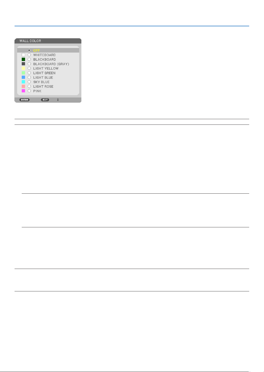
64
5. Using On-Screen Menu
UsingtheWallColorCorrection[WALLCOLOR]
This function allows for quick adaptive color correction in applications where the screen material is not white.
NOTE:Selecting[WHITEBOARD]reduceslampbrightness.
SettingEcoMode[ECOMODE]
The ECO MODE increases lamp life, while lowering power consumption and cutting down on CO
2
emissions.
Four brightness modes of the lamp can be selected: [OFF], [AUTO ECO], [NORMAL] and [ECO] modes.
(→ page
24)
SettingClosedCaption[CLOSEDCAPTION]
This option sets several closed caption modes that allow text to be superimposed on the projected image of Video.
OFF �������������������������� This exits the closed caption mode�
CAPTION 1-4 ������������ Text is superimposed�
TEXT 1-4 ������������������Text is displayed�
NOTE:
•Theclosedcaptionisnotavailableunderthefollowingconditions:
-whenmessagesormenusaredisplayed.
-whenanimageismagnied,frozen,ormuted.
•Portionsofsuperimposedtextorclosedcaptionmaybetruncated.Ifthathappens,trytoplacethesuperimposedtextorclosedcaption
withinthescreen.
UsingOffTimer[OFFTIMER]
1.Selectyourdesiredtimebetween30minutesand16hours:OFF,0:30,1:00,2:00,4:00,8:00,12:00,16:00.
2.PresstheENTERbuttonontheremotecontrol.
3.Theremainingtimestartscountingdown.
4.Theprojectorwillturnoffafterthecountdowniscomplete.
NOTE:
•Tocancelthepresettime,set[OFF]forthepresettimeorturnoffthepower.
•Whentheremainingtimereaches3minutesbeforetheprojectoristurnedoff,the[THEPROJECTORWILLTURNOFFWITHIN3MINUTES]
messagewillbedisplayedonthebottomofthescreen.
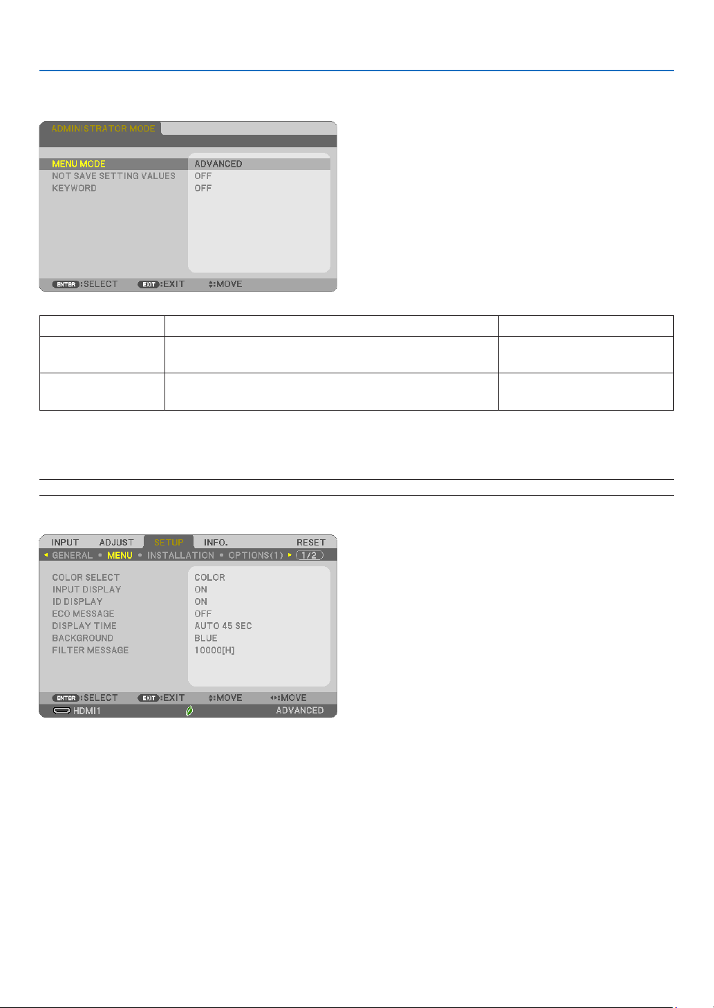
65
5. Using On-Screen Menu
ADMINISTRATORMODE
This allows you to select MENU MODE, save settings, and set a password for the administrator mode.
MENU MODE Select either [BASIC] or [ADVANCED] menu. —
NOT SAVE SETTING
VALUES
Placing a check mark will not save your projector settings.
Clear this check box to save your projector settings.
—
KEYWORD Assign a password for the administrator mode. Up to 10 alphanumeric
characters
SelectingMenuLanguage[LANGUAGE]
You can choose one of 30 languages for on-screen instructions.
NOTE:Yoursettingwillnotbeaffectedevenwhen[RESET]isdonefromthemenu.
[MENU]
SelectingMenuColor[COLORSELECT]
You can choose between two options for menu color: COLOR and MONOCHROME.
TurningOn/OffSourceDisplay[INPUTDISPLAY]
This option turns on or off input name display such as HDMI1, HDMI2, COMPUTER, VIDEO, USB-A, LAN, USB-B,
to be displayed on the top right of the screen.
When no input signal is present, the no-signal guidance prompting you to check for an available input will be displayed.
When the [USB-A] or [LAN] item is selected for [INPUT], the no-signal guidance will not be displayed.
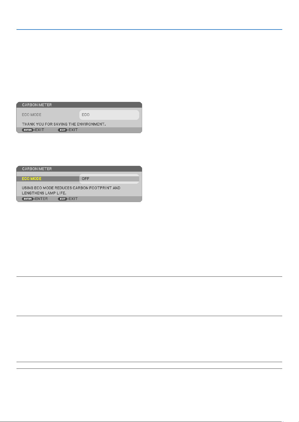
66
5. Using On-Screen Menu
TurningON/OFFControlID[IDDISPLAY]
This option turns on or off the ID number which is displayed when the ID SET button on the remote control is pressed.
TurningOn/OffEcoMessage[ECOMESSAGE]
This option turns on or off the following messages when the projector is turned on.
The Eco Message prompts the user to save energy. When [OFF] is selected for [ECO MODE], you will get a message
to prompt you to select [AUTO ECO], [NORMAL], or [ECO] for [ECO MODE].
When [AUTO ECO], [NORMAL], or [ECO] is selected for [ECO MODE]
To close the message, press any one of the buttons. The message will disappear if no button operation is done for
30 seconds.
When [OFF] is selected for [ECO MODE]
Pressing the ENTER button will display the [ECO MODE] screen. (→ page 24)
To close the message, press the EXIT button.
SelectingMenuDisplayTime[DISPLAYTIME]
This option allows you to select how long the projector waits after the last touch of a button to turn off the menu.
The preset choices are [MANUAL], [AUTO 5 SEC], [AUTO 15 SEC], and [AUTO 45 SEC]. The [AUTO 45 SEC] is the
factory preset.
SelectingaColororLogoforBackground[BACKGROUND]
Use this feature to display a blue/black screen or logo when no signal is available. The default background is [BLUE].
NOTE:
•Ifthe[LOGO]itemisselectedfor[BACKGROUND]withthe[LAN]or[USB-B]sourceselected,the[BLUE]itemwillbeselectedregardless
ofitsselection.
•When[INPUTDISPLAY]isturnedon,theno-signalguidancepromptingyoutocheckforanavailableinputwillbedisplayedatthecenter
ofthescreenregardlessofitsselection.
•Yoursettingwillnotbeaffectedevenwhen[RESET]isdonefromthemenu.
SelectingIntervalTimeforFilterMessage[FILTERMESSAGE]
This option allows you to select the time preference between displaying the message for cleaning the filter. Clean
the filter when you get the message “PLEASE CLEAN THE FILTER.” (→ page
108)
Seven options are available:
OFF, 100[H], 500[H], 1000[H], 2000[H], 5000[H], 10000[H]
NOTE:Yoursettingwillnotbeaffectedevenwhen[RESET]isdonefromthemenu.
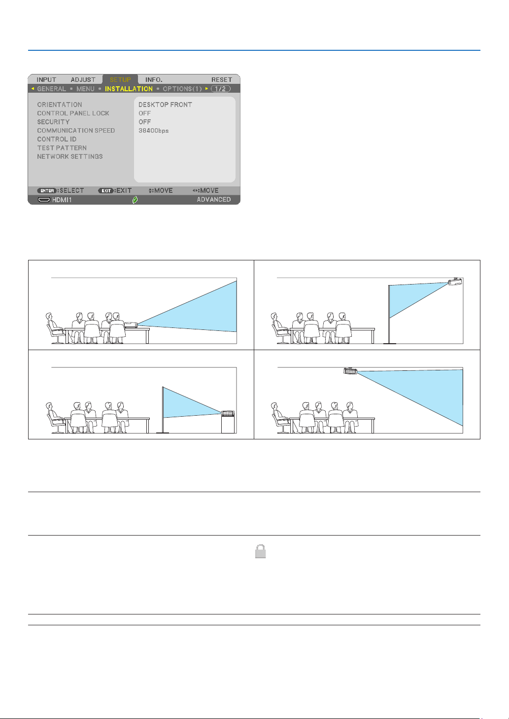
67
5. Using On-Screen Menu
[INSTALLATION]
SelectingProjectorOrientation[ORIENTATION]
This reorients your image for your type of projection. The options are: desktop front projection, ceiling rear projec-
tion, desktop rear projection, and ceiling front projection.
DESKTOP FRONT CEILING REAR
DESKTOP REAR CEILING FRONT
DisablingtheCabinetButtons[CONTROLPANELLOCK]
This option turns on or off the CONTROL PANEL LOCK function.
NOTE:
•ThisCONTROLPANELLOCKdoesnotaffecttheremotecontrolfunctions.
•Whenthecontrolpanelislocked,pressingandholdingtheINPUTbuttonontheprojectorcabinetforabout10secondswillchangethe
settingto[OFF].
TIP:Whenthe[CONTROLPANELLOCK]isturnedon,akeylockicon[
]willbedisplayedatthebottomrightofthemenu.
EnablingSecurity[SECURITY]
This feature turns on or off the SECURITY function.
Unless the correct keyword is entered, the projector cannot project an image. (→ page
30)
NOTE:Yoursettingwillnotbeaffectedevenwhen[RESET]isdonefromthemenu.
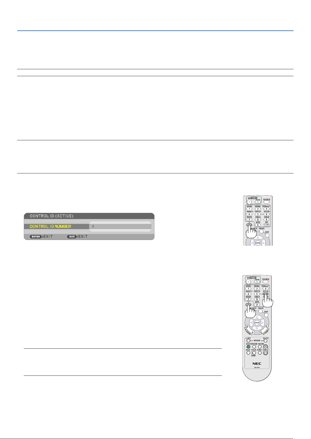
68
5. Using On-Screen Menu
SelectingCommunicationSpeed[COMMUNICATIONSPEED]
This feature sets the baud rate of the PC Control port (D-Sub 9P). It supports data rates from 4800 to 38400 bps.
The default is 38400 bps. Select the appropriate baud rate for your equipment to be connected (depending on the
equipment, a lower baud rate may be recommended for long cable runs).
NOTE:Yourselectedcommunicationspeedwillnotbeaffectedevenwhen[RESET]isdonefromthemenu.
SettingIDtotheProjector[CONTROLID]
You can operate multiple projectors separately and independently with the single remote control that has the CON-
TROL ID function. If you assign the same ID to all the projectors, you can conveniently operate all the projectors
together using the single remote control. To do so, you have to assign an ID number to each projector.
CONTROL ID NUMBER ����������� Select a number from 1 to 254 you wish to assign to your projector�
CONTROL ID ��������������������������Select [OFF] to turn off the CONTROL ID setting and select [ON] to turn on the CONTROL ID setting�
NOTE:
•When[ON]isselectedfor[CONTROLID],theprojectorcannotbeoperatedbyusingtheremotecontrolthatdoesnotsupporttheCONTROL
IDfunction.(Inthiscase,thebuttonsontheprojectorcabinetcanbeused.)
•Yoursettingwillnotbeaffectedevenwhen[RESET]isdonefromthemenu.
•PressingandholdingtheENTERbuttonontheprojectorcabinetfor10secondswilldisplaythemenuforcancelingtheControlID.
AssigningorChangingtheControlID
1.Turnontheprojector.
2.PresstheIDSETbuttonontheremotecontrol.
TheCONTROLIDscreenwillbedisplayed.
IftheprojectorcanbeoperatedwiththecurrentremotecontrolID,the[ACTIVE]will
bedisplayed.Iftheprojectorcannotbeoperatedwiththecurrentremotecontrol
ID,the[INACTIVE]willbedisplayed.Tooperatetheinactiveprojector,assignthe
controlIDusedfortheprojectorbyusingthefollowingprocedure(Step3).
3.PressoneofnumerickeypadbuttonswhilepressingandholdingtheIDSET
button on the remote control.
Example:
Toassign“3”,pressthe“3”buttonontheremotecontrol.
NoIDmeansthatalltheprojectorscanbeoperatedtogetherwithasingleremote
control.Toset“NoID”,enter“000”orpresstheCLEARbutton.
TIP:TherangeofIDsisfrom1to254.
4.ReleasetheIDSETbutton.
TheupdatedCONTROLIDscreenwillbedisplayed.
NOTE:
•TheIDscanbeclearedinafewdaysafterthebatteriesarerundownorremoved.
•AccidentallypressinganyoneofthebuttonsoftheremotecontrolwillclearcurrentlyspeciedID
withbatteriesremoved.
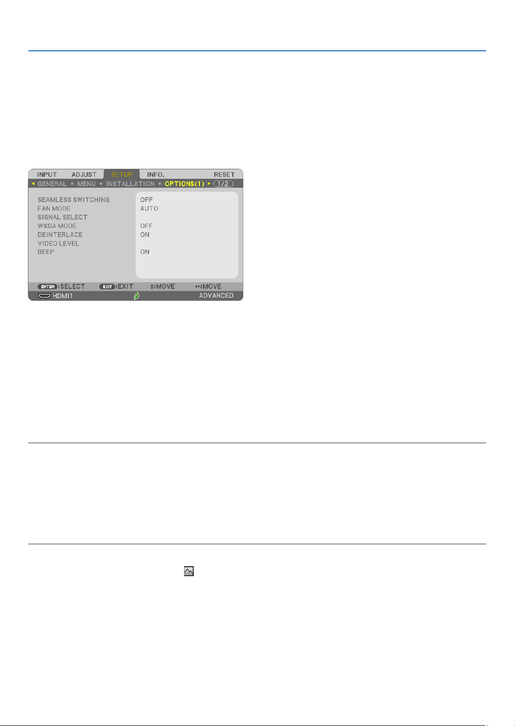
69
5. Using On-Screen Menu
UsingTestPattern[TESTPATTERN]
Displays the test pattern to check for image distortion at the time of the projector setup. Press the ENTER button to
display the test pattern; press the EXIT button to close the test pattern and return to the menu. Menu operation and
corrections for keystone, cornerstone and pincushion are not available when the test pattern is displayed.
[NETWORKSETTINGS]
For details on each of the [NETWORK SETTINGS], see “7-3. NETWORK SETTINGS” (→ page
99).
[OPTIONS(1)]
[SEAMLESSSWITCHING]
When the input connector is switched, the image displayed before switching is held to switch to the new image
without a break due to absence of a signal.
SelectingFanMode[FANMODE]
This option allows you to select two modes for fan speed: Auto mode and High Altitude mode.
AUTO �����������������������The built-in fans automatically run at a variable speed according to the internal temperature�
HIGH ALTITUDE ��������� The built-in fans run at a high speed� Select this option when using the projector at altitudes approximately 5500
feet/1700 meters or higher�
NOTE:
•Set[FANMODE]to[HIGHALTITUDE]whenusingtheprojectorataltitudesapproximately5500feet/1700metersorhigher.
•Usingtheprojectorataltitudesapproximately5500feet/1700metersorhigherwithoutsettingto[HIGHALTITUDE]cancausetheprojector
tooverheatandtheprotectorcouldshutdown.Ifthishappens,waitacoupleminutesandturnontheprojector.
•Usingtheprojectorataltitudeslessthanapproximately5500feet/1700metersandsettingto[HIGHALTITUDE]cancausethelampto
overcool,causingtheimagetoicker.Switch[FANMODE]to[AUTO].
•Usingtheprojectorataltitudesapproximately5500feet/1700metersorhighercanshortenthelifeofopticalcomponentssuchasthe
lamp.
•Yoursettingwillnotbeaffectedevenwhen[RESET]isdonefromthemenu.
TIP:
•When[HIGHALTITUDE]isselected,anicon[
]isdisplayedatthebottomoftheon-screenmenu.

70
5. Using On-Screen Menu
SelectingSignalFormat[SIGNALSELECT]
[COMPUTER]
Allows you to choose [COMPUTER] for an RGB source such as a computer, or [COMPONENT] for a component
video source such as a DVD player. Normally select [RGB/COMPONENT] and the projector automatically detects a
component signal. However there may be some component signals that the projector is unable to detect. If this is
the case, select [COMPONENT].
EnablingorDisablingWXGAMode[WXGAMODE]
Selecting [ON] will give priority to WXGA (1280 × 800)/WUXGA (1920 × 1200) signals in recognizing an input signal.
When [WXGA MODE] is set to [ON], XGA (1024 × 768)/UXGA (1600 × 1200) signals may not be recognized on ME402X/
MC422X/MC372X/MC342X/MC302X. In this case, select [OFF].
NOTE:
•[OFF]isselectedatthetimeofshipmentofME402X/MC422X/MC372X/MC342X/MC302X.
•[ON]isselectedatthetimeofshipmentofME382U/ME342U/ME372W/MC382W/MC332W.
Enablingthedeinterlace[DEINTERLACE]
Turns on or off the deinterlace function for a telecine signal.
OFF �������������������������� Select this option if there is any jitter or artifacts in video�
ON ���������������������������Default standard setting�
NOTE:ThisfeatureisnotavailableforHDTV(progressive)andcomputersignals.
SettingVideoLevel[VIDEOLEVEL]
Selection of the video signal level when connecting an external device to the HDMI 1 IN terminal or HDMI 2 IN terminal
of the projector.
AUTO �����������������������The video level is switched automatically based on the information from the device outputting the signal�
Depending on the connected device, this setting may not be made properly� In this case, switch to “NORMAL” or
“ENHANCED” from the menu and view with the optimum setting�
NORMAL ������������������This disables the enhanced mode�
ENHANCED ���������������This improves the image’s contrast, expressing the dark and light sections more dynamically�
EnablingKeySoundandErrorSound[BEEP]
This feature turns on or off the button sound or alarm when an error occurs or the following operations are performed.
- Displaying the main menu
- Switching sources
- Resetting data by using [RESET]
- Pressing POWER ON or STANDBY button
TIP:
•Volumecontrolfor[BEEP]isdisabled.AV-MUTEbuttonisnoteffectivetostopbeepingsound.IfyouwanttoactivateBEEPfunction,set
[BEEP]to[OFF].
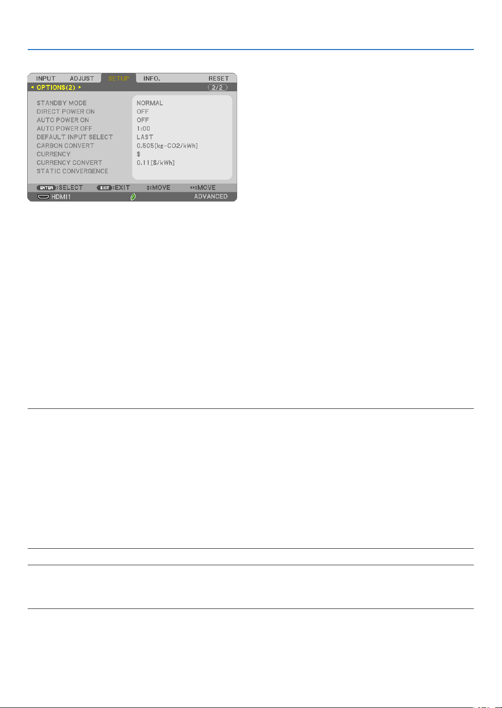
71
5. Using On-Screen Menu
[OPTIONS(2)]
SelectingPower-savingin[STANDBYMODE]
The projector has three standby modes: [NORMAL], [NETWORK STANDBY], and [SLEEP].
The NORMAL mode is the mode that allows you to put the projector in the power-saving condition which consumes
less power than the NETWORK STANDBY mode.
NORMAL �������������������������������When [NORMAL] is selected, only the following buttons and feature will work:
POWER buttons on the projector cabinet and the remote control, AUTO POWER ON, and powering on from
PC Control command�
NETWORK STANDBY ��������������When [NETWORK STANDBY] is selected, the projector can be turned on over a wired LAN connection and
only the following buttons, port, and features will work:
POWER buttons on the projector cabinet and the remote control, powering on from PC Control command,
AUTO POWER ON, LAN port, wireless LAN unit (optional), operation by User Supportware, LAN feature,
and Mail Alert feature�
SLEEP �����������������������������������Maintain the state of sleep� Consumption power becomes higher than the setting of NORMAL� Select this
mode in the following cases:
• For using the USB-A port constantly.
IMPORTANT:
•When[NETWORKSTANDBY]hasbeensetfor[STANDBYMODE]andtheLANhasbeeninlink-downconditionfor3minutes,[STANDBY
MODE]willtransitinto[NORMAL]automaticallyforthepurposetosavetheconsumptionpower.
•When[NETWORKSTANDBY]hasbeenselected,[AUTOPOWEROFF]becomesineffective(displayedingrey)and[0:15]isselectedauto-
matically.
•Inthebelowconditions,settingofthe[STANDBYMODE]isdisabledandtheprojectorwillgointotheSLEEPmode*.
*Sleepmoderefersthemodewithoutfunctionalrestrictionsbythe[STANDBYMODE].PowerconsumptionintheSLEEPmodeisrelatively
higherthanthe[NETWORKSTANDBY]mode.TheStatusindicatorturnsoninGreen.
When[STANDBYMODE]→[NETWORKSTANDBY]isselected
-When[NETWORKSERVICE]→[AMXSETTINGS]→[ENABLE]isselected
-When[NETWORKSERVICE]→[CRESTRONSETTINGS]→[CRESTRONCONTROL]→[ENABLE]isselected
-When[NETWORKSETTINGS]→[WIRELESSLAN]→Exceptfor[DISABLE]andmountingthewirelessLANunittotheprojector.
-WhenthesignalisinputtotheCOMPUTER,HDMI1IN,HDMI2INorUSB-Bterminals
NOTE:
•Evenwhen[NORMAL]isselectedfor[STANDBYMODE],poweronoroffcanbedonebyusingthePCCONTROLport.
•ThepowerconsumptioninthestandbymodewillnotbeincludedincalculatingCO
2
emission reduction.
•Yoursettingfor[STANDBYMODE]willnotbeaffectedevenwhen[RESET]isdonefromthemenu.

72
5. Using On-Screen Menu
EnablingDirectPowerOn[DIRECTPOWERON]
Turns the projector on automatically when the power cord is inserted into an active power outlet. This eliminates the
need to always use the POWER button on the remote control or projector cabinet.
TurningOntheProjectorByApplyingComputerSignal[AUTOPOWERON]
When the projector is in Standby mode, applying a computer or HDMI signal from a computer connected to the
COMPUTER IN input, HDMI1, or HDMI2 input will power on the projector and simultaneously project the image.
This functionality eliminates the need to always use the POWER button on the remote control or the projector cabinet
to power on the projector.
To use this function, first connect a computer to the projector and the projector to an active AC input.
NOTE:
•Disconnectingacomputersignalfromthecomputerwillnotpowerofftheprojector.Werecommendusingthisfunctionincombination
oftheAUTOPOWEROFFfunction.
•Thisfunctionwillnotbeavailableunderthefollowingconditions:
-whenacomponentsignalisappliedtotheCOMPUTERINterminal
-whenaSynconGreenRGBsignalorcompositesyncsignalisapplied
•ToenabletheAUTOPOWERONafterturningofftheprojector,wait5secondsandinputacomputerorHDMIsignal.
IfacomputerorHDMIsignalisstillpresentwhentheprojectoristurnedoff,theAUTOPOWERONwillnotworkandtheprojectorremains
instandbymode.
•Dependingontheprojectorinuse,theAUTOPOWERONmaynotworkproperly.Inthiscase,set[STANDBYMODE]to[NETWORKSTANDBY].
EnablingPowerManagement[AUTOPOWEROFF]
When this option is selected you can enable the projector to automatically turn off (at the selected time: 0:05, 0:10,
0:15, 0:20, 0:30, 1:00) if there is no signal received by any input or if no operation is performed.

73
5. Using On-Screen Menu
SelectingDefaultSource[DEFAULTINPUTSELECT]
You can set the projector to default to any one of its inputs each time the projector is turned on.
LAST ������������������������Sets the projector to default to the previous or last active input each time the projector is turned on�
AUTO �����������������������Searches for an active source in order of HDMI1 → HDMI2 → COMPUTER → VIDEO → USB-A → COMPUTER and
displays the first found source�
HDMI1 ����������������������Displays the digital source from the HDMI 1 IN terminal every time the projector is turned on�
HDMI2 ����������������������Displays the digital source from the HDMI 2 IN terminal every time the projector is turned on�
COMPUTER ��������������Displays the computer signal from the COMPUTER IN terminal every time the projector is turned on�
VIDEO �����������������������Displays the Video source from the VIDEO IN terminal every time the projector is turned on�
USB-A ���������������������� Displays slides or plays back movie files from the USB memory device every time the projector is turned on�
LAN ��������������������������Displays a signal from LAN port (RJ-45) or the USB Wireless LAN Unit�
USB-B ���������������������� Displays the computer signal from the USB-B terminal every time the projector is turned on�
The projector does not search signal from USB-B in AUTO� For projecting image from the USB-B port, select either
USB-B or LAST�
Settingcarbonfootprintfactor[CARBONCONVERT]
Adjusts the carbon footprint factor in the carbon saving calculation. The initial setting is 0.505[kg-CO2/kWh] based
on the CO2 Emissions from Fuel Combustion (2008 Edition) published by OECD.
Selectingyourcurrency[CURRENCY]
Displays electricity pricing (available in 4 currency units).
$ ������������������������������ US Dollar
€ ����������������������������� EU Euro
JP¥ ��������������������������Japanese Yen
RMB¥ �����������������������Chinese Yuan
Changingcurrencysettingandcurrencyconvertsetting[CURRENCYCONVERT]
Changes currency setting and currency convert setting for CARBON METER.
The initial setting are as follows:
US Dollar ������������������0�11 [$/kWh]
EU Euro �������������������� 0�19 [€/kWh]
Japanese Yen �����������20 [¥/kWh]
Chinese Yuan �����������0�48 [¥/kWh]
The initial settings for US dollar, EU Euro, and Japanese Yen are based on “Energy Prices and Taxes (second quarter
2010)” published by OECD.
The initial setting for Chinese Yuan is based on “Chinese Data File (2010)” published by JETRO.
[STATICCONVERGENCE]
This feature allows you to adjust for color deviation in the picture. This can be adjusted in units of ± 1 pixel in the
horizontal direction for HORIZONTAL R, G and B, in the vertical direction for VERTICAL R, G and B.
•ThisfeatureisnotsupportedbyME372W/MC382W/MC332W/ME402X/MC422X/MC372X/MC342X/MC302X.
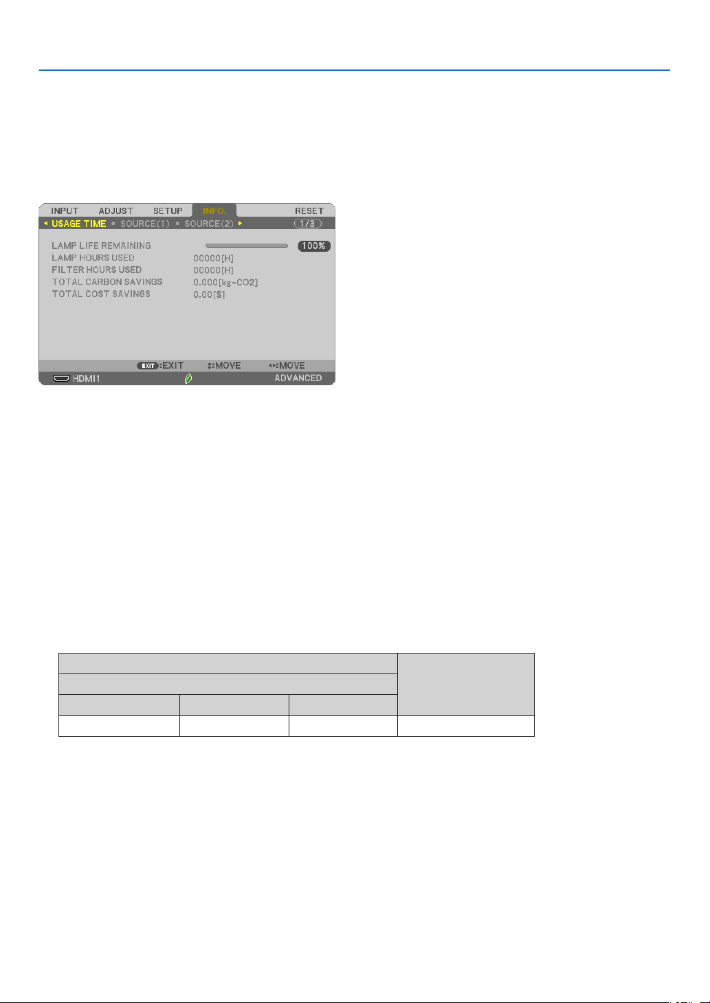
74
5. Using On-Screen Menu
❼ Menu Descriptions & Functions [INFO.]
Displays the status of the current signal and lamp usage. This item has seven pages. The information included is
as follows:
TIP:PressingtheHELPbuttonontheremotecontrolwillshowthe[INFO.]menuitems.
[USAGE TIME]
[LAMP LIFE REMAINING] (%)*
[LAMP HOURS USED] (H)
[FILTER HOURS USED] (H)
[TOTAL CARBON SAVINGS] (kg-CO2)
[TOTAL COST SAVINGS]
* The progress indicator shows the percentage of remaining bulb life.
The value informs you of the amount of lamp usage. When the remaining lamp time reaches 0, the LAMP LIFE
REMAINING bar indicator changes from 0% to 100 Hours and starts counting down.
If the remaining lamp time reaches 0 hours, the projector will not turn on.
•Themessagetotheeffectthatthelamportheltershouldbereplacedwillbedisplayedforoneminutewhen
the projector is turned on and when the POWER button on the projector or the remote control is pressed.
To dismiss this message, press any button on the projector or the remote control.
Lamplife(H)
Replacementlamp
ECOMODE
OFF/AUTOECONORMALECO
10000 12000 15000 NP47LP
*1 This is not a warranty time. Repair or replacement parts may be required before the lamp is replaced.
•[TOTALCARBONSAVINGS]
This displays the estimated carbon saving information in kg. The carbon footprint factor in the carbon saving
calculation is based on the OECD (2008 Edition). (→ page
25)
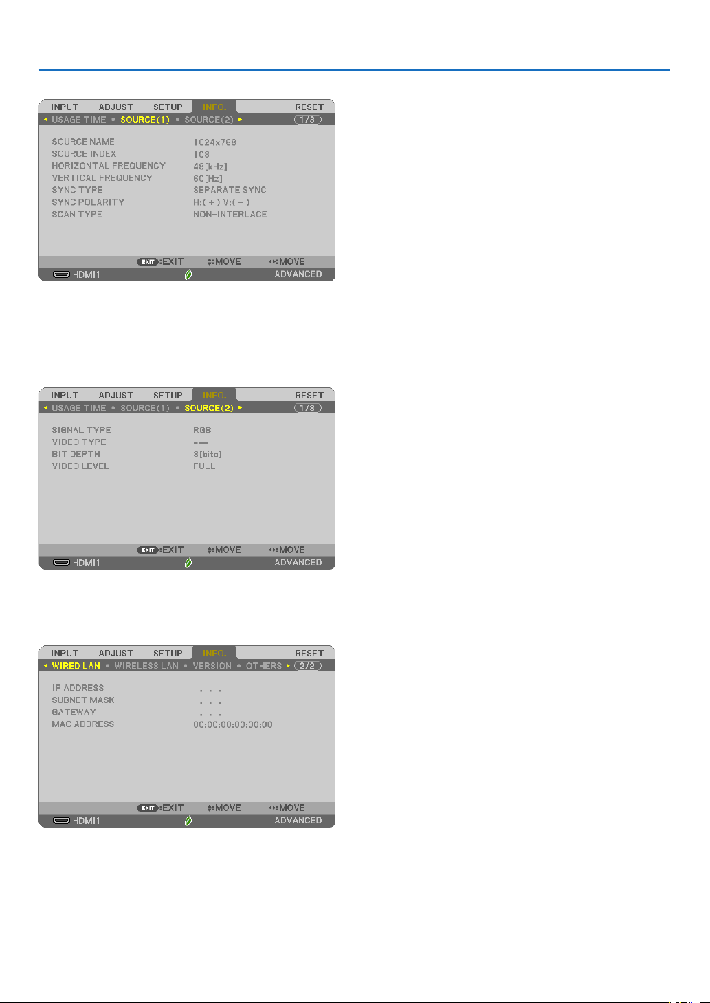
75
5. Using On-Screen Menu
[SOURCE(1)]
[SOURCE NAME] [SOURCE INDEX]
[HORIZONTAL FREQUENCY] [VERTICAL FREQUENCY]
[SYNC TYPE] [SYNC POLARITY]
[SCAN TYPE]
[SOURCE(2)]
[SIGNAL TYPE] [VIDEO TYPE]
[BIT DEPTH] [VIDEO LEVEL]
[WIRED LAN]
[IP ADDRESS] [SUBNET MASK]
[GATEWAY] [MAC ADDRESS]
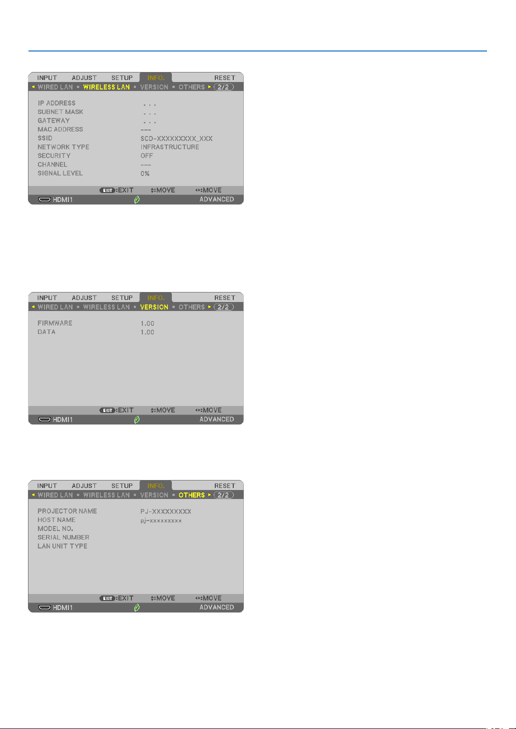
76
5. Using On-Screen Menu
[WIRELESS LAN]
[IP ADDRESS] [SUBNET MASK]
[GATEWAY] [MAC ADDRESS]
[SSID] [NETWORK TYPE]
[SECURITY] [CHANNEL]
[SIGNAL LEVEL]
[VERSION]
[FIRMWARE] Version
[DATA] Version
[OTHERS]
[PROJECTOR NAME]
[HOST NAME]
[MODEL NO.]
[SERIAL NUMBER]
[LAN UNIT TYPE]
[CONTROL ID] (when [CONTROL ID] is set)

77
5. Using On-Screen Menu
❽ Menu Descriptions & Functions [RESET]
Returning to Factory Default [RESET]
The RESET feature allows you to change adjustments and settings to the factory preset for a (all) source (s) except
the following:
[CURRENT SIGNAL]
Resets the adjustments for the current signal to the factory preset levels.
The items that can be reset are: [PRESET], [CONTRAST], [BRIGHTNESS], [COLOR], [HUE], [SHARPNESS],
[ASPECT RATIO], [HORIZONTAL], [VERTICAL], [CLOCK], [PHASE], and [OVERSCAN].
[ALL DATA]
Reset all the adjustments and settings for all the signals to the factory preset.
All items can be reset EXCEPT [LANGUAGE], [BACKGROUND], [ORIENTATION], [FILTER MESSAGE], [STATIC
CONVERGENCE], [ADMINISTRATOR MODE], [SECURITY], [COMMUNICATION SPEED], [CONTROL ID],
[STANDBY MODE], [FAN MODE], [CARBON CONVERT], [CURRENCY], [CURRENCY CONVERT], [LAMP LIFE
REMAINING], [LAMP HOURS USED], [FILTER HOURS USED], [TOTAL CARBON SAVINGS], [WIRED LAN], and
[WIRELESS LAN].
To reset the lamp usage time, see “Clearing Lamp Hour Meter [CLEAR LAMP HOURS]” below.
ClearingLampHourMeter[CLEARLAMPHOURS]
Resets the lamp clock back to zero. Selecting this option displays submenu for a confirmation. Select [YES] and
press the ENTER button.
NOTE:Elapsedtimeofthelampusewillnotbeaffectedevenwhen[RESET]isdonefromthemenu.
NOTE:Theprojectorwillturnoffandgointostandbymodewhenyoucontinuetousetheprojectorforanother100hoursafterthelamphas
reachedtheendofitslife.Inthisconditionyoucannotclearthelamphourmeteronthemenu.Ifthishappens,presstheHELPbuttononthe
remotecontrolfor10secondstoresetthelampclockbacktozero.Dothisonlyafterreplacingthelamp.
ClearingtheFilterUsageHours[CLEARFILTERHOURS]
Resets the filter usage back to zero. Selecting this option displays submenu for a confirmation. Select [YES] and
press the ENTER button.
NOTE:Elapsedtimeofthelterusewillnotbeaffectedevenwhen[RESET]isdonefromthemenu.
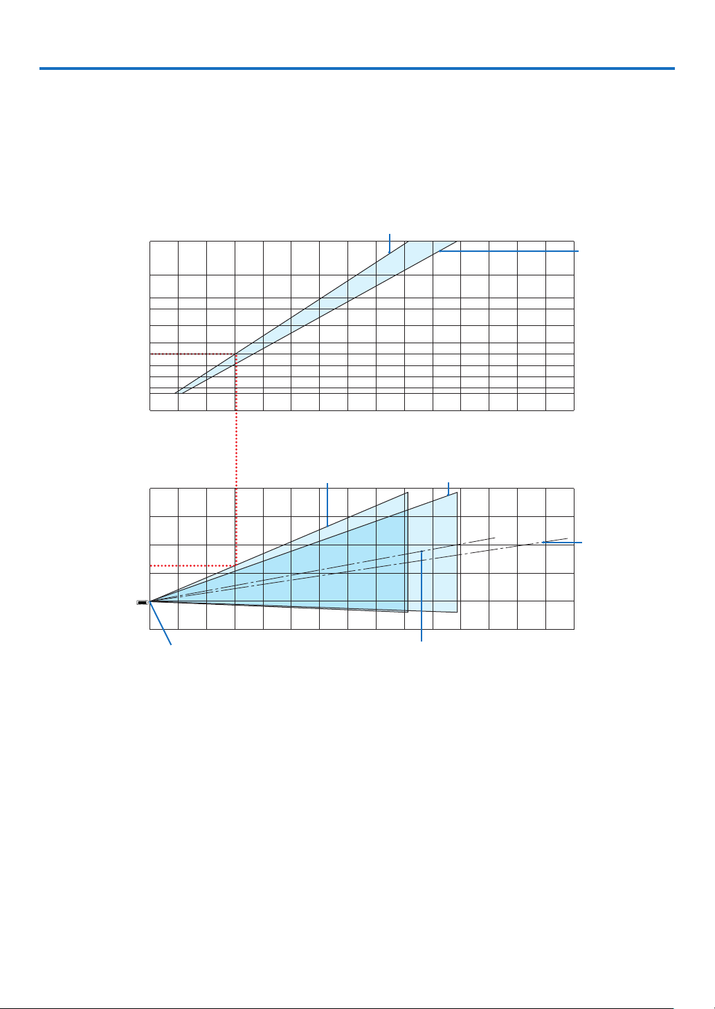
78
6. Installation and Connections
❶ Setting Up the Screen and the Projector
Use this to get a general idea of what the screen size will be when set in a certain position, what size screen you will
need, and what distance you will need to project images of the desired size.
The projection distance range at which focusing is possible is 0.9 m (for 30 inches) to 10.9 m (for 300 inches). Install
within this range.
[MC422X/MC372X]
0123456789 10 11 12 13 14 15
12 13 14 15
-1
1
2
3
4
12345678 91011
40
30
60
80
100
120
150
180
200
240
300
0
(inch)
(m)
Screen size
Screen height from the center of the
projector lens
[Projection distance]
When zoom lever turned to telescopic
Screen center line
(telescopic)
Screen center line (wide)
When zoom lever turned to wide
Projector lens center
(m)
(m)
When zoom lever turned to wide
When zoom lever
turned to telescopic
[Reading the Table]
From the upper table on this page, to project wide images on a 100 screen, install at about 3.0 m from the front.
Also, from the lower table we can see that about 1.3 m are required from the projector’s lens center to the upper
edge of the screen. Use this to see whether or not enough height can be provided from the projector to the ceiling
and for installing the screen. The diagram shows the projection distance when the projector is installed horizontally.
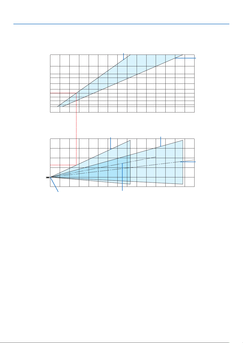
79
6. Installation and Connections
The projection distance range at which focusing is possible is 0.8 m (for 30 inches) to 13.8 m (for 300 inches). Install
within this range.
[ME402X]
0123456789 10 11 12 13 14 15
12 13 14 15
0
1
2
3
4
12345678 91011
40
30
60
80
100
120
150
180
200
240
300
-1
(inch)
(m)
Screen size
Screen height from the center of the
projector lens
[Projection distance]
When zoom lever turned to telescopic
Screen center line
(telescopic)
Screen center line (wide)
When zoom lever turned to wide
Projector lens center
(m)
(m)
When zoom lever turned to wide
When zoom
lever turned to
telescopic
[Reading the Table]
From the upper table on this page, to project wide images on a 100 screen, install at about 2.7 m from the front.
Also, from the lower table we can see that about 1.3 m are required from the projector’s lens center to the upper
edge of the screen. Use this to see whether or not enough height can be provided from the projector to the ceiling
and for installing the screen.
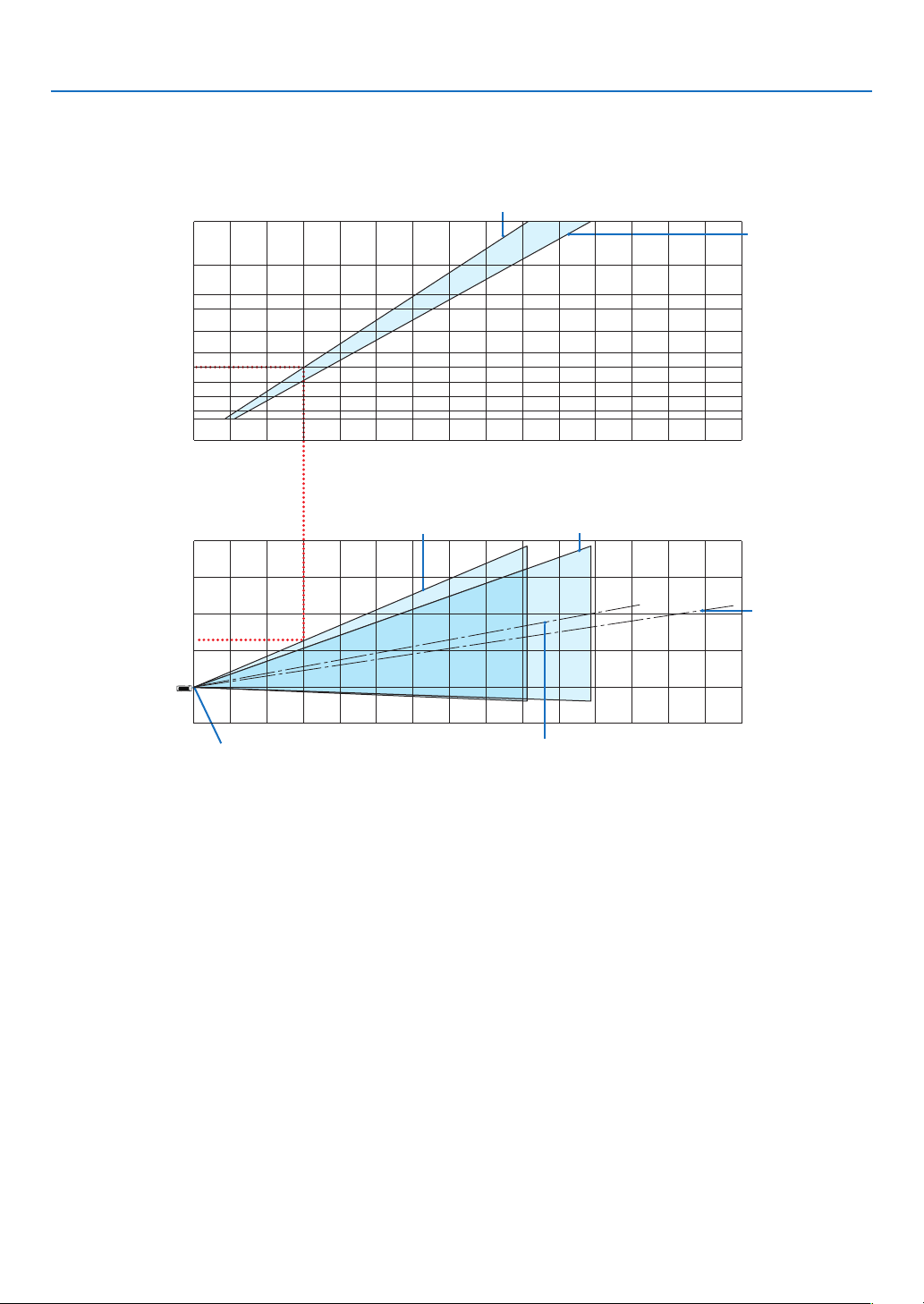
80
6. Installation and Connections
The projection distance range at which focusing is possible is 0.9 m (for 30 inches) to 10.9 m (for 300 inches). Install
within this range.
[MC342X/MC302X]
0123456789 10 11 12 13 14 15
12 13 14 15
-1
1
2
3
4
12345678 91011
40
30
60
80
100
120
150
180
200
240
300
0
(inch)
(m)
Screen size
Screen height from the center of the
projector lens
[Projection distance]
When zoom lever turned to telescopic
Screen center line
(telescopic)
Screen center line (wide)
When zoom lever turned to wide
Projector lens center
(m)
(m)
When zoom lever turned to wide
When zoom lever
turned to telescopic
[Reading the Table]
From the upper table on this page, to project wide images on a 100 screen, install at about 3.0 m from the front.
Also, from the lower table we can see that about 1.3 m are required from the projector’s lens center to the upper
edge of the screen. Use this to see whether or not enough height can be provided from the projector to the ceiling
and for installing the screen. The diagram shows the projection distance when the projector is installed horizontally.
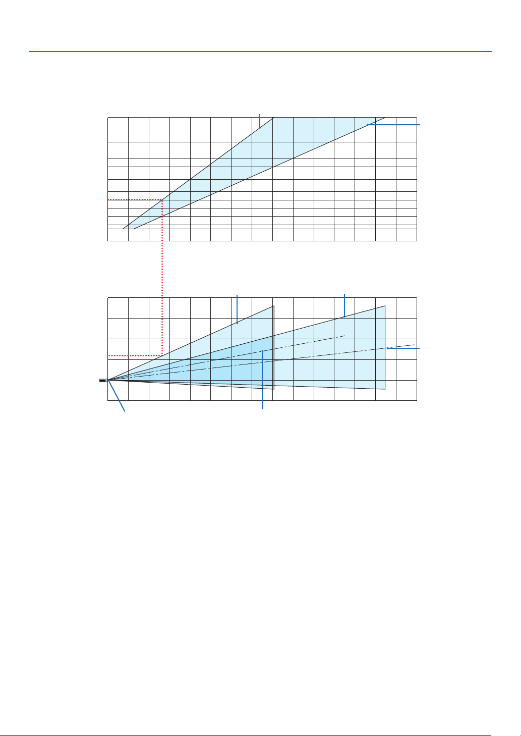
81
6. Installation and Connections
The projection distance range at which focusing is possible is 0.8 m (for 30 inches) to 13.4 m (for 300 inches). Install
within this range.
[ME372W]
012345678910 11 12 13 14 15
12 13 14 15
0
1
2
3
4
1234567891011
40
30
60
80
100
120
150
180
200
240
300
-1
(inch)
(m)
Screen size
Screen height from the center of the
projector lens
[Projection distance]
When zoom lever turned to telescopic
Screen center line
(telescopic)
Screen center line (wide)
When zoom lever turned to wide
Projector lens center
(m)
(m)
When zoom lever turned to wide
When zoom
lever turned to
telescopic
[Reading the Table]
From the upper table on this page, to project wide images on a 100 screen, install at about 2.7 m from the front.
Also, from the lower table we can see that about 1.2 m are required from the projector’s lens center to the upper
edge of the screen. Use this to see whether or not enough height can be provided from the projector to the ceiling
and for installing the screen.
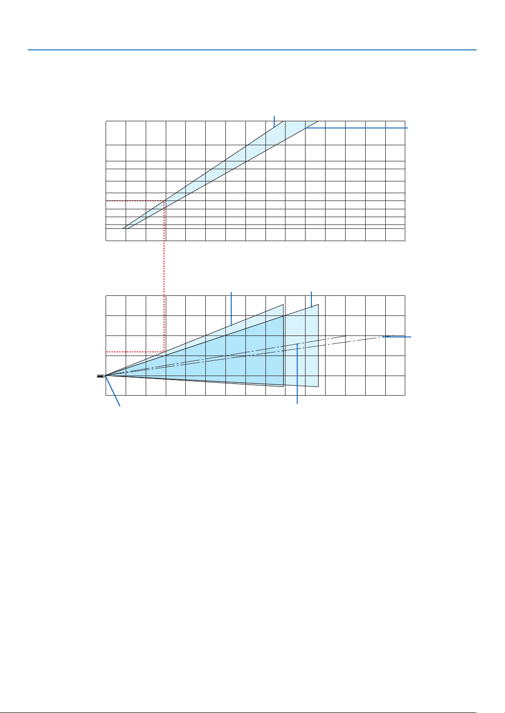
82
6. Installation and Connections
The projection distance range at which focusing is possible is 0.9 m (for 30 inches) to 10.7 m (for 300 inches). Install
within this range.
[MC382W]
0123456789 10 11 12 13 14 15
12 13 14 15
-1
1
2
3
4
12345678 91011
40
30
60
80
100
120
150
180
200
240
300
0
(inch)
(m)
Screen size
Screen height from the center of the
projector lens
[Projection distance]
When zoom lever turned to telescopic
Screen center line
(telescopic)
Screen center line (wide)
When zoom lever turned to wide
Projector lens center
(m)
(m)
When zoom lever turned to wide
When zoom lever
turned to telescopic
[Reading the Table]
From the upper table on this page, to project wide images on a 100 screen, install at about 3.0 m from the front.
Also, from the lower table we can see that about 1.2 m are required from the projector’s lens center to the upper
edge of the screen. Use this to see whether or not enough height can be provided from the projector to the ceiling
and for installing the screen. The diagram shows the projection distance when the projector is installed horizontally.
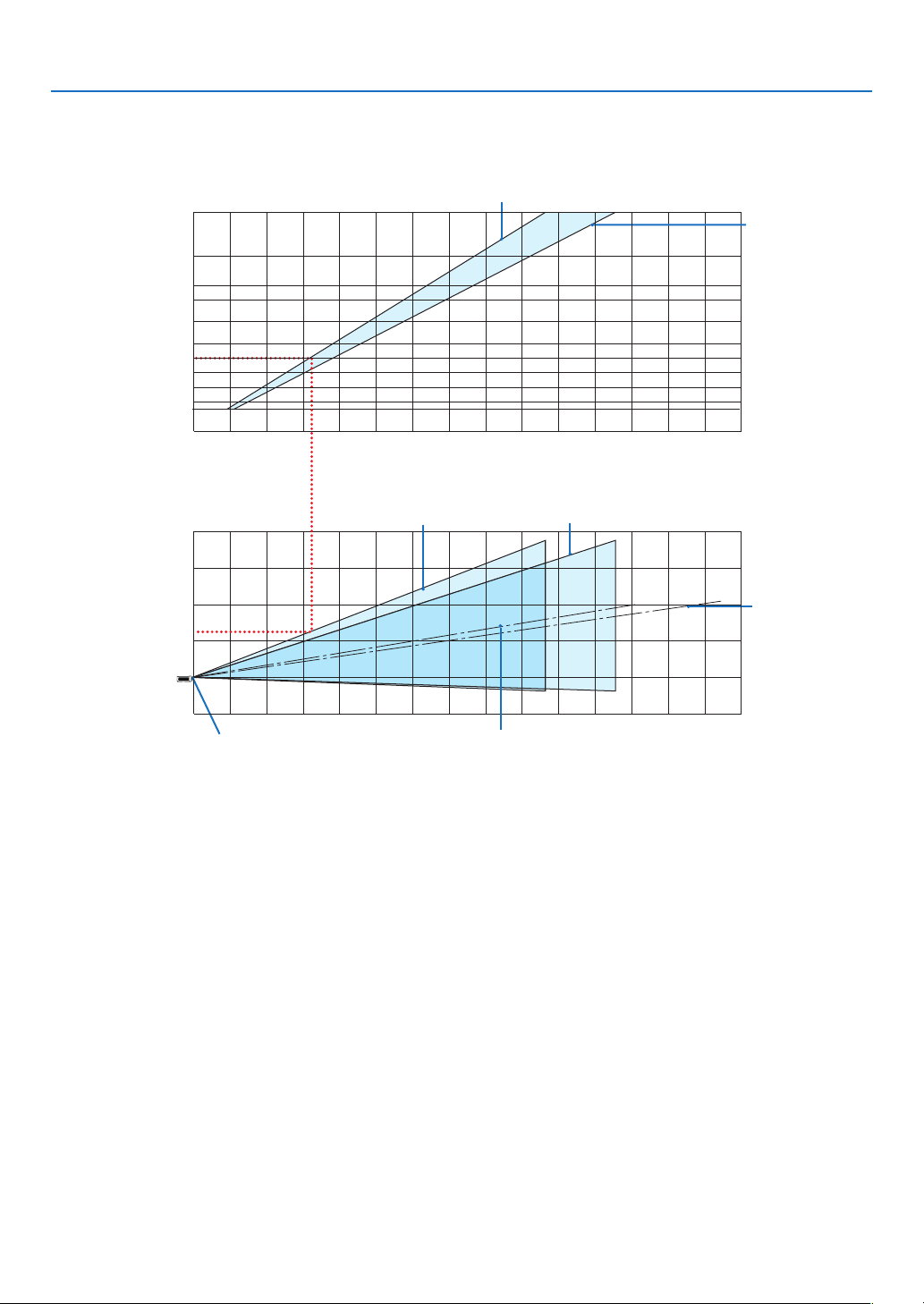
83
6. Installation and Connections
The projection distance range at which focusing is possible is 1.0 m (for 30 inches) to 11.6 m (for 300 inches). Install
within this range.
[MC332W]
012345678910 11 12 13 14 15
12 13 14 15
-1
1
2
3
4
1234567891011
40
30
60
80
100
120
150
180
200
240
300
0
(inch)
(m)
Screen size
Screen height from the center of the
projector lens
[Projection distance]
When zoom lever turned to telescopic
Screen center line
(telescopic)
Screen center line (wide)
When zoom lever turned to wide
Projector lens center
(m)
(m)
When zoom lever turned to wide
When zoom lever
turned to telescopic
[Reading the Table]
From the upper table on this page, to project wide images on a 100 screen, install at about 3.2 m from the front.
Also, from the lower table we can see that about 1.3 m are required from the projector’s lens center to the upper
edge of the screen. Use this to see whether or not enough height can be provided from the projector to the ceiling
and for installing the screen. The diagram shows the projection distance when the projector is installed horizontally.
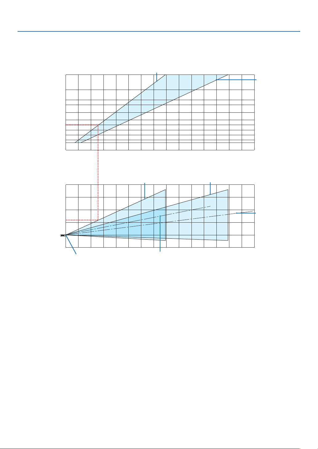
84
6. Installation and Connections
The projection distance range at which focusing is possible is 0.8 m (for 30 inches) to 12.9 m (for 300 inches). Install
within this range.
[ME382U/ME342U]
012345678910 11 12 13 14 15
12 13 14 15
0
1
2
3
4
1234567891011
40
30
60
80
100
120
150
180
200
240
300
-1
(inch)
(m)
Screen size
Screen height from the center of the
projector lens
[Projection distance]
When zoom lever turned to telescopic
Screen center line
(telescopic)
Screen center line (wide)
When zoom lever turned to wide
Projector lens center
(m)
(m)
When zoom lever turned to wide
When zoom lever
turned to telescopic
[Reading the Table]
From the upper table on this page, to project wide images on a 100 screen, install at about 2.6 m from the front.
Also, from the lower table we can see that about 1.2 m are required from the projector’s lens center to the upper
edge of the screen. Use this to see whether or not enough height can be provided from the projector to the ceiling
and for installing the screen.
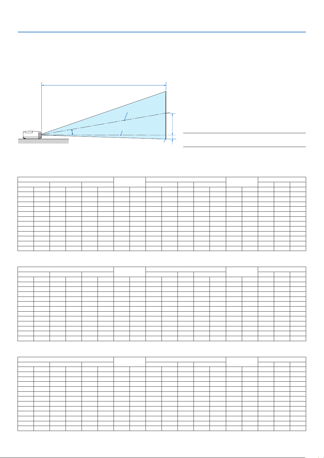
85
6. Installation and Connections
C
α
B
D
Throw Distance and Screen Size
The following shows the proper relative positions of the projector and screen. Refer to the table to determine the
position of installation.
DistanceChart
B = Vertical distance between lens center and
screen center
C = Throw distance
D = Vertical distance between lens center and
screen bottom (top of screen for ceiling
application)
α = Throw angle
NOTE:Thevaluesinthetablesaredesignvaluesandmay
vary.
[MC422X/MC372X]
Screen Size
B
C
D
α
Diagonal Width Height Wide Tele Wide Tele
inch mm inch mm inch mm inch mm inch mm - inch mm inch mm Degree - Degree
30 762 24 610 18 457 6 163 35 900 - 43 1083 -3 -65 10�3 - 8�6
40 1016 32 813 24 610 9 218 47 1204 - 57 1448 -3 -87 10�3 - 8�6
60 1524 48 1219 36 914 13 327 71 1812 - 86 2179 -5 -130 10�2 - 8�5
80 2032 64 1626 48 1219 17 436 95 2421 - 115 2910 -7 -174 10�2 - 8�5
100 2540 80 2032 60 1524 21 545 119 3029 - 143 3641 -9 -217 10�2 - 8�5
120 3048 96 2438 72 1829 26 653 143 3637 - 172 4372 -10 -261 10�2 - 8�5
150 3810 120 3048 90 2286 32 817 179 4550 - 215 5468 -13 -326 10�2 - 8�5
180 4572 144 3658 108 2743 39 980 215 5462 - 258 6564 -15 -391 10�2 - 8�5
200 5080 160 4064 120 3048 43 1089 239 6070 - 287 7295 -17 -435 10�2 - 8�5
240 6096 192 4877 144 3658 51 1307 287 7287 - 345 8756 -21 -522 10�2 - 8�5
270 6858 216 5486 162 4115 58 1470 323 8199 - 388 9853 -23 -587 10�2 - 8�5
300 7620 240 6096 180 4572 64 1634 359 9112 - 431 10949 -26 -652 10�2 - 8�5
[ME402X]
Screen Size
B
C
D
α
Diagonal Width Height Wide Tele Wide Tele
inch mm inch mm inch mm inch mm inch mm - inch mm inch mm Degree - Degree
30 762 24 610 18 457 6 157 31 778 - 52 1327 -3 -71 11�4 - 6�8
40 1016 32 813 24 610 8 210 42 1056 - 70 1788 -4 -95 11�2 - 6�7
60 1524 48 1219 36 914 12 314 63 1612 - 107 2710 -6 -143 11�0 - 6�6
80 2032 64 1626 48 1219 17 419 85 2168 - 143 3632 -8 -191 10�9 - 6�6
100 2540 80 2032 60 1524 21 524 107 2724 - 179 4554 -9 -238 10�9 - 6�6
120 3048 96 2438 72 1829 25 629 129 3280 - 216 5476 -11 -286 10�8 - 6�5
150 3810 120 3048 90 2286 31 786 162 4114 - 270 6859 -14 -357 10�8 - 6�5
180 4572 144 3658 108 2743 37 943 195 4948 - 324 8242 -17 -429 10�8 - 6�5
200 5080 160 4064 120 3048 41 1048 217 5504 - 361 9164 -19 -476 10�8 - 6�5
240 6096 192 4877 144 3658 50 1257 260 6616 - 433 11008 -23 -572 10�8 - 6�5
270 6858 216 5486 162 4115 56 1414 293 7450 - 488 12391 -25 -643 10�8 - 6�5
300 7620 240 6096 180 4572 62 1572 326 8284 - 542 13774 -28 -714 10�7 - 6�5
[MC342X/MC302X]
Screen Size
B
C
D
α
Diagonal Width Height Wide Tele Wide Tele
inch mm inch mm inch mm inch mm inch mm - inch mm inch mm Degree - Degree
30 762 24 610 18 457 6 163 34 876 - 42 1058 -3 -65 10�6 - 8�8
40 1016 32 813 24 610 9 218 46 1180 - 56 1422 -3 -87 10�5 - 8�7
60 1524 48 1219 36 914 13 327 70 1786 - 85 2150 -5 -130 10�4 - 8�6
80 2032 64 1626 48 1219 17 436 94 2393 - 113 2879 -7 -174 10�3 - 8�6
100 2540 80 2032 60 1524 21 545 118 3000 - 142 3607 -9 -217 10�3 - 8�6
120 3048 96 2438 72 1829 26 653 142 3606 - 171 4335 -10 -261 10�3 - 8�6
150 3810 120 3048 90 2286 32 817 178 4517 - 214 5427 -13 -326 10�2 - 8�6
180 4572 144 3658 108 2743 39 980 214 5427 - 257 6520 -15 -391 10�2 - 8�5
200 5080 160 4064 120 3048 43 1089 238 6033 - 285 7248 -17 -435 10�2 - 8�5
240 6096 192 4877 144 3658 51 1307 285 7247 - 343 8704 -21 -522 10�2 - 8�5
270 6858 216 5486 162 4115 58 1470 321 8157 - 386 9797 -23 -587 10�2 - 8�5
300 7620 240 6096 180 4572 64 1634 357 9067 - 429 10889 -26 -652 10�2 - 8�5
Screen center
Lens center
Screen bottom
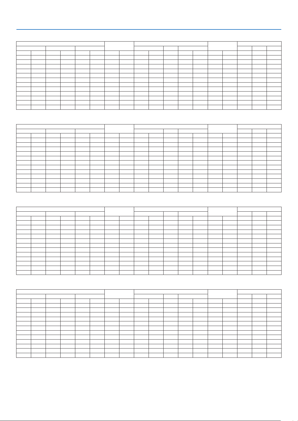
86
6. Installation and Connections
[ME372W]
Screen Size
B
C
D
α
Diagonal Width Height Wide Tele Wide Tele
inch mm inch mm inch mm inch mm inch mm - inch mm inch mm Degree - Degree
30 762 25 646 16 404 6 154 30 755 - 51 1291 -2 -48 11�5 - 6�8
40 1016 34 862 21 538 8 206 40 1025 - 69 1740 -3 -64 11�3 - 6�7
60 1524 51 1292 32 808 12 309 62 1565 - 104 2638 -4 -95 11�2 - 6�7
80 2032 68 1723 42 1077 16 411 83 2105 - 139 3536 -5 -127 11�1 - 6�6
100 2540 85 2154 53 1346 20 514 104 2645 - 175 4434 -6 -159 11�0 - 6�6
120 3048 102 2585 64 1615 24 617 125 3186 - 210 5332 -8 -191 11�0 - 6�6
150 3810 127 3231 79 2019 30 771 157 3996 - 263 6679 -9 -238 10�9 - 6�6
180 4572 153 3877 95 2423 36 926 189 4806 - 316 8025 -11 -286 10�9 - 6�6
200 5080 170 4308 106 2692 40 1028 210 5346 - 351 8923 -13 -318 10�9 - 6�6
240 6096 204 5169 127 3231 49 1234 253 6427 - 422 10719 -15 -381 10�9 - 6�6
270 6858 229 5816 143 3635 55 1388 285 7237 - 475 12066 -17 -429 10�9 - 6�6
300 7620 254 6462 159 4039 61 1543 317 8048 - 528 13413 -19 -477 10�8 - 6�6
[MC382W]
Screen Size
B
C
D
α
Diagonal Width Height Wide Tele Wide Tele
inch mm inch mm inch mm inch mm inch mm - inch mm inch mm Degree - Degree
30 762 25 646 16 404 6 160 34 856 - 41 1046 -2 -42 10�6 - 8�7
40 1016 34 862 21 538 8 214 45 1153 - 55 1403 -2 -55 10�5 - 8�7
60 1524 51 1292 32 808 13 321 69 1748 - 83 2117 -3 -83 10�4 - 8�6
80 2032 68 1723 42 1077 17 428 92 2342 - 111 2831 -4 -111 10�3 - 8�6
100 2540 85 2154 53 1346 21 534 116 2937 - 140 3545 -5 -139 10�3 - 8�6
120 3048 102 2585 64 1615 25 641 139 3531 - 168 4260 -7 -166 10�3 - 8�6
150 3810 127 3231 79 2019 32 802 174 4423 - 210 5331 -8 -208 10�3 - 8�6
180 4572 153 3877 95 2423 38 962 209 5314 - 252 6402 -10 -250 10�3 - 8�5
200 5080 170 4308 106 2692 42 1069 233 5909 - 280 7116 -11 -277 10�3 - 8�5
240 6096 204 5169 127 3231 50 1283 279 7097 - 336 8544 -13 -333 10�2 - 8�5
270 6858 229 5816 143 3635 57 1443 315 7989 - 379 9615 -15 -374 10�2 - 8�5
300 7620 254 6462 159 4039 63 1603 350 8881 - 421 10686 -16 -416 10�2 - 8�5
[MC332W]
Screen Size
B
C
D
α
Diagonal Width Height Wide Tele Wide Tele
inch mm inch mm inch mm inch mm inch mm - inch mm inch mm Degree - Degree
30 762 25 635 16 406 7 174 38 955 - 45 1149 -1 -29 10�3 - 8�6
40 1016 34 864 21 533 9 229 50 1277 - 60 1536 -2 -38 10�2 - 8�5
60 1524 51 1295 32 813 14 348 76 1922 - 91 2311 -2 -58 10�2 - 8�5
80 2032 68 1727 42 1067 18 457 101 2567 - 121 3086 -3 -77 10�2 - 8�5
100 2540 85 2159 53 1346 23 577 126 3211 - 152 3860 -4 -96 10�2 - 8�5
120 3048 102 2591 64 1626 27 697 152 3856 - 182 4635 -5 -115 10�2 - 8�5
150 3810 127 3226 79 2007 34 860 190 4823 - 228 5797 -6 -144 10�2 - 8�5
180 4572 153 3886 95 2413 41 1035 228 5790 - 274 6959 -7 -173 10�2 - 8�5
200 5080 170 4318 106 2692 45 1154 253 6435 - 304 7733 -8 -192 10�2 - 8�5
240 6096 204 5182 127 3226 54 1383 304 7725 - 365 9283 -9 -230 10�2 - 8�5
270 6858 229 5817 143 3632 61 1557 342 8692 - 411 10445 -10 -259 10�2 - 8�5
300 7620 254 6452 159 4039 68 1732 380 9659 - 457 11607 -11 -288 10�2 - 8�5
[ME382U/ME342U]
Screen Size
B
C
D
α
Diagonal Width Height Wide Tele Wide Tele
inch mm inch mm inch mm inch mm inch mm - inch mm inch mm Degree - Degree
30 762 25 646 16 404 6 154 29 745 - 49 1240 -2 -48 11�7 - 7�1
40 1016 34 862 21 538 8 206 40 1012 - 66 1670 -3 -64 11�5 - 7�0
60 1524 51 1292 32 808 12 309 61 1545 - 100 2532 -4 -95 11�3 - 6�9
80 2032 68 1723 42 1077 16 411 82 2079 - 134 3393 -5 -127 11�2 - 6�9
100 2540 85 2154 53 1346 20 514 103 2612 - 167 4254 -6 -159 11�1 - 6�9
120 3048 102 2585 64 1615 24 617 124 3145 - 201 5115 -8 -191 11�1 - 6�9
150 3810 127 3231 79 2019 30 771 155 3945 - 252 6407 -9 -238 11�1 - 6�9
180 4572 153 3877 95 2423 36 926 187 4745 - 303 7699 -11 -286 11�0 - 6�9
200 5080 170 4308 106 2692 40 1028 208 5278 - 337 8560 -13 -318 11�0 - 6�9
240 6096 204 5169 127 3231 49 1234 250 6345 - 405 10283 -15 -381 11�0 - 6�8
270 6858 229 5816 143 3635 55 1388 281 7145 - 456 11575 -17 -429 11�0 - 6�8
300 7620 254 6462 159 4039 61 1543 313 7945 - 507 12867 -19 -477 11�0 - 6�8

87
6. Installation and Connections
WARNING
•Installingyourprojectorontheceilingmustbedonebyaqualiedtechnician.ContactyourNECdealerformore
information.
•Donotattempttoinstalltheprojectoryourself.
•Onlyuseyourprojectoronasolid,levelsurface.Iftheprojectorfallstotheground,youcanbeinjuredandthe
projector severely damaged.
•Donotusetheprojectorwheretemperaturesvarygreatly.Theprojectormustbeusedattemperaturesbetween
41°F(5°C)and104°F(40°C)(Ecomodeselectedautomaticallyat95°Fto104°F/35°Cto40°C).
•Donotexposetheprojectortomoisture,dust,orsmoke.Thiswillharmthescreenimage.
•Ensurethatyouhaveadequateventilationaroundyourprojectorsoheatcandissipate.Donotcovertheventson
the side or the front of the projector.
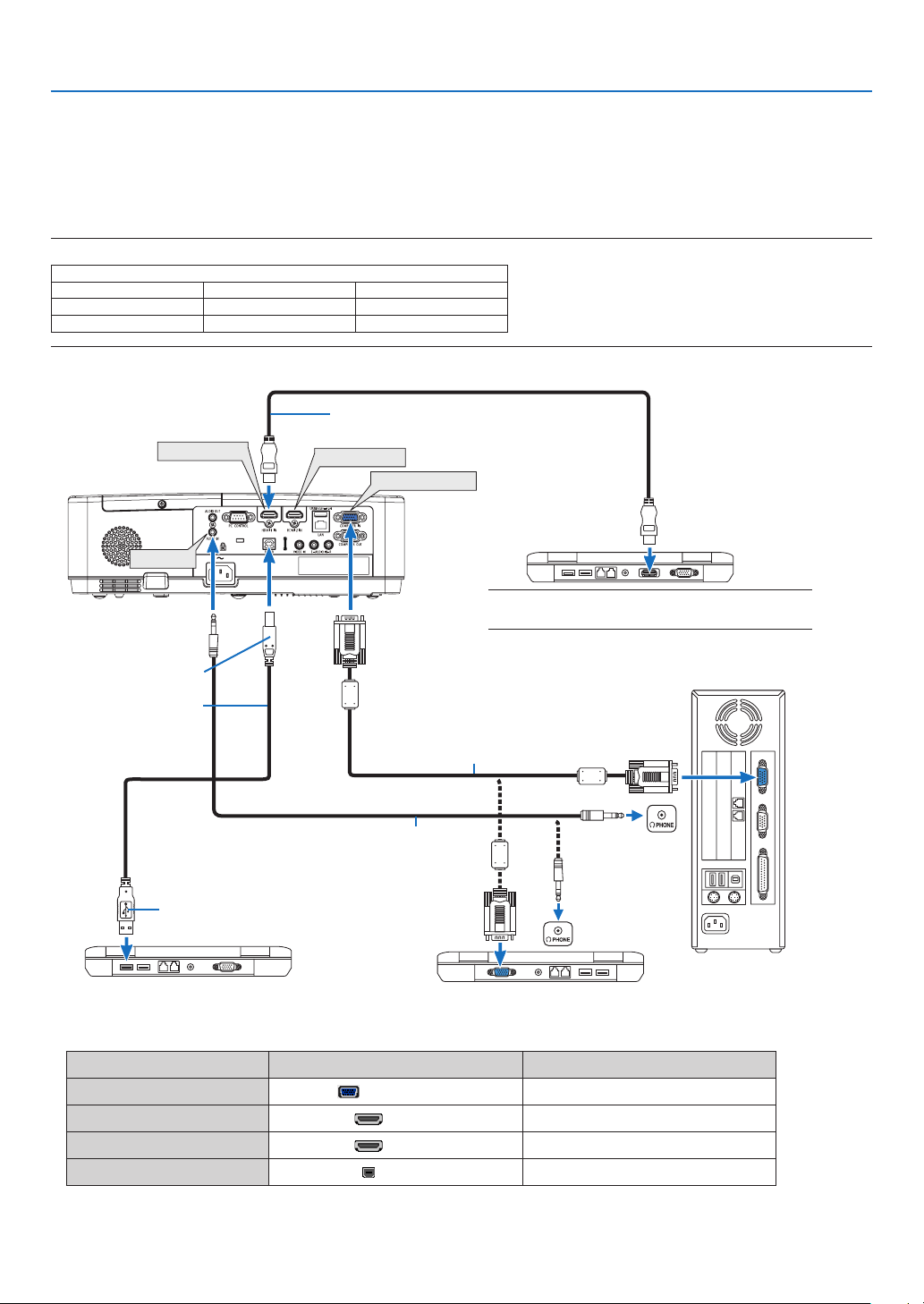
88
6. Installation and Connections
❷ Making Connections
Connecting Your Computer
Computer cables, HDMI and USB can be used to connect to a computer. The connection cable is not enclosed with
the projector. Please get ready a suitable cable for the connection.
NOTE:SignalssupportedbyPlug&Play(DDC2)
INPUT
COMPUTER IN HDMI 1 IN HDMI 2 IN
analog digital digital
Yes Yes Yes
•Selectthesourcenameforitsappropriateinputterminalafterturningontheprojector.
Input terminal
INPUT button on the projector cabinet
Button on the remote control
COMPUTER IN
COMPUTER
(COMPUTER)
HDMI 1 IN
HDMI1 (HDMI 1)
HDMI 2 IN
HDMI2 (HDMI 2)
USB-B
USB-B (USB-B)
HDMI 1 IN
HDMI 2 IN
COMPUTER IN
AUDIO IN
A commercially avail-
able USB cable
(compatible with USB
2.0 specifications)
Computer cable (VGA) (supplied)
To mini D-Sub 15-pin terminal on the
projector.Itisrecommendedthatyouusea
commercially available distribution amplifier
ifconnectingasignalcablelongerthanthe
cable supplied.
Type B
Type A
Stereo mini-plug audio cable (not supplied)
HDMIcable(notsupplied)
UseHighSpeedHDMI
®
Cable.
NOTE:ForMac,useacommerciallyavailablepinadapter
(notsupplied)toconnecttoyourMac’svideoport.
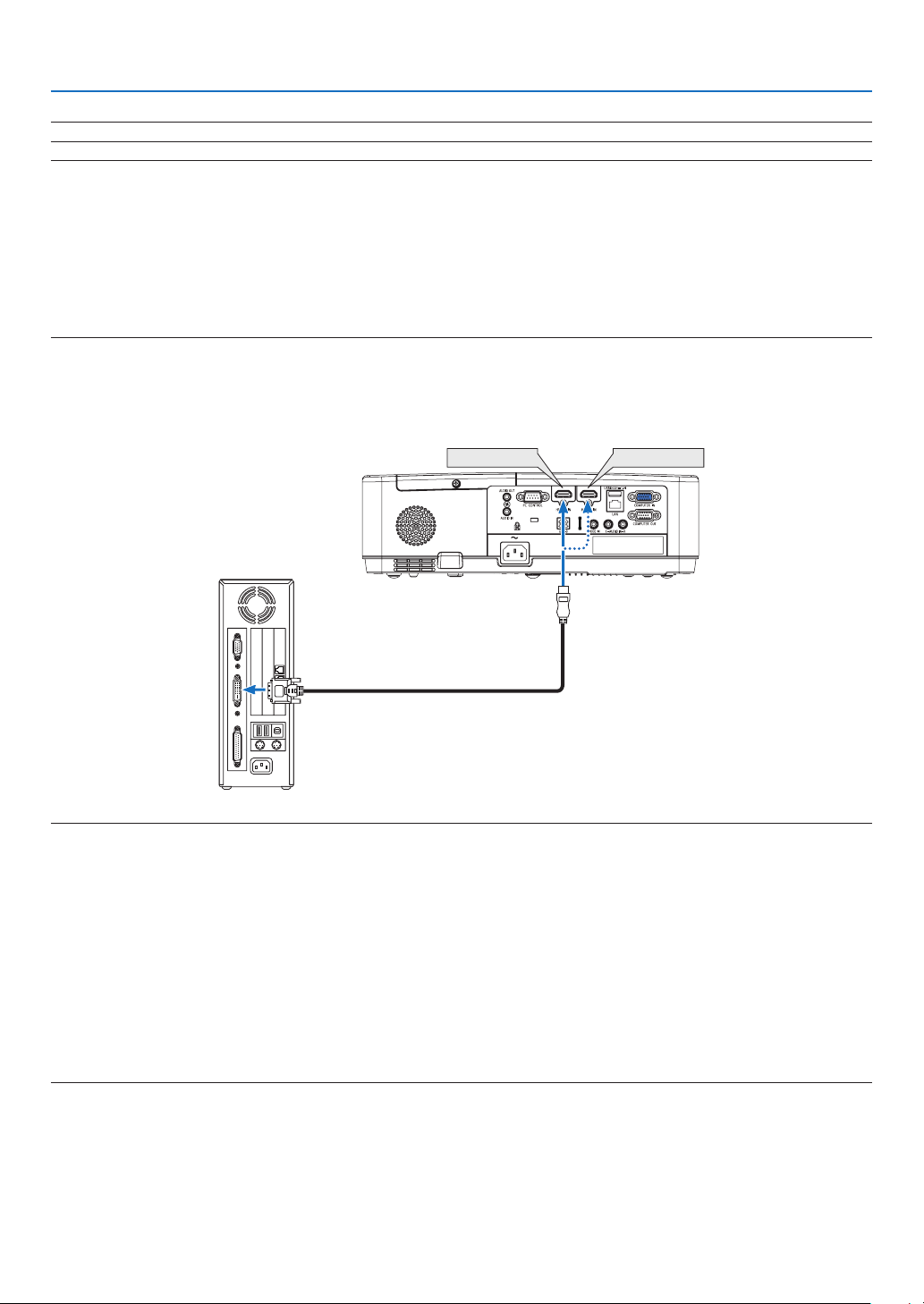
89
6. Installation and Connections
NOTE:TheprojectorisnotcompatiblewithvideodecodedoutputsoftheNECISS-6020switcher.
NOTE:AnimagemaynotbedisplayedcorrectlywhenaVideosourceisplayedbackviaacommerciallyavailablescanconverter.
Thisisbecausetheprojectorwillprocessavideosignalasacomputersignalatthedefaultsetting.Inthatcase,dothefollowing.
*Whenanimageisdisplayedwiththelowerandupperblackportionofthescreenoradarkimageisnotdisplayedcorrectly:
ProjectanimagetollthescreenandthenpresstheAUTOADJ.buttonontheremotecontrolortheprojectorcabinet.
Enabling the computer’s external display
DisplayinganimageonthenotebookPC’sscreendoesnotnecessarilymeanitoutputsasignaltotheprojector.
WhenusingaPCcompatiblelaptop,acombinationoffunctionkeyswillenable/disabletheexternaldisplay.
Usually,thecombinationofthe“Fn”keyalongwithoneofthe12functionkeysgetstheexternaldisplaytocomeonoroff.Forexample,NEC
laptopsuseFn+F3,whileDelllaptopsuseFn+F8keycombinationstotogglethroughexternaldisplayselections.
CautionswhenusingaDVIsignal
•WhenthecomputerhasaDVIoutputterminal,useacommerciallyavailableconvertercabletoconnectthecom-
puter to the projector’s HDMI 1 or HDMI 2 input terminal (only digital video signals can be input).
HDMI 1 IN HDMI 2 IN
NOTE:WhenViewingaDVIDigitalSignal
•Turnoffthepowerofthecomputerandprojectorbeforeconnecting.
•Whenavideodeckisconnectedviaascanconverter,etc.,thedisplaymaynotbecorrectduringfast-forwardingandrewinding.
•UseaDVI-to-HDMIcablecompliantwithDDWG(DigitalDisplayWorkingGroup)DVI(DigitalVisualInterface)revision1.0standard.
Thecableshouldbewithin197"/5mlong.
•TurnofftheprojectorandthePCbeforeconnectingtheDVI-to-HDMIcable.
•ToprojectaDVIdigitalsignal:Connectthecables,turntheprojectoron,thenselecttheHDMIinput.Finally,turnonyourPC.
Failuretodosomaynotactivatethedigitaloutputofthegraphicscardresultinginnopicturebeingdisplayed.Shouldthishappen,restart
yourPC.
•DonotdisconnecttheDVI-to-HDMIcablewhiletheprojectorisrunning.Ifthesignalcablehasbeendisconnectedandthenreconnected,
animagemaynotbecorrectlydisplayed.Shouldthishappen,restartyourPC.
•TheCOMPUTERvideoinputterminalssupportWindowsPlugandPlay.
•AMacsignaladapter(commerciallyavailable)mayberequiredtoconnectaMaccomputer.
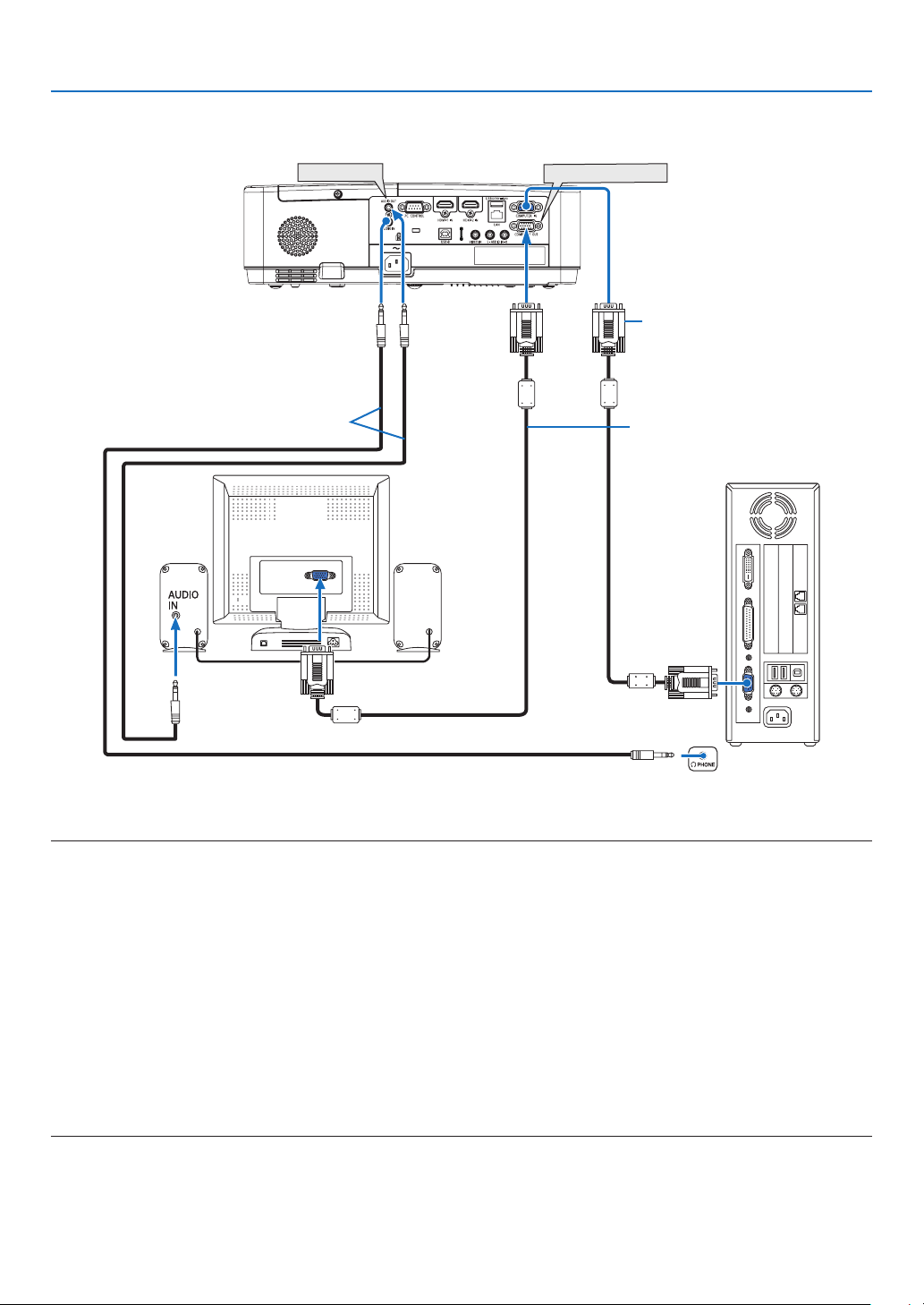
90
6. Installation and Connections
Connecting an External Monitor
You can connect a separate, external monitor to your projector to simultaneously view on a monitor the computer
analog image you’re projecting.
NOTE:
•TheAUDIOOUTminijackdoesnotsupportearphone/headphoneterminal.
•Whenaudioequipmentisconnected,theprojectorspeakerisdisabled.
•ThesignaloutputfromtheCOMPUTEROUTofthisprojectorisforprojectingimageonexclusiveonedisplay.
•Whennosignalisappliedover3minutesintheconditionofprojectorstandbywhenNETWORKSTANDBYissetintheStandbymode,
outputfromtheCOMPUTEROUTorAUDIOOUTterminalwillbestopped.Inthiscase,pulloutthecomputercableandsetitbackafter
inputtingvideosignal.
Monitoroutandsleepmode:
•TheCOMPUTEROUTterminalwillnotworkwhen[NORMAL]isselectedfor[STANDBYMODE].
TheCOMPUTEROUTterminalwillworkonlyinthesleepmode.
ApplyingasignalfromtheCOMPUTERINterminalwillputtheprojectorinthesleepmode,whichallowsyoutousetheCOMPUTEROUT
terminal and the AUDIO OUT mini jack.
Thesleepmodeisoneofthestandbymodes.
•Inthenetworkstandbymode,soundforthelastviewedcomputerorvideosourcewillbeheard.
BNC-to-COMPUTERINterminalconvertedsignalwillnotbeoutputinthestandbymodeandsleepmode.
AUDIO OUT
COMPUTER OUT
Computer cable (VGA) (supplied)
Computer cable (VGA) (not supplied)
Stereo mini-plug audio cable (not supplied)
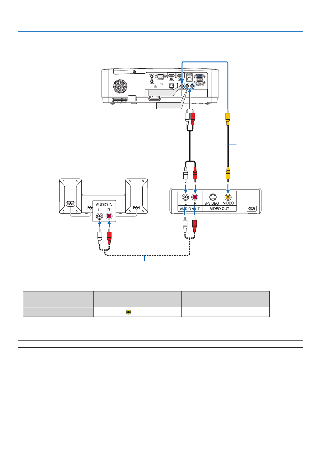
91
6. Installation and Connections
Connecting Your DVD Player or Other AV Equipment
Connecting Video Input
AUDIO IN
VIDEO IN
Video cable (not supplied)
Audio cable (not supplied)
Audio cable (not supplied)
Audio equipment
•Selectthesourcenameforitsappropriateinputterminalafterturningontheprojector.
Input terminal
INPUT button on the projector
cabinet
Button on the remote control
VIDEO IN
VIDEO
(VIDEO)
NOTE:RefertoyourVCRowner’smanualformoreinformationaboutyourequipment’svideooutputrequirements.
NOTE:AnimagemaynotbedisplayedcorrectlywhenaVideosourceisplayedbackinfast-forwardorfast-rewindviaascanconverter.
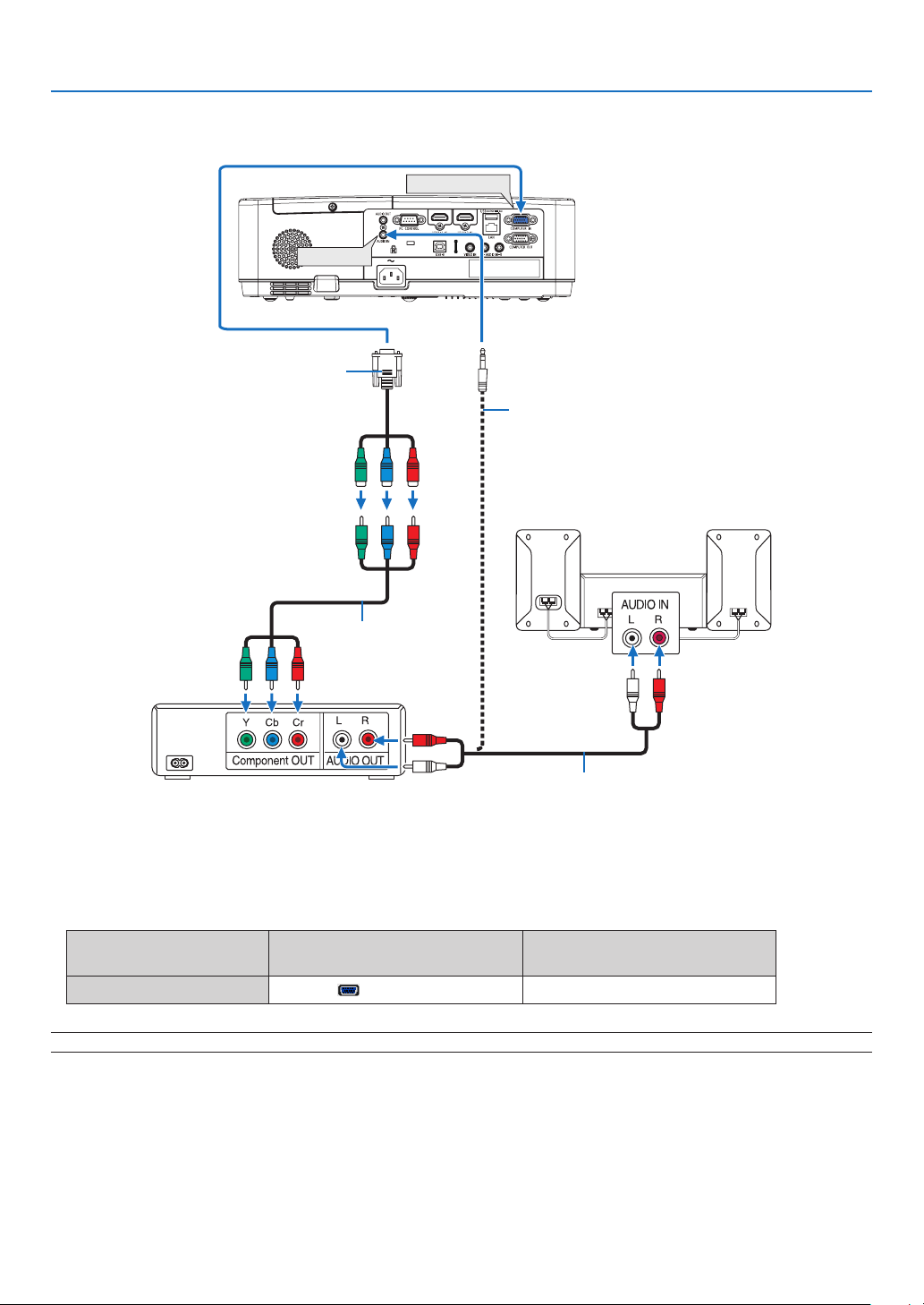
92
6. Installation and Connections
Connecting Component Input
COMPUTER IN
AUDIO IN
15-pin-to-RCA(female)×3cableadapter
(ADP-CV1E)
Stereo mini plug - to - RCA audio cable (not supplied)
Component video RCA ×
3 cable (not supplied)
Audio cable (not supplied)
DVD player
Audio Equipment
A component signal will be automatically displayed. If not, from the menu, select [SETUP] → [OPTIONS(1)] →
[SIGNAL SELECT] → [COMPUTER], and then place a check mark in the Component radio button.
•Selectthesourcenameforitsappropriateinputterminalafterturningontheprojector.
Input terminal
INPUT button on the projector
cabinet
Button on the remote control
COMPUTER IN
COMPUTER
(COMPUTER)
NOTE:RefertoyourDVDplayer’sowner’smanualformoreinformationaboutyourDVDplayer’svideooutputrequirements.
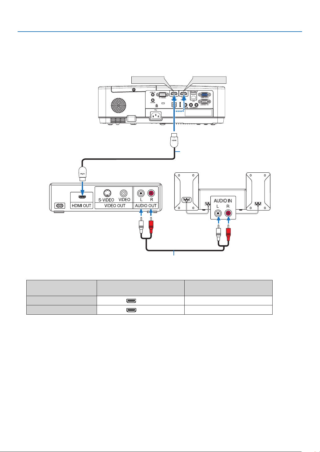
93
6. Installation and Connections
Connecting HDMI Input
You can connect the HDMI output of your DVD player, hard disk player, Blu-ray player, or notebook type PC to the
HDMI IN terminal of your projector.
•Selectthesourcenameforitsappropriateinputterminalafterturningontheprojector.
Input terminal
INPUT button on the projector
cabinet
Button on the remote control
HDMI 1 IN
HDMI1 (HDMI1)
HDMI 2 IN
HDMI2 (HDMI2)
•WhenconnectingtheHDMI1INterminal(orHDMI2terminal)oftheprojectortotheDVDplayer,theprojector’s
video level can be made settings in accordance with the DVD player’s video level. In the menu select [SETUP]
→ [OPTIONS(1)] → [VIDEO LEVEL] and make necessary settings.
HDMI 1 IN
HDMI 2 IN
HDMIcable(notsupplied)
UseHighSpeedHDMI
®
Cable.
Audio cable (not supplied)
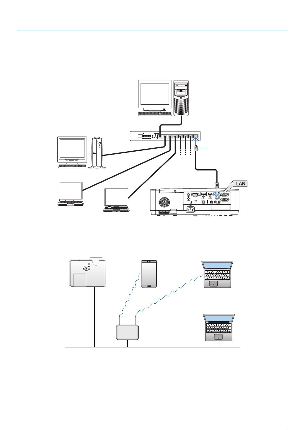
94
6. Installation and Connections
Connecting to a Wired LAN
The projector comes standard with a LAN port (RJ-45) which provides a LAN connection using a LAN cable.
To use a LAN connection, you are required to set the LAN on the projector menu. (→ page
99)
ExampleofLANconnection(1)
Server
Hub
LAN cable (not supplied)
NOTE:UseaCategory5orhigher
LANcable.
ExampleofLANconnection(2)
Via a wireless LAN access point, it enables to easily connect to terminals by INTELLIGENT CONNECTION.
Wired LAN
Wireless access point
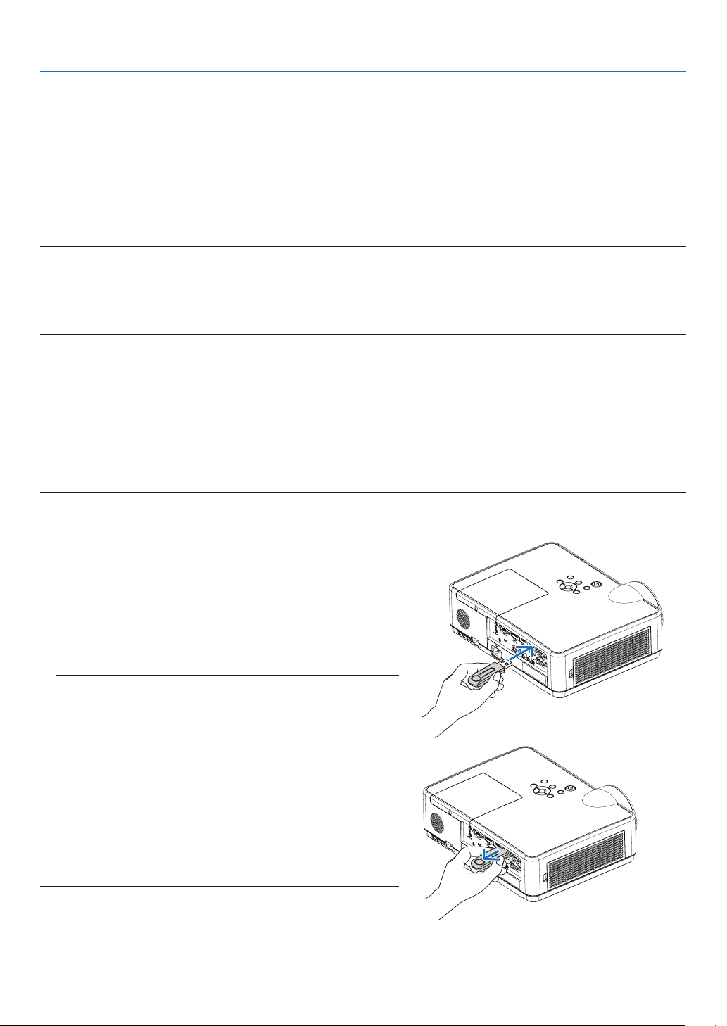
95
6. Installation and Connections
Connecting to a Wireless LAN (Optional: NP05LM series)
The USB Wireless LAN Unit also provides a wireless LAN connection. To use a wireless LAN connection, you are
required to assign an IP address to the projector.
Important:
•IfyouusetheprojectorwiththeUSBWirelessLANUnitintheareawheretheuseofwirelessLANequipmentis
prohibited, remove the USB Wireless LAN Unit from the projector.
•BuytheappropriateUSBWirelessLANUnitforyourcountryorarea.
NOTE:
•ThegreenLEDontheUSBWirelessLANUnitashestoshowthattheUSBWirelessLANUnitisworking.
•Yourcomputer’swirelessLANadapter(orunit)mustbecompliedwithWi-Fi(IEEE802.11b/g/n)standard.
AttachingtheUSBWirelessLANUnit
NOTE:
•TheUSBWirelessLANUnitmustbeinsertedintotheUSBWirelessLANUnitportinthecorrectdirection.Itcannotbeinsertedinthereverse
direction.IftheUSBWirelessLANUnitisinsertedinthereversedirectionwithexcessiveforceapplied,theUSBportmaybreak.
•BeforetouchingtheUSBWirelessLANUnit,touchametallicobject(suchasadoorknoboraluminumwindowframe)todischargethe
staticelectricityfromyourbody.
•AlwaysinsertorremovetheUSBWirelessLANunitwhenthemainpoweristurnedoff.Failuretodosomaycauseprojectormalfunction
ordamagetotheUSBwirelessLANunit.Iftheprojectorwillnotworkcorrectly,turnofftheprojector,disconnectthepowercord,andthen
connectitagain.
•TheUSBportoftheprojectoriscommonusefortheVIEWER.WhentheUSBmemoryisinstalledandactivatetheVIEWER,youcannot
utilizewirelessLAN.
1.PressthePOWERbuttontoturnofftheprojectorandset
it into standby condition, and disconnect the power cord.
2.SlowlyinserttheUSBWirelessLANUnitintotheUSBport.
RemovethecapfromtheUSBWirelessLANUnit,andthen
insertitwiththesurface(sideofindicator)facingdown.Keep
thecapforlateruse.
NOTE:
•DonotforcetoinserttheUSBWirelessLANUnit.
•Setthesuppliedstrapontothestrapxingholeforthemeasureof
anti-theftanddropping-off.
To remove the USB Wireless LAN Unit, disconnect the power
cord and use the above procedure.
NOTE:
•ThegreenLEDontheUSBWirelessLANUnitashestoshowthatWireless
LANUnitisworking.IftheUSBWirelessLANUnitisincorrectlyattached,
theblueLEDwillnotash.
•DonotpressthebuttonontheUSBWirelessLANUnit.Thebuttonwillnot
workwiththismodel.
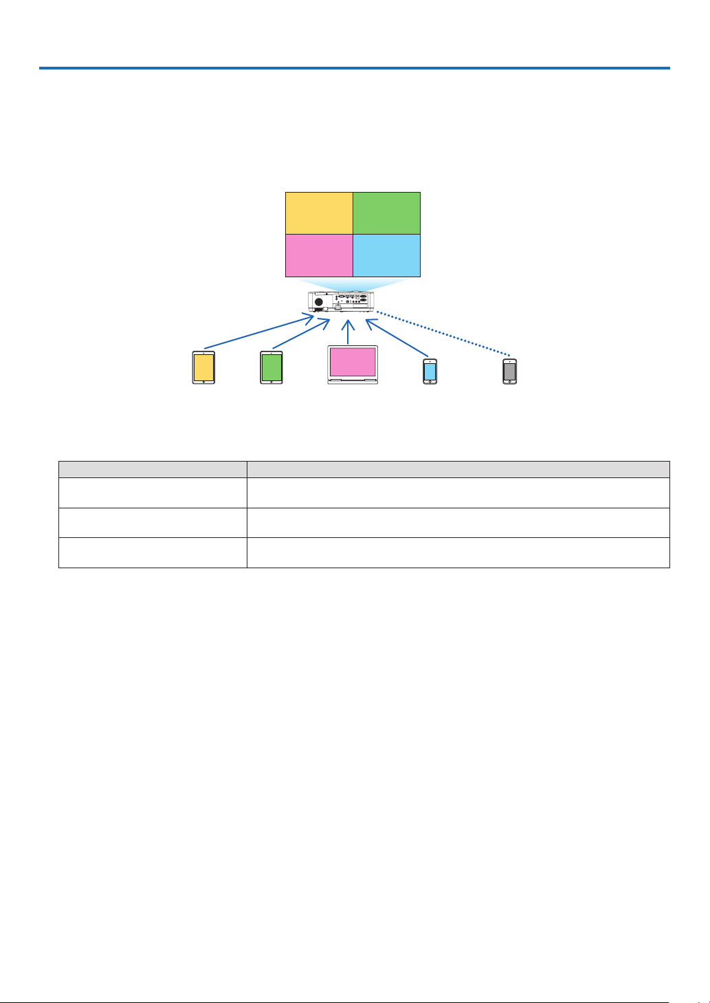
96
7. Connecting to a Network
1 Things you can do by connecting the projector to a network
•YoucansendscreenimagesviaawiredLAN/wirelessLANfromaterminalinstalledwithourMultiPresenterapp
to the projector and project them onto a screen.
See our company’s website for more details about MultiPresenter.
https://www.nec-display.com/dl/en/soft/multipresenter/index.html
B
C
D
E
AB
CD
A
Simultaneous display
Simultaneous connection
Send Send Send Send Stop
•WhenconnectingtheprojectorusingawirelessLAN,youcansetthefollowing3prolesunderthe[NETWORK
SETTINGS] in the menu.
Profile name Description
INTELLIGENT CONNECTION The projector can be easily connected peer-to-peer to a computer or tablet
terminal installed with MultiPresenter.
INFRASTRUCTURE Connect the projector to an existing access point and connect it to a
computer or tablet terminal installed with MultiPresenter.
SIMPLE ACCESS POINT Turn the projector into a simple access point to connect to a computer or
tablet terminal.
•Multiplecomputersortabletterminalscanbeconnectedatthesametime.Amaximumof16unitscanbecon-
nected in the FREE mode and a maximum of 50 units can be connected in the MANAGED mode.
•UsingthewebbrowserofacomputerandtabletterminalconnectedtoawiredLAN/wirelessLAN,youcancon-
nect the projector to a HTTP server to control the projector or configure the NETWORK SETTINGS.
•Byconguringthenetworkservicesettingsoftheprojector,AMXBEACON,HTTPserverlogonpassword,PJLink,
ALERT MAIL, CRESTRON, etc., can be used.
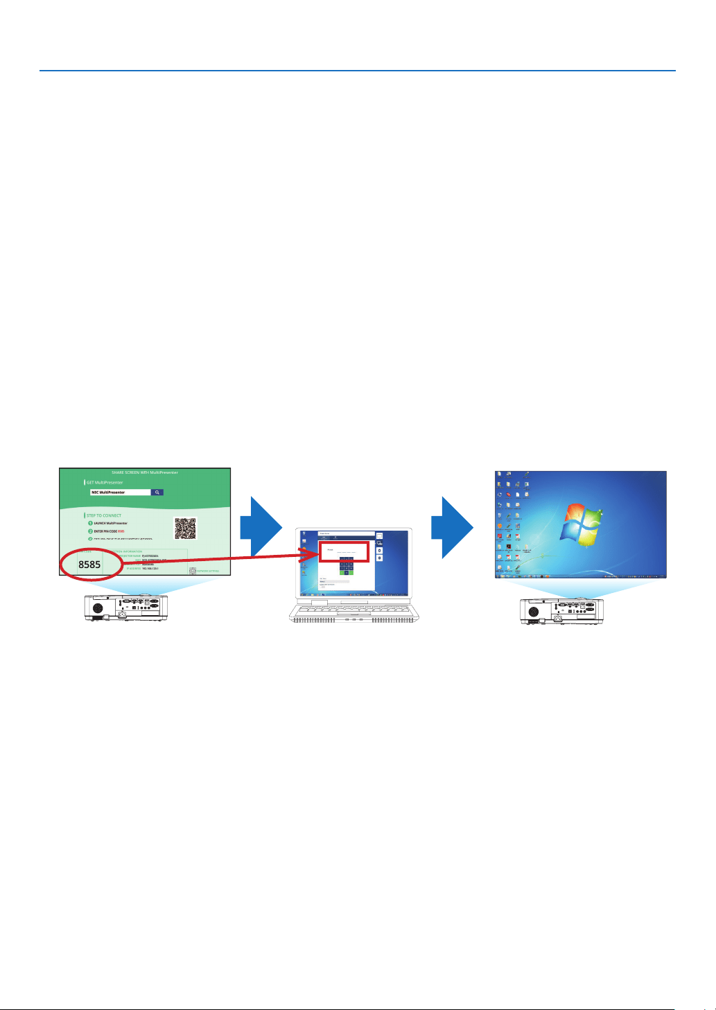
7. Connecting to a Network
97
2 Connecting to MultiPresenter
Preparations:
•WhenconnectingtheprojectortoawiredLAN,connectaLANcabletotheprojector.(→ page
94)
•WhenconnectingtheprojectortoawirelessLAN,installaseparately-sold(ortheenclosed)LANunit(NP05LM)
in the projector. (→ page
95)
•ConguretheNETWORKSETTINGSoftheprojector.(→ page 99)
•InstalltheMultiPresenterappinthecomputerortabletterminal.
https://www.nec-display.com/dl/en/soft/multipresenter/index.html
The procedure is described here for each wireless LAN profile “INTELLIGENT CONNECTION”, “INFRASTRUCTURE”,
and “SIMPLE ACCESS POINT”.
① When connecting with an INTELLIGENT CONNECTION
1.TurnonthepoweroftheprojectorandpresstheAPPSbuttonontheremotecontrol.
The start-up screen of MultiPresenter is displayed.
2.StartMultiPresenter.
The target device screen is displayed.
3. Enter the 4-digit PIN code displayed in the start-up screen in the target device screen.
When connection with the projector is completed, the screen of the computer or tablet terminal is projected on
the screen.

7. Connecting to a Network
98
② When connecting with INFRASTRUCTURE
1.TurnonthepoweroftheprojectorandpresstheAPPSbuttonontheremotecontrol.
The start-up screen of MultiPresenter is displayed.
2.Connecttheprojectorandyourcomputerortabletterminaltothesamenetwork.
NOTE:
•Checkwiththenetworkadministratorforthe“CONNECTIONINFORMATION”ofthenetworktobeconnected.
3.StartMultiPresenter.
The target device screen is displayed.
4. Enter the 4-digit PIN code displayed in the start-up screen in the target device screen.
When connection with the projector is completed, the screen of the computer or tablet terminal is projected on
the screen.
③ When connecting with a SIMPLE ACCESS POINT
1.TurnonthepoweroftheprojectorandpresstheAPPSbuttonontheremotecontrol.
The start-up screen of MultiPresenter is displayed.
2.Connectyourcomputerortabletterminaltotheaccesspointmatchingthe“SSID”displayedinthestart-
up screen.
3.StartMultiPresenter.
The target device screen is displayed.
4. Enter the 4-digit PIN code displayed in the start-up screen in the target device screen.
When connection with the projector is completed, the screen of the computer or tablet terminal is projected on
the screen.
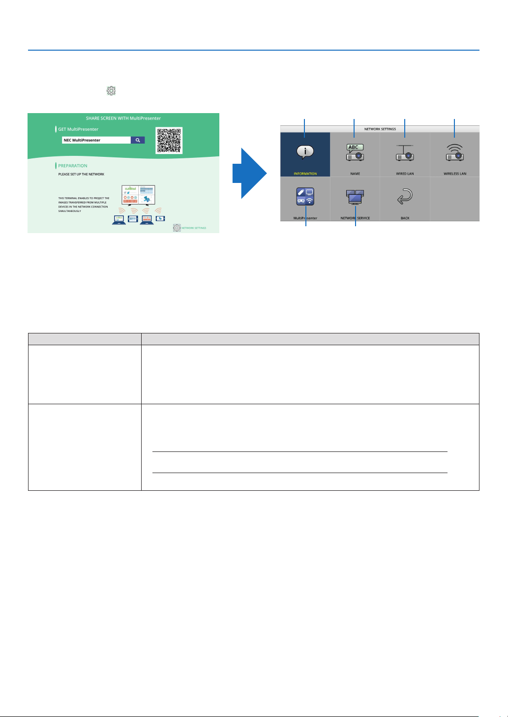
7. Connecting to a Network
99
3 NETWORK SETTINGS
Move the cursor to [
NETWORK SETTINGS] at the bottom right of the start-up screen and press the ENTER button
to display the [NETWORK SETTINGS] screen.
①
⑤ ⑥
② ③ ④
① INFORMATION
Displays information regarding the wired LAN and wireless LAN of the projector.
•ToreturntotheNETWORKSETTINGSscreen,presstheEXITbutton.
② NAME
Sets the PROJECTOR NAME and HOST NAME.
Item name Description
PROJECTOR NAME Set the PROJECTOR NAME.
•Initialvalue:“PJ-XXXXXXXXX”
Theinitialvalue“PJ-XXXXXXXXX”representsthe“PJ-”+“SerialNumber”.
•Allowablecharacters:alphanumericsymbols(includingspace)
•Numberofcharacters:1–16characters
HOST NAME Set the HOST NAME.
•Initialvalue:“pj-XXXXXXXXX”
Theinitialvalue“pj-XXXXXXXXX”representsthe“pj-”+“SerialNumber”.
•Allowablecharacters:alphanumeric,“-”
NOTE:
•Youcannotenter“-”atthebeginningorendoftheHOSTNAME.
•Numberofcharacters:1–16characters
③ WIRED LAN
Configure the PROFILE of the wired LAN, DHCP, IP ADDRESS, SUBNET MASK, GATEWAY, DNS and so on.
•WhenusingawiredLAN,setthePROFILEto[ENABLE]andcongurethenecessarysettings.
•IfyouarenotusingawiredLAN,settheproleto[DISABLE].
•Onceyouhaveconguredthesettings,movethecursorto[OK]andpresstheENTERbutton.
7. Connecting to a Network
100
④ WIRELESS LAN
Configure the wireless LAN settings.
Item name Description
PROFILE There are 4 wireless LAN profiles as shown below.
•DISABLE(initialvalue)
•INTELLIGENTCONNECTION
•SIMPLEACCESSPOINT
•INFRASTRUCTURE
If you are not using a wireless LAN, set the profile to [DISABLE].
The settings of the other 3 profiles are different from each other. This will be
explained later.
DISABLE
Disable the WIRELESS LAN of the projector.
INTELLIGENT CONNECTION
Compared to connecting with infrastructure or a simple access point, it is easier to connect to MultiPresenter that
has been installed in a computer or tablet terminal.
Item name Description
PROFILE INTELLIGENT CONNECTION
MODE Select the wireless mode (IEEE802.11b/g/n or IEEE802.11a/n).
•Initialvalue:IEEE802.11b/g/n
CHANNEL Set the wireless channel.
•Initialvalue:AUTO
SECURITY TYPE Set the SECURITY TYPE (DISABLE or WPA2-PSK).
•Initialvalue:DISABLE
NOTE:
•WhenthePINTYPEsetintheMultiPresentersettingsisONE-TIME,theSECURITYTYPEcannot
bespeciedasitwillbeappliedautomatically.
SECURITY KEY Set the SECURITY KEY.
•Initialvalue:Blank
•Allowablecharacters:alphanumericsymbols(includingspace)
•Numberofcharacters:8–63characters
When a SECURITY KEY is set, a number of asterisks “*” equivalent to the number
of characters is displayed.
NOTE:
•WhenthePINTYPEsetintheMultiPresentersettingsisONE-TIME,theSECURITYKEYcannotbe
setasitwillbesetautomatically.

7. Connecting to a Network
101
SIMPLE ACCESS POINT
Turn the projector into the [SIMPLE ACCESS POINT] to connect computers or tablet terminals installed with
MultiPresenter to the projector.
Item name Description
PROFILE SIMPLE ACCESS POINT
MODE Select the wireless mode (IEEE802.11b/g/n or IEEE802.11a/n).
•Initialvalue:IEEE802.11b/g/n
CHANNEL Set the wireless channel.
•Initialvalue:AUTO
SSID Set the SSID.
•Initialvalue:“AP-XXXXXXXXXX”
Theinitialvalue“AP-XXXXXXXXX”representsthe“AP-”+“SerialNumber”.
•Allowablecharacters:alphanumericsymbols(includingspace)
•Numberofcharacters:1–32characters
SECURITY TYPE Set the SECURITY TYPE (DISABLE or WPA2-PSK).
•Initialvalue:DISABLE
SECURITY KEY Set the SECURITY KEY.
•Initialvalue:Blank
•Allowablecharacters:alphanumericsymbols(includingspace)
•Numberofcharacters:8–63
When the character security key is set, a number of asterisks “*” equivalent to the
number of characters is displayed.
INFRASTRUCTURE
Connect the projector to an existing access point.
Item name Description
PROFILE INFRASTRUCTURE
DHCP, IP ADDRESS,
SUBNET MASK,
GATEWAY, AUTO DNS,
DNS ADDRESS
Set the DHCP, IP address, subnet mask, gateway, auto DNS, and DNS address.
SITE SURVEY Perform a site survey to search for access points.
The SSID and SECURITY TYPE are set according to the selected access point.
SSID Set the SSID.
•Initialvalue:NECPJ
•Allowablecharacters:alphanumericsymbols(includingspace)
•Numberofcharacters:1–32characters
SECURITY TYPE Set the SECURITY TYPE (DISABLE, WPA2-PSK, or WPA/WPA2-PSK).
•Initialvalue:DISABLE
SECURITY KEY Set the SECURITY KEY.
•Initialvalue:Blank
•Allowablecharacters:alphanumericsymbols(includingspace)
•Numberofcharacters:8–63characters
When a SECURITY KEY is set, a number of asterisks “*” equivalent to the number
of characters is displayed.
7. Connecting to a Network
102
⑤ MultiPresenter
Set the MultiPresenter operation.
Item name Description
MODE Select FREE mode or MANAGED mode.
When you are in the MANAGED mode, you can change the split pattern of the
screen by pressing the ENTER button on the remote control of the projector while
projecting the MultiPresenter screen.
•Initialvalue:FREE
NOTE:
•Themodesettingisappliedwhenallconnectionsarecutoff.
PIN TYPE Select ONE-TIME or STATIC.
•Initialvalue:ONE-TIME
•AONE-TIMEPINcodewillbegeneratedautomatically,sothe“PINCODE”can-
not be entered for the next item.
•ForSTATIC,enteranarbitraryPINcode.
PIN CODE Enter a PIN code for [STATIC].
•Initialvalue:4-digitrandomnumber
•Allowablecharacters:numeral
•Numberofcharacters:4characters(0000–9999)
UTILIZE PIN CODE
AS CONNECTION
PASSWORD
Select not to use the PIN code as a password (OFF), or to use the PIN code as a
password (ON).
•Initialvalue:ON
COMMUNICATION SPEED
LIMIT
Set the upper limit of the communication speed that MultiPresenter uses for trans-
mission.
•Initialvalue:DISABLE
START-UP SCREEN
GET APPS GUIDE Select whether or not to display the Get MultiPresenter display on the start-up
screen.
•Initialvalue:ON(display)
CONNECTION STEP
GUIDE
Select whether or not to display the connection procedure on the start-up screen.
•Initial value: ON (display)
CONNECTION
INFORMATION
Select whether or not to display the connection information on the start-up screen.
• Initial value: ON (display)
MultiPresenter SCREEN
CONNECTION
INFORMATION
Select whether or not to display the connection information in the screen when
MultiPresenter is connected.
•Initial value: ON (display)
⑥ NETWORK SERVICE
Configure the AMX BEACON, HTTP SERVER, PJLink, ALERT MAIL, CRESTRON and other settings.
Item name Description
AMX BEACON Select whether or not to transmit AMX beacons.
•Initial value: OFF (do not transmit)
HTTP SERVER Set the password to log into the projector’s HTTP server.
• Initial value: Blank
•Allowablecharacters:alphanumericsymbols
•Numberofcharacters:0–10characters
When a password is set, a number of asterisks “*” equivalent to the number of
characters is displayed.
7. Connecting to a Network
103
Item name Description
PJLink Set the PJLink password.
PASSWORD
SETTINGS
Set the PJLink password.
•Initial value: Blank
•Allowablecharacters:alphanumericcharacters
•Numberofcharacters:0–32characters
When a password is set, a number of asterisks “*” equiva-
lent to the number of characters is displayed.
ALERT MAIL Set alert mail and perform a transmission test.
ALERT MAIL Select whether or not to send an alert mail when an alert target
event occurs in the projector.
•Initial value: OFF (do not transmit)
SENDER’S
ADDRESS
Set the sender’s address when sending E-mail from the
projector.
• Initial value: Blank
•Allowablecharacters:alphanumericcharacters,symbols
•Numberofcharacters:0–60characters
SMTP SERVER
NAME
Set the SMTP server of the network to connect to the
projector.
• Initial value: Blank
•Allowablecharacters:alphanumericcharacters,symbols
•Numberofcharacters:0–60characters
RECIPIENT’S
ADDRESS 1/2/3
Set the destination address to send E-mail from the projector
(maximum 3).
• Initial value: Blank
•Allowablecharacters:alphanumericcharacters,symbols
•Numberofcharacters:0–60characters
TEST MAIL Send a test mail according to the settings.
CRESTRON Set the CRESTRON function.
Crestron Room View
Crestron Room
View
Select whether to use Crestron Room View or not.
•Initial value: OFF (do not use)
Crestron Control
Crestron Control Select whether to use Crestron Control or not.
• Initial value: OFF (do not use)
IP ADDRESS Set the Crestron Control’s IP address.
• Initial value: 192.168.0.100
• Allowable characters: alphanumeric, period
•Numberofcharacters:7–15characters
IP ID Set the Crestron Control’s IP ID.
• Initial value: 5
•Allowablecharacters:alphanumeric
•Inputcharacterrange:3–65535
•Numberofcharacters:1–5characters

7. Connecting to a Network
104
4 Controlling the Projector by Using an HTTP Browser
Overview
The HTTP Server function provides settings and operations for:
•Settingforwired/wirelessnetwork(NETWORKSETTINGS)
To use wireless LAN connection, the optional USB Wireless LAN Unit is required. (→ page
95)
Tousewired/wirelessLANconnection,connecttheprojectortothecomputerwithacommerciallyavailableLAN
cable. (→ page
94)
•SettingAlertMail(ALERTMAIL)
Whentheprojectorisconnectedtoawired/wirelessnetwork,lampreplacetimeorerrormessageswillbesent
via e-mail.
•Operatingtheprojector
Poweron/off,selectinginput,volumecontrolandpictureadjustmentsarepossible.
•SettingPJLinkPASSWORD,HTTPSERVER,ALERTMAIL,AMXBEACON,andCRESTRON
How to access to the HTTP server:
•StarttheWebbrowseronthecomputerviathenetworkconnectedtotheprojectorandenterthefollowing
URL:
http://<theprojector’sIPaddress>/index.html
TIP:ThefactorysettingIPaddressis[DHCPON].
NOTE:
•Tousetheprojectorinanetwork,consultwithyournetworkadministratoraboutnetworksettings.
•Thedisplay’sorbutton’sresponsecanbesloweddownoroperationmaynotbeaccepteddependingthesettingsofyournetwork.
Shouldthishappen,consultyournetworkadministrator.Theprojectormaynotrespondifitsbuttonsarerepeatedlypressedinrapid
intervals.Shouldthishappen,waitamomentandrepeat.Ifyoustillcan’tgetanyresponse,turnoffandbackontheprojector.
•IfthePROJECTORNETWORKSETTINGSscreendoesnotappearinthewebbrowser,presstheCtrl+F5keystorefreshyourwebbrowser
(or clear the cache).
•Thisdeviceuses“JavaScript”and“Cookies”andthebrowsershouldbesettoacceptthesefunctions.Thesettingmethodwillvary
dependingontheversionofbrowser.Pleaserefertothehelplesandtheotherinformationprovidedinyoursoftware.
Preparation before Use
Connect the projector to a commercially available LAN cable before engaging in browser operations. (→ page 94)
Operation with a browser that uses a proxy server may not be possible depending on the type of proxy server and
the setting method. Although the type of proxy server will be a factor, it is possible that items that have actually been
set will not be displayed depending on the effectiveness of the cache, and the contents set from the browser may
not be reflected in operation. It is recommended that a proxy server not be used unless it is unavoidable.
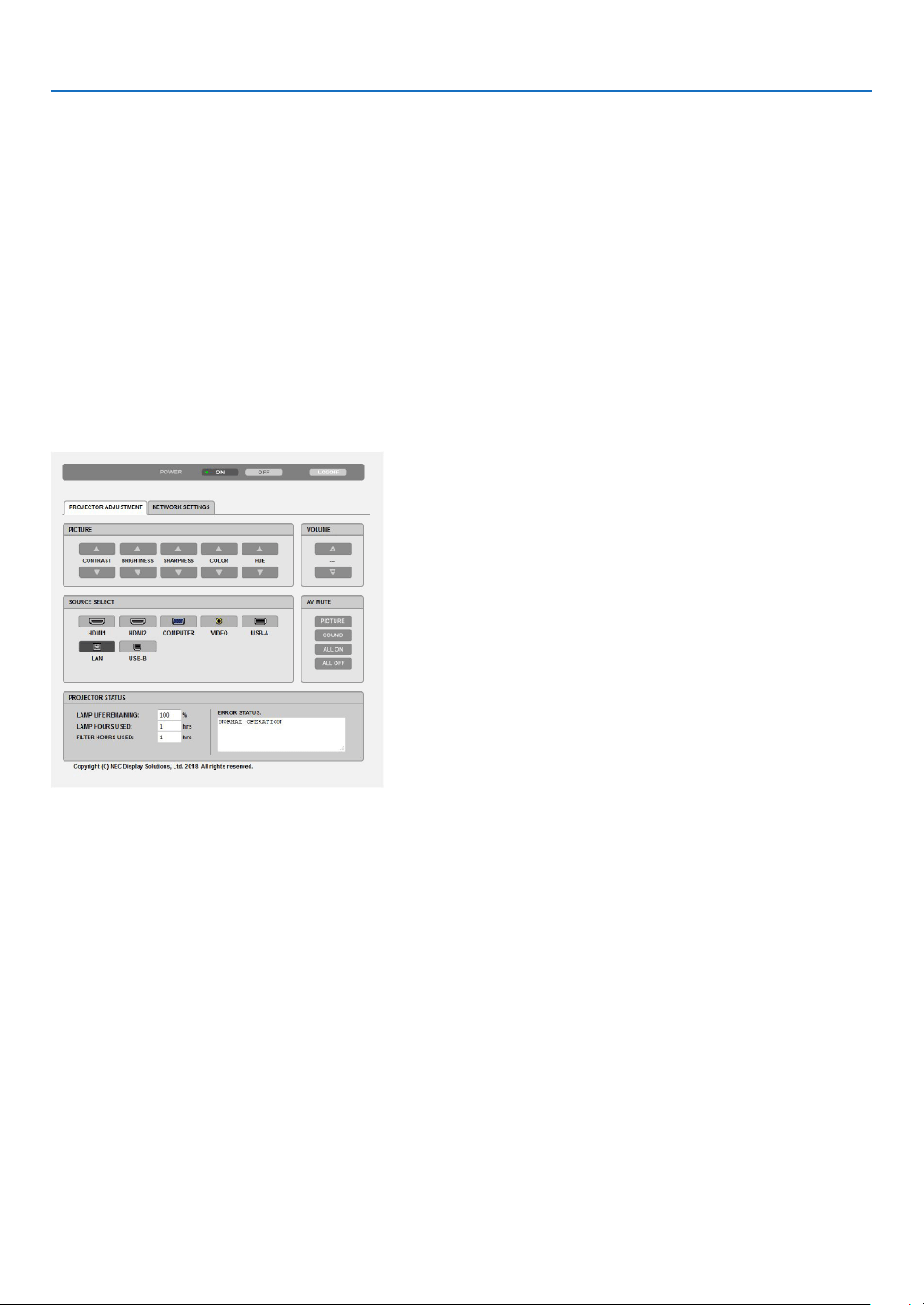
7. Connecting to a Network
105
Handling of the Address for Operation via a Browser
Regarding the actual address that is entered for the address or entered to the URL column when operation of the
projector is via a browser, the host name can be used as it is when the host name corresponding to the IP address
of the projector has been registered to the domain name server by a network administrator, or the host name cor-
responding to the IP address of the projector has been set in the “HOSTS” file of the computer being used.
Example 1: When the host name of the projector has been set to “pj.nec.co.jp”, access is gained to the net-
work setting by specifying
http://pj.nec.co.jp/index.html
for the address or the entry column of the URL.
Example 2: When the IP address of the projector is “192.168.73.1”, access is gained to the network setting by
specifying
http://192.168.73.1/index.html
for the address or the entry column of the URL.
PROJECTOR ADJUSTMENT
POWER: This controls the power of the projector.
ON ���������������������������Power is switched on�
OFF �������������������������� Power is switched off�
VOLUME: This controls the volume of the projector.
▲�����������������������������Increases the volume adjustment value�
▼�����������������������������Decreases the volume adjustment value�
AV-MUTE: This controls the mute function of the projector.
PICTURE ON �������������Mutes the video�
PICTURE OFF ������������Cancels the video muting�
SOUND ON ���������������Mutes the audio�
SOUND OFF ��������������Cancels the audio muting�
ALL ON ���������������������Mutes each of the video, and audio functions�
ALL OFF �������������������Cancels the muting of each of the video, and audio functions�

7. Connecting to a Network
106
PICTURE: Controls the video adjustment of the projector.
CONTRAST ▲�����������Increases the contrast adjustment value�
CONTRAST ▼�����������Decreases the contrast adjustment value�
BRIGHTNESS ▲��������Increases the brightness adjustment value�
BRIGHTNESS ▼��������Decreases the brightness adjustment value�
SHARPNESS ▲���������Increases the sharpness adjustment value�
SHARPNESS ▼���������Decreases the sharpness adjustment value�
COLOR ▲ �����������������Increases the color adjustment value�
COLOR ▼ �����������������Decreases the color adjustment value�
HUE ▲ ���������������������Increases the hue adjustment value�
HUE ▼ ���������������������Decreases the hue adjustment value�
•Thefunctionsthatcanbecontrolledwillvarydependingonthesignalbeinginputtotheprojector.
(→ page
57)
SOURCE SELECT: This switches the input terminal of the projector.
HDMI1 ����������������������Switches to the HDMI 1 IN terminal
HDMI2 ����������������������Switches to the HDMI 2 IN terminal�
COMPUTER ��������������Switches to the COMPUTER IN terminal�
VIDEO �����������������������Switches to the VIDEO IN terminal�
USB-A ���������������������� Switches to the data on the USB memory device�
LAN ��������������������������Switches to a LAN signal�
USB-B ���������������������� Switches to the USB Port�
PROJECTOR STATUS: This displays the condition of the projector.
LAMP LIFE REMAINING ���������� Displays the remaining life of the lamp as a percentage�
LAMP HOURS USED ���������������Displays how many hours the lamp has been used�
FILTER HOURS USED �������������Displays how many hours the filter has been used�
ERROR STATUS ���������������������Displays the status of errors occurring within the projector�
LOG OFF: Logging off your projector and returning to the authentication screen (LOGON screen).
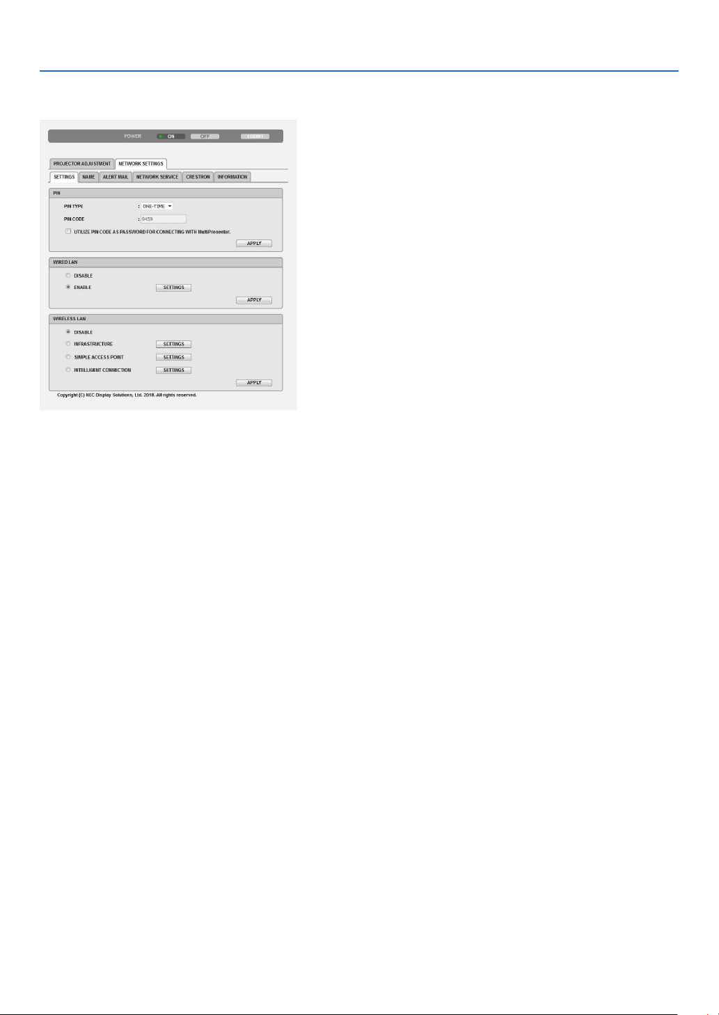
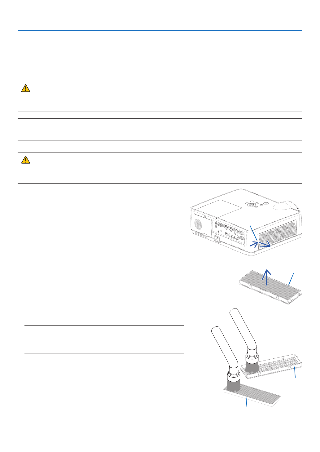
108
8. Maintenance
This section describes the simple maintenance procedures you should follow to clean the filter, the lens, the cabinet,
and to replace the lamp and the filter.
❶ Cleaning the Filter
The air-filter sponge keeps dust and dirt from getting inside the projector and should be frequently cleaned. If the
filter is dirty or clogged, your projector may overheat.
WARNING
•Pleasedonotuseaspraycontainingammablegastoremovedustattachedtothelter,etc.Doingsomay
result in fires.
NOTE:Themessageforltercleaningwillbedisplayedforoneminuteaftertheprojectoristurnedonoroff.Whenthemessageisdisplayed,
cleanthelter.Thetimetocleanthelterissetto[10000H]attimeofshipment.
Tocancelthemessage,pressanybuttonontheprojectorcabinetortheremotecontrol.
To clean the filter, detach the filter unit and the filter cover.
CAUTION
•Beforecleaningthelter,turnofftheprojector,disconnectthepowercordandthenallowthecabinettocool.
Failure to do so can result in electric shock or burn injuries.
1. Push button to release the filter unit and pull it out.
Button
2. Remove the filter.
•Removethelterfromtheltercover.
Filter unit
3. Remove dust from the filter and the filter cover.
•Cleanbothoutsideandinside.
NOTE:
•Wheneveryoudustthelter,usethesoftbrushattachmenttodust.Thisis
toavoiddamagetothelter.
•Donotwashthelterwithwater.Doingsocanresultinlterclogging.
Filter
Filter cover
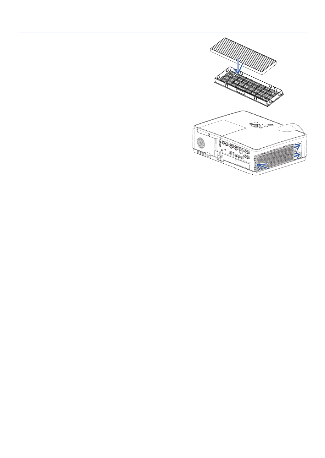
109
8. Maintenance
4. Attach the filter to the filter cover.
5.Putthelterunitbacktotheprojectorcabinet.
Inserttwocatchesofthetipofthelterunitintothegroove
ofthecabinet,andpushthebuttontoclosethelterunit.
•Pushthelterunituntilitclicksintoplace.
6.Clearthelterusagehours.
Plug the power cord into the wall outlet, and then turn on the
projector.
Fromthemenu,select[RESET]→[CLEARFILTERHOURS].
(→ page 77)
Theintervaltimetocleanthelterissetto[OFF]attimeofship-
ment. When using the projector as it is, you do not clear the filter
usage.
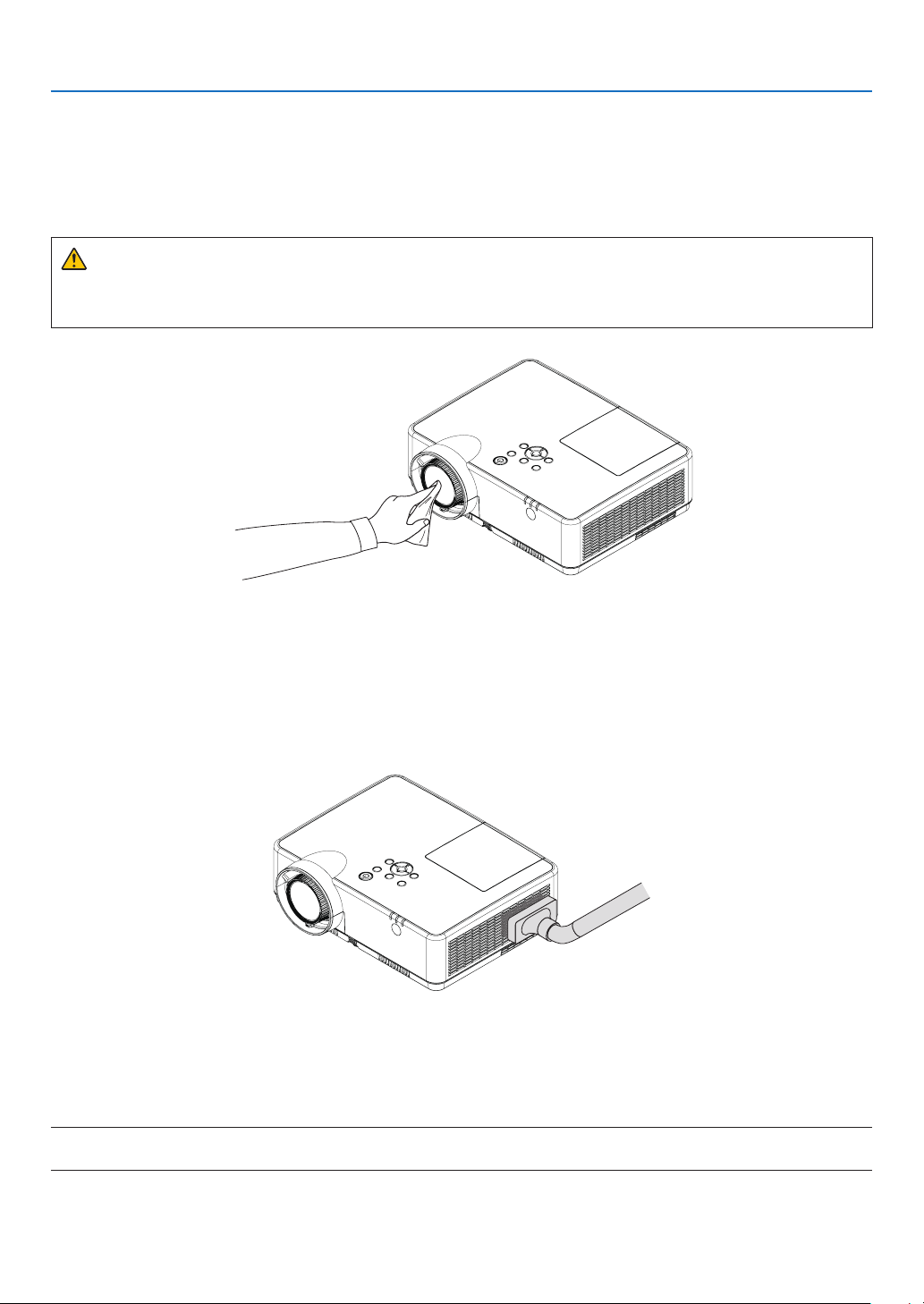
110
8. Maintenance
❷ Cleaning the Lens
•Turnofftheprojectorbeforecleaning.
•Theprojectorhasaplasticlens.Useacommerciallyavailableplasticlenscleaner.
•Donotscratchormarthelenssurfaceasaplasticlensiseasilyscratched.
•Neverusealcoholorglasslenscleanerasdoingsowillcausedamagetotheplasticlenssurface.
WARNING
•Pleasedonotuseaspraycontainingammablegastoremovedustattachedtothelens,etc.Doingsomay
result in fires.
❸ Cleaning the Cabinet
Turn off the projector, and unplug the projector before cleaning.
•Useadrysoftclothtowipedustoffthecabinet.
If heavily soiled, use a mild detergent.
•Neverusestrongdetergentsorsolventssuchasalcoholorthinner.
•Whencleaningtheventsorthespeakerusingavacuumcleaner,donotforcethebrushofthevacuumcleaner
into the slits of the cabinet.
Vacuumthedustoffthevents.
•Cloggedventsmaycauseariseintheinternaltemperatureoftheprojector,resultinginmalfunction.
•Donotscratchorhitthecabinetwithyourngersoranyhardobjects.
•Contactyourdealerforcleaningtheinsideoftheprojector.
NOTE:Donotapplyvolatileagentsuchasinsecticideonthecabinet,thelens,orthescreen.Donotleavearubberorvinylproductinpro-
longedcontactwithit.Otherwisethesurfacenishwillbedeterioratedorthecoatingmaybestrippedoff.

111
8. Maintenance
❹ Replacing the Lamp and the Filter
When the lamp reaches the end of its life, the LAMP indicator in the cabinet will blink ORANGE and the message
“THE LAMP HAS REACHED THE END OF ITS USABLE LIFE. PLEASE REPLACE THE LAMP AND FILTER.” will ap-
pear (*). Even though the lamp may still be working, replace the lamp to maintain the optimal projector performance.
After replacing the lamp, be sure to clear the lamp hour meter. (→ page
77)
CAUTION
•DONOTTOUCHTHELAMPimmediatelyafterithasbeenused.Itwillbeextremelyhot.Turntheprojector
off and then disconnect the power cord. Allow at least one hour for the lamp to cool before handling.
•Usethespeciedlampforsafetyandperformance.
To order the replacement lamp, specify your lamp type, NP47LP.
The replacement lamp comes with filters.
•DONOTREMOVEANYSCREWSexceptonelampcoverscrewandthreelamphousingscrews.Youcould
receive an electric shock.
•Donotbreaktheglassonthelamphousing.
Keep finger prints off the glass surface on the lamp housing. Leaving finger prints on the glass surface might
cause an unwanted shadow and poor picture quality.
•Theprojectorwillturnoffandgointostandbymodewhenyoucontinuetousetheprojectorforanother100
hours after the lamp has reached the end of its life. If this happens, be sure to replace the lamp. If you continue
to use the lamp after the lamp reaches the end of its life, the lamp bulb may shatter, and pieces of glass may be
scattered in the lamp case. Do not touch them as the pieces of glass may cause injury. If this happens, contact
your NEC dealer for lamp replacement.
*NOTE:Thismessagewillbedisplayedunderthefollowingconditions:
•foroneminuteaftertheprojectorhasbeenpoweredon
•whenthe
(POWER)buttonontheprojectorcabinetorthePOWER(STANDBY)buttonontheremotecontrolispressed
Toturnoffthemessage,pressanybuttonontheprojectorcabinetortheremotecontrol.
Optional lamp and tools needed for replacement:
•Phillipsscrewdriver(plus-head)
•Replacementlamp
Flow of Replacing the Lamp and the Filter
Step 1. Replace the lamp
Step 2. Replace the filter (→ page
114)
Step 3.Clearthelampusagehoursandthelterusagehours(→ page
115)
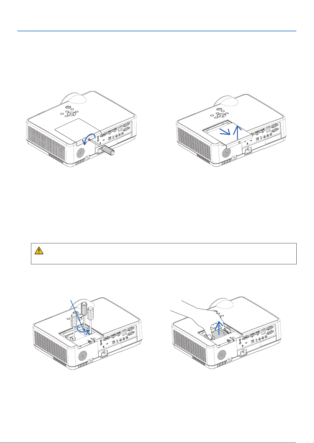
112
8. Maintenance
2. Remove the lamp housing.
(1) Loosen the three screws securing the lamp housing until the phillips screwdriver goes into a freewheeling
condition.
•Thethreescrewsarenotremovable.
•Oneofthescrewsisinterlockedtopreventelectricshock.Donotattempttocircumventthisinterlock.
(2) Remove the lamp housing by holding it.
CAUTION:
Make sure that the lamp housing is cool enough before removing it.
Interlock
Toreplacethelamp:
1. Remove the lamp cover.
(1) Loosen the lamp cover screw.
•Thelampcoverscrewisnotremovable.
(2) Push and slide the lamp cover off.
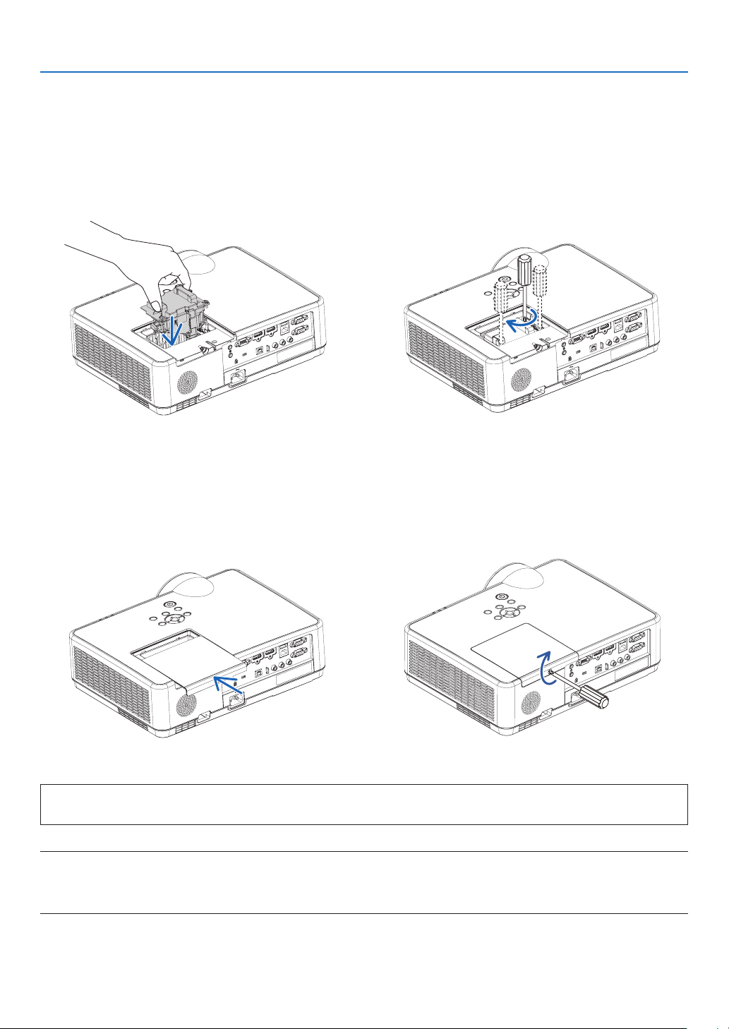
113
8. Maintenance
Thiscompletesthelampreplacement.
Goontothelterreplacement.
NOTE:Whenyoucontinuetousetheprojectorforanother100hoursafterthelamphasreachedtheendofitslife,theprojectorcannotturn
onandthemenuisnotdisplayed.
Ifthishappens,presstheHELPbuttonontheremotecontrolfor10secondstoresetthelampclockbacktozero.
Whenthelamptimeclockisresettozero,theLAMPindicatorgoesout.
4. Reattach the lamp cover.
(1) Slide the lamp cover back until it snaps into place.
(2) Tighten the screw to secure the lamp cover.
•Besuretotightenthescrew.
3. Install a new lamp housing.
(1) Insert a new lamp housing until the lamp housing is plugged into the socket.
(2) Push the top center of the lamp housing to secure it.
(3) Secure it in place with the three screws.
•Besuretotightenthescrews.
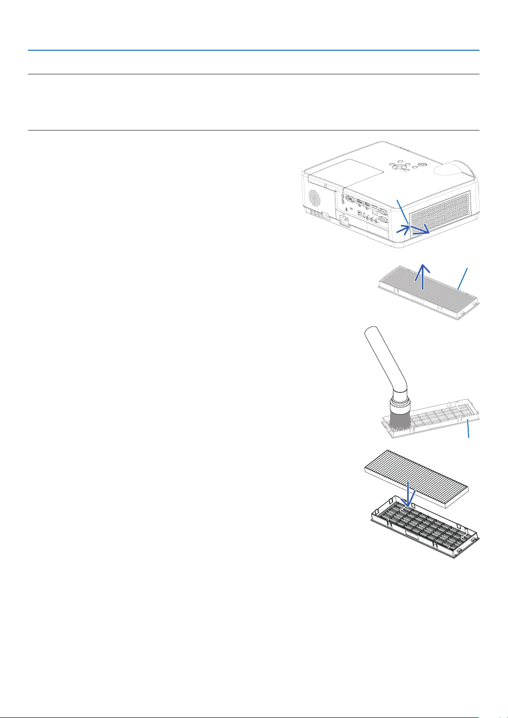
114
8. Maintenance
Toreplacethelter:
NOTE:
•Beforereplacingthelter,wipeoffdustanddirtfromtheprojectorcabinet.
•Theprojectorisprecisionequipment.Keepoutdustanddirtduringlterreplacement.
•Donotwashthelterwithsoapandwater.Soapandwaterwilldamagetheltermembrane.
•Putlterintoplace.Incorrectattachmentofaltermaycausedustanddirttogetintotheinsideoftheprojector.
1. Push button to release the filter unit and pull it out.
Button
2. Remove the filter.
•Removethelterfromtheltercover.
Filter unit
3. Remove dust from the filter cover.
•Cleanbothoutsideandinside.
Filter cover
4. Attach a new filter to the filter cover.
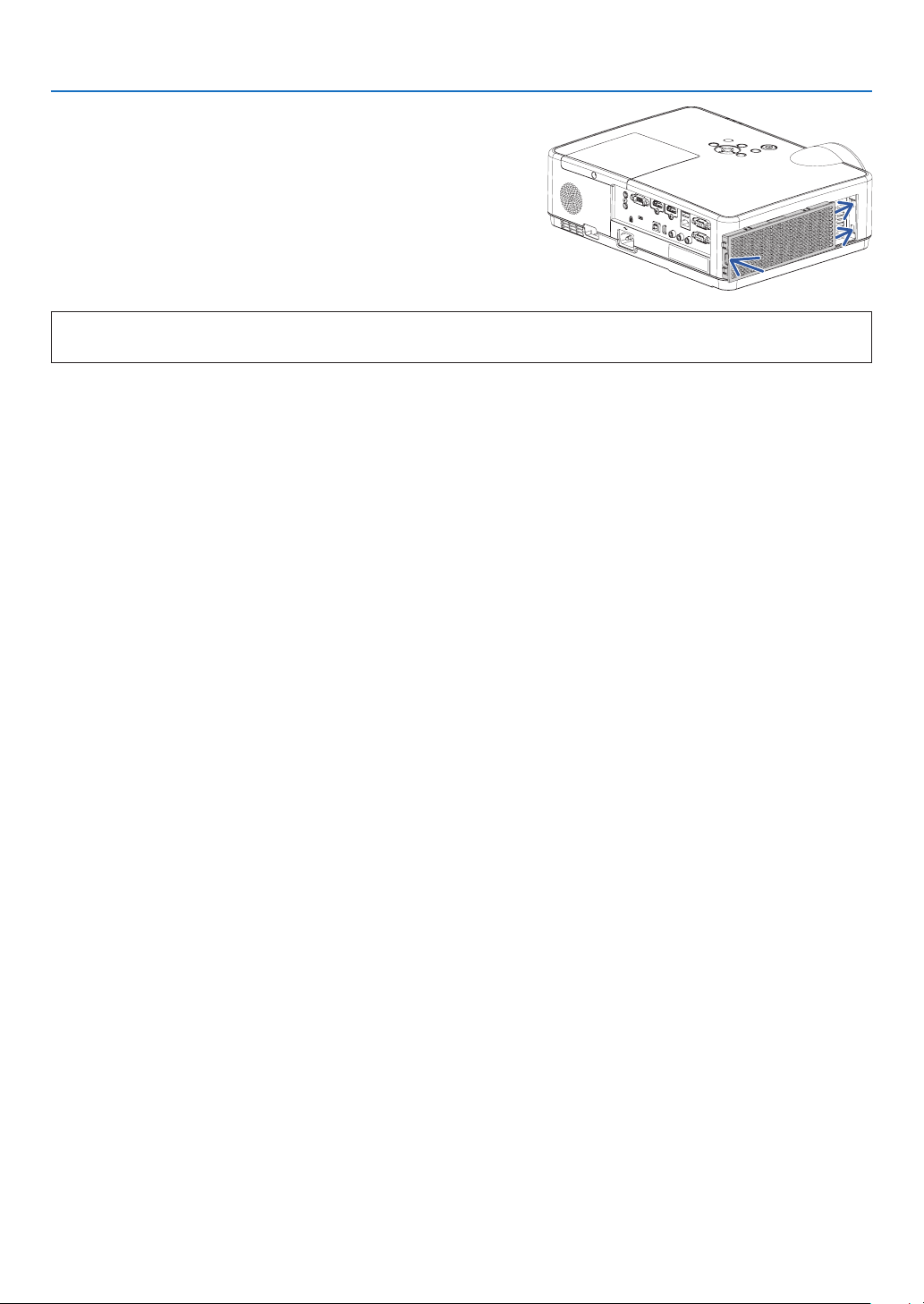
115
8. Maintenance
5.Putthelterunitbacktotheprojectorcabinet.
Inserttwocatchesofthetipofthelterunitintothegrooveof
the cabinet, and push the button to close the filter unit.
•Pushthelterunituntilitclicksintoplace.
Thiscompletesthelterreplacement.
Goontotheclearinglampandlterhourmeters.
Toclearthelampusagehoursandthelterusagehours:
1.Placetheprojectorwhereyouuseit.
2.Plugthepowercordintothewalloutlet,andthenturnontheprojector.
3.Clearthelampusagehoursandthelterusagehours.
1.Fromthemenu,select[RESET]→[CLEARLAMPHOURS]andresetthelampusagehours.
2.Select[CLEARFILTERHOURS]andresetthelterusagehours.(→ page
77)
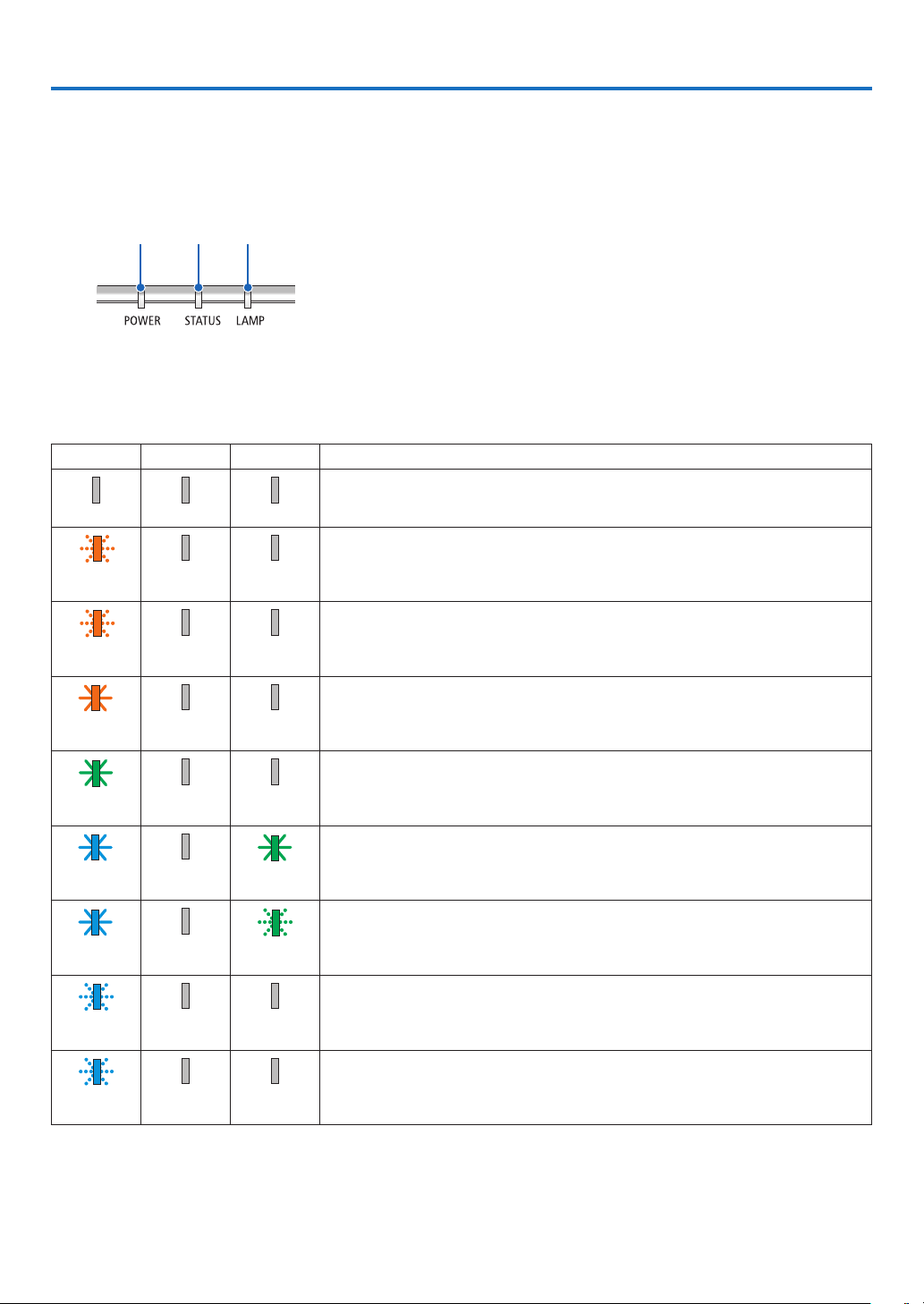
116
9. Appendix
❶ Troubleshooting
This section helps you resolve problems you may encounter while setting up or using the projector.
Feature of each indicator
①
②
③
① POWER indicator
This indicator informs the power status of the projector.
② STATUS indicator
This indicator lights/blinks when a button is pressed while the
CONTROL PANEL LOCK function is utilized, or while performing the
specific operations.
③ LAMP indicator
This indicator informs the state of lamp, usage time of the lamp, and
the status of ECO MODE.
Indicator Message (Status message)
POWER STATUS LAMP Projector status
Power is off
Off Off Off
In the state of Standby (Standby mode is NETWORK STANDBY and network is
ready)
Orange
(Blink*
1
)
Off Off
In the state of Standby (Network is unavailable)
Orange
(Blink*
2
)
Off Off
In the state of Standby (Standby mode is NETWORK STANDBY and network is
available)
Orange
(Light)
Off Off
In the state of Sleep
Green
(Light)
Off Off
Powered state (ECO mode is OFF)
Blue
(Light)
Off Green
(Light)
Powered state (ECO mode is ON)
Blue
(Light)
Off Green (Blink*
3
)
OFF Timer is activated, OFF time as the program timer is activated (Powered state)
Blue
(Blink*
3
)
Off Status varies
Preparing for powering ON
Blue
(Blink*
4
)
Off Off
*1 Repetition to light on for 1.5 seconds / off for 1.5 seconds
*2 Repetition to light on for 1.5 seconds / off for 7.5 seconds
*3 Repetition to light on for 2.5 seconds / off for 0.5 seconds
*4 Repetition to light on for 0.5 seconds / off for 0.5 seconds
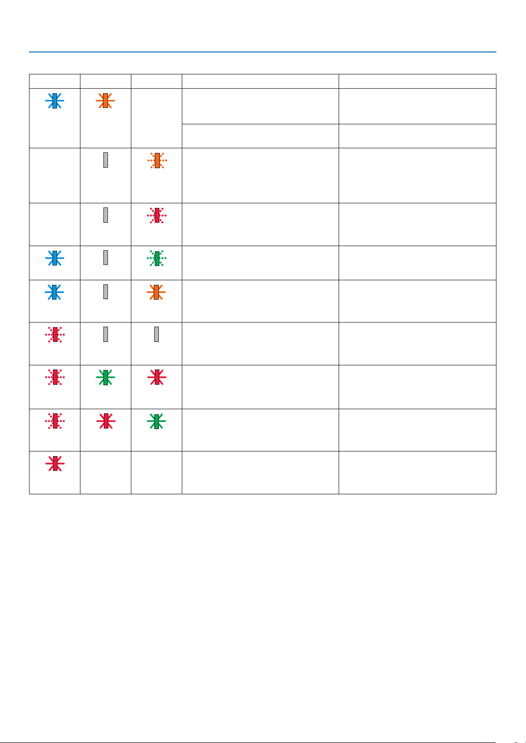
117
9. Appendix
Indicator Message (Error message)
POWER STATUS LAMP Projector status Procedure
A button has been pressed while the
KEY LOCK is activated.
The projector's keys are locked. The
setting must be canceled to operate the
projector. (→ page 67)
Blink Orange
(Light)
Status varies
ID numbers for the projector and the
remote control do not match.
Check the control IDs (
→ page
68)
Lamp replacement grace period. The lamp has reached the end of its
service life and is now in the replacement
grace period (100 hours). Replace the
lamp to new one as soon as possible.
(→ page 111)
Status varies Off Orange
(Blink*
4
)
Lamp replacement time exceeded. The lamp has exceeded its replacement
time. Replace the lamp immediately.
Status varies Off Red
(Blink*
4
)
Preparing to relight lamp after lighting
has failed.
Wait a while.
Blue (Blink*
4
) Off Green (Blink*
4
)
Temperature problem (In the Forced
ECO)
Ambient temperature is high. Lower the
room temperature.
Blue
(Light)
Off Orange
(Light)
Temperature problem Ambient temperature is out of the opera-
tion temperature. Check if any obstruction
stays near the exhaust vent.
Red
(Blink*
4
)
Off Off
Lamp does not light. Wait at least 1 minute, then turn on the
power back on. If the lamp still does
not light, contact your dealer or service
personnel.
Red
(Blink*
4
)
Green
(Light)
Red
(Light)
Lamp cover problem Lamp cover is not mounted properly.
Mount it (→ see page 113).
Red
(Blink*
4
)
Red
(Light)
Green
(Light)
Error requiring service support Contact your dealer or service personnel.
Make sure to check and inform indicator
status for asking to repair.
Red
(Light)
Status varies Status varies
*1 Repetition to light on for 1.5 seconds / off for 1.5 seconds
*2 Repetition to light on for 1.5 seconds / off for 7.5 seconds
*3 Repetition to light on for 2.5 seconds / off for 0.5 seconds
*4 Repetition to light on for 0.5 seconds / off for 0.5 seconds
•Whenthethermalprotectorisactivated:
When inside temperature of the projector becomes too high or low, the POWER indicator start to red blink in a
short cycle. After this happened, the thermal protector will activate and the projector may be turned off.
In this case, please take the below measures:
- Pull out the power plug from the wall inlet.
- Place the projector in cool place if it has been placed in high ambient temperature.
- Clean the exhaust vent if dust has accumulated on.
- Leave the projector for about one hour until inside temperature gets lower.
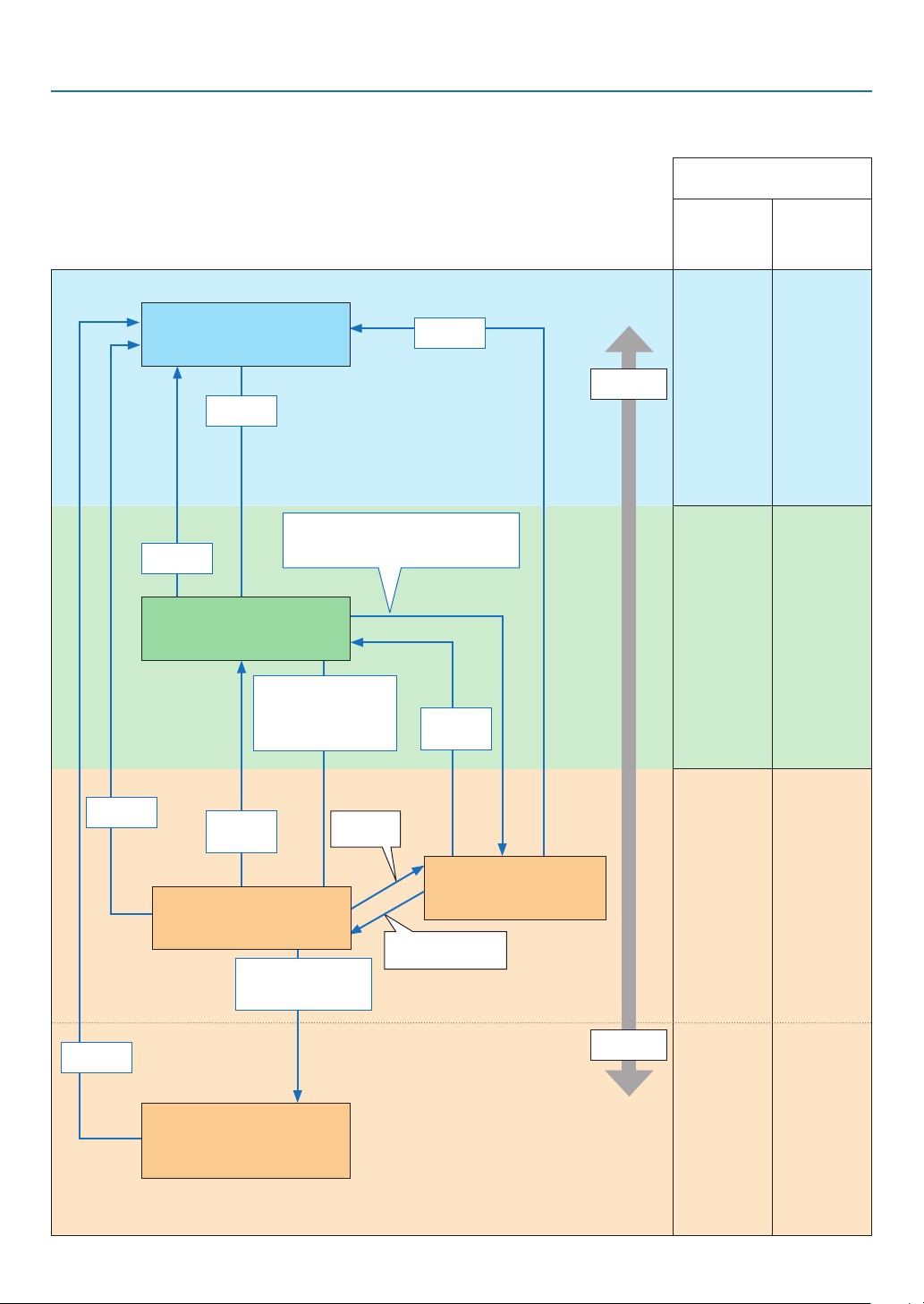
118
9. Appendix
Explanation on the POWER indicator and standby state
InthestatetheselectedSTANBYMODEisNETWORKSTANDBY.
Available ports in each state
(
○: Available, ×: Unavailable)
LAN
PC
CONTROL
○ ○
○ ○
○ ○
× ○
Power
consumption
High
Low
Indicator:Lightsinblue
Powered On state
Indicator:Lightsinorange
Standby state: The network
is linked.
Link-up
network
Link-down network
No operation/Link-
down network/No
signal input for approx.
180 seconds
Link-down for approx.
180 seconds
No operation/No communication with
the link-up network / No signal input for
approx. 180 seconds
Power Off
Power On
Power On
Input
signal
Indicator:Blinksinorange(with
longinterval)
Standby state : The network is
unavailable.
Power On
Input
signal
Indicator:Lightsingreen
Sleep state
Indicator:Blinksinorange
Standby state : Waiting to link
with the network
Power On
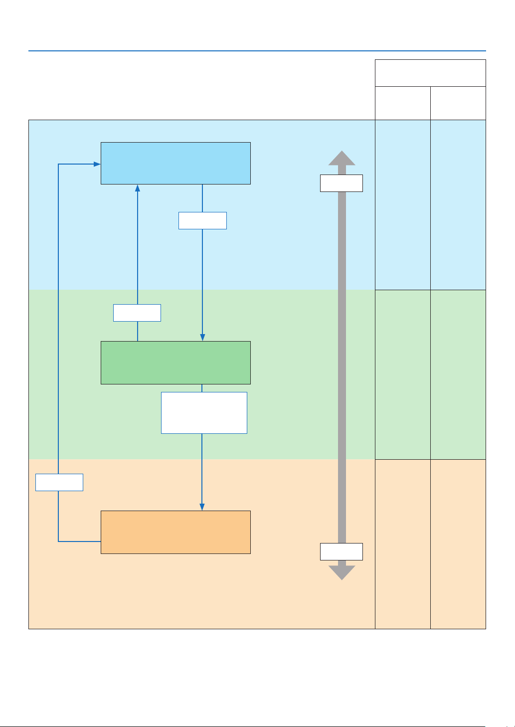
119
9. Appendix
InthestatetheselectedSTANBYMODEisNORMAL.
Available ports in each state
(
○: Available, ×: Unavailable)
LAN
PC
CONTROL
○ ○
○ ○
× ○
Power
consumption
High
Low
Indicator:Lightsinblue
Powered ON state
Power On
No operation/No signal
input for approx.
10 seconds
Power Off
Power On
Indicator:Blinksinorange(withlong
interval)
Standby state : The network is unavailable.
Indicator:Lightsingreen
Sleep state

120
9. Appendix
Common Problems & Solutions
(→ “Power/Status/Lamp Indicator” on page
116.)
ProblemCheckTheseItems
Does not turn on or shut
down
• Check that the power cord is plugged in and that the power button on the projector cabinet or the remote control is on.
(→ pages
11, 12)
• Ensure that the lamp cover is installed correctly. (→ page
113)
• Check to see if the projector has overheated. If there is insufcient ventilation around the projector or if the room where
you are presenting is particularly warm, move the projector to a cooler location�
• Check to see if you continue to use the projector for another 100 hours after the lamp has reached the end of its life. If
so, replace the lamp� After replacing the lamp, reset the lamp hours used� (→ page
77)
• The lamp may fail to light. Wait a full minute and then turn on the power again.
• Set [FAN MODE] to [HIGH ALTITUDE] when using the projector at altitudes approximately 5500 feet/1700 meters or higher.
Using the projector at altitudes approximately 5500 feet/1700 meters or higher without setting to [HIGH ALTITUDE] can
cause the projector to overheat and the projector could shut down� If this happens, wait a couple minutes and turn on
the projector� (→ page 69)
If you turn on the projector immediately after the lamp is turned off, the fans run without displaying an image for some
time and then the projector will display the image� Wait for a moment�
Will turn off
• Ensure that the [OFF TIMER] or [AUTO POWER OFF] is off. (→ page
64, 72)
No picture • Use the COMPUTER, HDMI1, HDMI2, VIDEO, USB-A, USB-B or APPS button on the remote control to select your source
(COMPUTER, HDMI1, HDMI2, VIDEO, USB-A, LAN or USB-B)� (→ page 14) If there is still no picture, press the button again�
• Ensure your cables are connected properly.
• Use menus to adjust the brightness and contrast. (→ page 57)
• Reset the settings or adjustments to factory preset levels using the [RESET] in the Menu. (→ page 77)
• Enter your registered keyword if the Security function is enabled. (→ page 30)
• Be sure to connect the projector and notebook PC while the projector is in standby mode and before turning on the power
to the notebook PC�
In most cases the output signal from the notebook PC is not turned on unless connected to the projector before being
powered up�
* If the screen goes blank while using your remote control, it may be the result of the computer’s screen-saver or power
management software�
• See also the next page�
Picture suddenly
becomes dark
• Check if the projector is in the Forced ECO mode because of too high ambient temperature. (→ page
69)
Color tone or hue is
unusual
• Check if an appropriate color is selected in [WALL COLOR]. If so, select an appropriate option. (→ page
64)
• Adjust [HUE] in [PICTURE]. (→ page 57)
Image isn’t square to the
screen
• Reposition the projector to improve its angle to the screen. (→ page
15, 16)
• Use the Keystone correction function to correct the trapezoid distortion. (→ page 18)
Picture is blurred
• Adjust the focus. (→ page
17)
• Reposition the projector to improve its angle to the screen. (→ page 15, 16)
• Ensure that the distance between the projector and screen is within the adjustment range. (→ page 85)
• Condensation may form on the lens if the projector is cold, brought into a warm place and is then turned on. Should this
happen, let the projector stand until there is no condensation on the lens�
Flicker appears on screen •
Set [FAN MODE] to other than [HIGH ALTITUDE] mode when using the projector at altitudes approximately 5500 feet/1700 meters
or lower� Using the projector at altitudes less than approximately 5500 feet/1700 meters and setting to [HIGH ALTITUDE] can cause
the lamp to overcool, causing the image to flicker� Switch [FAN MODE] to [AUTO]� (→ page 69)
Image is scrolling verti-
cally, horizontally or both
• Check the computer’s resolution and frequency. Make sure that the resolution you are trying to display is supported by
the projector� (→ page 127)
• Adjust the computer image manually with the Horizontal/Vertical in the [IMAGE OPTIONS]. (→ page 59)
Remote control does not
work
• Install new batteries. (→ page
9)
• Make sure there are no obstacles between you and the projector.
• Stand within 22 feet (7 m) of the projector. (→ page 9)
Indicator is lit or blinking
• See the POWER/STATUS/LAMP Indicator. (→ page
116)
Cross color in RGB mode
• Press the AUTO ADJ. button on the projector cabinet or the remote control. (→ page
20)
• Adjust the computer image manually with [CLOCK]/[PHASE] in [IMAGE OPTIONS] in the menu. (→ page 58)
For more information contact your dealer.

121
9. Appendix
If there is no picture, or the picture is not displayed correctly.
•PoweronprocessfortheprojectorandthePC.
Be sure to connect the projector and notebook PC while the projector is in standby mode and before turning on
the power to the notebook PC.
In most cases the output signal from the notebook PC is not turned on unless connected to the projector before
being powered up.
NOTE:Youcancheckthehorizontalfrequencyofthecurrentsignalintheprojector’smenuunderInformation.Ifitreads“0kHz”,this
meansthereisnosignalbeingoutputfromthecomputer.(→page
75orgotonextstep)
•Enablingthecomputer’sexternaldisplay.
Displaying an image on the notebook PC’s screen does not necessarily mean it outputs a signal to the projector.
When using a PC compatible laptop, a combination of function keys will enable/disable the external display. Usu-
ally, the combination of the “Fn” key along with one of the 12 function keys gets the external display to come on
oroff.Forexample,NEClaptopsuseFn+F3,whileDelllaptopsuseFn+F8keycombinationstotogglethrough
external display selections.
•Non-standardsignaloutputfromthecomputer
If the output signal from a notebook PC is not an industry standard, the projected image may not be displayed
correctly. Should this happen, deactivate the notebook PC’s LCD screen when the projector display is in use.
Each notebook PC has a different way of deactivate/reactivate the local LCD screens as described in the previ-
ous step. Refer to your computer’s documentation for detailed information.
•ImagedisplayedisincorrectwhenusingaMac
When using a Mac with the projector, set the DIPswitch of the Mac adapter (not supplied with the projector) ac-
cording to your resolution. After setting, restart your Mac for the changes to take affect.
For setting display modes other than those supported by your Mac and the projector, changing the DIP switch
on a Mac adapter may bounce an image slightly or may display nothing. Should this happen, set the DIP switch
to the 13" fixed mode and then restart your Mac. After that, restore the DIP switches to a displayable mode and
then restart the Mac again.
NOTE:AVideoAdaptercablemanufacturedbyAppleInc.isneededforaMacBookwhichdoesnothaveaminiD-Sub15-pinterminal.
•MirroringonaMacBook
* When using the projector with a MacBook, output may not be set to 1024 × 768 unless “mirroring” is off on
your MacBook. Refer to owner’s manual supplied with your Mac computer for mirroring.
•FoldersoriconsarehiddenontheMacscreen
Folders or icons may not be seen on the screen. Should this happen, select [View] → [Arrange] from the Apple
menu and arrange icons.
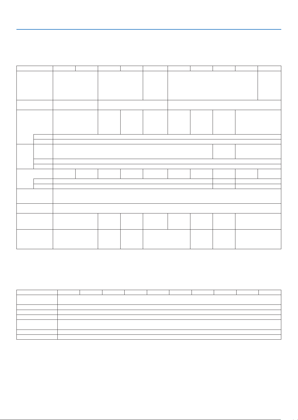
122
9. Appendix
❷ Specifications
This section provides technical information about projector’s performance.
Optical
ModelNumberME382UME342UMC382WME372WMC332WMC422XME402XMC372XMC342XMC302X
LCD Panel 0.64 inch LCD with
Micro Lens Array
(Aspect Ratio 16:10)
0.64 inch LCD with
Micro Lens Array
(Aspect Ratio 16:10)
0.59 inch
LCD with
Micro Lens
Array
(Aspect
Ratio 16:10)
0.63 inch LCD with Micro Lens Array
(Aspect Ratio 4:3)
0.63 inch
LCD
(Aspect
Ratio 4:3)
Resolution*
1
WUXGA
(1920 dots × 1200 lines)
WXGA (1280 dots × 800 lines) XGA (1024 dots × 768 lines)
Lens ZOOM Ratio = 1.6
F=1.5-2.1 /
f=17.2-27.7 mm
ZOOM
Ratio=1.2
F=1.6-1.8 /
f=19.2-
23.0 mm
ZOOM
Ratio=1.7
F=1.7-2.2 /
f=17.4-
29.0 mm
ZOOM
Ratio=1.2
F=1.6-1.8 /
f=19.2-
23.0 mm
ZOOM
Ratio=1.2
F=1.6-1.8 /
f=19.2-
23.0 mm
ZOOM
Ratio=1.7
F=1.7-2.2 /
f=17.4-
29.0 mm
ZOOM
Ratio=1.2
F=1.6-1.8 /
f=19.2-
23.0 mm
ZOOM Ratio=1.2
F=2.1-2.3 /
f=19.1-22.9 mm
Zoom Manual
Focus Manual
Lamp ECO
MODE
OFF
225 W 210 W 225 W
NORMAL 180 W
ECO 151 W
Light
Output*
2
*
3
3800 lm 3400 lm 3800 lm 3700 lm 3300 lm 4200 lm 4000 lm 3700 lm 3400 lm 3000 lm
NORMAL Approx. 80% 86% 80%
ECO Approx. 67% 72% 67%
Contrast Ratio
(full white/full
black)
16000:1 with Iris
Screen Size
(Diagonal)
30-300 inches
Projection
Distance
(Min.-Max.)
29-507 inches /
0.7-12.9 m
34-421
inches /
0.9-10.7 m
30-528
inches /
0.8-13.4 m
38-457
inches /
1.0-11.6 m
35-431
inches /
0.9-10.9 m
31-542
inches /
0.8-13.8 m
35-431
inches /
0.9-10.9 m
34-429 inches /
0.9-10.9 m
Projection Angle 11.0°-11.7°(Wide)/
6.8°-7.1°(Tele)
10.2°-10.6°
(Wide) /
8.5°-8.7°
(Tele)
10.8°-11.5°
(Wide) /
6.6°-6.8°
(Tele)
10.2°-10.3°(Wide)/
8.5°-8.6°(Tele)
10.7°-11.4°
(Wide) /
6.5°-6.8°
(Tele)
10.2°-10.3°
(Wide) /
8.5°-8.6°
(Tele)
10.2°-10.6°(Wide)/
8.5°-8.8°(Tele)
*1 Effective pixels are more than 99.99%.
*2 This is the light output value (lumens) when the [PRESET] mode is set to [HIGH-BRIGHT]. If any other mode is selected as the [PRESET] mode,
the light output value may drop slightly.
*3 Compliance with ISO21118-2012
Electrical
ModelNumberME382UME342UMC382WME372WMC332WMC422XME402XMC372XMC342XMC302X
Inputs 1 × RGB/Component (D-SUB 15 P), 2 × HDMI Type A (19P, HDMI
®
Terminal) HDCP supported*
4
, 1 × Video (RCA),
1 × (L/R) RCA Audio, 1 × Stereo Mini Audio
Outputs 1 × RGB (D-Sub 15 P), 1 × Stereo Mini Audio
PC Control 1 × PC Control Port (D-Sub 9 P)
Wired LAN Port 1 × RJ-45 (10BASE-T/100BASE-TX)
Wireless LAN Port
(Optional)
IEEE 802.11 b/g/n (optional USB Wireless LAN Unit required)
USB Port 1 × Type A, 1 × Type B
Color Reproduction 10-bit signal processing (1.07 billion colors) (VIEWER, Network: 16.7 million colors)
*4 HDMI
®
(Deep Color, Lip Sync) with HDCP
What is HDCP/HDCP technology?
HDCP is an acronym for High-bandwidth Digital Content Protection. High bandwidth Digital Content Protection (HDCP) is a system for preventing
illegal copying of video data sent over a High-Definition Multimedia Interface (HDMI).
If you are unable to view material via the HDMI input, this does not necessarily mean the projector is not functioning properly. With the implemen-
tation of HDCP, there may be cases in which certain content is protected with HDCP and might not be displayed due to the decision/intention of
the HDCP community (Digital Content Protection, LLC).
Video: Deep Color; 8/10/12-bit, LipSync
Audio: LPCM; up to 2 ch, sample rate 32/44.1/48 KHz, sample bit; 16/20/24-bit
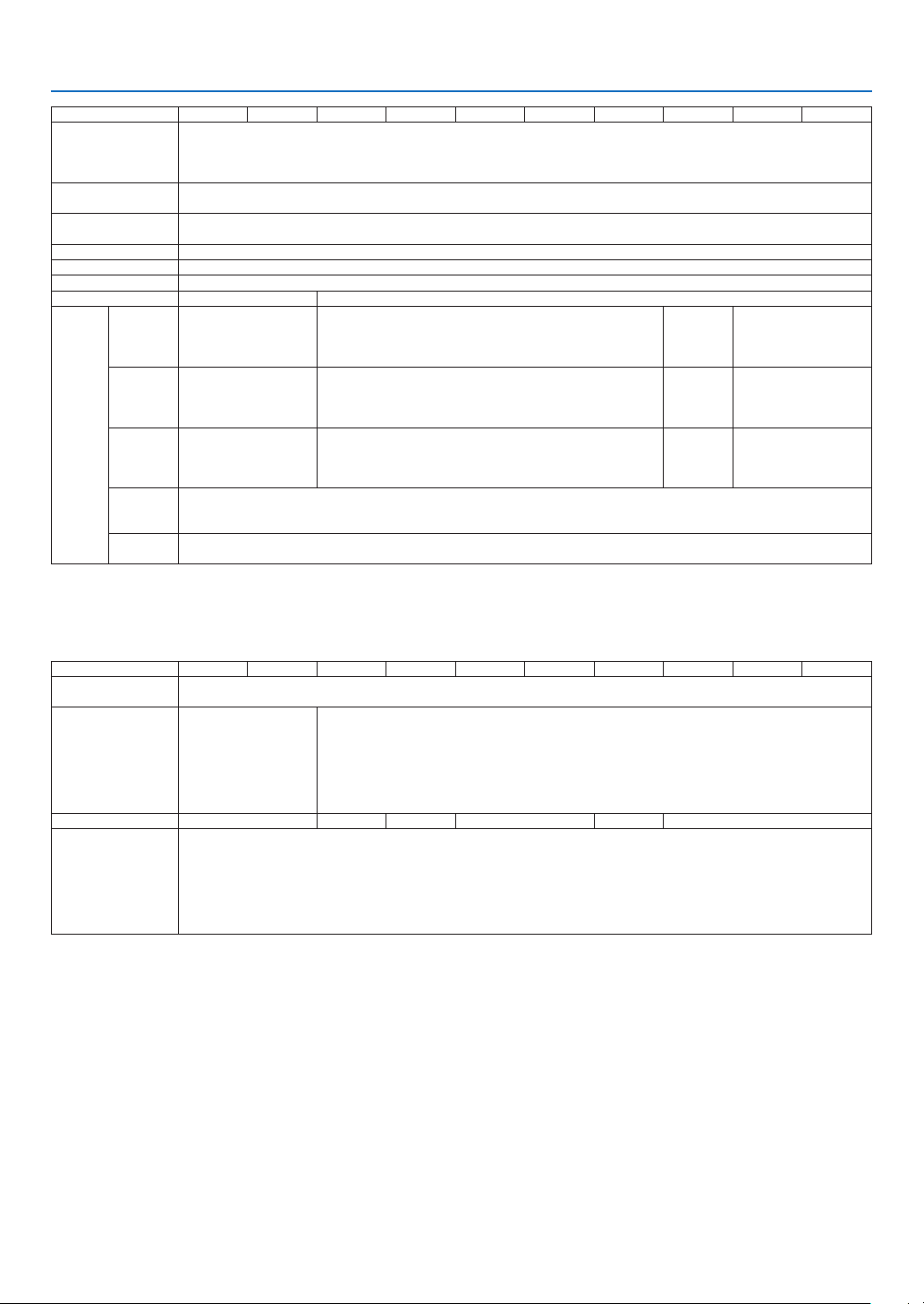
123
9. Appendix
Model Number ME382U ME342U MC382W ME372W MC332W MC422X ME402X MC372X MC342X MC302X
Compatible Signals*
5
Analog: VGA/SVGA/XGA/WXGA/Quad-VGA/SXGA/SXGA+/WXGA+/WXGA++/UXGA/WSXGA+/HD/Full HD/WUXGA/
Mac 13", 16", 21", 23"
Component: 480i/480p/576i/576p/720p/1080i/1080p
HDMI: VGA/SVGA/XGA/WXGA/Quad-VGA/SXGA/SXGA+/WXGA+ /WXGA++/WSXGA+/4K/480p/576p/720p/1080i/1080p
Horizontal Resolution 540 TV lines: NTSC/NTSC4.43/PAL/PAL-M/PAL-N/PAL60
300 TV lines: SECAM
Scan Rate Horizontal: 15 kHz to 100 kHz (RGB: 24 kHz or over)
Vertical: 50 Hz to 120 Hz
Sync Compatibility Separate Sync
Built-in Speaker 1×16 W (monaural)
Power Requirement 100 to 240 V AC, 50/60 Hz
Input Current 3.4-1.4 A 3.3-1.3 A
Power
consum-
ption
ECO
MODE
OFF
295 W (100-130 V)
283 W (200-240 V)
288 W (100-130 V)
277 W (200-240 V)
267 W
(100-130 V)
259 W
(200-240 V)
288 W (100-130 V)
277 W (200-240 V)
NORMAL 238 W (100-130 V)
232 W (200-240 V)
229 W (100-130 V)
223 W (200-240 V)
228 W
(100-130 V)
223 W
(200-240 V)
229 W (100-130 V)
223 W (200-240 V)
ECO 207 W (100-130 V)
202 W (200-240 V)
196 W (100-130 V)
192 W (200-240 V)
196 W
(100-130 V)
191 W
(200-240 V)
196 W (100-130 V)
192 W (200-240 V)
STANDBY
(NETWORK
STANDBY)
1.5 W (100-130 V)
1.6 W (200-240 V)
STANDBY
(NORMAL)
0.18 W (100-130 V)
0.26 W (200-240 V)
*5 An image with higher or lower resolution than the projector’s native resolution (ME402X/MC422X/MC372X/MC342X/MC302X: 1024 × 768 /
ME372W/MC382W/MC332W: 1280 × 800 / ME382U/ME342U: 1920 × 1200) will be displayed with Advanced AccuBlend. (→ page
127)
Mechanical
Model Number ME382U ME342U MC382W ME372W MC332W MC422X ME402X MC372X MC342X MC302X
Installation
Orientation
Desktop/Front, Desktop/Rear, Ceiling/Front, Ceiling/Rear
Dimensions 345 mm (W) × 113.5
mm (H) × 284.5 mm (D)
(including protrusions)
345 mm (W) × 104.6
mm (H) × 261 mm (D)
(not including protru-
sions)
345 mm (W) × 108.4 mm (H) × 261 mm (D) (including protrusions)
345 mm (W) × 104.6 mm (H) × 261 mm (D) (not including protrusions)
Weight 3.5 kg 3.1 kg 3.2 kg 3.1 kg 3.2 kg 3.1 kg
Environmental
Considerations
Operational Temperatures: 41° to 104°F (5° to 40°C),
(ECO mode selected automatically at 95°F to 104°F/35°C to 40°C)
20% to 80% humidity (non-condensing)
Storage Temperatures: 14° to 122°F (-10° to 50°C),
20% to 80% humidity (non-condensing)
Operating altitude: 0 to 3000 m/9800 f (Set [FAN MODE] to [HIGH ALUTITUDE] when using the projector at altitudes
approximately 1700 m/5500 f or higher.)
For additional information visit:
US :
https://www.necdisplay.com/
Europe : https://www.nec-display-solutions.com/
Global : https://www.nec-display.com/global/index.html
For information on our optional accessories, visit our website or see our brochure.
The specifications are subject to change without notice.
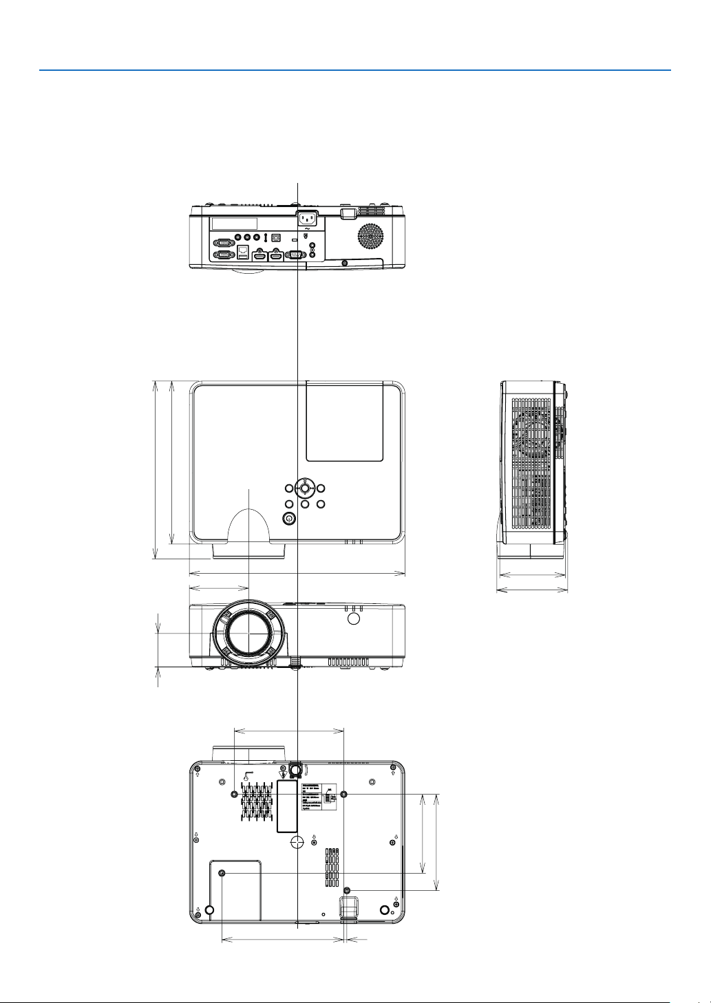
124
9. Appendix
345 (13.6)
284.5 (11.2)
261 (10.3)
113.5 (4.5)
104.6 (4.1)
95 (3.7)
54 (2.1)
175 (6.9)
154 (6.1)
5 (0.2)
195 (7.7)
126.2 (5.0)
❸ Cabinet Dimensions
Unit: mm (inch)
[ME382U/ME342U]
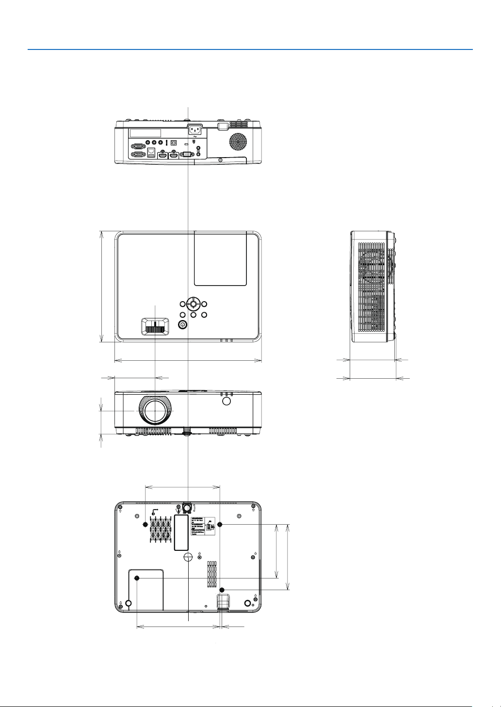
125
9. Appendix
261 (10.3)
345 (13.6)
104.6 (4.1)
108.4 (4.3)
95 (3.7)
54 (2.1)
5 (0.2)
154 (6.1)
126.2 (5.0)
195 (7.7)
175 (6.9)
Unit: mm (inch)
[ME372W/MC382W/MC332W/ME402X/MC422X/MC372X/MC342X/MC302X]
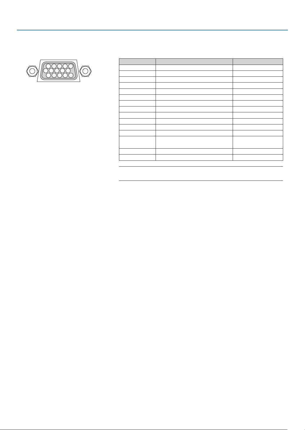
126
9. Appendix
❹ Pin Assignments of D-Sub COMPUTER Input Terminal
Mini D-Sub 15 Pin Terminal
Signal Level
Video signal : 0.7Vp-p (Analog)
Sync signal : TTL level
51 42 3
10
11 12 13 14 15
6 97 8
PinNo.RGBSignal(Analog)YCbCrSignal
1 Red Cr
2 Green or Sync on Green Y
3 Blue Cb
4 Ground
5 Ground
6 Red Ground Cr Ground
7 Green Ground Y Ground
8 Blue Ground Cb Ground
9 Hotplug
10 Sync Signal Ground
11 No Connection
12 Bi-directional DATA (SDA)
13 Horizontal Sync or Composite
Sync
14 Vertical Sync
15 Data Clock
COMPUTERIN
NOTE:PinNos.12and15arerequiredforDDC/CI.
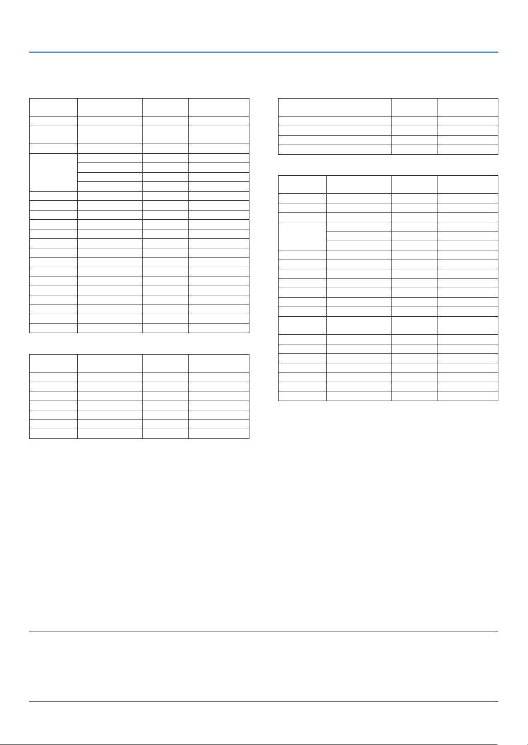
127
9. Appendix
❺ Compatible Input Signal List
AnalogRGB
Signal
Resolution
( dots )
Aspect Ratio
Refresh Rate
( Hz )
VGA 640 × 480 4:3 60/72/75/85/iMac
SVGA 800 × 600 4:3 56/60/72/75/85/
iMac
XGA 1024 × 768 *
1
4:3 60/70/75/85/iMac
WXGA 1280 × 768 *
2
15:9 60
1280 × 800 *
2
16:10 60
1360 × 768 *
3
16:9 60
1366 × 768 *
3
16:9 60
Quad-VGA 1280 × 960 4:3 60/75
SXGA 1280 × 1024 5:4 60/75
SXGA+1400 × 1050 4:3 60
WXGA+1440 × 900 16:10 60
WXGA++1600 × 900 *
3
16:9 60
UXGA 1600 × 1200 *
4
4:3 60
WSXGA+1680 × 1050 16:10 60
HD 1280 × 720 16:9 60
Full HD 1920 × 1080 16:9 60
WUXGA 1920 × 1200 *
5
*
6
16:10 60
MAC 13" 640 × 480 4:3 67
MAC 16" 832 × 624 4:3 75
MAC 19" 1024 × 768 4:3 75
MAC 21" 1152 × 870 4:3 75
MAC 23" 1280 × 1024 5:4 65
Component
Signal Format Aspect Ratio
Refresh Rate
( Hz )
HDTV (1080p) 1920 × 1080 16:9 50/60
HDTV (1080i) 1920 × 1080 16:9 50/60
HDTV (720p) 1280 × 720 16:9 50/60
SDTV (480p) 720 × 480 4:3/16:9 60
SDTV (576p) 720 × 576 4:3/16:9 50
SDTV (480i) 720 × 480 4:3/16:9 60
SDTV (576i) 720 × 576 4:3/16:9 50
NOTE:
•Animagewithhigherorlowerresolutionthantheprojector’snativeresolution(ME402X/MC422X/MC372X/MC342X/MC302X:1024×768/
ME372W/MC382W/MC332W:1280×800/ME382U/ME342U:1920×1200)willbedisplayedwithAdvancedAccuBlend.
•SynconGreenandCompositesyncsignalsarenotsupported.
•Signalsotherthanthosespeciedinthetableabovemaynotbedisplayedcorrectly.Ifthisshouldhappen,changetherefreshrateor
resolutiononyourPC.RefertoDisplayPropertieshelpsectionofyourPCforprocedures.
CompositeVideo
Signal Aspect Ratio
Refresh Rate
( Hz )
NTSC 4:3 60
PAL 4:3 50
PAL60 4:3 60
SECAM 4:3 50
HDMI
Signal
Resolution
( dots )
Aspect Ratio
Refresh Rate
( Hz )
VGA 640 × 480 4:3 60
SVGA 800 × 600 4:3 60
XGA 1024 × 768 *
1
4:3 60
WXGA 1280 × 768 *
2
15:9 60
1280 × 800 *
2
16:10 60
1366 × 768 16:9 60
Quad-VGA 1280 × 960 4:3 60
SXGA 1280 × 1024 5:4 60
SXGA+1400 × 1050 4:3 60
WXGA+1440 × 900 16:10 60
WXGA++1600 × 900 16:9 60
WSXGA+1680 × 1050 16:10 60
WUXGA 1920 × 1200 16:10 60*
7
4K 3840 × 2160 16:9
23.98/24/25/
29.97/30
HDTV (1080p) 1920 × 1080 16:9 50/60
HDTV (1080i) 1920 × 1080 16:9 50/60
HDTV (720p) 1280 × 720 16:9 50/60
SDTV (480p) 720 × 480 4:3/16:9 60
SDTV (576p) 720 × 576 4:3/16:9 50
SDTV(480i) 720 × 480 4:3/16:9 60
SDTV(576i) 720 × 576 4:3/16:9 50
*1 Native resolution on XGA model (ME402X/MC422X/MC372X/
MC342X/MC302X)
*2 Native resolution on WXGA model (ME372W/MC382W/MC332W)
*3 The projector may fail to display these signals correctly when [AUTO]
is selected for [ASPECT RATIO] in the on-screen menu.
The factory default is [AUTO] for [ASPECT RATIO]. To display these
signals, select [16:9] for [ASPECT RATIO].
*4 WXGA MODE: OFF
*5 WXGA MODE: ON
*6 Native resolution on WUXGA model (ME382U/ME342U)
*7 RB (Reduced blanking signal) is effective up to 154MHz.
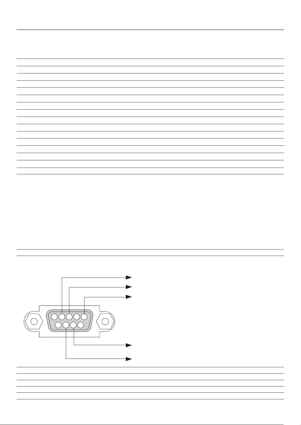
128
9. Appendix
❻ PC Control Codes and Cable Connection
PC Control Codes
Function Code Data
POWER ON 02H 00H 00H 00H 00H 02H
POWER OFF 02H 01H 00H 00H 00H 03H
INPUT SELECT COMPUTER 02H 03H 00H 00H 02H 01H 01H 09H
INPUT SELECT HDMI1 02H 03H 00H 00H 02H 01H 1AH 22H
INPUT SELECT HDMI2 02H 03H 00H 00H 02H 01H 1BH 23H
INPUT SELECT VIDEO 02H 03H 00H 00H 02H 01H 06H 0EH
INPUT SELECT USB-A 02H 03H 00H 00H 02H 01H 1FH 27H
INPUT SELECT LAN 02H 03H 00H 00H 02H 01H 20H 28H
INPUT SELECT USB-B 02H 03H 00H 00H 02H 01H 22H 2AH
PICTURE MUTE ON 02H 10H 00H 00H 00H 12H
PICTURE MUTE OFF 02H 11H 00H 00H 00H 13H
SOUND MUTE ON 02H 12H 00H 00H 00H 14H
SOUND MUTE OFF 02H 13H 00H 00H 00H 15H
NOTE:ContactyourlocaldealerforafulllistofthePCControlCodesifneeded.
Cable Connection
Communication Protocol
Baud rate ������������������������������������������� 38400 bps
Data length ���������������������������������������� 8 bits
Parity �������������������������������������������������No parity
Stop bit ���������������������������������������������� One bit
X on/off ���������������������������������������������� None
Communications procedure ���������������� Full duplex
NOTE:Dependingontheequipment,alowerbaudratemayberecommendedforlongcableruns.
PC Control Terminal (D-SUB 9P)
NOTE1:Pins1,4,6and9arenoused.
NOTE2:Jumper“RequesttoSend”and“CleartoSend”togetheronbothendsofthecabletosimplifycableconnection.
NOTE3:Forlongcablerunsitisrecommendedtosetcommunicationspeedwithinprojectormenusto9600bps.
15243
67 98
ToGNDofPC
ToRxDofPC
ToTxDofPC
ToRTSofPC
ToCTSofPC
129
9. Appendix
ABOUT THE ASCII CONTROL COMMAND
This device supports the common ASCII Control Command for controlling our projector and monitor.
Please visit our web site for detailed information about the command.
https://www.nec-display.com/dl/en/pj_manual/lineup.html
HOWTOCONNECTWITHANEXTERNALDEVICE
There are two methods to connect the projector with an external device such as a computer.
1. Connection thru the serial port.
Connects the projector to a computer by a serial cable (a cross cable).
2. Connection via network (LAN)
Connects the projector to a computer by a LAN cable.
Concerning to the type of LAN cable, please ask to your network administrator.
CONNECTIONINTERFACE
1. Connection thru the serial port.
Communication Protocol
Item Information
Baud rate 38400/19200/9600/4800 bps
Data length 8 bits
Parity bit No parity
Stop bit 1 bit
Flow control None
Communications procedure Full duplex
2. Connection via network
Communication Protocol (Connection via LAN)
Item Information
Communication speed Set automatically (10/100 Mbps)
Supported standard IEEE802.3 (10BASE-T)
IEEE802.3u (100BASE-TX, Auto-Negotiation)
Use the TCP port number 7142 for transmitting and receiving command.
PARAMETERSFORTHISDEVICE
Inputcommand
Input terminal Response Parameter
HDMI1 HDMI1 hdmi1
HDMI2 HDMI2 hdmi2
COMPUTER COMPUTER computer1, computer, rgb, rgb1, vga, vga1
VIDEO VIDEO video
USB-A USB-A usb-a
USB-B USB-B usb-b
LAN LAN lan
Statuscommand
Response Error Status
error:temp Temperature error
error:fan Fan trouble
error:light Light source trouble
error:lens Lens trouble
error:system System trouble
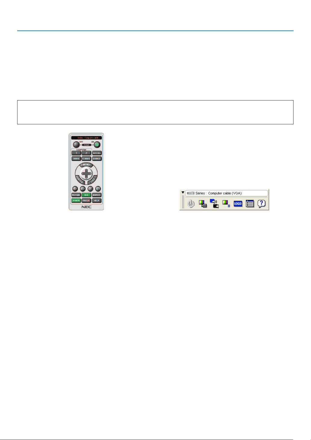
130
9. Appendix
❼ Using the Computer Cable (VGA) to Operate the Projector
(Virtual Remote Tool)
Using the utility software “Virtual Remote Tool” that is available to download from our web site, Virtual Remote screen
(or toolbar) can be displayed on your computer screen.
This will help you perform operations such as projector’s power on or off and signal selection via the computer
cable (VGA), serial cable, or LAN connection. Only via serial or LAN connection it is also used to send an image to
the projector and register it as the logo data of the projector. After registering it, you can lock the logo to prevent it
from changing.
ControlFunctions
Power On/Off, signal selection, picture freeze, picture mute, audio mute, Logo transfer to the projector, and
remote control operation on your PC.
Virtual Remote screen Toolbar
For getting the Virtual Remote Tool, please visit our web site and download it:
https://www.nec-display.com/dl/en/index.html

131
9. Appendix
NOTE:
•When[COMPUTER]isselectedfromyoursourceselection,theVirtualRemotescreenorthetoolbarwillbedisplayedaswellasyour
computer screen.
•Usethesuppliedcomputercable(VGA)toconnecttheCOMPUTERINterminaldirectlywiththemonitoroutputterminalofthecomputer
touseVirtualRemoteTool.
Usingaswitcherorothercablesthanthesuppliedcomputercable(VGA)maycausefailureinsignalcommunication.
VGAcableterminal:
PinNos.12and15arerequiredforDDC/CI.
•VirtualRemoteToolmaynotworkdependingonyourcomputer’sspecicationsandversionofgraphicadaptersordrivers.
•TorunVirtualRemoteTool,“Microsoft.NETFrameworkVersion2.0”isrequired.TheMicrosoft.NETFrameworkVersion2.0,3.0or3.5is
availablefromMicrosoft’swebpage.Downloadandinstallitonyourcomputer.
•Logodata(graphics)thatcanbesenttotheprojectorwithVirtualRemoteToolhasthefollowingrestrictions:
(OnlyviaserialorLANconnection)
-Filesize:Lessthan1MB
-Imagesize(resolution):
ME382U/ME342U:Horizontal1920×vertical1200dotsorless
ME372W/MC382W/MC332W:Horizontal1280×vertical800dotsorless
ME402X/MC422X/MC372X/MC342X/MC302X:Horizontal1024×vertical768dotsorless
-Numberofcolors:256colorsorless
•Toputthedefault"NEClogo"backinthebackgroundlogo,youneedtoregisteritasthebackgroundlogobyusingtheimagele
(ME382U/ME342U:/Logo/necpj_bbwux.bmp,ME372W/MC382W/MC332W:/Logo/necpj_bbwx.bmp,ME402X/MC422X/MC372X/MC342X/
MC302X:/Logo/necpj_bb_x.bmp)incluldedonthesuppliedNECProjectorCD-ROM.
TIP:
•VirtualRemoteToolcanbeusedwithaLANandaserialconnection.USBconnectionisnotsupportedbyVirtualRemoteTool.
•Theprojector’sCOMPUTERINterminalsupportsDDC/CI(DisplayDataChannelCommandInterface).DDC/CIisastandardinterfacefor
bidirectionalcommunicationbetweendisplay/projectorandcomputer.
132
9. Appendix
❽ Troubleshooting Check List
Before contacting your dealer or service personnel, check the following list to be sure repairs are needed also by
referring to the “Troubleshooting” section in your user’s manual. This checklist below will help us solve your problem
more efficiently.
* Print this page and the next page for your check.
Frequency of occurrence □ always □ sometimes (How often?_____________________) □ other (__________________)
Power
□
No power (POWER indicator does not light blue) See also “Status
Indicator (STATUS)”�
□
Power cord’s plug is fully inserted into the wall outlet�
□
Main power switch is pressed to the ON position�
□
Lamp cover is installed correctly�
□
Lamp Hours Used (lamp operation hours) was cleared after lamp
replacement�
□
No power even though you press and hold the POWER button�
□
Shut down during operation�
□
Power cord’s plug is fully inserted into the wall outlet�
□
Lamp cover is installed correctly�
□
[AUTO POWER OFF] is turned off (only models with the [AUTO
POWER OFF] function)�
□
[OFF TIMER] is turned off (only models with the [OFF TIMER]
function)�
Video and Audio
□
No image is displayed from your PC or video equipment to the projector�
□
Still no image even though you connect the projector to the PC
first, then start the PC�
□
Enabling your notebook PC’s signal output to the projector�
•Acombinationoffunctionkeyswillenable/disabletheexternal
display.Usually,thecombinationofthe“Fn”keyalongwithone
ofthe12functionkeysturnstheexternaldisplayonoroff.
□
No image (blue or black background, no display)�
□
Still no image even though you press the AUTO ADJUST button�
□
Still no image even though you carry out [RESET] in the
projector’s menu�
□
Signal cable’s plug is fully inserted into the input terminal�
□
A message appears on the screen�
( _____________________________________________ )
□
The source connected to the projector is active and available�
□
Still no image even though you adjust the brightness and/or the
contrast�
□
Input source’s resolution and frequency are supported by the
projector�
□
Image is too dark�
□
Remains unchanged even though you adjust the brightness and/
or the contrast�
□
Image is distorted�
□
Image appears to be trapezoidal (unchanged even though you carry
out the [KEYSTONE] adjustment)�
□
Parts of the image are lost�
□
Still unchanged even though you press the AUTO ADJUST button�
□
Still unchanged even though you carry out [RESET] in the
projector’s menu�
□
Image is shifted in the vertical or horizontal direction�
□
Horizontal and vertical positions are correctly adjusted on a
computer signal�
□
Input source’s resolution and frequency are supported by the
projector�
□
Some pixels are lost�
□
Image is flickering�
□
Still unchanged even though you press the AUTO ADJUST button�
□
Still unchanged even though you carry out [RESET] in the
projector’s menu�
□
Image shows flickering or color drift on a computer signal�
□
Still unchanged even though you change [FAN MODE] from [HIGH
ALTITUDE] to [AUTO]�
□
Image appears blurry or out of focus�
□
Still unchanged even though you checked the signal’s resolution
on PC and changed it to projector’s native resolution�
□
Still unchanged even though you adjusted the focus�
□
No sound�
□
Audio cable is correctly connected to the audio input of the projector�
□
Still unchanged even though you adjusted the volume level�
□
AUDIO OUT is connected to your audio equipment (only models with
the AUDIO OUT terminal)�
Other
□
Remote control does not work�
□
No obstacles between the sensor of the projector and the remote
control�
□
Projector is placed near a fluorescent light that can disturb the
infrared remote controls�
□
Batteries are new and are not reversed in installation�
□
Buttons on the projector cabinet do not work (only models with the
[CONTROL PANEL LOCK] function)
□
[CONTROL PANEL LOCK] is not turned on or is disabled in the menu�
□
Still unchanged even though you press and hold the INPUT button
for a minimum of 10 seconds�
133
9. Appendix
In the space below please describe your problem in detail.
Information on application and environment where your projector is used
Projector
PC
DVD player
Projector
Model number:
Serial No�:
Date of purchase:
Lamp operating time (hours):
Eco Mode: □ OFF □ AUTO ECO
□ NORMAL □ ECO
Information on input signal:
Horizontal synch frequency [ ] kHz
Vertical synch frequency [ ] Hz
Synch polarity H □ (+) □ (−)
V □ (+) □ (−)
Synch type □ Separate □ Composite
□ Sync on Green
Indicator Message:
□ POWER
Blinks in □ Blue □ Green □ Orange □ Red
[ ] cycles
Lights in □ Blue □ Green □ Orange □ Red
□ STATUS
Blinks in □ Blue □ Green □ Orange □ Red
[ ] cycles
Lights in □ Blue □ Green □ Orange □ Red
□ LAMP
Blinks in □ Blue □ Green □ Orange □ Red
[ ] cycles
Lights in □ Blue □ Green □ Orange □ Red
Remote control model number:
Installationenvironment
Screen size: inch
Screen type: □ White matte □ Beads □ Polarization
□ Wide angle □ High contrast
Throw distance: feet/inch/m
Orientation: □ Ceiling mount □ Desktop
Power outlet connection:
□ Connected directly to wall outlet
□ Connected to power cord extender or other (the number
of connected equipment______________)
□ Connected to a power cord reel or other (the number of
connected equipment______________)
Computer
Manufacturer:
Model number:
Notebook PC □ / Desktop □
Native resolution:
Refresh rate:
Video adapter:
Other:
Videoequipment
VCR, DVD player, Video camera, Video game or other
Manufacturer:
Model number:
Signalcable
NEC standard or other manufacturer’s cable?
Model number: Length: inch/m
Distribution amplifier
Model number:
Switcher
Model number:
Adapter
Model number:

134
9. Appendix
❾ REGISTER YOUR PROJECTOR! (for residents in the United
States, Canada, and Mexico)
Please take time to register your new projector. This will activate your limited parts and labor warranty and InstaCare
service program.
Visit our web site at www.necdisplay.com, click on support center/register product and submit your completed
form online.
Upon receipt, we will send a confirmation letter with all the details you will need to take advantage of fast, reliable
warranty and service programs from the industry leader, NEC Display Solutions of America, Inc.

© NEC Display Solutions, Ltd. 2018 7N952821