
Loading ...
Loading ...
Loading ...
Unit Side
(Field-Supplied)
Insulating Pipe
(Field-Supplied)
Cord Clamp
(Factory-Supplied)
Insulating Pipe
(Field-Supplied)
Refrigeration Piping
Fig. 5.1 Pipe Connection Points
Fig. 5.2 Pipe Diameter
Since the nut cap connected at gas pipe is
designed exclusively for R410A, the piping flaring
connected for off-factory installation is adjusted as
compared with R22 and R407C. Please perform
the processing operation based on the dimensions
shown below: (See Fig. 5.3)
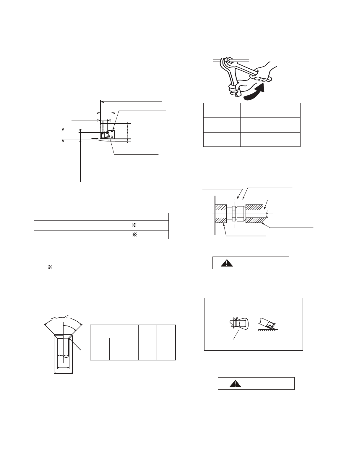
(2) As shown in Fig. 5.4, two spanners shall be used for
Insulating Pipe
Cap the end of the pipe when the pipe is to
penetrate a hole.
Do not put pipes on the ground directly without a
cap or vinyl tape arranged at the end of the pipe.
Do not put pipes on the ground directly
Correct
Incorrect
Blocked with Tape or Plug
(4) Discharging and Charging Refrigerant
Follow the Installation & Maintenance Manual for
outdoor unit.
Excessive and inadequate refrigerant is a leading
cause of system anomaly.
Please inject the right amount of refrigerant.
Pipe Size.(mm)
TighteningTorque ft·(N.m)
10.3~13.3(14~)
29.5(40)
44.3(60)
48.7~56.8(63~77)
Outside Diameter of
Piping (a)
Outside
Diameter
of Flaring
(D)
R410A
21/32
(16.6)
25/32
(19.7)
Unit: in. (mm)
1/2
5/8
(Φ12.7)
(Φ15.88)
Fig. 5.3 Flaring
5.2 Piping Connection
Fig. 5.4 Nut tightening torque
(3) Insulate the refrigeration piping with field-
supplied insulating pipe upon completion of
refrigerant pipe connection. See Fig. 5.5.
Fig. 5.5 Insulation on Pipes
90
0
±2
0
45
0
R0.4~0.8
a
D
0
-0.4
±2
0
●
●
(1) The connection point and diameter of piping
are shown in Figs. 5.1 and 5.2.
Unit: in.(mm)
73.8(100)
5
Gas Pipe
Liquid Pipe
Capacity of indoor unit(kBtu/h)
1/2(Φ12.7)
5/8(Φ15.88)
1/4(Φ6.35)
3/8(Φ9.53)
09~22
24~54
R22、R407C
41/64
(16.2)
49/64
(19.4)
5-29/32(150) (Connected to
Gas Pipe)
6-37/64(167) (Connected to
Liquid Pipe)
33-5/64(0) ( )
6-19/64(160) (Liquid Pipe)
3-47/64(9) (Gas Pipe)
5/8(Φ15.88)
1/2(Φ12.7)
3/8(Φ9.53)
1/4(Φ6.35)
3/4(Φ19.05)
Unit: in.(mm)
Loading ...
Loading ...
Loading ...