OPERATOR'S MANUAL
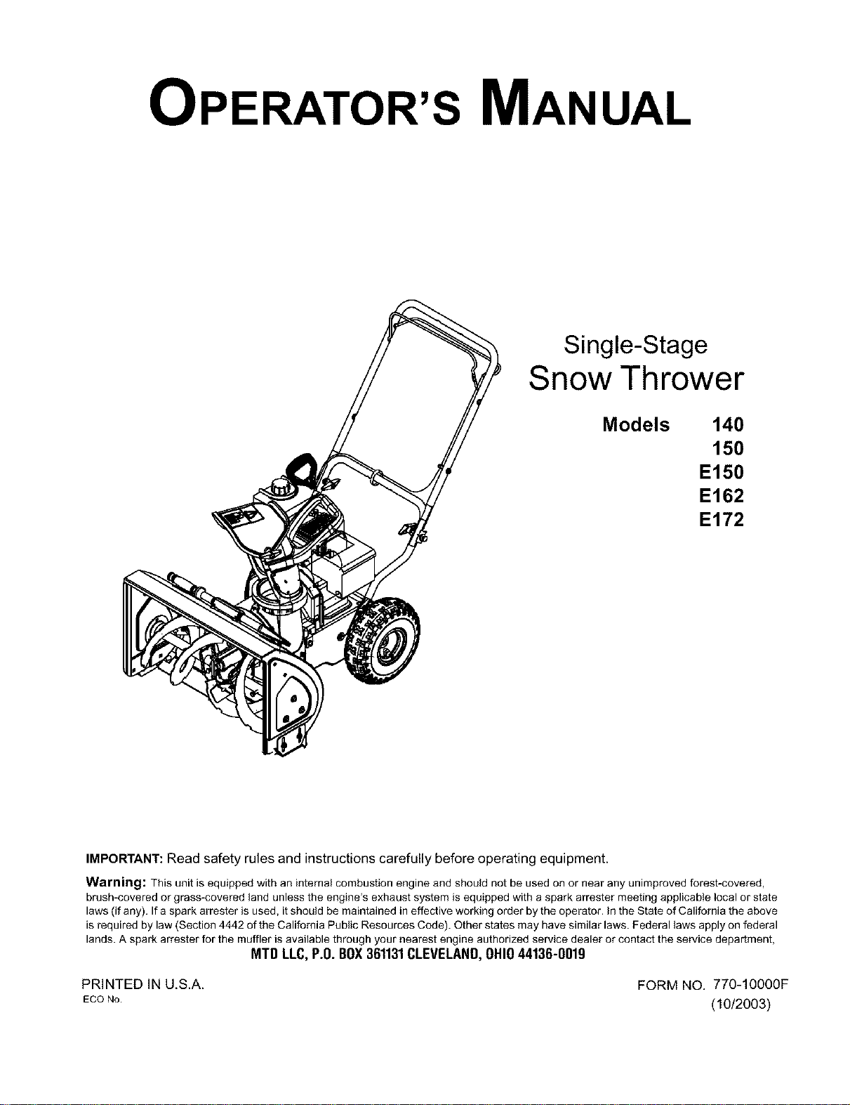
Single-Stage
Snow Thrower
Models 140
150
E150
E162
E172
IMPORTANT:Read safety rules and instructionscarefully before operating equipment.
Warning: This unit is equipped with an internal combustion engine and should not be used on or near any unimproved forest-covered,
brush-covered or grass-covered land unless the engine's exhaust system is equipped with a spark attester meeting applicable local or state
laws (if any). If a spark arrester is used, it should be maintained in effective working order by the operator. In the State of California the above
is required by law (Section 4442 of the California Public Resources Code). Other states may have similar laws. Federal laws apply on federal
lands. A spark attester for the muffler is available through your nearest engine authodzed service dealer or contact the service department,
MTD LLC, P.O.BOX361131CLEVELAND,OHIO44136-0019
PRINTED IN U.S.A. FORM NO. 770-10000F
ECONo. (10/2003)
TABLEOFCONTENTS
Content Page
Important Safe Operation Practices ......................................................................................... 3
Assembling Your Snow Thrower .............................................................................................. 5
Know Your Snow Thrower ........................................................................................................ 7
Operating Your Snow Thrower ................................................................................................. 8
Making Adjustments ................................................................................................................. 9
Maintaining Your Snow Thrower .............................................................................................. 10
Off-Season Storage ................................................................................................................. 11
Troubleshooting ....................................................................................................................... 11
Accessories & Kits ................................................................................................................... 12
Parts List .................................................................................................................................. 14
FINDINGMODELNUMBER
This Operator's Manual is an important part of your new snow thrower. It will help you to assemble, prepare and
maintain the unit for best performance. Please read and understand what it says.
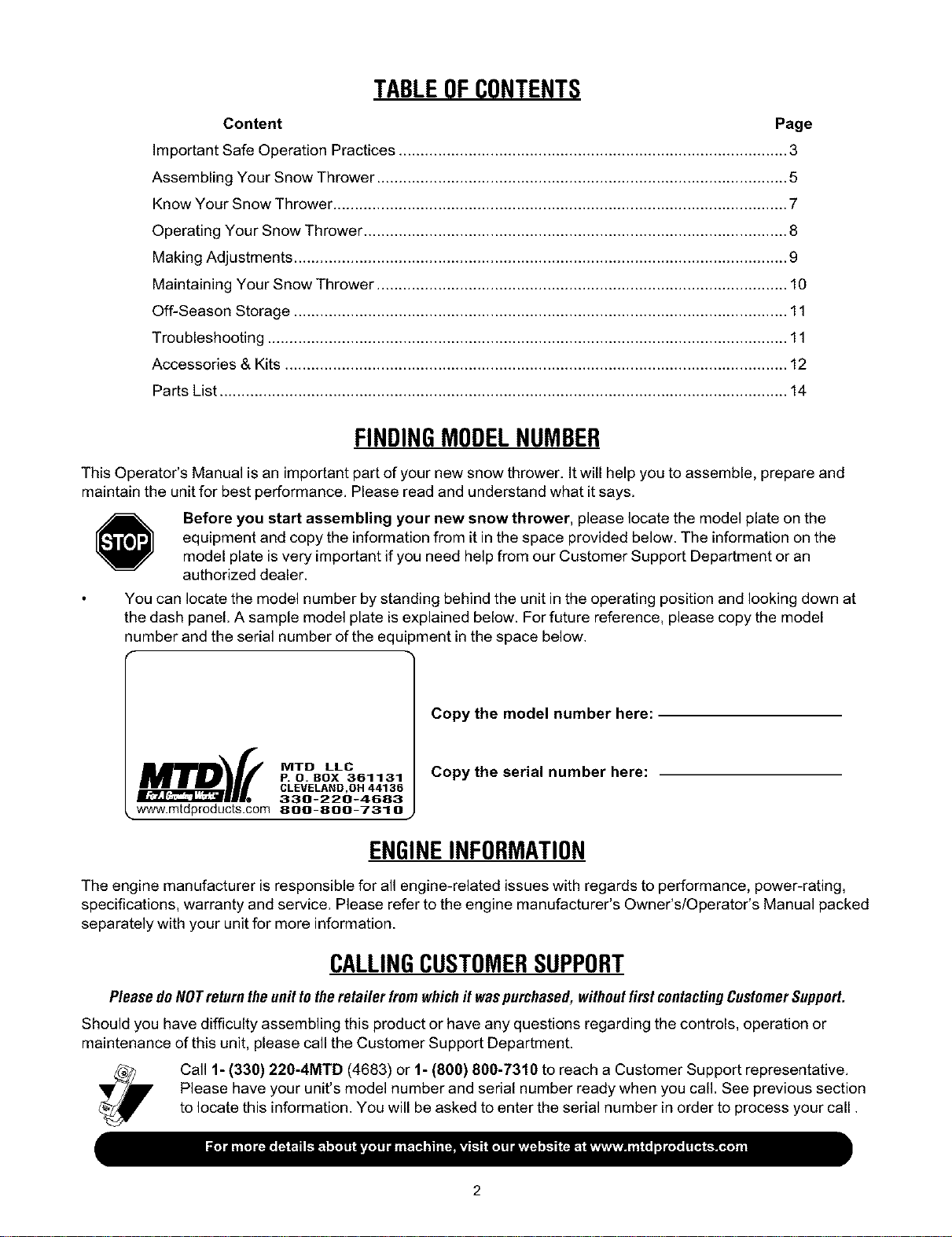
Before you start assembling your new snow thrower, please locate the model plate on the
equipment and copy the information from it inthe space provided below. The information on the
model plate is very important if you need help from our Customer Support Department or an
authorized dealer.
You can locate the model number by standing behind the unit in the operating position and looking down at
the dash panel. A sample model plate is explained below. For future reference, please copy the model
number and the serial number of the equipment in the space below.
Copy the model number here:
o.o,,°
P. O. BOX 361131
CLEVELAND ,OH 44136
330-220-4683
• www.mtdproducts.com 800-800-7310
Copy the serial number here:
ENGINEINFORMATION
The engine manufacturer is responsible for all engine-related issues with regards to performance, power-rating,
specifications, warranty and service. Please refer to the engine manufacturer's Owner's/Operator's Manual packed
separately with your unit for more information.
CALLINGCUSTOMERSUPPORT
PleasedoNOTreturntheun# totheretailer from which# waspurchased,withoutfirstcontactingCustomerSupport.
Should you have difficulty assembling this product or have any questions regarding the controls, operation or
maintenance of this unit, please call the Customer Support Department.
Call 1- (330) 220-4MTD (4683) or 1- (800) 800-7310 to reach a Customer Support representative.
Please have your unit's model number and serial number ready when you call. See previous section
to locate this information. You will be asked to enter the serial number in order to process your call.
SECTION1: IMPORTANTSAFEOPERATIONPRACTICES
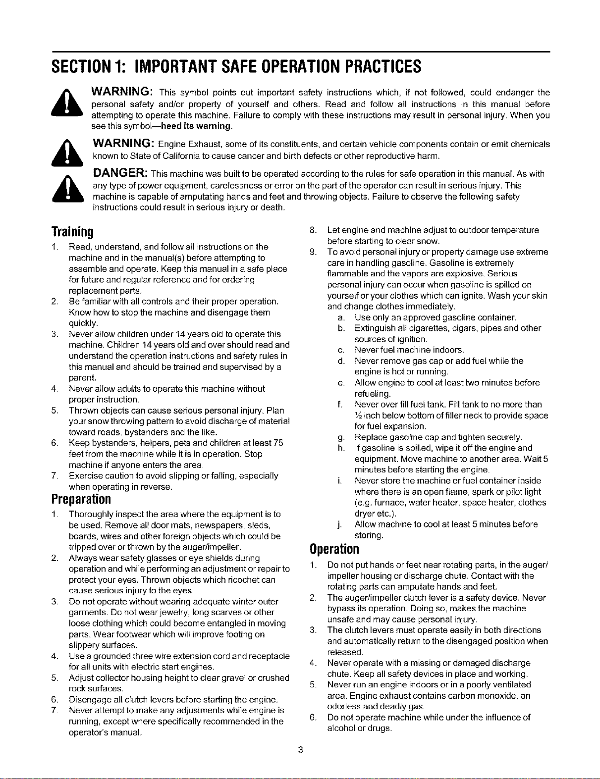
WARNING: This symbol points out important safety instructions which, if not followed, could endanger the
personal safety and/or property of yourself and others. Read and follow all instructions in this manual before
attempting to operate this machine. Failure to comply with these instructions may result in personal injury. When you
see this symbol--heed its warning.
WARNING: Engine Exhaust, some of its constituents, and certain vehicle components contain or emit chemicals
known to State of California to cause cancer and birth defects or other reproductive harm.
DANGER: This machine was built to be operated according to the rules for safe operation in this manual. As with
any type of power equipment, carelessness or error on the part of the operator can result in serious injury. This
machine is capable of amputating hands and feet and throwing objects. Failure to observe the following safety
instructions could result in serious injury or death.
Training
1. Read, understand, and follow all instructions on the
machine and in the manual(s) before attempting to
assemble and operate. Keep this manual in a safe place
for future and regular reference and for ordering
replacement parts.
2. Be familiar with all controls and their proper operation.
Know how to stop the machine and disengage them
quickly.
3. Never allow children under 14 years old to operate this
machine. Children 14years old and over should read and
understand the operation instructions and safety rules in
this manual and should be trained and supervised by a
parent.
4. Never allow adults to operate this machine without
proper instruction.
5. Thrown objects can cause serious personal injury. Plan
your snow throwing pattern to avoid discharge of material
toward roads, bystanders and the like.
6. Keep bystanders, helpers, pets and children at least 75
feet from the machine while it is in operation. Stop
machine if anyone enters the area.
7. Exercise caution to avoid slipping or falling, especially
when operating in reverse.
Preparation
1. Thoroughly inspect the area where the equipment is to
be used. Remove all door mats, newspapers, sleds,
boards, wires and other foreign objects which could be
tripped over or thrown by the auger/impeller.
2. Always wear safety glasses or eye shields during
operation and while performing an adjustment or repair to
protect your eyes. Thrown objects which ricochet can
cause serious injury to the eyes.
3. Do not operate without wearing adequate winter outer
garments. Do not wear jewelry, long scarves or other
loose clothing which could become entangled in moving
parts. Wear footwear which will improve footing on
slippery surfaces.
4. Use a grounded three wire extension cord and receptacle
for all units with electric start engines.
5. Adjust collector housing height to clear gravel or crushed
rock surfaces.
6. Disengage all clutch levers before starting the engine.
7. Never attempt to make any adjustments while engine is
running, except where specifically recommended in the
operator's manual.
8. Let engine and machine adjust to outdoor temperature
before starting to clear snow.
9. To avoid personal injury or property damage use extreme
care in handling gasoline. Gasoline is extremely
flammable and the vapors are explosive. Serious
personal injury can occur when gasoline is spilled on
yourself or your clothes which can ignite. Wash your skin
and change clothes immediately.
a. Use only an approved gasoline container.
b. Extinguish all cigarettes, cigars, pipes and other
sources of ignition.
c. Never fuel machine indoors.
d. Never remove gas cap or add fuel while the
engine is hot or running.
e. Allow engine to cool at least two minutes before
refueling.
f. Never over fill fuel tank. Fill tank to no more than
½ inch below bottom of filler neck to provide space
for fuel expansion.
g. Replace gasoline cap and tighten securely.
h. If gasoline is spilled, wipe it off the engine and
equipment. Move machine to another area. Wait 5
minutes before starting the engine.
Never store the machine or fuel container inside
where there is an open flame, spark or pilot light
(e.g. furnace, water heater, space heater, clothes
dryer etc.).
Allow machine to cool at least 5 minutes before
storing.
Operation
1. Do not put hands or feet near rotating parts, in the auger/
impeller housing or discharge chute. Contact with the
rotating parts can amputate hands and feet.
2. The auger/impeller clutch lever is a safety device. Never
bypass its operation. Doing so, makes the machine
unsafe and may cause personal injury.
3. The clutch levers must operate easily in both directions
and automatically return to the disengaged position when
released.
4. Never operate with a missing or damaged discharge
chute. Keep all safety devices in place and working.
5. Never run an engine indoors or in a poorly ventilated
area. Engine exhaust contains carbon monoxide, an
odorless and deadly gas.
6. Do not operate machine while under the influence of
alcohol or drugs.
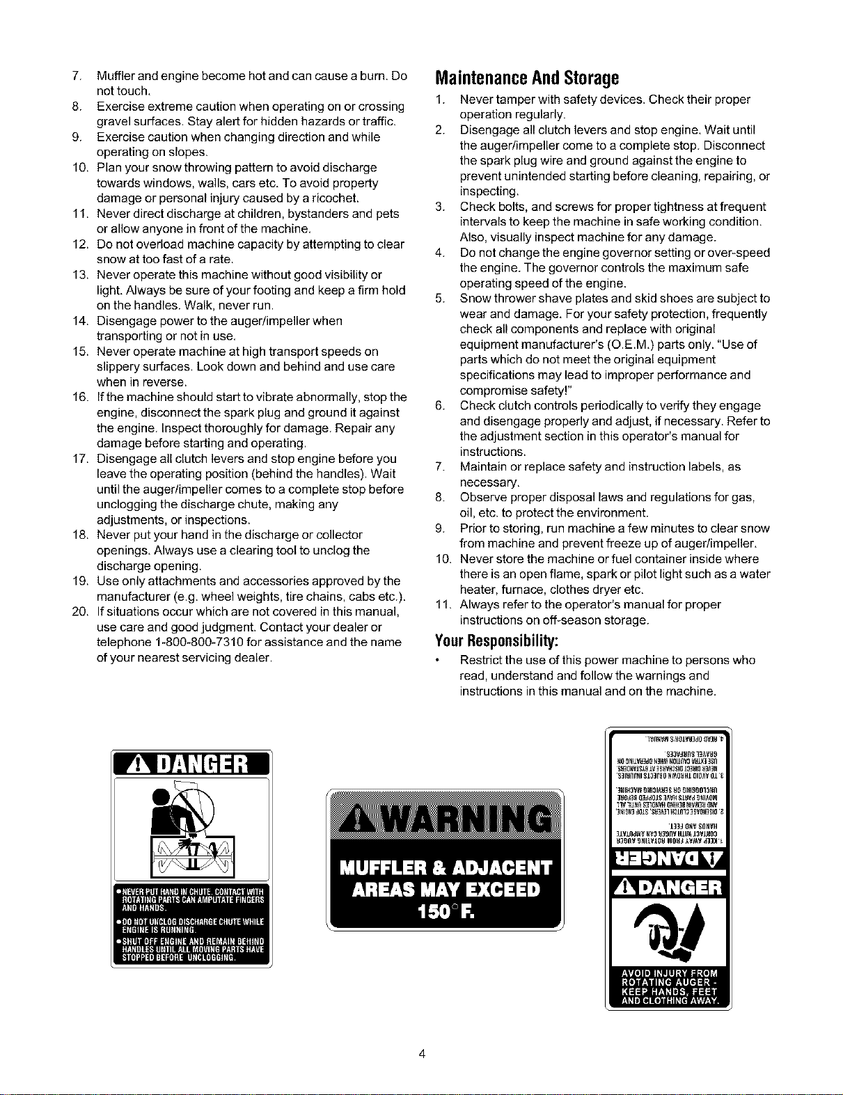
7. Mufflerandenginebecomehotandcancauseaburn.Do
nottouch.
8. Exerciseextremecautionwhenoperatingonorcrossing
gravelsurfaces.Stayalertforhiddenhazardsortraffic.
9. Exercisecautionwhenchangingdirectionandwhile
operatingonslopes.
10.Planyoursnowthrowingpatterntoavoiddischarge
towardswindows,walls,carsetc.Toavoidproperty
damageorpersonalinjurycausedbyaricochet.
11.Neverdirectdischargeatchildren,bystandersandpets
orallowanyoneinfrontofthemachine.
12.Donotoverloadmachinecapacitybyattemptingtoclear
snowattoofastofarate.
13.Neveroperatethismachinewithoutgoodvisibilityor
light.Alwaysbesureofyourfootingandkeepafirmhold
onthehandles.Walk,neverrun.
14.Disengagepowertotheauger/impellerwhen
transportingornotinuse.
15.Neveroperatemachineathightransportspeedson
slipperysurfaces.Lookdownandbehindandusecare
wheninreverse.
16.Ifthemachineshouldstarttovibrateabnormally,stopthe
engine,disconnectthesparkplugandgrounditagainst
theengine.Inspectthoroughlyfordamage.Repairany
damagebeforestartingandoperating.
17.Disengageallclutchleversandstopenginebeforeyou
leavetheoperatingposition(behindthehandles).Wait
untiltheauger/impellercomestoacompletestopbefore
uncloggingthedischargechute,makingany
adjustments,orinspections.
18.Neverputyourhandinthedischargeorcollector
openings.Alwaysuseaclearingtooltounclogthe
dischargeopening.
19.Useonlyattachmentsandaccessoriesapprovedbythe
manufacturer(e.g.wheelweights,tirechains,cabsetc.).
20.Ifsituationsoccurwhicharenotcoveredinthismanual,
usecareandgoodjudgment.Contactyourdealeror
telephone1-800-800-7310forassistanceandthename
ofyournearestservicingdealer.
MaintenanceAndStorage
1. Never tamper with safety devices. Check their proper
operation regularly.
2. Disengage all clutch levers and stop engine. Wait until
the auger/impeller come to a complete stop. Disconnect
the spark plug wire and ground against the engine to
prevent unintended starting before cleaning, repairing, or
inspecting.
3. Check bolts, and screws for proper tightness at frequent
intervals to keep the machine in safe working condition.
Also, visually inspect machine for any damage.
4. Do not change the engine governor setting or over-speed
the engine. The governor controls the maximum safe
operating speed of the engine.
5. Snow thrower shave plates and skid shoes are subject to
wear and damage. For your safety protection, frequently
check all components and replace with original
equipment manufacturer's (O.E.M.) parts only. "Use of
parts which do not meet the original equipment
specifications may lead to improper performance and
compromise safety.
6. Check clutch controls periodically to verify they engage
and disengage properly and adjust, if necessary. Refer to
the adjustment section in this operator's manual for
instructions.
7. Maintain or replace safety and instruction labels, as
necessary,
8. Observe proper disposal laws and regulations for gas,
oil, etc. to protect the environment.
9. Prior to storing, run machine a few minutes to clear snow
from machine and prevent freeze up of auger/impeller,
10. Never store the machine or fuel container inside where
there is an open flame, spark or pilot light such as a water
heater, furnace, clothes dryer etc,
11. Always refer to the operator's manual for proper
instructions on off-season storage.
YourResponsibility:
Restrict the use of this power machine to persons who
read, understand and follow the warnings and
instructions inthis manual and on the machine.
lvnNvgJ S,YOIVY]dO OV]_Jt
g]3VJ)lJlg13_V_9
_0_NI1VE3dOE31t__041_V0yEL_3gn
'$]EIIfllNI_13]r90 fll'_O_HIOI[IAVOlI
_HIHOV_ORJOIAU3SUOORJOgO]3_fl
]_O_903ddOIS]AVffSlb_dO_lAOB
llYlUNn $31_H ONIH38_1_3_ _N_
1]_d _ SOHYH
31ylnd_v N_3_39DY HII_ 13VIR03
SECTION2: ASSEMBLINGYOURSNOWTHROWER
NOTE: This Operator's Manual covers several models.
Snow thrower features vary by model. Not all
features discussed in this manual are applicable to all
snow thrower models.
ContentsofCarton
Before beginning installation, remove all parts from the
carton and compare them to Figure 1.Carton contents
are listed below with part numbers in parentheses.
Two Ignition Keys (725-0201, 725-1341B t)
1-An ignitionkey with a plasticcover is includedwith
select models only. Two standard ignitionkeysare
includedwith all other models.
OnModelsSoEquipped:
Extended Chute Directional Control Assembly
(747-0737, 720-0201A & 726-0100)
One Cotter Pin (714-0507)
One Saddle Washer (736-0415)
Two Flex Nuts (712-3010)
One Eye Bolt (747-0697) w/Grommet (735-0234)
Ignition Key w/Plastic Cover t
Standard Ignition Key
-'1 Cotter Pin
_) -,_ Saddle Washer
• • "_ Hex Nuts
_< Eye Bolt
Extended Chute
Directional Control Assembly
Figure 1
NOTE: All references to left or right side of the snow
thrower is from the operating position only.
_, WARNING: Disconnect the spark plug wire
and ground it against the engine to prevent
unintended starting.
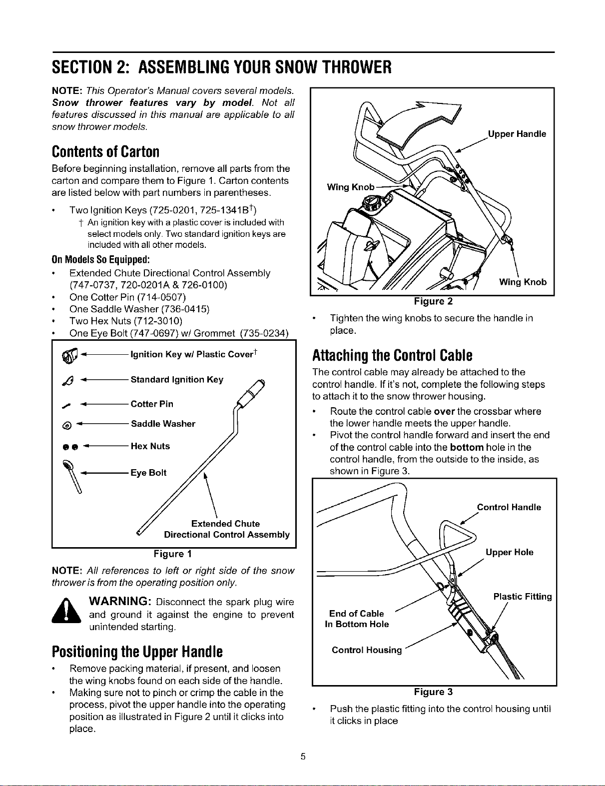
Positioningthe UpperHandle
Remove packing material, if present, and loosen
the wing knobs found on each side of the handle.
Making sure not to pinch or crimp the cable in the
process, pivot the upper handle into the operating
position as illustrated in Figure 2 until it clicks into
place.
Wing
Wing Knob
Figure 2
Tighten the wing knobs to secure the handle in
place.
AttachingtheControlCable
The control cable may already be attached to the
control handle. If it's not, complete the following steps
to attach it to the snow thrower housing.
Route the control cable over the crossbar where
the lower handle meets the upper handle.
Pivot the control handle forward and insert the end
of the control cable into the bottom hole in the
control handle, from the outside to the inside, as
shown in Figure 3.
Control Handle
Upper Hole
End of Cable
In Bottom Hole
Control Housinc
Plastic Fitting
Figure 3
Push the plastic fitting into the control housing until
it clicks in place
NOTE:The upper hole in the control handle provides
for adjustment in belt and cable tension. Refer to page
9 of this manual for instructions.
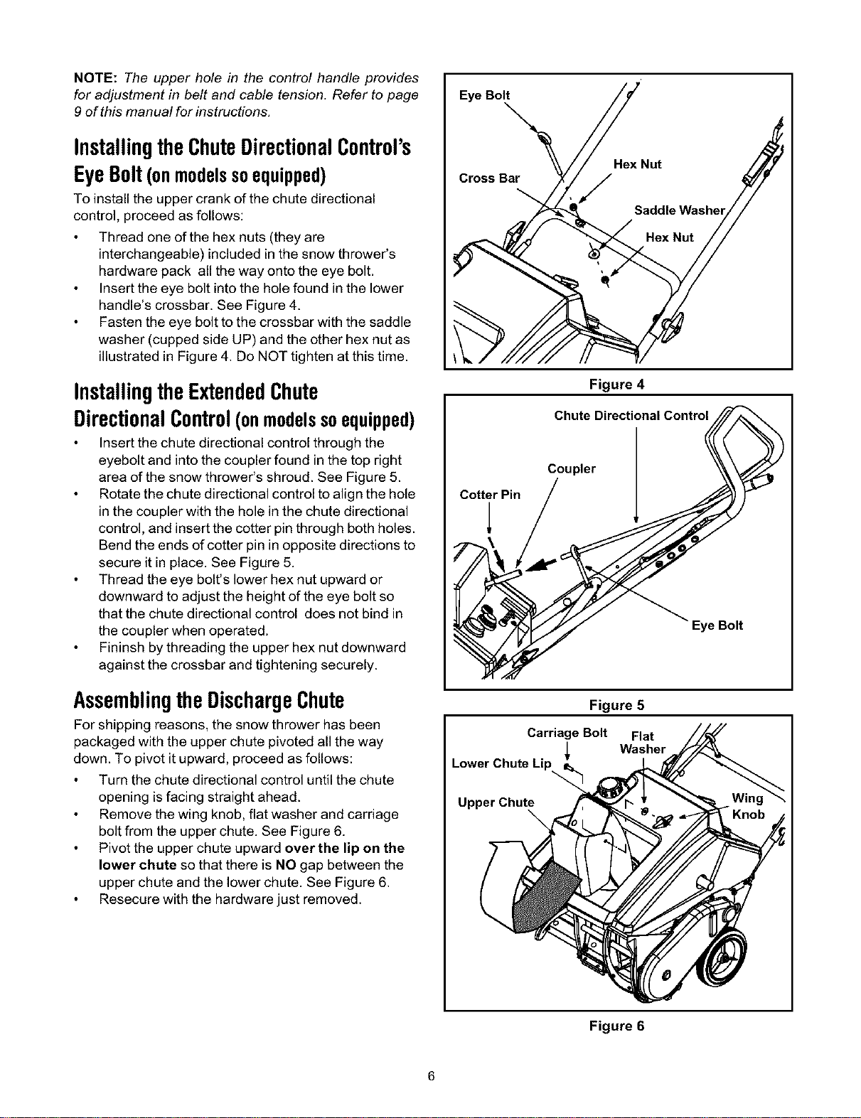
InstallingtheChuteDirectionalControl's
EyeBolt(onmodelssoequipped)
To install the upper crank of the chute directional
control, proceed as follows:
Thread one of the hex nuts (they are
interchangeable) included in the snow thrower's
hardware pack all the way onto the eye bolt.
Insert the eye bolt into the hole found in the lower
handle's crossbar. See Figure 4.
Fasten the eye bolt to the crossbar with the saddle
washer (cupped side UP) and the other hex nut as
illustrated in Figure 4. Do NOT tighten at this time.
InstallingtheExtendedChute
DirectionalControl(onmodelssoequipped)
Insert the chute directional control through the
eyebolt and into the coupler found in the top right
area of the snow thrower's shroud. See Figure 5.
Rotate the chute directional control to align the hole
in the coupler with the hole in the chute directional
control, and insert the cotter pin through both holes.
Bend the ends of cotter pin in opposite directions to
secure it in place. See Figure 5.
Thread the eye bolt's lower hex nut upward or
downward to adjust the height of the eye bolt so
that the chute directional control does not bind in
the coupler when operated.
Fininsh by threading the upper hex nut downward
against the crossbar and tightening securely.
Assemblingthe DischargeChute
For shipping reasons, the snow thrower has been
packaged with the upper chute pivoted all the way
down. To pivot it upward, proceed as follows:
Turn the chute directional control until the chute
opening is facing straight ahead.
Remove the wing knob, flat washer and carriage
bolt from the upper chute. See Figure 6.
Pivot the upper chute upward over the lip on the
lower chute so that there is NO gap between the
upper chute and the lower chute. See Figure 6.
Resecure with the hardware just removed.
Eye Bolt
Cross Bar
Figure 4
CiiltllDirecti°nal C°ntr°I
CotterPin / / 7_' )_
"Eye Bolt
Figure 5
Carriage Bolt Flat
Washer
Lower Chute Lip
Upper Chute
Figure 6
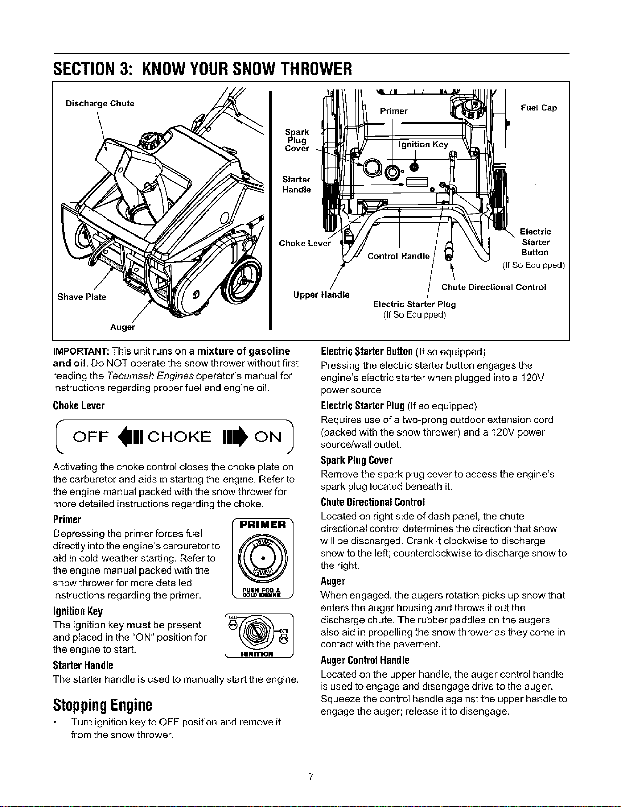
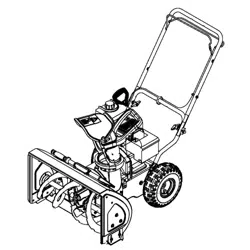
SECTION3: KNOWYOURSNOWTHROWER
Discharge Chute
Shave Plate
Auger
Sp_lark
ug
Cover
Starter
Choke Lever
Upper Handle
Cap
Control Handle
Electric
Starter
Button
(If So Equipped)
Chute Directional Control
Electric Starter Plug
(If So Equipped)
IMPORTANT:This unit runs on a mixture of gasoline
and oil. Do NOT operate the snow thrower without first
reading the Tecumseh Engines operator's manual for
instructions regarding proper fuel and engine oil.
ChokeLever
I OFF III CHOKE Ill ON I
Activating the choke control closes the choke plate on
the carburetor and aids in starting the engine. Refer to
the engine manual packed with the snow thrower for
more detailed instructions regarding the choke.
Primer
Depressing the primer forces fuel
directly into the engine's carburetor to
@
aid in cold-weather starting. Refer to
the engine manual packed with the
snow thrower for more detailed
pUSH FOIl A
instructionsregarding the primer. _=m,.=
IgnitionKey
The ignition key must be present |(_ f//'_"_
and placed in the "ON" position for
the engine to start.
Starter Handle
The starter handle is used to manually start the engine.
StoppingEngine
Turn ignition key to OFF position and remove it
from the snow thrower.
ElectricStarter Button(If so equipped)
Pressing the electric starter button engages the
engine's electric starter when plugged into a 120V
power source
ElectricStarterPlug (If so equipped)
Requires use of atwo-prong outdoor extension cord
(packed with the snow thrower) and a 120V power
source/wall outlet.
SparkPlugCover
Remove the spark plug cover to access the engine's
spark plug located beneath it.
ChuteDirectionalControl
Located on right side of dash panel, the chute
directional control determines the direction that snow
will be discharged. Crank it clockwise to discharge
snow to the left; counterclockwise to discharge snow to
the right.
Auger
When engaged, the augers rotation picks up snow that
enters the auger housing and throws it out the
discharge chute. The rubber paddles on the augers
also aid in propelling the snow thrower as they come in
contact with the pavement.
AugerControlHandle
Located on the upper handle, the auger control handle
is used to engage and disengage drive to the auger.
Squeeze the control handle against the upper handle to
engage the auger; release it to disengage.
Discharge Chute
The pitch of the discharge chute controls the angle at
which the snow is thrown, Loosen the wing knob on the
side of the discharge chute before pivoting the
discharge chute upward or downward. Retighten the
knob once the desired position has been achieved.
ShavePlate
The shave plate scrapes along the pavement as the
snow thrower is propelled, allowing the snow close to
the pavement's surface to be discharged.
SECTION4: OPERATINGYOURSNOWTHROWER
WARNING: Before starting the engine,
read, understand, and follow all instructions
and warnings on the machine and in this
manual before operating.
FuelAndOilMixture
WARNING: Use extreme care when
handling gasoline. Gasoline is extremely
flammable and the vapors are explosive.
Never fuel machine indoors or while the
engine is hot or running. Extinguish cigarettes,
cigars, pipes and other sources of ignition.
Your snow thrower is equipped with a two-cycle
engine that requires a mixture of gasoline and two
cycle engine oil at a ratio of 58:1. Refer to the
Tecumseh Engines operator's manual for detailed
instructions regarding oil and gasoline for your snow
thrower's engine.
A plastic cup is placed inside the fuel fill opening on
the fuel tank (beneath the fuel cap) to keep debris
out during product assembly. Remove and discard
this cup before filling up the tank.
IMPORTANT:Do NOT operate the snow thrower without
the fuel cap securely in place on the fuel tank.
StartingtheEngine
Refer to the Tecumseh Engines manual packed
with the snow thrower for detailed instructions
regarding starting the engine.
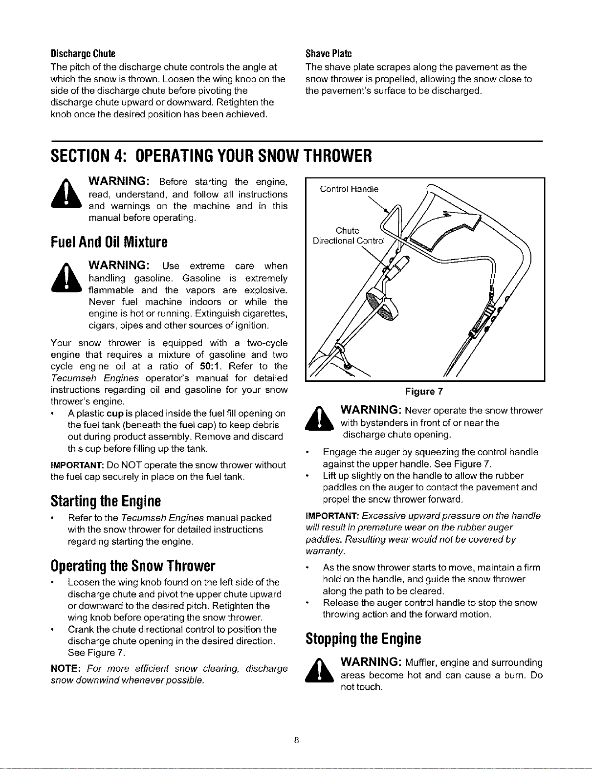
OperatingtheSnowThrower
Loosen the wing knob found on the left side of the
discharge chute and pivot the upper chute upward
or downward to the desired pitch. Retighten the
wing knob before operating the snow thrower.
Crank the chute directional control to position the
discharge chute opening in the desired direction.
See Figure 7.
NOTE: For more efficient snow clearing, discharge
snow downwind whenever possible.
Control Handle
Chute
Figure 7
,_ WARNING: Never operate the snow thrower
with bystanders in front of or near the
discharge chute opening.
Engage the auger by squeezing the control handle
against the upper handle. See Figure 7.
Lift up slightly on the handle to allow the rubber
paddles on the auger to contact the pavement and
propel the snow thrower forward.
IMPORTANT:Excessive upward pressure on the handle
will result in premature wear on the rubber auger
paddles. Resulting wear would not be covered by
warranty.
As the snow thrower starts to move, maintain a firm
hold on the handle, and guide the snow thrower
along the path to be cleared.
Release the auger control handle to stop the snow
throwing action and the forward motion.
Stoppingthe Engine
_ WARNING: Muffler, engine and surrounding
areas become hot and can cause a burn. Do
not touch.
Afterclearingsnow,allowtheenginetorunforan
extrafewminutesbeforestoringtohelpdryany
moistureontheengine.
Tostoptheengine:Turntheignitionkey
counterclockwisetotheOFFposition.Referto
IgnitionKeyon page 7. Remove the key form the
snow thrower's ignition switch before storing.
IMPORTANT: Keep the ignition key ina safe place. The
engine can not be started without it.
Wipe all the snow and any moisture which has
formed, from the unit.
Move the choke lever back and forth several times.
SECTION5: MAKINGADJUSTMENTS
i_ WARNING: NEVER attempt to make any
adjustments while the engine is running, except
where specified in the operator's manual.
ControlCable&BeltTension
As a result of both the control cable and the drive belt
stretching due to wear, periodic adjustments may be
necessary.
If the auger seems to hesitate when rotating while the
engine maintains a constant speed, an adjustment is
necessary. Proceed as follows:
The upper hole in the control handle provides for an
adjustment in cable tension. To adjust, disconnect the
end of control cable from the bottom hole in the control
handle and reinsert it in the upper hole. Refer to Figure
3. Test the snow thrower to see if there is a noticeable
difference.
If additional adjustment is required, proceed as follows.
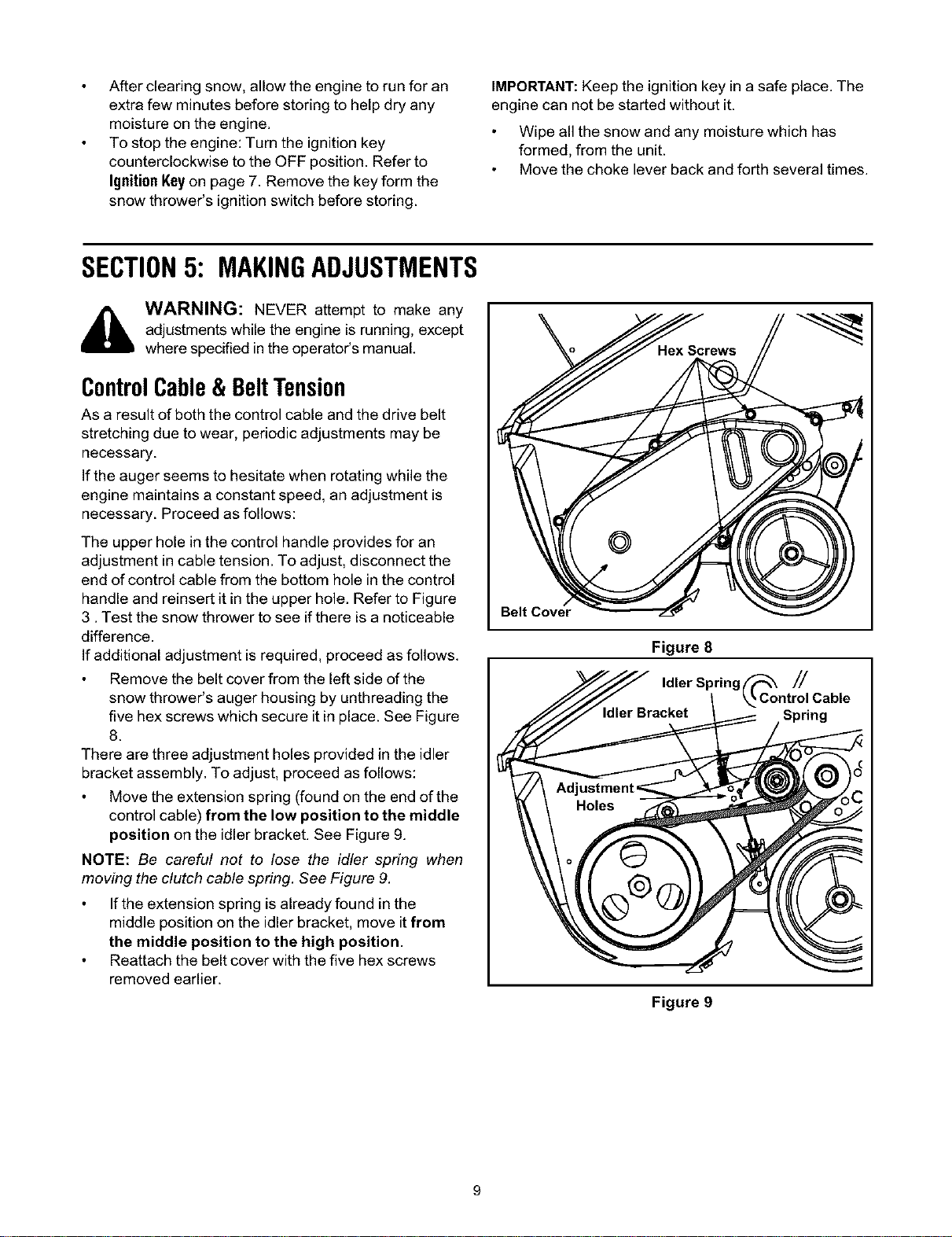
Remove the belt cover from the left side of the
snow thrower's auger housing by unthreading the
five hex screws which secure it in place. See Figure
8.
There are three adjustment holes provided in the idler
bracket assembly. To adjust, proceed as follows:
Move the extension spring (found on the end of the
control cable) from the low position to the middle
position on the idler bracket. See Figure 9.
NOTE: Be careful not to lose the idler spring when
moving the clutch cable spring. See Figure 9.
If the extension spring is already found in the
middle position on the idler bracket, move it from
the middle position to the high position.
Reattach the belt cover with the five hex screws
removed earlier.
Belt Cover
Figure 8
Idler Spring //
Spring
Figure 9
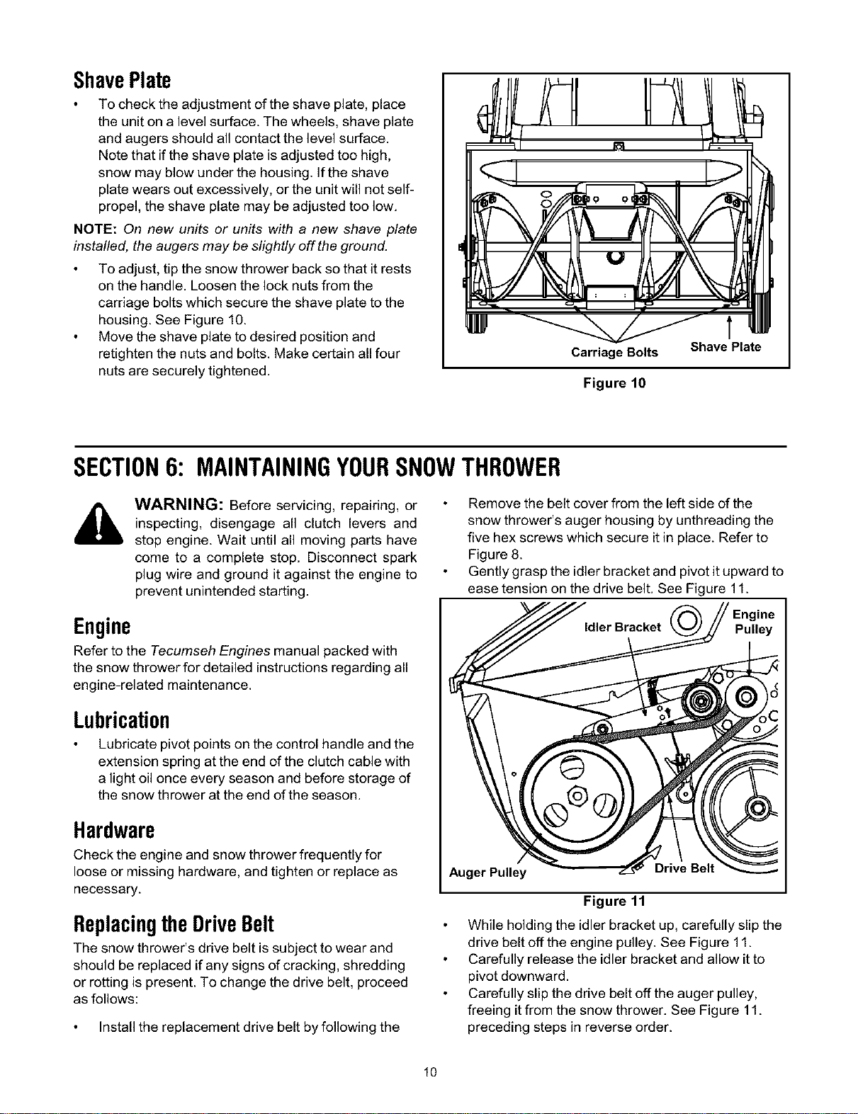
ShavePlate
To check the adjustment of the shave plate, place
the unit on a level surface. The wheels, shave plate
and augers should all contact the level surface.
Note that if the shave plate is adjusted too high,
snow may blow under the housing. If the shave
plate wears out excessively, or the unit will not self-
propel, the shave plate may be adjusted too low.
NOTE: On new units or units with a new shave plate
installed, the augers may be slightly off the ground.
To adjust, tip the snow thrower back so that it rests
on the handle. Loosen the lock nuts from the
carriage bolts which secure the shave plate to the
housing. See Figure 10.
Move the shave plate to desired position and
retighten the nuts and bolts. Make certain all four
nuts are securely tightened.
Carriage Bolts Shave Plate
Figure 10
SECTION6: MAINTAININGYOURSNOWTHROWER
WARNING: Before servicing, repairing, or
inspecting, disengage all clutch levers and
stop engine. Wait until all moving parts have
come to a complete stop. Disconnect spark
plug wire and ground it against the engine to
prevent unintended starting.
Engine
Refer to the Tecumseh Engines manual packed with
the snow thrower for detailed instructions regarding all
engine-related maintenance.
Lubrication
Lubricate pivot points on the control handle and the
extension spring at the end of the clutch cable with
a light oil once every season and before storage of
the snow thrower at the end of the season.
Hardware
Check the engine and snow thrower frequently for
loose or missing hardware, and tighten or replace as
necessary.
Replacingthe DriveBelt
The snow thrower's drive belt is subject to wear and
should be replaced if any signs of cracking, shredding
or rotting is present. To change the drive belt, proceed
as follows:
Install the replacement drive belt by following the
Remove the belt cover from the left side of the
snow thrower's auger housing by unthreading the
five hex screws which secure it in place. Refer to
Figure 8.
Gently grasp the idler bracket and pivot it upward to
ease tension on the drive belt. See Figure 11.
/ Engine
Pulley
Auger Pulley
Drive Belt
Figure 11
While holding the idler bracket up, carefully slip the
drive belt off the engine pulley. See Figure 11.
Carefully release the idler bracket and allow it to
pivot downward.
Carefully slip the drive belt off the auger pulley,
freeing it from the snow thrower. See Figure 11.
preceding steps in reverse order.
10
Reattach the belt cover with the five hex screws
removed earlier.
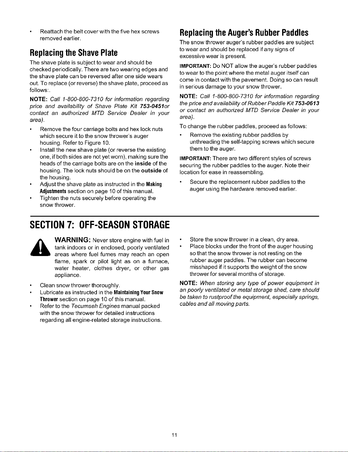
ReplacingtheShavePlate
The shave plate is subject to wear and should be
checked periodically. There are two wearing edges and
the shave plate can be reversed after one side wears
out. To replace (or reverse) the shave plate, proceed as
follows:.
NOTE: Call 1-800-800-7310 for information regarding
price and availability of Shave Plate Kit 753-0451or
contact an authorized MTD Service Dealer in your
area).
Remove the four carriage bolts and hex lock nuts
which secure it to the snow thrower's auger
housing. Refer to Figure 10.
Install the new shave plate (or reverse the existing
one, if both sides are not yet worn), making sure the
heads of the carriage bolts are on the inside of the
housing. The lock nuts should be on the outside of
the housing.
Adjust the shave plate as instructed in the Making
Adjustmentssection on page 10 of this manual.
Tighten the nuts securely before operating the
snow thrower.
ReplacingtheAuger'sRubberPaddles
The snow thrower auger's rubber paddles are subject
to wear and should be replaced if any signs of
excessive wear is present.
IMPORTANT: Do NOT allow the auger's rubber paddles
to wear to the point where the metal auger itself can
come in contact with the pavement. Doing so can result
in serious damage to your snow thrower.
NOTE: Call 1-800-800-7310 for information regarding
the price and availability of Rubber Paddle Kit 753-0613
or contact an authorized MTD Service Dealer in your
area).
To change the rubber paddles, proceed as follows:
Remove the existing rubber paddles by
unthreading the self-tapping screws which secure
them to the auger.
IMPORTANT:There are two different styles of screws
securing the rubber paddles to the auger. Note their
location for ease in reassembling.
Secure the replacement rubber paddles to the
auger using the hardware removed earlier.
SECTION7: OFF-SEASONSTORAGE
WARNING: Never store engine with fuel in
tank indoors or in enclosed, poorly ventilated
areas where fuel fumes may reach an open
flame, spark or pilot light as on a furnace,
water heater, clothes dryer, or other gas
appliance.
Clean snow thrower thoroughly.
Lubricate as instructed in the MaintainingYourSnow
Throwersection on page 10 of this manual.
Refer to the Tecumseh Engines manual packed
with the snow thrower for detailed instructions
regarding all engine-related storage instructions.
Store the snow thrower in a clean, dry area.
Place blocks under the front of the auger housing
so that the snow thrower is not resting on the
rubber auger paddles. The rubber can become
misshaped if it supports the weight of the snow
thrower for several months of storage.
NOTE: When storing any type of power equipment in
an poorly ventilated or metal storage shed, care should
be taken to rustproof the equipment, especially springs,
cables and all moving parts.
11
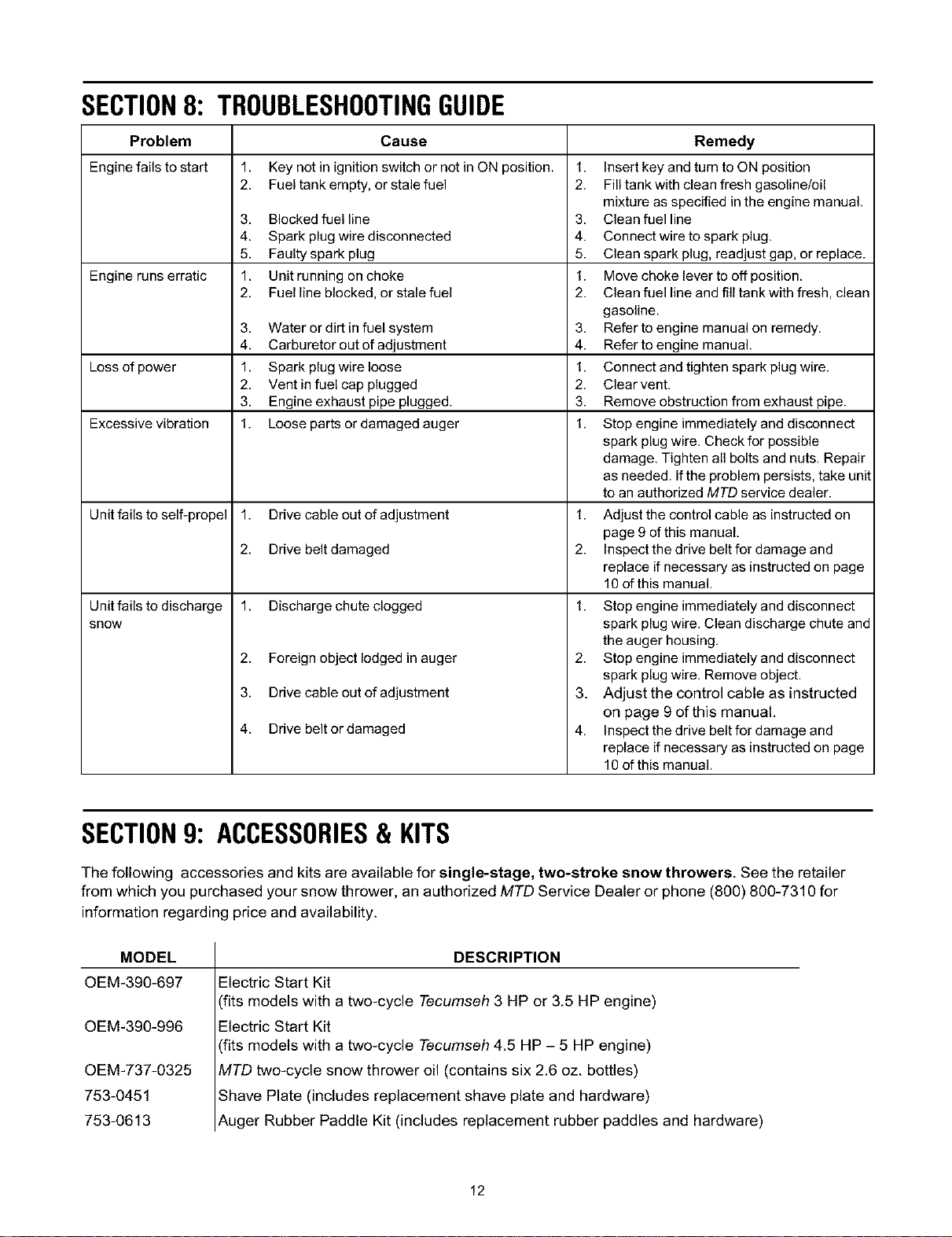
SECTION8: TROUBLESHOOTINGGUIDE
Problem Cause
Engine fails to start 1. Key not in ignition switch or not in ON position. 1.
2. Fuel tank empty, or stale fuel 2.
3. Blocked fuel line 3,
4. Spark plug wire disconnected 4.
5. Faulty spark plug 5.
Engine runs erratic 1. Unit running on choke 1.
2. Fuel line blocked, or stale fuel 2.
3.
4.
Loss of power 1.
2.
3.
Excessive vibration 1.
Unit fails to self-propel 1.
2.
Unit fails to discharge 1.
snow
2.
3.
4.
Water or dirt in fuel system 3.
Carburetor out of adjustment 4.
Spark plug wire loose 1.
Vent in fuel cap plugged 2.
Engine exhaust pipe plugged. 3.
Loose parts or damaged auger 1.
Drive cable out of adjustment 1.
Drive belt damaged 2.
Discharge chute clogged 1.
Foreign object lodged in auger
Drive cable out of adjustment
Drive belt or damaged
2.
3.
4.
Remedy
Insert key and turn to ON position
Fill tank with clean fresh gasoline/oil
mixture as specified in the engine manual.
Clean fuel line
Connect wire to spark plug.
Clean spark plug, readjust gap, or replace.
Move choke lever to off position.
Clean fuel line and fill tank with fresh, clean
gasoline.
Refer to engine manual on remedy.
Refer to engine manual.
Connect and tighten spark plug wire.
Clear vent.
Remove obstruction from exhaust pipe.
Stop engine immediately and disconnect
spark plug wire. Check for possible
damage. Tighten all bolts and nuts. Repair
as needed. Ifthe problem persists, take unit
to an authorized MTD service dealer.
Adjust the control cable as instructed on
page 9 of this manual.
Inspect the drive belt for damage and
replace if necessary as instructed on page
10 of this manual.
Stop engine immediately and disconnect
spark plug wire. Clean discharge chute and
the auger housing.
Stop engine immediately and disconnect
spark plug wire. Remove object.
Adjust the control cable as instructed
on page 9 of this manual.
Inspect the drive belt for damage and
replace if necessary as instructed on page
10 of this manual.
SECTION9: ACCESSORIES& KITS
The following accessories and kits are available for single-stage, two-stroke snow throwers. See the retailer
from which you purchased your snow thrower, an authorized MTD Service Dealer or phone (800) 800-7310 for
information regarding price and availability.
MODEL
OEM-390-697
OEM-390-996
OEM-737-0325
753-0451
753-0613
DESCRIPTION
Electric Start Kit
fits models with a two-cycle Tecumseh 3 HP or 3.5 HP engine)
Electric Start Kit
fits models with a two-cycle Tecumseh 4.5 HP - 5 HP engine)
VITDtwo-cycle snow thrower oil (contains six 2.6 oz. bottles)
Shave Plate (includes replacement shave plate and hardware)
Auger Rubber Paddle Kit (includes replacement rubber paddles and hardware)
12

13
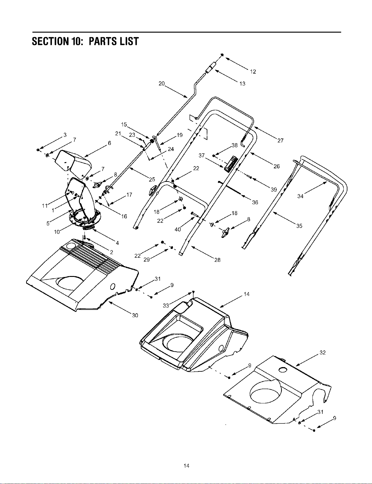
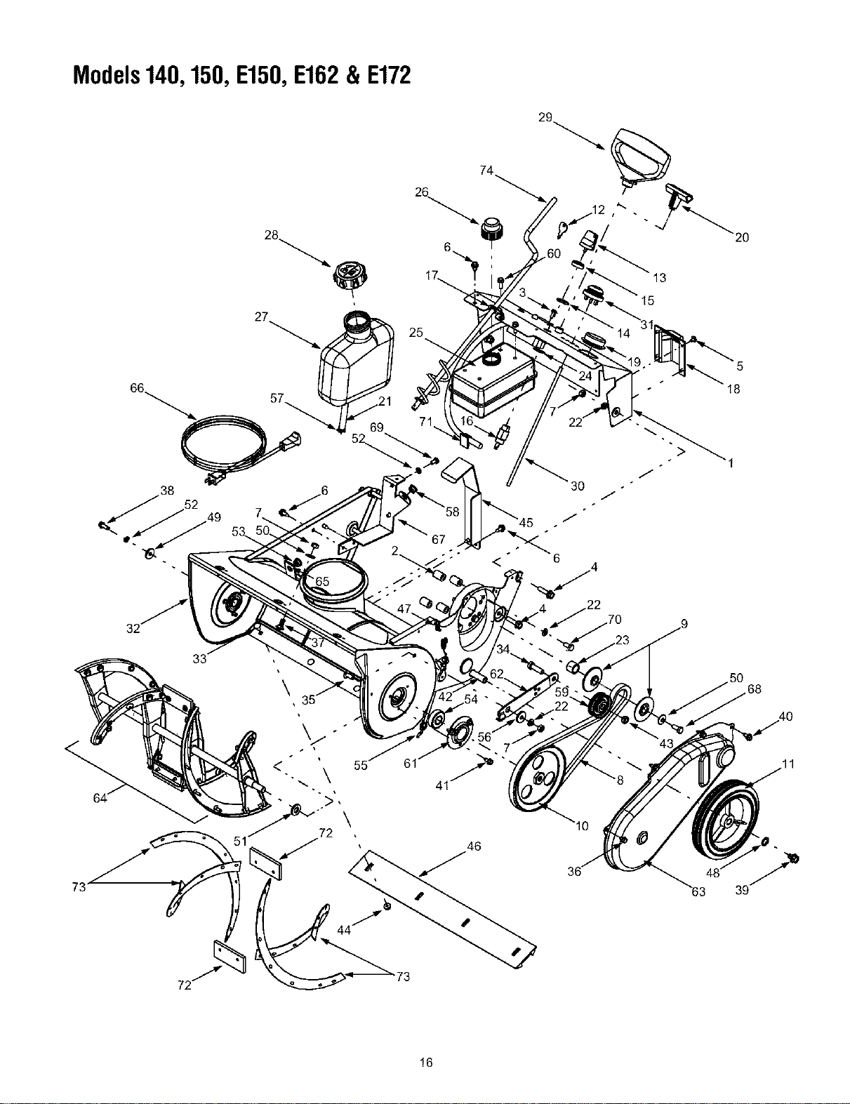
SECTION10: PARTSLIST
2O
12
13
21
J
37
22
0
3O
14
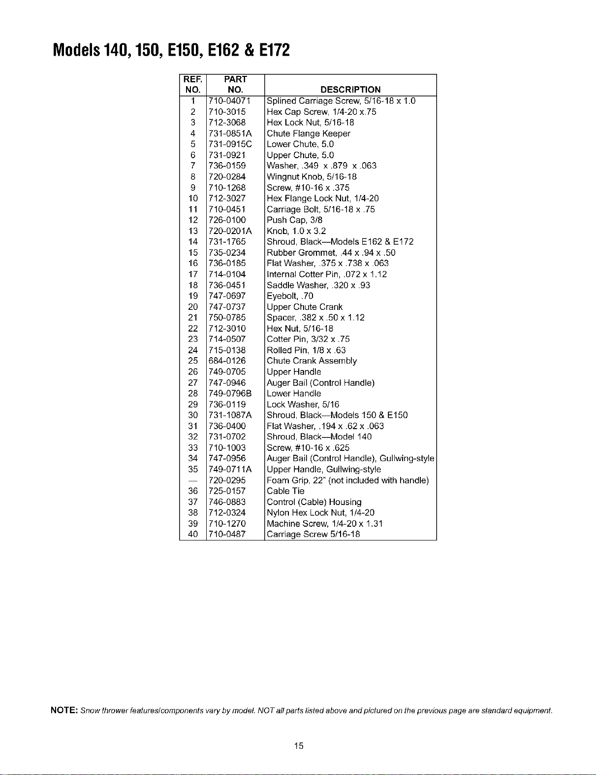
Models140,150,E150,E162& E172
REF.
NO,
1
2
3
4
5
6
7
8
9
10
11
12
13
14
15
16
17
18
19
2O
21
22
23
24
25
26
27
28
29
3O
31
32
33
34
35
36
37
38
39
4O
PART
NO.
710-04071
710-3015
712-3068
731-0851A
731-0915C
731-0921
736-0159
720-0284
710-1268
712-3027
710-0451
726-0100
720-0201A
731-1765
735-0234
736-0185
714-0104
736-0451
747-0697
747-0737
750-0785
712-3010
714-0507
715-0138
684-0126
749-0705
747-0946
749-0796B
736-0119
731-1087A
736-0400
731-0702
710-1003
747-0956
749-0711A
720-0295
725-0157
746-0883
712-0324
710-1270
710-0487
DESCRIPTION
Splined Carriage Screw, 5/16-18 x 1.0
Hex Cap Screw, 1/4-20 x.75
Hex Lock Nut, 5/16-18
Chute Flange Keeper
Lower Chute, 5.0
Upper Chute, 5.0
Washer, .349 x .879 x .063
Wingnut Knob, 5/16-18
Screw, #10-16 x ,375
Hex Flange Lock Nut, 1/4-20
Carriage Bolt, 5/16-18 x .75
Push Cap, 3/8
Knob, 1.0 x 3,2
Shroud, Black--Models E162 & E172
Rubber Grommet, .44 x .94 x .50
Flat Washer, .375 x ,738 x .063
Internal Cotter Pin, .072 x 1.12
Saddle Washer, .320 x .93
Eyebolt, .70
Upper Chute Crank
Spacer, .382 x .50 x 1.12
Hex Nut, 5/16-18
Cotter Pin, 3/32 x .75
Rolled Pin, 1/8 x .63
Chute Crank Assembly
Upper Handle
Auger Bail (Control Handle)
Lower Handle
Lock Washer, 5/16
Shroud, Black--Models 150 & E150
Flat Washer, ,194 x .62 x .063
Shroud, Black--Model 140
Screw, #10-16 x .625
Auger Bail (Control Handle), Gullwing-style
Upper Handle, Gullwing-style
Foam Grip, 22" (not included with handle)
Cable Tie
Control (Cable) Housing
Nylon Hex Lock Nut, 1/4-20
Machine Screw, 1/4-20 x 1.31
Carriage Screw 5/16-18
NOTE: Snow thrower features/components vary by model. NOT aft parts listed above and pictured on the prevtous page are standard equipment,
15
Models140,150,E150,E162& E172
\
29
74
2
2O
17_ 13
25
18
67
o .
<" 6
>
<" "_ \ 55
46
I0
16
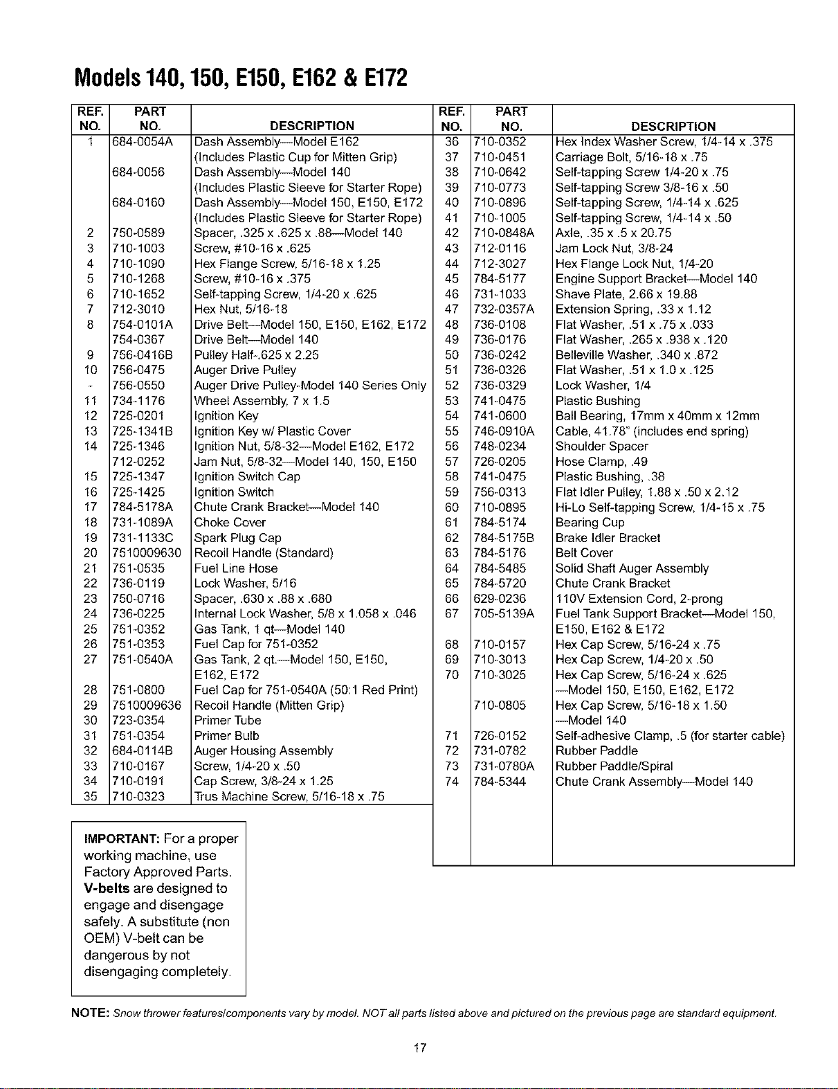
Models140,150,E150,E162& E172
REF. PART
NO, NO.
1 684-0054A
684-0056
684-0160
2 750-0589
3 710-1003
4 710-1090
5 710-1268
6 710-1652
7 712-3010
8 754-0101A
754-0367
9 756-0416B
10 756-0475
756-0550
11 734-1176
12 725-0201
13 725-1341B
14 725-1346
712-0252
15 725-1347
16 725-1425
17 784-5178A
18 731-1089A
19 731-1133C
20 7510009630
21 751-0535
22 736-0119
23 750-0716
24 736-0225
25 751-0352
26 751-0353
27 751-0540A
28 751-0800
29 7510009636
30 723-0354
31 751-0354
32 684-0114B
33 710-0167
34 710-0191
35 710-0323
REF. PART
DESCRIPTION NO. NO.
Dash Assembly--Model E162 36 710-0352
(Includes Plastic Cup for Mitten Grip) 37 710-0451
Dash Assembly--Model 140 38 710-0642
(Includes Plastic Sleeve for Starter Rope) 39 710-0773
Dash Assembly--Model 150, E150, E172 40 710-0896
(includes Plastic Sleeve for Starter Rope) 41 710-1005
Spacer, .325 x .625 x .88--Model 140 42 710-0848A
Screw, #10-16 x .625 43 712-0116
Hex Flange Screw, 5/16-18 x 1.25 44 712-3027
Screw, #10-16 x .375 45 784-5177
Self4apping Screw, 1/4-20 x .625 46 731-1033
Hex Nut, 5/16-18 47 732-0357A
Drive Belt_Mode1150, E150, E162, E172 48 736-0108
Drive Belt_Mode1140 49 736-0176
Pulley Half-.625 x 2.25 50 736-0242
Auger Drive Pulley 51 736-0326
Auger Drive Pulley-Model 140 Series Only 52 736-0329
Wheel Assembly, 7 x 1.5 53 741-0475
Ignition Key 54 741-0600
Ignition Key w/Plastic Cover 55 746-0910A
Ignition Nut, 5/8-32--Model E162, E172 56 748-0234
Jam Nut, 5/8-32--Model 140, 150, E150 57 726-0205
Ignition Switch Cap 58 741-0475
Ignition Switch 59 756-0313
Chute Crank Bracket Model 140 60 710-0895
DESCRIPTION
Hex Index Washer Screw, 1/4-14 x .375
Carriage Bolt, 5/16-18 x .75
Self4apping Screw 1/4-20 x .75
Self4apping Screw 3/8-16 x .50
Self4apping Screw, 1/444 x .625
Self4apping Screw, 1/4-14 x .50
Axle, .35 x .5 x 20.75
Jam Lock Nut, 3/8-24
Hex Flange Lock Nut, 1/4-20
Engine Support Bracket_Mode1140
Shave Plate, 2.66 x 19.88
Extension Spring, .33 x 1.12
Flat Washer, .51 x .75 x .033
Flat Washer, .265 x .938 x .120
Belleville Washer, .340 x .872
Hat Washer, .51 x 1.0 x .125
Lock Washer, 1/4
Plastic Bushing
Ball Bearing, 17mm x 40mm x 12mm
Cable, 41.78" (includes end spring)
Shoulder Spacer
Hose Clamp, .49
Plastic Bushing, .38
Flat Idler Pulley, 1,88 x ,50 x 2.12
Hi-Lo Self-tapping Screw, 1/4-15 x .75
Choke Cover 61 784-5174
Spark Plug Cap 62 784-5175B
Recoil Handle (Standard) 63 784-5176
Fuel Line Hose 64 784-5485
Lock Washer, 5/16 65 784-5720
Spacer, .630 x .88 x .680 66 629-0236
Internal Lock Washer, 518x 1.058 x .046 67 705-5139A
Gas Tank, 1 qt_Mode1140
Fuel Cap for 751-0352 68 710-0157
Gas Tank, 2 qt.--Mode1150, E150, 69 710-3013
E162, E172 70 710-3025
Fuel Cap for 751-0540A (50:1 Red Print)
Bearing Cup
Brake Idler Bracket
Belt Cover
Solid Shaft Auger Assembly
Chute Crank Bracket
110V Extension Cord, 2-prong
Fuel Tank Support Bracket_Mode1150,
E150, E162 & E172
Hex Cap Screw, 5116-24 x .75
Hex Cap Screw, 114-20 x .50
Hex Cap Screw, 5116-24 x .625
--Model 150, E150, E162, E172
Recoil Handle (Mitten Grip) 710-0805
Primer Tube
Primer Bulb 71 726-0152
Auger Housing Assembly 72 731-0782
Screw, 1/4-20 x .50 73 731-0780A
Cap Screw, 3/8-24 x 1.25 74 784-5344
Trus Machine Screw, 5116-18 x .75
Hex Cap Screw, 5116-18 x 1.50
--Model 140
Self-adhesive Clamp, .5 (for starter cable)
Rubber Paddle
Rubber Paddle/Spiral
Chute Crank Assembly--Model 140
]
IMPORTANT: Fora proper /
working machine, use
/
Factory Approved Parts.
V-belts are designed to
engage and disengage
safely. A substitute (non
OEM) V-belt can be
dangerous by not
disengaging completely.
NOTE: Snow thrower features/components vary by model. NOT aft parts listed above and pictured on the previous page are standard equipment,
17

18

MANUFACTURER'S LIMITED WARRANTY FOR:
The limited warranty set forth below is given by MTD LLC with
respect to new merchandise purchased and used in the
United States, its possessions and territories.
MTD LLC warrants this product against defects for a period of
two (2) years commencing on the date of original purchase
and will, at its option, repair or replace, free of charge, any
part found to be defective in materials or workmanship, This
limited warranty shall only apply if this product has been
operated and maintained in accordance with the Operator's
Manual furnished with the product, and has not been subject
to misuse, abuse, commercial use, neglect, accident,
improper maintenance, alteration, vandalism, theft, fire,
water, or damage because of other peril or natural disaster.
Damage resulting from the installation or use of any
accessory or attachment not approved by MTD LLC for use
with the product(s) covered by this manual will void your
warranty as to any resulting damage.
Normal wear parts or components thereof are subject to
separate terms as follows: All normal wear parts or
component failures will be covered on the product for a period
of 90 days regardless of cause. After 90 days, but within the
two year period, normal wear part failures will be covered
ONLY IF caused by defects in materials or workmanship of
OTHER component parts. Normal wear parts and
components include, but are not limited to: batteries, belts,
blades, blade adapters, grass bags, rider deck wheels, seats,
snow thrower skid shoes, shave plates, auger spiral rubber,
and tires.
HOW TO OBTAIN SERVICE: Warranty service is available,
WITH PROOF OF PURCHASE, through your local authorized
service dealer. To locate the dealer in your area, check your
Yellow Pages, or contact MTD LLC at P.O. Box 361131,
Cleveland, Ohio 44136-0019, or call 1-800-800-7310 or 1-
330-220-4683 or log on to our Web site at
www.mtdproducts.com.
This limited warranty does not provide coverage in the
following cases:
a. The engine or component parts thereof. These items
carry a separate manufacturer's warranty, Refer to
applicable manufacturer's warranty for terms and
conditions.
b. Log splitter pumps, valves, and cylinders have a sepa
rate one year warranty.
c. Routine maintenance items such as lubricants, filters,
blade sharpening, tune-ups, brake adjustments, clutch
adjustments, deck adjustments, and normal
deterioration of the exterior finish due to use or
d. MTD LLC does not extend any warranty for products
sold or exported outside of the United States, its
possesions and territories, except those sold through
MTD LLC's authorized channels of export distribution.
e. Parts that are not genuine MTD parts are not covered
by this warranty.
f. Service completed by someone other than an
authorized service dealer is not covered by this
warranty.
g. Transportation charges and service calls are not
covered.
No implied warranty, including any implied warranty of
merchantability of fitness for a particular purpose,
applies after the applicable period of express written
warranty above as to the parts as identified. No other
express warranty, whether written or oral, except as
mentioned above, given by any person or entity,
including a dealer or retailer, with respect to any product,
shall bind MTD LLC. During the period of the warranty,
the exclusive remedy is repair or replacement of the
product as set forth above.
The provisions as set forth in this warranty provide the
sole and exclusive remedy arising from the sale. MTD
LLC shall not be liable for incidental or consequential
loss or damage including, without limitation, expenses
incurred for substitute or replacement lawn care services
or for rental expenses to temporarily replace a warranted
product.
Some states do not allow the exclusion or limitation of
incidental or consequential damages, or limitations on how
long an implied warranty lasts, so the above exclusions or
limitations may not apply to you.
In no event shall recovery of any kind be greater than the
amount of the purchase price of the product sold. Alteration
of safety features of the product shall void this warranty.
You assume the risk and liability for loss, damage, or injury to
you and your property and/or to others and their property
arising out of the misuse or inability to use the product.
This limited warranty shall not extend to anyone other than the
original purchaser or to the person for whom it was purchased
as a gift.
HOW STATE LAW RELATES TO THIS WARRANTY: This
limited warranty gives you specific legal rights, and you may
also have other rights which vary from state to state.
exposure.
MTDLLC, P.O.BOX361131CLEVELAND,OHIO44136-0019; Phone:1-800-800-7310,1-330-220-4683