Loading ...
Loading ...
Loading ...
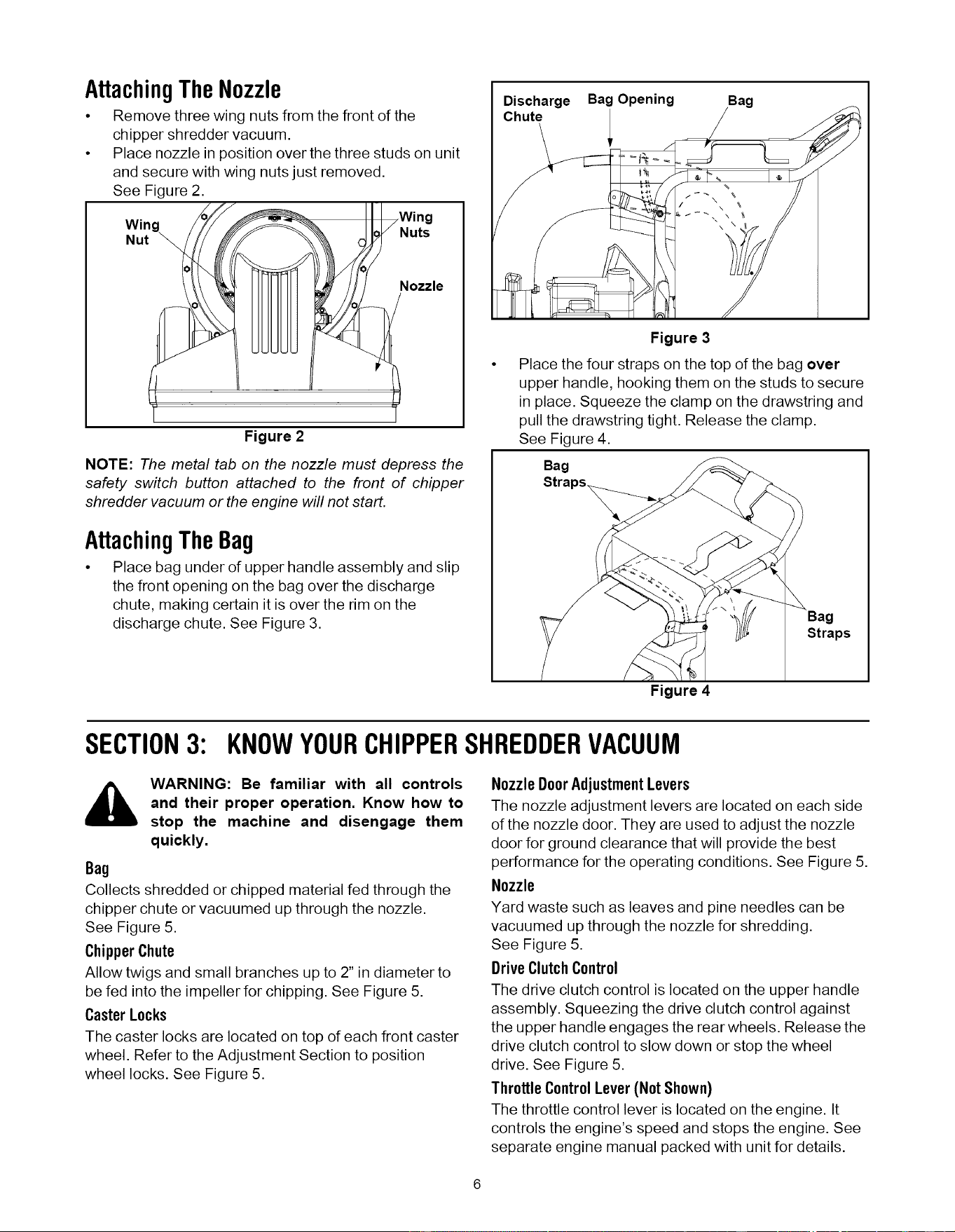
AttachingTheNozzle
• Remove three wing nuts from the front of the
chipper shredder vacuum.
• Place nozzle in position over the three studs on unit
and secure with wing nuts just removed.
See Figure 2.
Figure 2
II I Wing
Nuts
ozzle
NOTE: The metal tab on the nozzle must depress the
safety switch button attached to the front of chipper
shredder vacuum or the engine will not start.
AttachingTheBag
• Place bag under of upper handle assembly and slip
the front opening on the bag over the discharge
chute, making certain it is over the rim on the
discharge chute. See Figure 3.
Discharge Bag Opening
Chute
Bag
Figure 3
Place the four straps on the top of the bag over
upper handle, hooking them on the studs to secure
in place. Squeeze the clamp on the drawstring and
pull the drawstring tight. Release the clamp.
See Figure 4.
Bag
Bag
Straps
Figure 4
SECTION3: KNOWYOURCHIPPERSHREDDERVACUUM
WARNING: Be familiar with all controls
and their proper operation. Know how to
stop the machine and disengage them
quickly.
Bag
Collects shredded or chipped material fed through the
chipper chute or vacuumed up through the nozzle.
See Figure 5.
Chipper Chute
Allow twigs and small branches up to 2" in diameter to
be fed into the impeller for chipping. See Figure 5.
CasterLocks
The caster locks are located on top of each front caster
wheel. Refer to the Adjustment Section to position
wheel locks. See Figure 5.
Nozzle Door AdjustmentLevers
The nozzle adjustment levers are located on each side
of the nozzle door. They are used to adjust the nozzle
door for ground clearance that will provide the best
performance for the operating conditions. See Figure 5.
Nozzle
Yard waste such as leaves and pine needles can be
vacuumed up through the nozzle for shredding.
See Figure 5.
DriveClutch Control
The drive clutch control is located on the upper handle
assembly. Squeezing the drive clutch control against
the upper handle engages the rear wheels. Release the
drive clutch control to slow down or stop the wheel
drive. See Figure 5.
ThrottleControlLever(Not Shown)
The throttle control lever is located on the engine. It
controls the engine's speed and stops the engine. See
separate engine manual packed with unit for details.
Loading ...
Loading ...
Loading ...