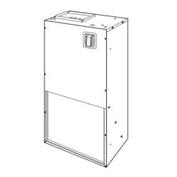
INSTALLATION
INSTRUCTIONS
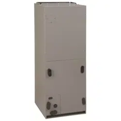
Apartment Air
Handler
Use ONLY factory listed electric heaters.
FWM1805A1
FWM1807A1
FWM1811A1
Models
FWM1800A1*
FWM2400A1*
FWM3000A1 *
FWM2405A1
FWM2407A1
FWM2411A1
FWM3005A1
FWM3007A1
FWM3011A1
*Requires
AMWK001CK1
Cooling Only Control Kit
General Information / Installation ............ 2
Installations ............................... 3
Ductwork Connections ..................... 3
Condensate Drain .......................... 4
Orifice Sizing & Refrigerant Lines ............ 4
Field Installation of Controls ................ 5
Electrical Connections ...................... 5
Motor Speeds .............................. 6
Wiring Diagram ............................ 7
Replacement Parts ......................... 8
SafetyLabelingand SignalWords
Danger,Warning and Caution
The signal words DANGER, WARNING and CAUTION
are used to identify levels of hazard seriousness. The
signal word DANGER is only used on product labels to
signify an immediate hazard. The signal words WARN-
ING and CAUTION will be used on product labels and
throughout this manual and other manuals that may ap-
ply to the product.
DANGER - immediate hazards which WILL result inse-
vere personal injury or death.
WARNING - Hazards or unsafe practices which
COULD result in severe personal injury or death.
CAUTION - Hazards or unsafe practices which COULD
result in minor personal injury or product or property
damage.
Signal Words in Manuals
The signal word WARNING is used throughout this
manual in the following manner:
The signal word CAUTION is used throughout this
manual in the following manner:
CAUTION
Product Labeling
Signal words are used in combination with colors and/or
pictures on product labels.
Printed in U.S.A. 664 01 3001 00
Nov 2000
I Installation Instructions Blower Cabinet I
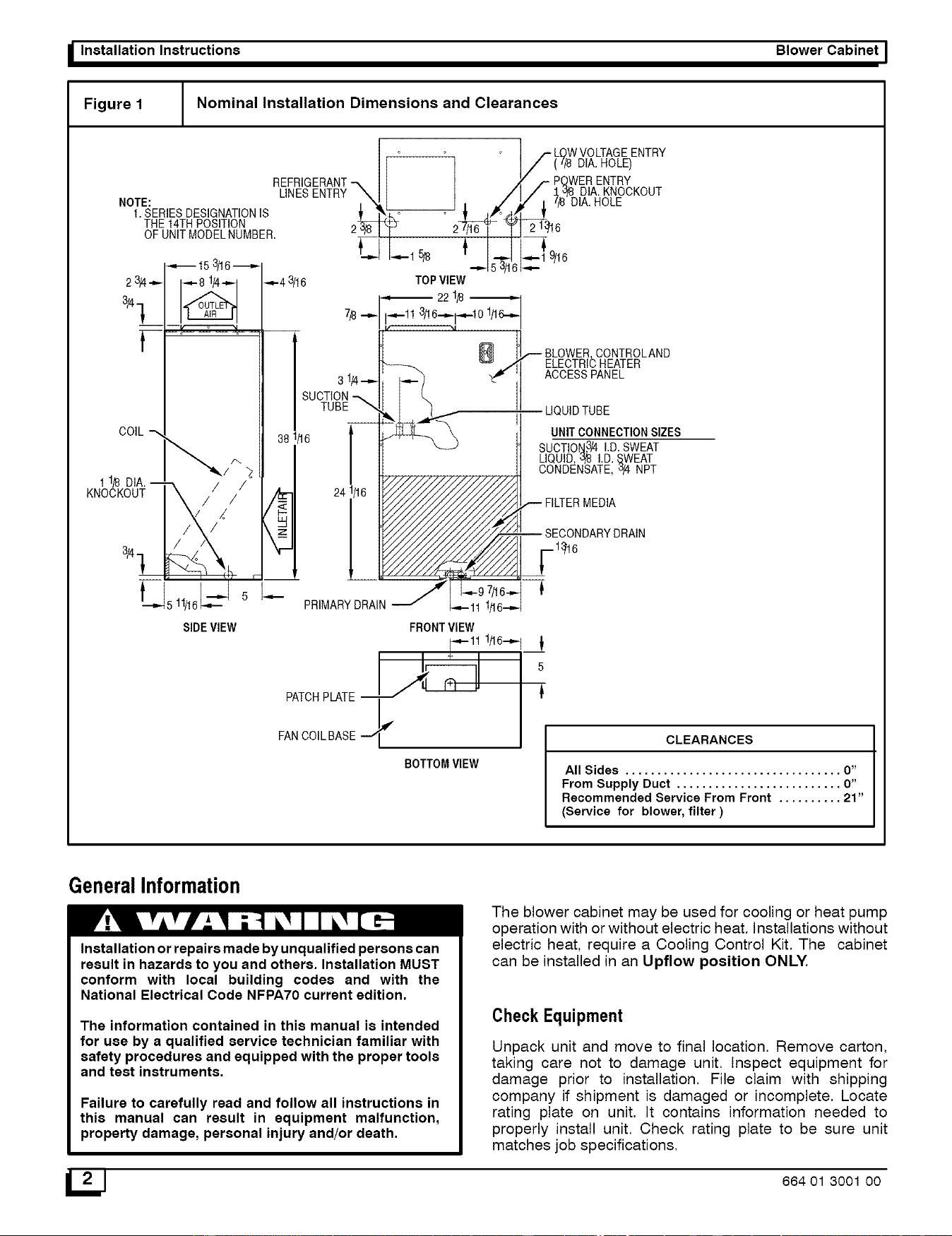
Figure 1 Nominal Installation Dimensions and Clearances
REFRIGERANT
LINESENTRY
NOTE:
1. SERIESDESIGNATIONIS
THE 14THPOSITION
OF UNITMODELNUMBER.
38 1/'16 I
241/16
_/_ LOWVOLTAGEENTRY
(`'/8 DIA. ROLE)
POWERENTRY
:L'J/8DIA. KNOCKOUT
"/8 DIA.HOLE
2 1_16
•_,-_ 9/16
i-<--
@
BLOWER,CONTROLAND
ELECTRICHEATER
ACCESSPANEL
LIQUIDTUBE
UNITCONNECTIONSIZES
SUCTION3/4I.D. SWEAT
LIQUID,3_ I.D._WEAT
CONDENSATE,_/4 NPT
,-- FILTERMEDIA
-- SECONDARYDRAIN
1_16
I-- PRIMARY DRAIN J -,-97/16--
-4-11 1/16-=-
FRONTVIEW
_-11 1/16-----1_[
PATCHPLATE ._L_ 5
FANCOILBASE #
BOTTOMVIEW
CLEARANCES
All Sides .................................. 0"
From Supply Duct .......................... O"
Recommended Service From Front .......... 21"
(Service for blower, filter)
GeneralInformation
Installation or repairs made by unqualified persons can
result in hazards to you and others. Installation MUST
conform with local building codes and with the
National Electrical Code NFPA70 current edition.
The information contained in this manual is intended
for use by a qualified service technician familiar with
safety procedures and equipped with the proper tools
and test instruments.
Failure to carefully read and follow all instructions in
this manual can result in equipment malfunction,
property damage, personal injury and/or death.
The blower cabinet may be used for cooling or heat pump
operation with or without electric heat. Installations without
electric heat, require a Cooling Control Kit. The cabinet
can be installed in an Upflow position ONLY.
Check Equipment
Unpack unit and move to final location. Remove carton,
taking care not to damage unit. Inspect equipment for
damage prior to installation. File claim with shipping
company if shipment is damaged or incomplete. Locate
rating plate on unit. It contains information needed to
properly install unit. Check rating plate to be sure unit
matches job specifications.
_J 664 01 3001 O0
I Blower Cabinet
Location
Select the best position which suits the installation site
conditions. The location should provide adequate
structural support, space in the front of the unit for service
access, clearance for return air and supply duct
connections, space for refrigerant piping connections and
condensate drain line connections.
See Clearances in Figure 1.
A front access panel is provided, which permits access to
blower assembly and electrical controls for removal and
servicing.
NOTE: Local codes may limit application of systems
without a ducted return to single story dwellings.
Installation
The unit is designed for free-air return as enclosed in a
closet with Iouvered door or for flush mounting in a wall. A
factory-authorized Iouvered grille kit is available for flush
mount application (AMWK001WG).
When unit is installed in a closet with a Iouvered door in
return-air path, the free area of Iouvered opening in the
door must be a minimum of 2.25 sq ft. Either align door
opening with unit inlet or provide a l O-in. clearance
between door and unit.
If unit is to be flush mounted in a wall, provide adequate
support underneath base of unit. To assure proper
condensate drainage, be sure unit is level.
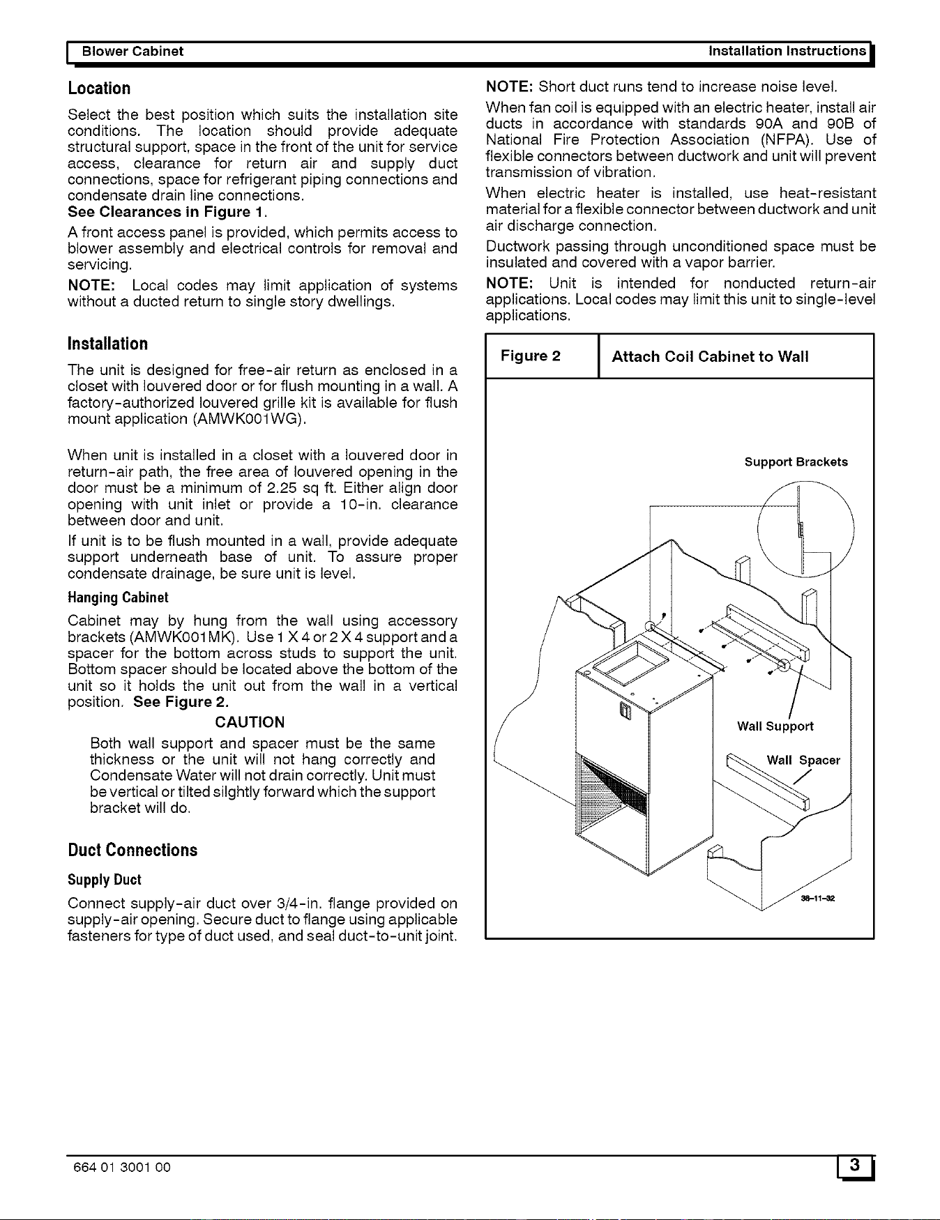
HangingCabinet
Cabinet may by hung from the wall using accessory
brackets (AMWK001MK). Use 1X 4 or 2 X 4 support and a
spacer for the bottom across studs to support the unit.
Bottom spacer should be located above the bottom of the
unit so it holds the unit out from the wall in a vertical
position, See Figure 2,
CAUTION
Both wall support and spacer must be the same
thickness or the unit will not hang correctly and
Condensate Water will not drain correctly. Unit must
be vertical or tilted slightly forward which the support
bracket will do.
Duct Connections
SupplyDuct
Connect supply-air duct over 3/4-in. flange provided on
supply-air opening. Secure duct to flange using applicable
fasteners for type of duct used, and seal duct-to-unit joint.
Installation Instructions
NOTE: Short duct runs tend to increase noise level.
When fan coil is equipped with an electric heater, install air
ducts in accordance with standards 90A and 90B of
National Fire Protection Association (NFPA). Use of
flexible connectors between ductwork and unit will prevent
transmission of vibration.
When electric heater is installed, use heat-resistant
material for a flexible connector between ductwork and unit
air discharge connection.
Ductwork passing through unconditioned space must be
insulated and covered with a vapor barrier.
NOTE: Unit is intended for nonducted return-air
applications. Local codes may limit this unit to single-level
applications.
Figure 2 Attach Coil Cabinet to Wall
Support Brackets
664 01 3001 00 3L_ J
_ Installation Instructions Blower Cabinet I
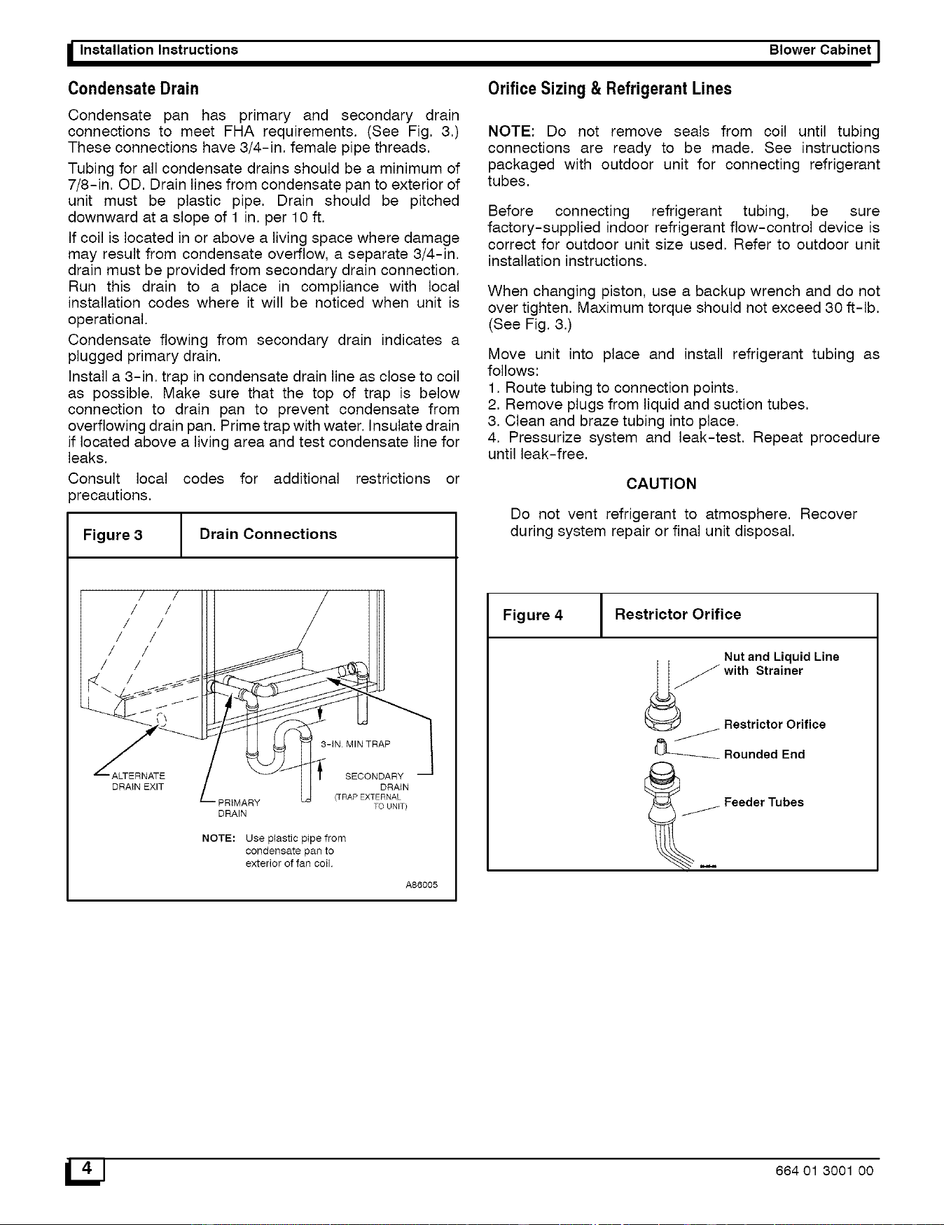
Condensate Drain
Condensate pan has primary and secondary drain
connections to meet FHA requirements. (See Fig. 3.)
These connections have 3/4-in. female pipe threads.
Tubing for all condensate drains should be a minimum of
7/8-in. OD. Drain lines from condensate pan to exterior of
unit must be plastic pipe. Drain should be pitched
downward at a slope of 1 in. per 10 ft.
If coil is located in or above a living space where damage
may result from condensate overflow, a separate 3/4-in.
drain must be provided from secondary drain connection.
Run this drain to a place in compliance with local
installation codes where it will be noticed when unit is
operational.
Condensate flowing from secondary drain indicates a
plugged primary drain.
Install a 3-in. trap in condensate drain line as close to coil
as possible. Make sure that the top of trap is below
connection to drain pan to prevent condensate from
overflowing drain pan. Prime trap with water. Insulate drain
if located above a living area and test condensate line for
leaks.
Consult local codes for additional restrictions or
)recautions.
Figure 3 Drain Connections
/
/
/
/
/
DRAIN EXIT
PRIMARY
DRAIN
SECONDARY
DRAIN
(TRAP EXTERNAL
TO UNIT)
NOTE: Use plastic pipe from
condensate pan to
exterior of fan coil.
A86005
Orifice Sizing & Refrigerant Lines
NOTE: Do not remove seals from coil until tubing
connections are ready to be made. See instructions
packaged with outdoor unit for connecting refrigerant
tubes.
Before connecting refrigerant tubing, be sure
factory-supplied indoor refrigerant flow-control device is
correct for outdoor unit size used. Refer to outdoor unit
installation instructions.
When changing piston, use a backup wrench and do not
over tighten. Maximum torque should not exceed 30 ft-lb.
(See Fig. 3.)
Move unit into place and install refrigerant tubing as
follows:
1. Route tubing to connection points.
2. Remove plugs from liquid and suction tubes.
3. Clean and braze tubing into place.
4. Pressurize system and leak-test. Repeat procedure
until leak-free.
CAUTION
Do not vent refrigerant to atmosphere. Recover
during system repair or final unit disposal.
Figure 4 Restrictor Orifice
Nut and Liquid Line
_-_ Rounded End
__ Feeder Tubes
_J 664 01 3001 00
I Blower Cabinet
FieldInstallation of Controls
Units shipped from factory without heaters require a
field-installed cooling control kit or heater. These kits are
completely assembled and factory-wired for easy
installation.
See Installation Instructions packaged with heaters for
installation procedures. These unit Installation Instructions
are to be used in conjunction with instructions packaged
with heater. When installing accessory heat, optional
cooling control kit is not required.
INSTALLCOOLINGCONTROLPACKAGE
1. Remove blower access panel (See Fig. 5.)
2. Install cooling control panel above blower motor on
blower side plate. Attach with provided screws. (See
Fig. 5.)
3. Route thermostat leads through small knockout in top
of unit. Use grommet provided with cooling control to
protect leads where they pass through casing.
4. Make low-voltage splice connections in low-voltage
control box.
5. Route blower motor power leads up through hole in
bottom of cooling control. Connect yellow common
wire to piggyback common terminal on transformer.
Connect black (HI) or red (LOW) speed tap wire to
control board relay common terminal. See wiring
label for proper speed tap selection.
6. Route unit power supply through knockout in top of
unit and connect to line side of disconnect. Connect
ground wire to ground lug. See wiring label to make
connections.
7. Remove disconnect pullout.
8. Replace access panel.
ELECTRICAL CONNECTIONS
Electrical shock hazard.
Before installing or servicing fan coil, always turn
off all power to unit. There may be more than 1 dis-
connect switch. Turn off accessory heater power
if applicable.
Field wires on side of disconnect found in fan coil
remain live, even when pull-out is removed. Ser-
vice and maintenance to incoming wiring can not
be performed until main disconnect switch (re-
mote to the unit) is turned off.
Failure to do so can result in property damage,
personal injury and/or death.
NOTE: Before proceeding with electrical connections,
make certain that voltage, frequency, and phase
correspond to that specified on rating plate. Also, check to
be sure that the service provided by utility is sufficient to
handle additional load imposed by this equipment. Refer to
unit wiring label for proper field high- and low-voltage
wiring. Make all electrical connections in accordance with
Installation Instructions
9, Insert disconnect pullout through hole in access
panel,
Figure 5 Cooling Control Kit
Ag8333
NOTE: Top panel not shown for ciarity
BLOWER
ACCESS UNIT
DOOR
A98335
NEC and any local codes or ordinances that might apply.
Unit must have a separate branch electrical circuit. The
Cooling Control Kit and the heater packages provide a
disconnect switch located within sight and readily
accessible to the unit.
NOTE: All control kits are shipped from factory wired for
230-v transformer operation. For 208-v operation, move
black primary lead from 230-v terminal to 208-v terminal.
See Fig. 6 and 7 for field low-voltage wiring. See Fig. 1 for
location of the electrical inlets. For maximum ampacity and
over-current protection, see unit rating plate.
1. Provide power supply for unit being installed in
accordance with unit wiring diagram and rating plate.
2,
3,
4,
Connect line-voltage leads to field lugs, Use copper
wire only.
Use UL listed conduit and conduit connector for
connecting line-voltage leads to unit and obtaining
proper ground. Grounding can also be accomplished
by using the ground lug provided in the control box.
Install rubber grommet packed with unit in hole for
low-voltage wires.
664 01 3001 O0 5L_
_ Installation Instructions Blower Cabinet I
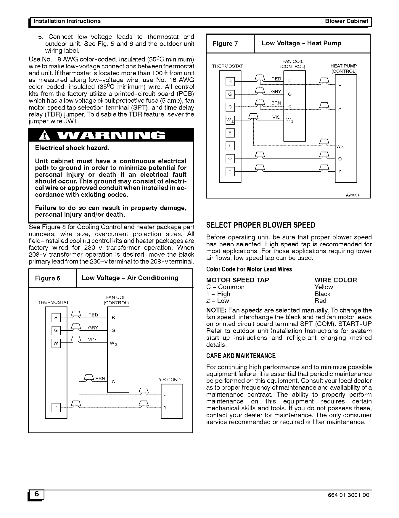
5. Connect low-voltage leads to thermostat and
outdoor unit. See Fig. 5 and 6 and the outdoor unit
wiring label.
Use No. 18 AWG color-coded, insulated (35°C minimum)
wire to make low-voltage connections between thermostat
and unit. If thermostat is located more than 100 ft from unit
as measured along low-voltage wire, use No. 16 AWG
color-coded, insulated (35°C minimum) wire. All control
kits from the factory utilize a printed-circuit board (PCB)
which has a low voltage circuit protective fuse (5 amp), fan
motor speed tap selection terminal (SPT), and time delay
relay (TDR) jumper. To disable the TDR feature, sever the
jumper wire JWl.
Electrical shock hazard.
Unit cabinet must have a continuous electrical
path to ground in order to minimize potential for
personal injury or death if an electrical fault
should occur. This ground may consist of electri-
cal wire or approved conduit when installed in ac-
cordance with existing codes.
Failure to do so can result in property damage,
personal injury and/or death.
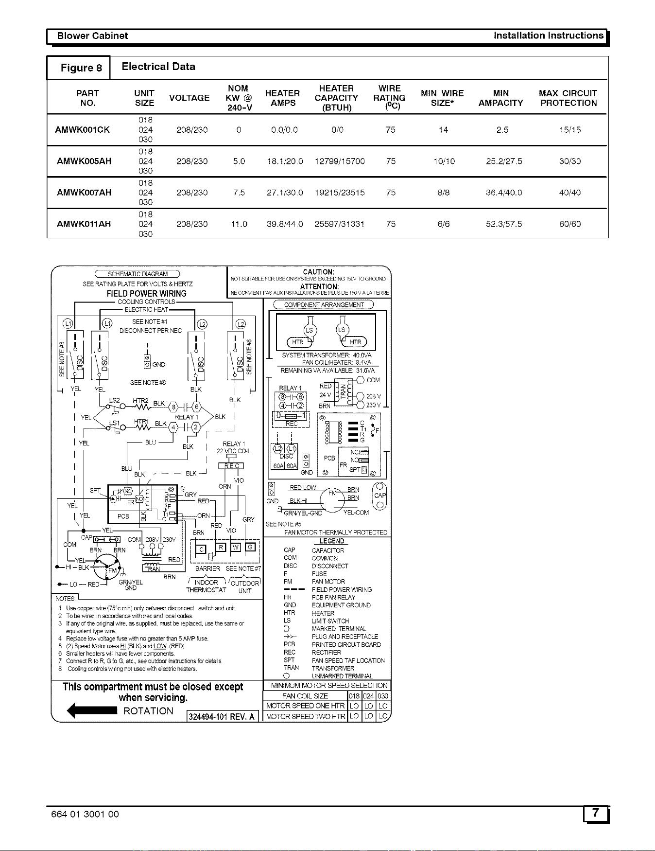
See Figure 8 for Cooling Control and heater package part
numbers, wire size, overcurrent protection sizes. All
field-installed cooling control kits and heater packages are
factory wired for 230-v transformer operation. When
208-v transformer operation is desired, move the black
primary lead from the 230-v terminal to the 208-v terminal.
Figure 6 Low Voltage - Air Conditioning
THERMOSTAT
FAN COIL
(CONTROL)
R
G
_ w2
AIR COND.
Figure 7 Low Voltage - Heat Pump
THERMOSTAT
[]
[]
FAN COIL
(CONTROL)
VlO W2
HEAT PUMP
(CONTROL)
4Q_ R
fi:3_c
W2
4:::%0
fi: _y
A98331
SELECT PROPER BLOWERSPEED
Before operating unit, be sure that proper blower speed
has been selected. High speed tap is recommended for
most applications. For those applications requiring lower
air flows, low speed tap can be used.
ColorCodeForMotorLeadWires
MOTOR SPEED TAP WIRE COLOR
C - Common Yellow
1 - High Black
2 - Low Red
NOTE: Fan speeds are selected manually. To change the
fan speed, interchange the black and red fan motor leads
on printed circuit board terminal SPT (COM). START-UP
Refer to outdoor unit Installation Instructions for system
start-up instructions and refrigerant charging method
details.
CAREAND MAINTENANCE
For continuing high performance and to minimize possible
equipment failure, it is essential that periodic maintenance
be performed on this equipment. Consult your local dealer
as to proper frequency of maintenance and availability of a
maintenance contract. The ability to properly perform
maintenance on this equipment requires certain
mechanical skills and tools. If you do not possess these,
contact your dealer for maintenance. The only consumer
service recommended or required is filter maintenance.
_J 664 01 3001 00
I Blower Cabinet Installation Instructions
Figure 8 J Electrical Data
NOM HEATER WIRE
PART UNIT HEATER MIN WIRE MIN MAX CIRCUIT
CAPACITY RATING
NO. SIZE VOLTAGE KW @ AMPS SIZE* AMPACITY PROTECTION
240-V (BTUH) (°C)
018
AMWK001CK 024 208/230 0 0.0/0.0 0/0 75 14 2.5 15/15
O3O
018
AMWK005AH 024 208/230 5.0 18.1/20.0 12799/15700 75 10/10 25,2/27.5 30/30
O3O
018
AMWK007AH 024 208/230 7.5 27.1/30.0 19215/23515 75 8/8 36.4/40.0 40/40
O3O
018
AMWK011AH 024 208/230 11.0 39.8/44.0 25597/31331 75 6/6 52.3/57.5 60/60
O3O
( SCHEMATIC DIAGRAM ) CAUTION: "_
NOTSUITABLEFORUSEONSYSTLMSEKCEEDING/C_VTOGROUND
SEE RATING PLATE FOR MOLTS& HERTZ ATTENTION:
FIELDPOWERWIRING NECQNVJENTPA5AI_(JNSTALLATIQNSDEPLUSDE/5OVALATERRE
SEENOmE_t© ©
ii I ii ISCONNECT PER _] [_o
_I_I _i , lil lil_
_,,_ , I,O I hO I_-
O to to tO zO
z\_J\J GNO\_J
SEENOTEO
--I YEL YEL BLK I
LS2 HTR2 BLK BLK
YEL_ELAY I_BLK '
LS1 HTR1 BLK j
__ _F --RELAY 1
/ B,LKI =VDCCOlL
I I, ' I _g_
I BtUBLK.... BLK__r
SPT / ORI N VIO
Yf_YIIEL ___'F_-ORNRE_ D FJ !RY
YE£ BRN VIO
BRN BRN I
/ s_;..!RNL22 IIiI_F]P a
I-- HIL_--YBELLK_ _ ' -B-,_R-RIER_-- - -S-E-E-N-OT-E#-7
.__LO__Rg..j_'RN_ELBRN_¢__
(,_ COMPONENTARRANGEMENT _)
SYSTEM TRANSFORMER: 4O.OVA
FAN COIL/HEATER: 814VA
REMAINING VA AVAILABLE: 31.GVA
•
RELAY 1 RED COM
I_ 24V 208 V
S 230 V _
, REC i _ -c _
i i =T/; F
DISC _] PCB
GND @ @
__RED-LOW
GND BLK-HI BRN
OM
SEE NOTE &5
FAN MOTOR THERMALLY PROTECTED
LEGEND
GND TH ERBADSTAT UNIT
1 Use copper v4re (75°c rain} only between disconnect switch and unit,
2 To be v4red in accordance w_thnec and local codes
3 If any of the ori_nal wire, as supplied, must be re#aceq, use the same or
equivalent type wire.
4 Re#ace low voltage fuse with no greater than 5 AMP fuse
5 (2) Speed Motor uses HI (ELK) and LOW (RED)
6 Smaller heaters vviflhave fewer components
7 Connect R to R, Gto G, etc., see outdoor instructions for details
8 Cocling controls wipeg not used with e]ectpe heaters
Thiscompartmentmustbe closedexcept
when servicing.
_ ROTATION 1324494-101REV,A I
CAP CAPACITOR
COM COMMON
DISC DISCONNECT
F FUSE
FM FAN MOTOR
_ FIELD POWER WIRING
FR PCB FAN RELAY
GND EQUIPMENT GROUND
HTR HEATER
LS LIMIT SWITCH
C) MARKED ]_RMINAL
-_>- PLUG AND RECEPTACLE
PCB PRINTED CIRCUIT BOARD
REC RECTIFIER
SPT FAN SPEED TAP LOCATION
TRAN TRANSFORMER
O UNMARKED TERMINAL
FAN COIL SIZE I01S10241030
MOTOR SPEED ONE _R I LO I LO I LO
IMOTO_ SPEED TWO HTR I LO I LO I_o_
664 01 3001 O0 7L_ J
_ Installation Instructions Fan Coils I
ReplacementParts
° = °
KEY DESCRIPTION PART _ _ _ _o _ _ _ _ _ _ _ _ KEY DESCRIPTION PART _ _
NO. NOMOER NO. NUM°ER
u_ u_ u_ u_ i
1 BtowerAs¥ 1170633 1 1 t 1 A _aneI, Top 1170627 1 1 1
1 BlowerAsy 1170634 1 1 1 1 B Bracket, Filter 1170628 1 1 1
1 BtowerAs¥ 117063_ 1 I 1 1 C Support, Coil 1170629 1 1 1
2 Motor. Blower 1170644 1 1 I 1 D Base. Fan Coil 1170630 1 1 1
2 Motor. Blower 117064_ 1 1 1 1 E 31ate 1170680 1 1 I
2 Motor. Blower 117064( 1 t 1 1 F 3anel, Blower Door 1170631 1 1 1
3 Capacitor 1170647 1 1 1 1 1 1 1 1 G =ilter 1170632 1 1 I
3 Capacitor 117064_ 1 I 1 1 H 5crew 1170636 3 3 3
4 Wheel. Blower 117065,_ 1 1 I 1 1 1 1 1 1 I 1 1 J 3anel, Blower Cutoff 1170637 1 1 1
5 Coil, Evaporator 1170681 1 1 I 1 K -lousing, Blower 1170638 1 1 1
5 Coil, Evaporator 117068,_ 1 1 1 1 L _rapper, Blower 1170639 1 1 1
5 Coil, Evaporator 117068_ 1 1 1 1
6 DistributorAsy 117065_ 1 1 I 1 M 31ate. BlowerSide 1170640 1 1 I
6 Distributor Asy 1170654 1 1 1 1 N 31ate. Blower Side (Motor Side) 1170641 1 1 1
6 DistributorAsy 117065_ 1 I 1 1 P :_ing, lntet 1170642 1 1 I
7 Restrictor, 049 108767_ 1 1 1 1 Q 5trap, Capacitor 1170643 1 1 I
7 Restrictor, O60 108767 c. 1 1 1 1 R _,rm, MotorMount 1170649 3 3 3
7 Restrictor, 066 1062387 1 t 1 1 S Band, MotorMount 1170650 1 1 1
8 Adaptor. Flow Control RH 108487_ 1 1 I 1 1 1 1 1 1 I 1 1 T 3rommet, Motor Mount 1170651 3 3 3
9 Pan, Condensate Asy 117065_ 1 1 I 1 1 1 1 1 1 I 1 1 U 3an, Condensate Shield 1170658 1 1 1
10 Pan, Condensate 1170657 1 1 I 1 1 1 1 1 1 I 1 1 V 3anel, Control 1170659 - 1
11 Element Asy 5 KW 117066_ 1 1 1 V 3anel, Control 1170660 - 1
11 E_ement Asy 75 KW 117066. c 1 1 1 W Bracket, Disc.Mtg. 1170661 1 1
11 ElementAsy 11 KW 117067C - 1 1 1 X 3anel, Protective 1170662 1 1
12 Board, Circuitw/Relay 1170671 1 I 1 1 1 1 I 1 1 Y Barrier 1170663 1 1
13 Board, Rectifier 117067_ 1 I 1 1 1 1 I 1 1 )( -larnessAsy 1170664 1 I
14 Switch. Limit 117067_ 1 2 2 1 2 2 I 2 2 )( -larnessAsy 1170665 1
15 Relay 1170674 1 1 1 1 1 1 t 1 1 )( -larnessAsy 1170666 1
16 Disconnect, Non-Fused 117067_ 1 t 1 1 1 1 1 1 1 )( -larnessAsy 1170667 I 1
17 Transformer 117067_ 1 I 1 1 1 1 I 1 1
18 Lug, Ground 1170677 1 I 1 1 1 1 I 1 1
M
A
o
Cooling Control Kit (Option)
12 Board, Circuit w/Relay 1170671 1
16 Disconnect, Non-Fused 117067[ 1
17 Transformer 117067_ 1
18 Lug, Ground 1170677 1
V Panel. Control 117067c_ 1
W Bracket, DiscMtg. 1170661 1
X Panel. Protective 117066"; 1
Y Barrier 117066." 1
)( Harness Asy 117067_ 1
17
H
E D
38-11-33
664 01 3001 O0