I n s t a l l a t i o n a n d O p e r a t i o n M a n u a l
Electric Deep Fryer
FN8127E
FN8127EE
FN8127E21
FN8127EE21
FN8224E
FN8224EE
228685-18
For use in GB & IE
FNL8127E
FNL8127EE
FNL8127E21
FNL8127EE21
FNL8224E
FNL8224EE
FNB8127E
FNB8127EE
FNB8127E21
FNB8127EE21
FNB8224E
FNB8224EE
FNLB8127E
FNLB8127EE
FNLB8127E21
FNLB8127EE21
FNLB8224E
FNLB8224EE
The reproduction or copying of any part of this manual by any means whatsoever is strictly forbidden unless authorized previously in
writing by the manufacturer.
In line with policy to continually develop and improve its products, Moffat Ltd. reserves the right to change the specifications and
design without prior notice.
© Copyright Moffat Ltd. July 2019.
Moffat Limited
Rolleston 7675
New Zealand
AUSTRALIA
Moffat Pty Limited
Web: www.moffat.com.au
E.Mail: [email protected]m.au
Main Office: (tel) +61 (03) 9518 3888
(fax) +61 (03) 9518 3833
Service: (tel): 1800 622 216
Spares: (tel): 1800 337 963
Customer Service: (tel): 1800 335 315
(fax): 1800 350 281
CANADA
Serve Canada
Web: www.servecanada.com
E.Mail: [email protected]m
Sales: (tel): 800 551 8795 (Toll Free)
Service: (tel): 800 263 1455 (Toll Free)
NEW ZEALAND
Moffat Limited
Web: www.moffat.co.nz
E.Mail: [email protected].nz
Main Office: (tel): 0800 663328
UNITED KINGDOM
Blue Seal
Web: www.blue-seal.co.uk
E.Mail: sales@blue-seal.co.uk
Sales: (tel): +44 121 327 5575
(fax): +44 121 327 9711
Spares: (tel): +44 121 322 6640
(fax): +44 121 327 9201
Service: (tel): +44 121 322 6644
(fax): +44 121 327 6257
UNITED STATES
Moffat
Web: www.moffat.com
Sales: (tel): 1800 551 8795 (Toll Free)
(fax): +1 336 661 9546
Service: (tel): 866 673 7937 (Toll Free)
(tel): +1 336 661 1556
(fax): +1 336 661 1660
REST OF WORLD
Moffat Limited
Web: www.moffat.co.nz
E.Mail: export@moffat.co.nz
FN(L)(B)8127E - 'Fast-Fri' Electric Fryer, Manual Control (Single Tank - 27ltr, 17kW).
FN(L)(B)8127EE - 'Fast-Fri' Electric Fryer, Digital Control (Single Tank - 27ltr, 17kW).
FN(L)(B)8127E21 - 'Fast-Fri' Electric Fryer, Manual Control (Single Tank - 27ltr, 21kW).
FN(L)(B)8127EE21 - 'Fast-Fri' Electric Fryer, Digital Control (Single Tank - 27ltr, 21kW).
FN(L)(B)8224E - 'Fast-Fri' Electric Fryer, Manual Control (Twin Tank - 24 ltr, 17kW).
FN(L)(B)8224EE - 'Fast-Fri' Electric Fryer, Digital Control (Twin Tank - 24 ltr, 17kW).
Model Numbers Covered in this Specification
Electrical Supply Requirements
Installation Requirements
Unpacking
Location
Clearances
Assembly
Fitting Rear Rollers
Electrical Connection
Commissioning
Operation Guide
Description of the Controls - FN8127E and FN8224E Models Only
Description of the Controls - FN8127EE and FN8224EE Models Only
Control Panel Functions - FN8127EE and FN8224EE Models Only
Controller Basic Programming Mode - FN8127EE andFN8224EE Models Only
Filling the Tank(s)
Operation of the Appliance
FN8127E and FN8224E Models Only
FN8127EE and FN8224EE Models Only
‘Over Temperature’ Control System
General
Draining and Daily Cleaning
Weekly Cleaning
Periodic Maintenance
Guide to Cooking Problems with Fryer
Fault Finding the Electrical System
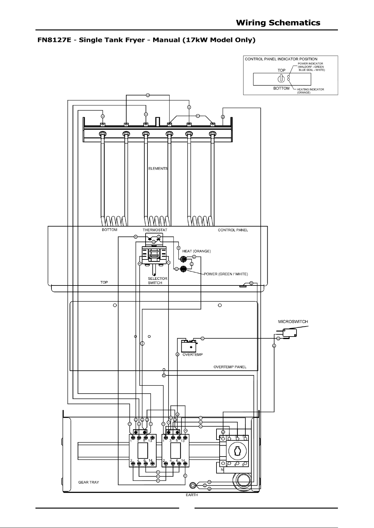
FN8127E Single Tank 17kW Model Only
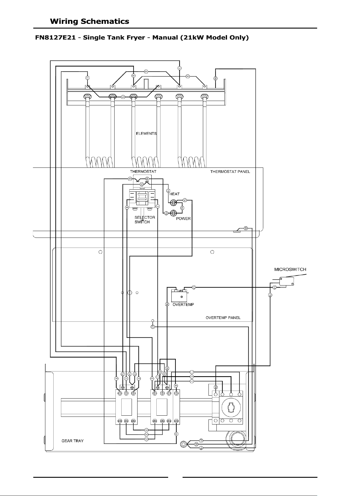
FN8127E21 Single Tank 21kW Model Only
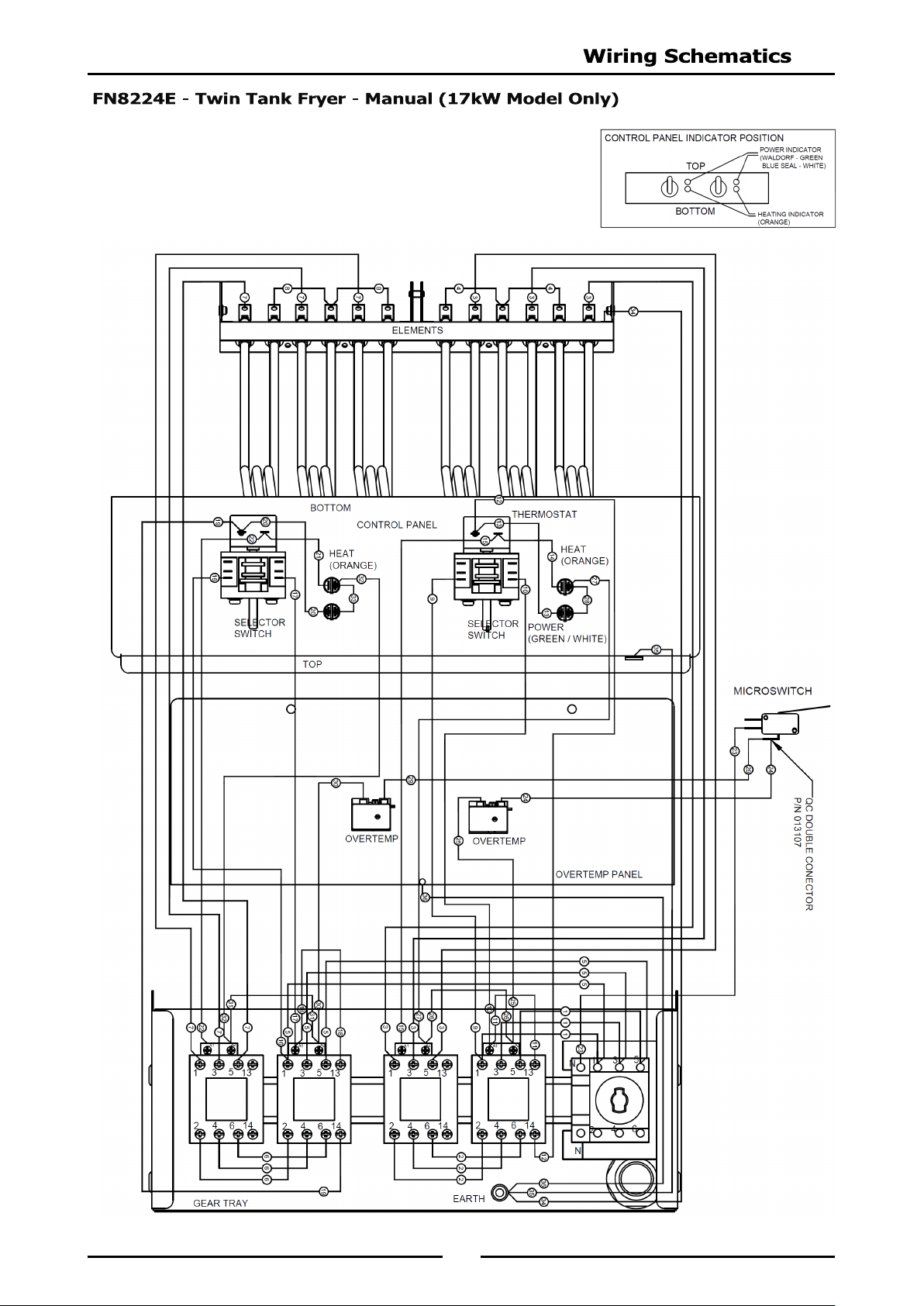
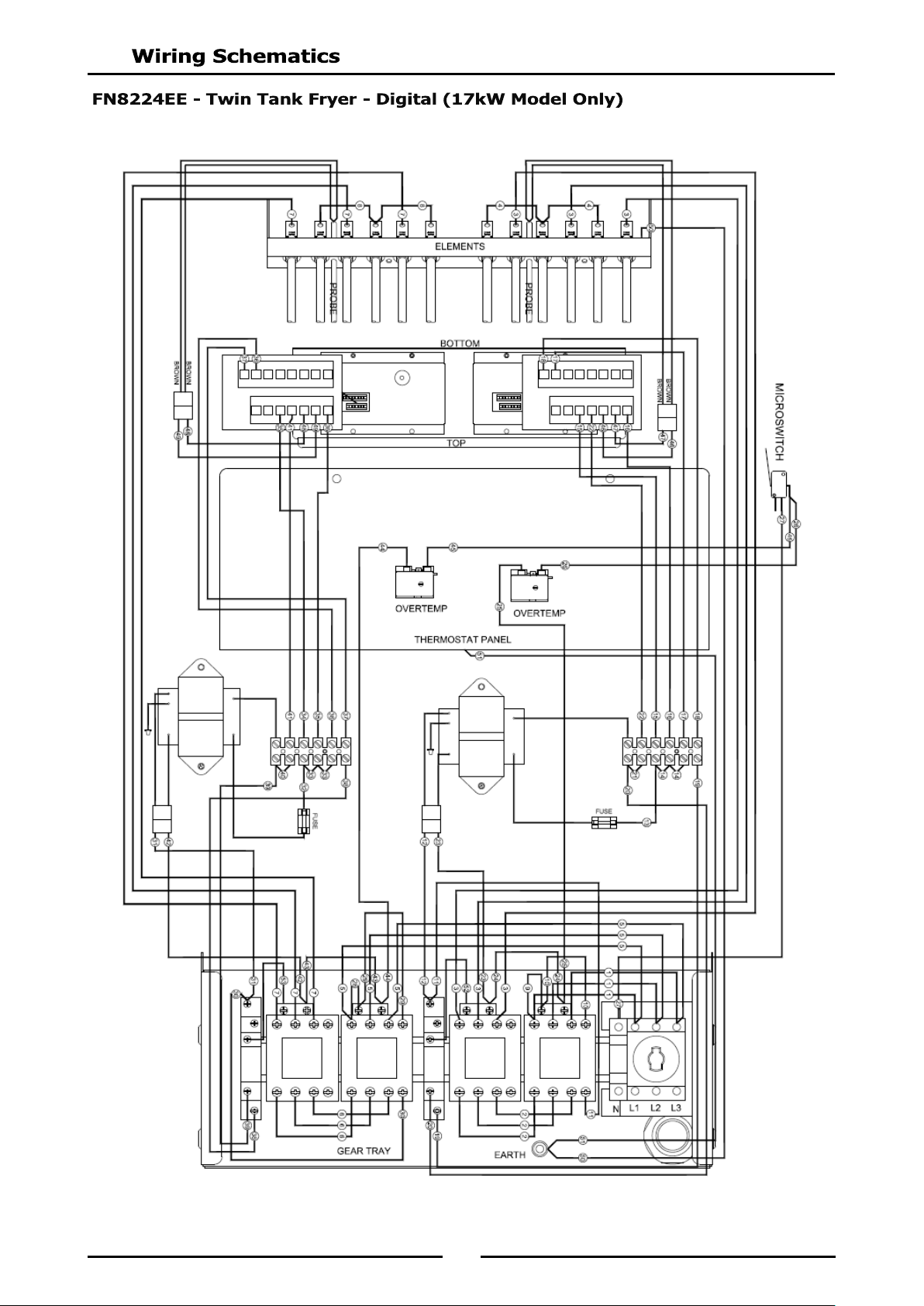
FN8224E Twin Tank 17kW Model Only
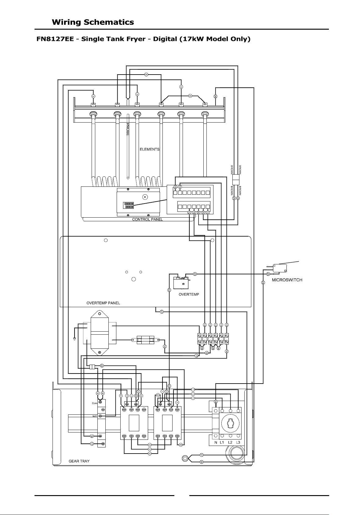
FN8127EE Single Tank 17kW Model Only
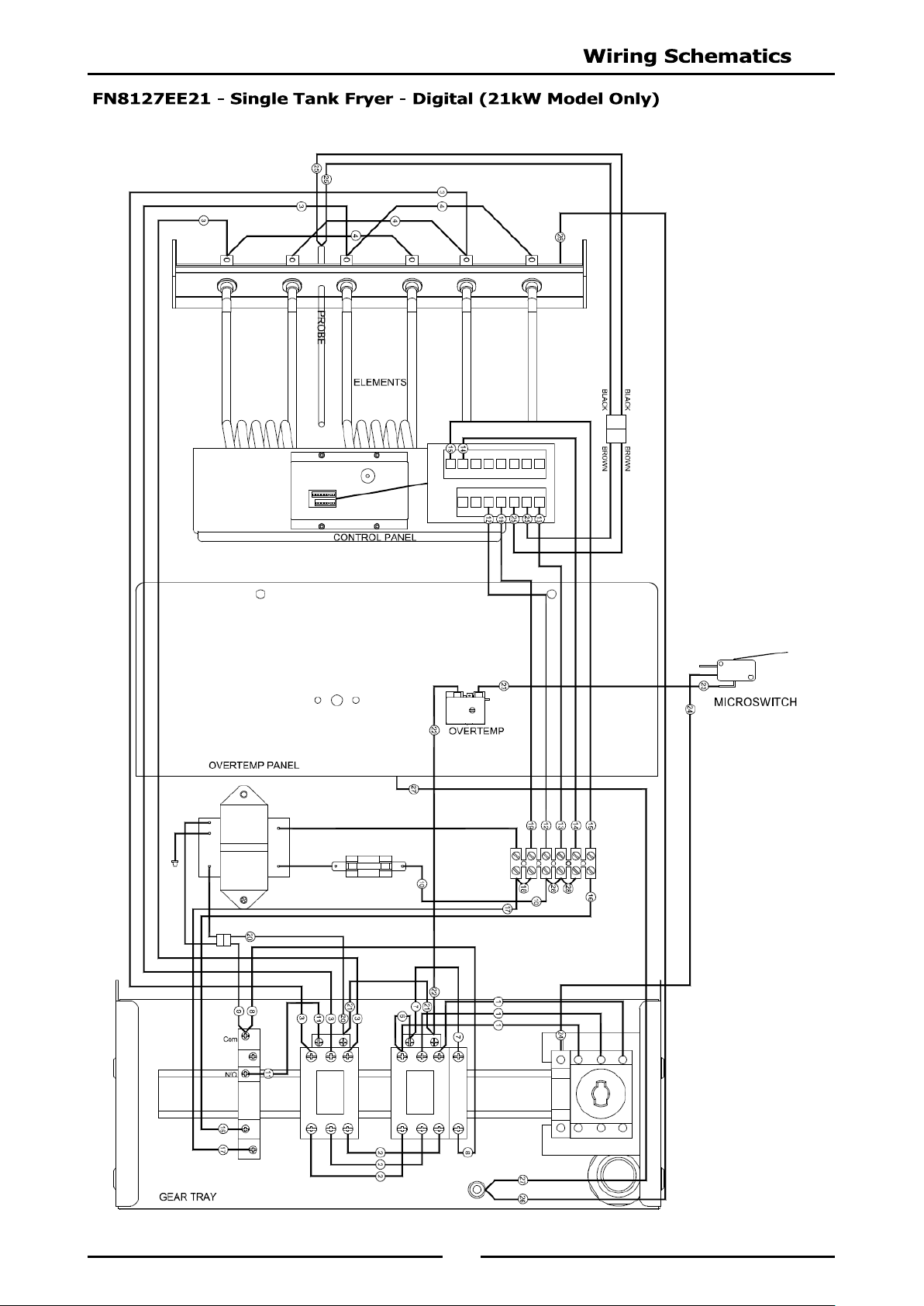
FN8127EE21 Single Tank 21kW Model Only
FN8224EE Twin Tank 17kW Model Only
Timing Mode.
Temperature Offset.
Temperature Display Mode.
Programming the Melt Cycle.
Setting the Temperature Units.
System Programmable Default Settings.
3
We are confident that you will be delighted with your WALDORF Electric Deep Fryer, and it will become a
most valued appliance in your commercial kitchen.
To ensure you receive the utmost benefit from your new Waldorf Electric Deep Fryer, there are two
important things you can do.
Please read the instruction book carefully and follow the directions given. The time taken will be well
spent.
If you are unsure of any aspect of the installation, instructions or performance of your appliance,
contact your WALDORF dealer promptly. In many cases a phone call could answer your question.
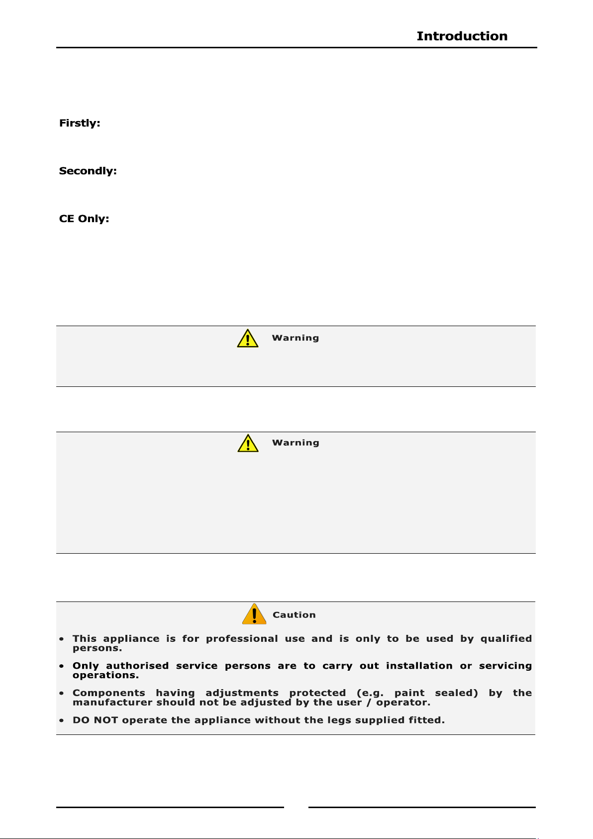
These instructions are only valid if the country code appears on the appliance. If the country code is
not shown, refer to the appliance supplier to obtain the technical instructions for adapting the appliance
to the conditions for use in that country.
THE OPERATOR MUST TAKE GREAT CARE TO USE THE EQUIPMENT SAFELY AND TO GUARD IT AGAINST THE RISK
OF FIRE.
THE APPLIANCE MUST NOT BE LEFT ON UNATTENDED.
IT IS RECOMMENDED THAT A REGULAR INSPECTION IS MADE BY A COMPETENT SERVICE PERSON TO
ENSURE CORRECT AND SAFE OPERATION OF YOUR APPLIANCE IS MAINTAINED.
DO NOT STORE OR USE GASOLINE OR OTHER FLAMMABLE VAPOURS OR LIQUIDS IN THE VICINITY OF
THIS OR ANY OTHER APPLIANCE.
DO NOT SPRAY AEROSOLS IN THE VICINITY OF THIS APPLIANCE WHILE IT IS IN OPERATION.
IMPROPER INSTALLATION, ADJUSTMENT, ALTERATION, SERVICE OR MAINTENANCE CAN CAUSE PROPERTY
DAMAGE, INJURY OR DEATH. READ THE INSTALLATION, OPERATING AND MAINTENANCE INSTRUCTIONS
THOROUGHLY BEFORE INSTALLING OR SERVICING THIS APPLIANCE.
4
FN[1]8127E 'Fast-Fri' Electric Fryer, Manual Control (Single Tank - 27ltr, 17kW).
FN[1]8127EE 'Fast-Fri' Electric Fryer, Digital Control (Single Tank - 27ltr, 17kW).
FN[1]8127E21 'Fast-Fri' Electric Fryer, Manual Control (Single Tank - 27ltr, 21kW).
FN[1]8127EE21 'Fast-Fri' Electric Fryer, Digital Control (Single Tank - 27ltr, 21kW).
FN[1]8224E 'Fast-Fri' Electric Fryer, Manual Control (Twin Tank - 24 ltr, 17kW).
FN[1]8224EE 'Fast-Fri' Electric Fryer, Digital Control (Twin Tank - 24 ltr, 17kW).
NOTE:
[1]: - Model Options;
- - Standard.
L - Low Back.
B - Bold Front.
LB - Low Back and Bold Front.
When connecting a this electric appliance to the mains supply, ensure that the following is carried out:-
n isolating
switch accessible during manual operation of the appliance.
The supply cord shall be protected against any mechanical or thermal damage.
Refer to the appropriate wiring standards for the size of cable that is to be supplied to an appliance for the
current drawn on that line.
Model
Power Supply
Total Power
Input
Amps
Voltage Type Frequency
L1 L2 L3
FN8127E / EE 400-415Vac 3 P+N+E 50 / 60Hz 17kW 23.6 23.6 23.6
FN8127E21 / EE21 400-415Vac 3 P+N+E 50 / 60Hz 21kW 29.2 29.26 29.2
FN8224E / EE 400-415Vac 3 P+N+E 50 / 60Hz 17kW 23.6 23.6 23.6
THIS APPLIANCE MUST BE EARTHED. IF SUPPLY CORD IS DAMAGED, IT MUST BE REPLACED BY A SUITABLY
QUALIFIED PERSON IN ORDER TO AVOID A HAZARD.
5
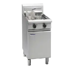
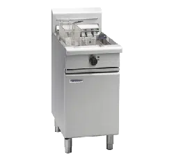
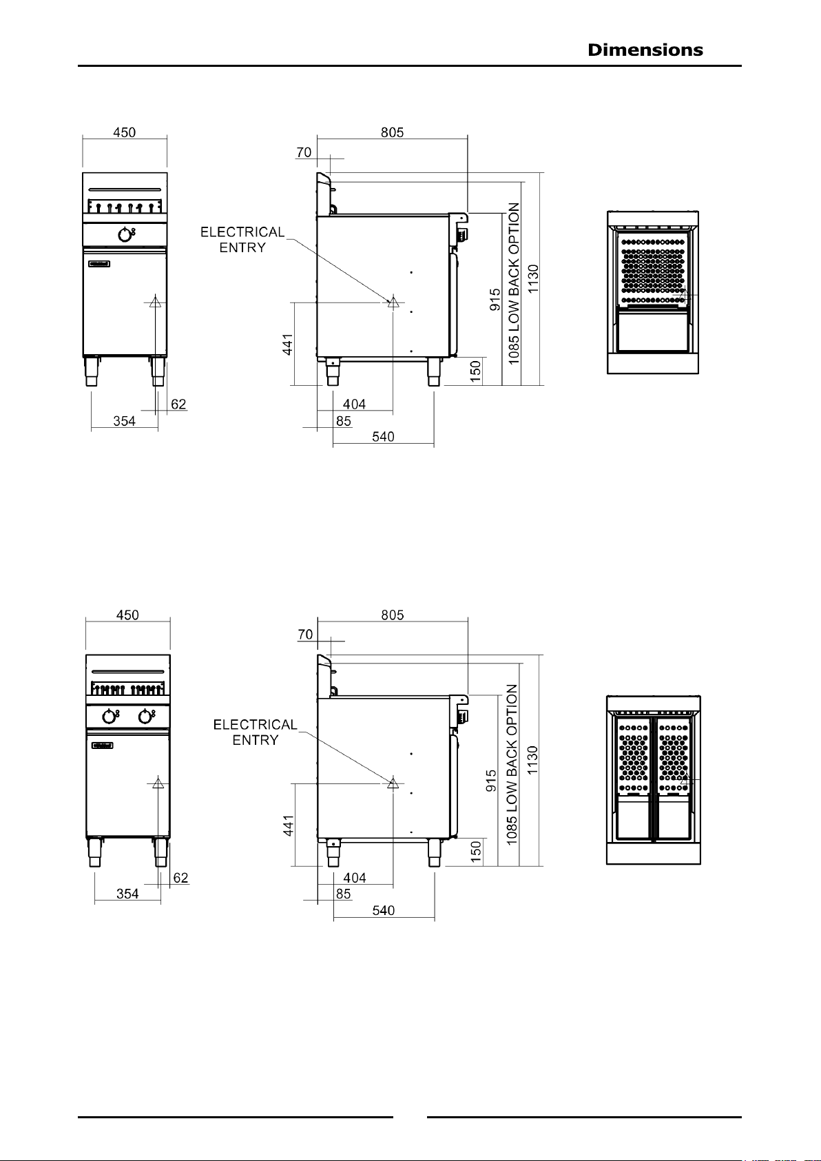
FN(L)8127E
FN(L)8224E
6
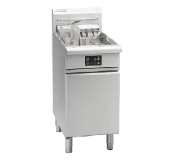
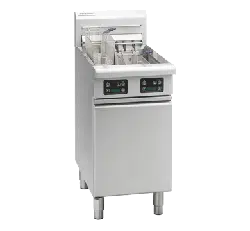
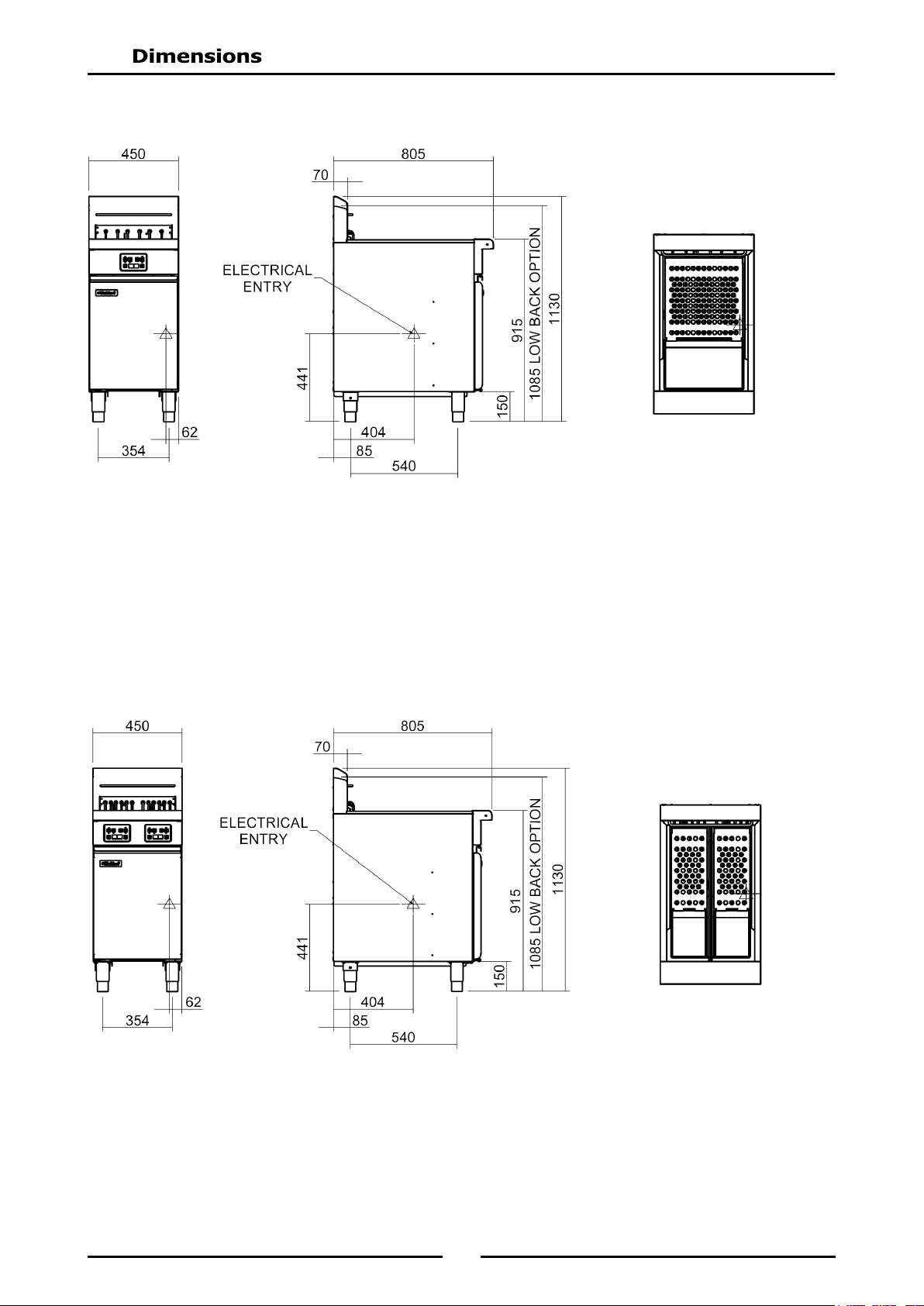
FN(L)8224EE
FN(L)8127EE
7
NOTE: It is most important that this appliance is installed correctly and that operation is correct
before use. Installation shall comply with local electrical and health and safety
requirements.
Waldorf Deep Fryers are designed to provide years of satisfactory service, and correct installation is
essential to achieve the best performance, efficiency and trouble-free operation.
This appliance must be installed in accordance with National installation codes and in addition, in
accordance with relevant National / Local codes covering health and safety, electrical and fire safety.
Australia / New Zealand AS / NZS3000 - Wiring Rules.
United Kingdom: BS 7671 - Requirements for Electrical Installations.
Installations must be carried out by qualified service persons only. Failure to install the
equipment to the relevant codes and manufacturers specifications shown in this section will
void the warranty.
Remove all packaging and transit protection from appliance including all protective plastic coating
from door outer panel and exterior stainless steel panels.
Check equipment and parts for damage. Report any damage immediately to carrier and distributor.
Report any deficiencies to distributor who supplied appliance.
Check available electrical supply is correct to as shown on rating plate on inside of access door.
Check the following parts have been supplied with appliance:
FN8127E / EE FN8224E / EE
Baskets 2 2
Lid 1 1
Drain Extension 1 2
1. Any appliance requires adequate clearance and ventilation for optimum and trouble-free operation.
Minimum installation clearances shown below, are to be adhered to.
2. Position the Deep Fryer in its approximate working position.
3. Legs (rear rollers - optional) must always be fitted. Ensure the legs / rollers are securely attached.
NOTE:
Only non-combustible materials can be used in close proximity to this appliance.
To allow easy operation, drainage and servicing of the appliance, a minimum of 600mm
clearance should be maintained at front of appliance.
This model is delivered completely assembled. Ensure that the legs are securely attached.
NOTE:
This appliance is fitted with adjustable feet to enable it to be positioned securely and level
on uneven floors. This should be carried out on completion of gas connection. Refer to
'Gas Connection Section'.
The rear leg housings on this appliance can also be fitted with rear rollers to enable the
appliance to be easily moved for positioning and cleaning purposes. If desired, these
rollers are supplied in the packaging, with tappliance. See overleaf for fitting instructions.
Optional Accessories (Refer to Replacement Parts List)
Plinth Kit. For installation details, refer to the instructions supplied with each kit.
Left / Right Hand Side 50mm 0mm
Rear 25mm 0mm
8
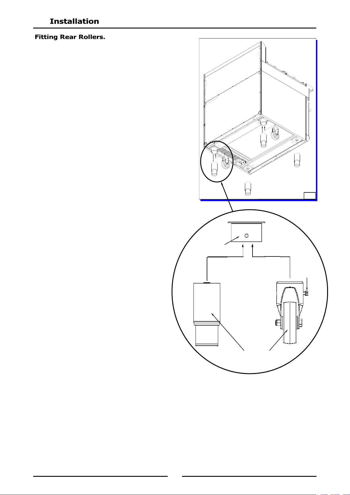
1. Raise the appliance from the floor by approx. 75mm,
using suitable lifting equipment (i.e. Palletiser / Forklift)
to allow rear adjustable feet to be removed.
2. Unscrew and remove both rear adjustable feet from
rear leg housings.
3. Fit rear roller to rear leg housing and align screw hole
in side of rear leg housing with threaded hole in rear
roller.
4. Secure the rear roller to the leg support with bolt
supplied and tighten bolt.
5. Fit second roller and tighten securing bolt.
6. Lower appliance back to the floor and adjust front
adjustable feet to level appliance.
Appliance
Base
Adjustable
Foot
Rear
Roller
Rear Leg
Housing
Roller
Locating Bolt
Fig 1
9
NOTE: ALL ELECTRICAL CONNECTIONS MUST ONLY BE CARRIED OUT BY A QUALIFIED
PERSON.
Each fryer should be connected to an adequately protected power supply and an isolation switch mounted
adjacent to, but not behind the fryer. This switch must be clearly marked and readily accessible in case of
fire.
1. Check the electricity supply is correct to as shown on the Rating Plate attached to the inside of the
access door.
2. Supply terminal connections are located at the lower front of the fryer.
3. Open the door and remove the service panel (6 screws) located behind the drain valve(s) to allow
connection access for electrical supply.
4. Bring the supply cable up through the grommet at the rear of the fryer and through the compression
type gland provided on rear of main electrical switchgear panel.
5. Connect mains supply to L1, L2 and L3 switch connections for 3 phases.
6. Connect neutral and earth conductors to the neutral and earth studs respectively.
7. For all connections ensure that the conductors are secure and appropriately terminated.
8. Tighten the cable gland to secure against tension on the cable.
NOTE:
This appliance must be grounded / earthed.
Fixed wiring installations must incorporate an all-pole disconnection switch.
1. Before leaving the new installation;
a. Check the following functions in accordance with the operating instructions specified in the
'Operation' section of this manual.
Check current draw and loading for the equipment. Refer to the Specifications section for
correct electrical requirements.
Check all connections are correct and that all cover panels have been re-fitted.
Check that the unit functions in accordance with the operating instructions.
Ensure the tank drain extension and this instruction manual are left with the appliance.
Ensure that all relevant details and contacts have been added to the front of this manual.
b. Check the thermostat operation by filling the fryer with oil / shortening to the appropriate oil 'FILL
LEVEL' mark and setting the thermostat to 180°C. Turn ‘On’ the fryer as shown in 'Operation
Instructions' in this manual.
c. Check the calibration of the thermostat once oil is up to temperature. If a discrepancy is found,
thermostat calibration should be referred to the supplier.
d. Ensure the operator has been instructed in the correct operation and shutdown procedure for this
appliance.
Initial Start-Up
Before using the fryer;
a. For first time use of the fryer and before using fryer for cooking product, fill the fryer with oil and
operate fryer for about 1 hour at Full Flame setting to remove any fumes or odours which may be
present in the new appliance.
b. Refer to Operation Section of this manual for details on how to operate the fryer.
2. This manual must be kept by the owner for future reference, and a record of Date of Purchase,
Date of Installation and Serial Number of Appliance is recorded and kept with this manual.
(These details can be found on the Rating Plate fitted to the inside of the access door and in
'Specifications' section of this manual.
NOTE:
If it is not possible to get the fryer to operate correctly, turn ‘Off’ electrical power and
contact a qualified service person. Appliance supplier will recommend a suitable person.
Make sure that the electrical supply is turned ‘Off’ before any service or maintenance work
is carried out.
10
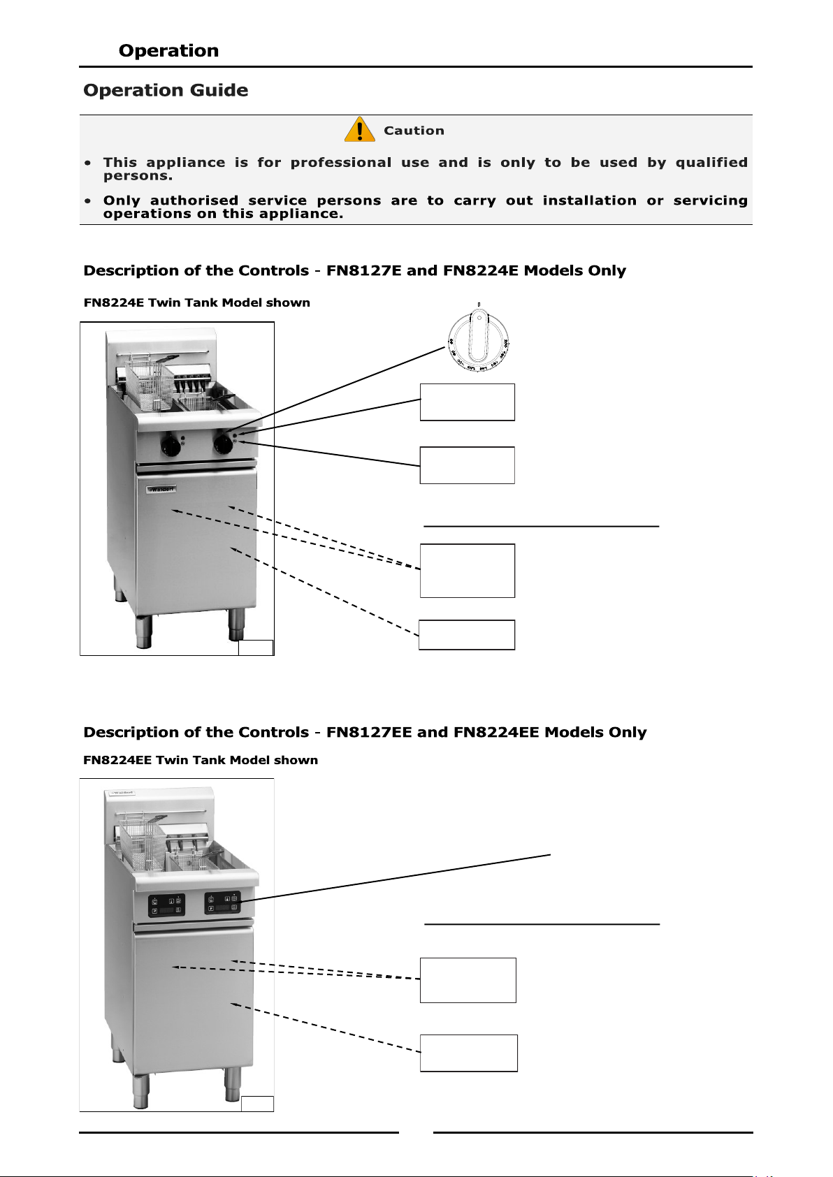
Temperature Control Knob
Temperature Graduations
60°C to 200°C.
Power ‘ON’ Indicator. (When
main power switch is ‘ON’).
Heating ‘ON’ Indicator. (When
thermostat is turned to a
selected temperature).
Operating the Reset Switches
resets power to the elements.
(One switch for each element.
Press to operate).
Turns power to the Fryer ‘ON’
and ‘OFF’. (Green Indicator
illuminates when switched
‘ON’).
Neon Indicator
(Green)
Neon Indicator
(Orange)
Temperature
Cut-out Reset
Switches
Located Behind Main Access Door
Mains Isolation
Switch
Fig 2
Electronic Controller
See description of Electronic
Controller overleaf.
Operating the reset switches
resets the elements.
(One switch for each element.
Press to operate).
Turns power ‘ON’ and ‘OFF’ to
the unit. (Green LED Indicator
illuminates when switched
‘ON’).
Mains Isolation
Switch
Fig 3
Temperature
Cut-out Reset
Switches
Located Behind Main Access Door
11
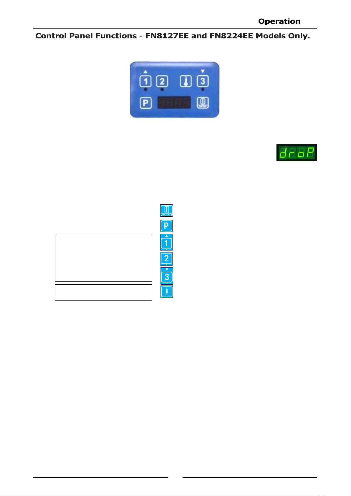
Each control panel comprises the following:-
One 4 digit, seven segment display with a 0.5” high, bright green LED display.
Three green LED indicator lights located under each of the 3 Timer Controls.
NOTE: Only one temperature
setting applies to all 3 timers.
The 3 Timer Keys on each control
panel can be used to program 3
different cook times for each tank.
6 Touch Control Keys;-
‘ON’ / ’OFF’ Key.
Programme Key (P).
Left Timer - ‘UP’ Key and LED Indicator Light.
Centre Timer - and LED Indicator Light.
Right Timer - ‘DOWN’ Key and LED Indicator Light.
Temperature Key (Thermostat).
12
The following Parameters can be changed in Controller Basic Programming Mode:-
Timer 1 - Cook Time Settings.
Timer 2 - Cook Time Settings.
Timer 3 - Cook Time Settings.
Cooking Temperature Setting.
Keypad ‘Lock - Unlock’ (Programming the Password Protection).
NOTE:
Each Timer Key on the control panel can be individually programmed with a different cook
time.
The user cannot enter Basic Programming Mode whilst a timer is running. An alarm will
sound indicating the key press, but access to programming mode will be blocked.
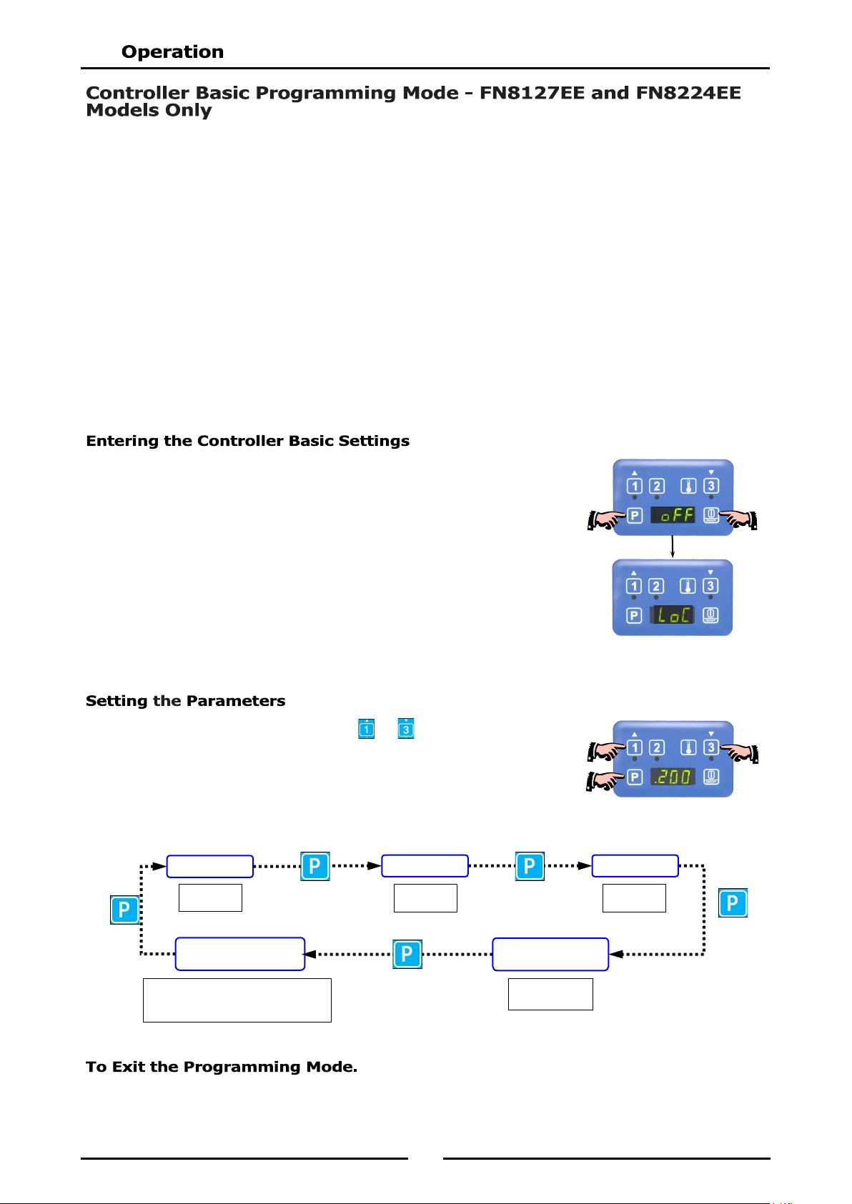
1. To enter ‘Programming Mode’, press ‘ON / OFF’ key to turn ‘ON’
the control panel.
2. Press Programme Key ‘P’ to access the parameter setting required.
a. If ‘LoC’ is displayed, control panel is locked which will prevent
any accidental change to the operating mode.
b. To access parameters, whilst ‘LoC’ is displayed on screen,
enter the passcode ‘1 1 3 3’.
1. To change the settings, press either or Key until the value
required is shown on the display.
2. Press Programme Key ‘P’ to confirm new value and the change will
be accepted. Display will step on to the next parameter.
To exit Programming Mode, press and hold Programme Key ‘P’ for approximately 3 seconds, or do not
press any key for 2 minutes. The display will revert to ‘Idle Mode’.
TIMER 1
COOK TEMPERATURE
SETTING
KEYPAD
‘LOCK’ - ‘UNLOCK’
Min 0.01
Max 99.59
Min 88°C
Max 193°C
If set to ‘LoC’, password is required
to change any of these settings.
Password is 1,1,3,3.
TIMER 3
TIMER 2
Min 0.01
Max 99.59
Min 0.01
Max 99.59
13
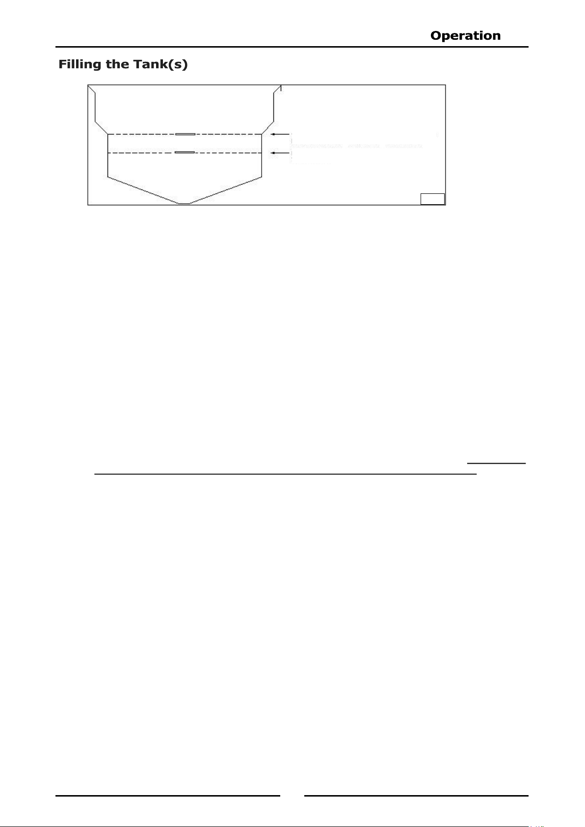
NOTE: WALDORF 'Deep Fryers’ can be used with both oil and shortening.
1. Before filling the tank, always check that the drain valve behind the door is closed. A locking slide is
provided on these valves and this should always be in the locked position during use.
2. Ensure that the elements are swung down into the tank(s).
OIL - Carefully fill the fryer tank until the lower ‘Fill Level’ mark is reached.
Set the thermostat to the required operating temperature, the oil will expand as heated and will
reach the upper level mark when the oil is hot (180 - 190°C).
The FN8127 single tank fryer will hold 27 to 29 litres of oil.
The FN8224 twin tank fryer will hold 14 litres of oil per pan.
SHORTENING - Ideally shortening should be pre-melted prior to putting it into the tank. This is normally
done in a suitable vessel on a boiling table burner(s). The liquefied shortening can then be poured
into the tank until it reaches the 'FILL LEVEL' mark.
The FN8127 single tank fryer will hold 22 - 23kg of shortening.
The FN8224 twin tank fryer will hold 11kg of shortening per tank.
Pre-Heating
NOTE: When pre-melting shortening, only heat the shortening until it is just liquefied. Do not bring
the shortening up to high temperature as handling of hot shortening is dangerous.
If it is not possible to pre-melting the shortening, carefully cut shortening into small pieces and
pack below, all around and above the elements, ensuring that the element can fully lower to
operate the element tilt microswitch, otherwise the fryer will not operate.
FN8127E and FN8224E Only;- Set the tank control therm ostat to 120°C and sw itch
‘ON’ the appliance for 30 seconds and then ‘OFF’ for 1 minute. Repeat the cycle until all the
shortening is melted enough to apply full power to the heating elements. To speed up this
process, break up the shortening and stir carefully during the melting process.
Add more shortening until the tank is filled to the level marked on the tank side. Refer to Fig 4
above.
NOTE: Running the elements continuously will cause the shortening in contact with the element to
overheat, resulting in premature oil breakdown. Never allow the shortening to smoke whilst
melting as this indicates that the temperature is too high. If the shortening starts smoking,
increase the ‘Off’ intervals of the elements.
Fig 4
CORRECT LEVEL FOR FRYING MEDIUM WHEN
AT FRYING TEMPERATURE.
CORRECT LEVEL FOR FRYING MEDIUM WHEN
COLD.
14
1. Turn ‘ON’ mains power at the mains supply.
2. Turn ‘ON’ mains isolator switch located behind the front access door. Green neon indicator will
illuminate to indicate that there is mains power to the fryer.
3. Set the tank control thermostat to the temperature required. Orange neon indicator will illuminate
to indicate that the heating elements are ‘On’.
4. When oil in tank reaches the set temperature, Orange neon will extinguish to indicate that fryer is up
to the selected temperature.
5. To turn ‘OFF’ the fryer, open the front access door and turn the mains Isolator Switch to the ‘OFF’
position.
6. Turn ‘OFF’ mains power at mains supply.
THE OPERATOR MUST TAKE GREAT CARE TO USE THE EQUIPMENT SAFELY AND TO GUARD IT AGAINST THE RISK
OF FIRE.
DO NOT LEAVE THE FRYER UN-ATTENDED DURING OPERATION.
DO NOT REPLENISH THE OIL (FRYING MEDIUM) IN THE FRYER WHEN THE FRYER IS HOT.
DO NOT OVER FILL THE OIL (FRYING MEDIUM) IN THE FRYER ABOVE THE TOP LEVEL MARK.
DO NOT ALLOW THE OIL (FRYING MEDIUM) IN THE FRYER TO FALL BELOW THE LOWER LEVEL MARK.
DO NOT ALLOW THE OIL (FRYING MEDIUM) IN THE FRYER TO OVERHEAT.
DO NOT INTRODUCE WET FOOD OR WATER INTO THE HOT OIL (FRYING MEDIUM).
DO NOT USE FLAMMIBLE SOLVENTS AND CLEANING AIDS ON OR IN CLOSE PROXIMITY TO THE FRYER
WHILST THE FRYER IS STILL HOT.
15
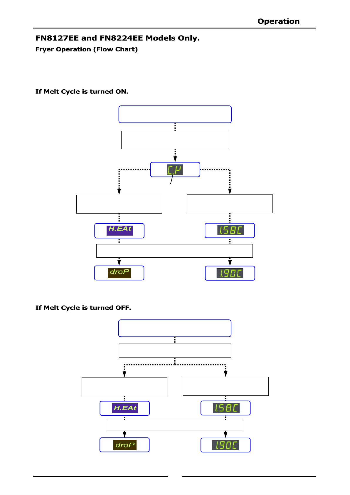
TURN ON FRYER
Press ON / OFF key to turn ‘ON’ Control Panel.
When oil is Up To Temperature, display will show the following.
If ‘t - 1’ selected in Advanced
Program Settings, display will show
Actual Temperature of oil.
Neon Dot Indicates Heating is‘ON’
If Melt cycle is active, display will show the
following. Refer to Controller Advanced
Programming Mode for available settings.
If ‘t - 0’ selected in Advanced
Program Settings, display will show
the following.
Refer to ‘Controller Basic Programming Mode’ at the start of this section for the basic programmable
settings for the controller.
Refer to the ‘Controller Advanced Programming Mode’ section for controller advanced programming.
Fryer can now be used without using the Timers, if required.
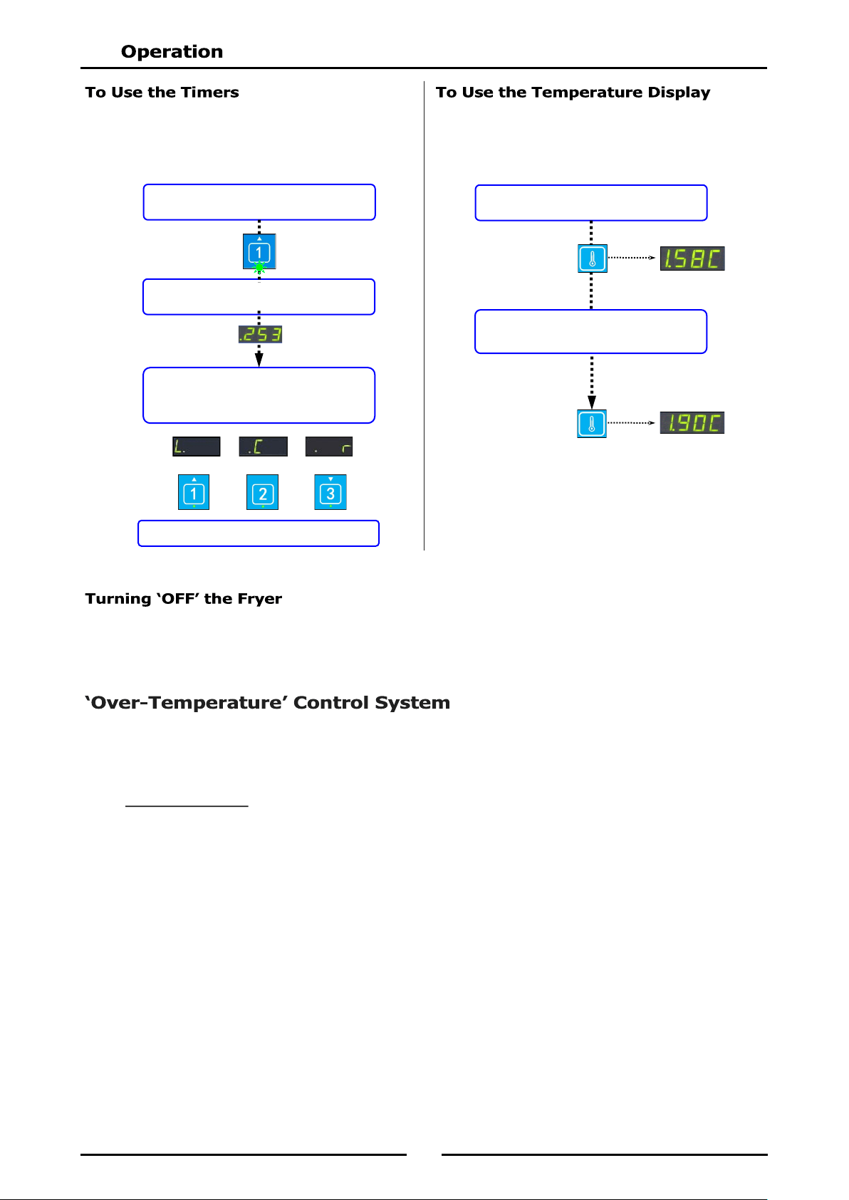
TURN ON FRYER
Press ON / OFF key to turn ‘ON’ Control Panel.
When oil is up to temperature, display will show the following.
If ‘t - 1’ selected in Advanced
Program Settings,
Actual Temperature of oil is displayed.
If ‘t - 0’ selected in Advanced
Program Settings, display will show
the following.
Display will show the following. Refer to Controller
Advanced Programming Mode for settings.
Fryer can now be used without using the Timers, if required.
16
Press Timer 1, 2 or 3 as required.
LED beneath timer will flash continuously.
On completion of frying, beeper will sound
and display will show which timer has
completed frying.
Left Centre or Right
Press Timer Key to cancel Beeper and Timer
Press Temperature Key.
Display shows Actual Temperature.
1. Press the ‘On /Off’ Key on the control panel.
2. Turn ‘Off’ the power supply at the mains supply.
These fryers have been fitted with a ‘Fail Safe Over Temperature Safety Cut-Out’ which will protect the oil /
fat from excessive temperature if the thermostat control should fail. The power light will turn ‘Off’ if the
over temperature control has been triggered. The twin tank fryer (FN8224E) has an individual ‘Fail Safe
Over Temperature Safety Cut-Out’ for each tank.
Over-Temp Control
The over-temp thermostat is mounted behind the transformer panel, behind the access door and its
sensing bulb is located alongside the thermostat (E and EE Models).
This control is set for approx. 225-235°C oil cutout temperature. To reset the 'Overtemp Control',
allow the oil to cool down to approx 160-180°C then operate the red switch behind the access door.
The power light will then turn ‘On’.
NOTE: On dual tank models, if either 'Over-Temperature Control' is triggered, a fault exists in the
main thermostat and this must be reported and repaired. For temporary operation, Model
FN8127EE is fitted with a backup thermostat.
Press Temperature Key again,
within 3 seconds.
Display shows Set Temperature.
Display will count down time to
completion of frying.
NOTE: Refer to ‘Basic Programming Mode’ for
information on how to set the Timer
Pre-Set times.
NOTE: Refer to ‘Basic Programming Mode’ for
information on how to set the Cooking
Temperature.
17
To achieve the best results, cleaning must be regular and thorough and all controls and mechanical parts
checked and adjusted periodically by a competent serviceman. If any small faults occur, have them
attended to promptly. Don't wait until they cause a complete breakdown. It is recommended that a service
check is conducted every six months.
Clean the fryer regularly. A clean fryer looks better, will last longer and will perform better.
NOTE:
DO NOT use sharp scrapers, strong solvents, abrasive or caustic detergents as they could
corrode or damage the fryer.
Ensure that any detergent or cleaning material has been completely removed after each
cleaning.
To keep your fryer clean and operating at peak efficiency, follow the procedures shown below:-
1. At the end of each day or at the end of each shift, if frying schedule is heavy, frying medium should
be drained and filtered into a receptacle.
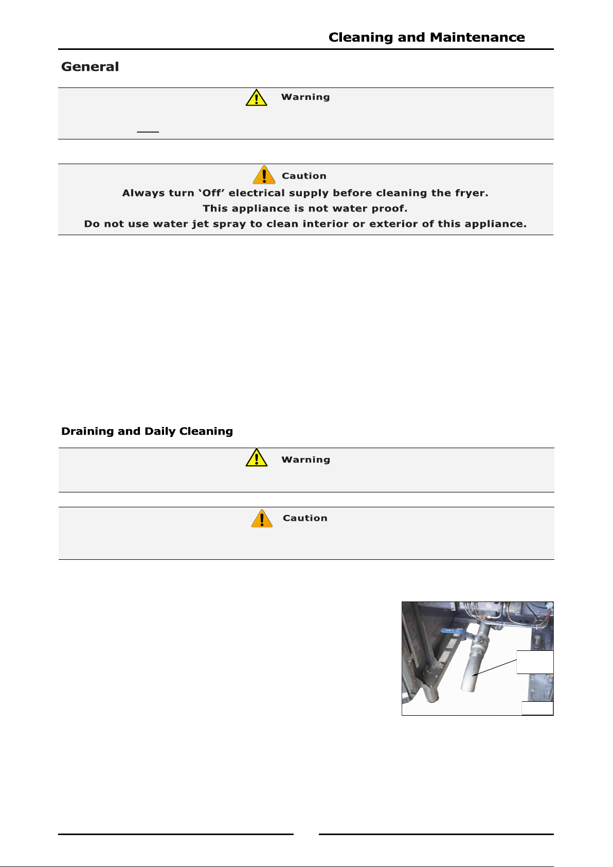
2. Always filter the fryer when the cool zone under elements is hot
and liquid. A cold fryer heated up won't drain, because frying
medium in this zone will remain hard if using solid fat / oils.
3. Screw the drain extension pipe onto the end of the drain valve
(see Fig 5) and position a suitable container and filter under the
drain extension pipe.
DO NOT USE FLAMMIBLE SOLVENTS AND CLEANING AIDS ON OR IN CLOSE PROXIMITY TO FRYER WHILST
FRYER IS STILL HOT.
Never drain the fryer with power or elements turned ‘ON’
Always switch ‘OFF' fryer before draining or re-filling tank.
DO NOT ATTEMPT TO MOVE FRYER WHILST FRYER IS FULL OF OIL.
Fig 5
Drain
Extension
Pipe
18
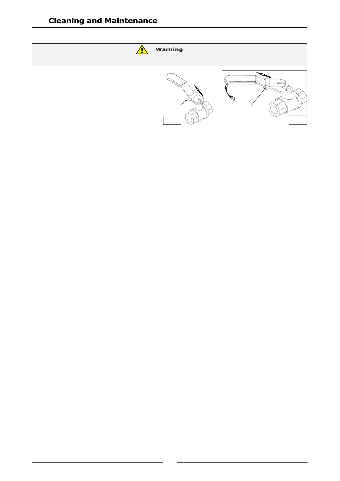
Opening the Drain Valve
a. Lift the locking slide on valve handle
(Fig 6) to release the valve.
b. While holding the locking slide in the
withdrawn position, rotate handle
anticlockwise (Fig 7) to open the
valve.
c. When the valve is closed, the locking
slide will drop down over the locking
valve to prevent accidental opening of
the valve, as shown in Fig.6.
4. Do not empty total fryer contents into one large container, as this will be dangerous and may be
difficult, when lifted up, to pour hot oil back into the fryer tank.
5. Slip a muslin or other suitable filter bag over the end of the drain valve. Crumbs will be caught in
the bag but the frying medium will strain freely through into the container.
6. Open the drain valve slowly to minimise splashing, and take care not to overfill the container.
7. When tank has been drained, use a ladle or small pan with a handle and dip into the hot frying
medium from the container and pour around the sides and bottom of the fryer tank to wash out
crumbs and particles adhering to the tank.
8. Continue to dip and pour until all crumbs and particles are washed down and into the filter bag.
9. Open the drain valve fully and check for any particles or crumb residue lodged in the valve. Clean
out the valve with a stiff nylon brush. Do not use a wire brush as this may damage the valve
seating and will eventually lead to valve leakage. If the obstruction cannot be removed with a
brush, use a wooden probe to dislodge the obstruction.
10. Wipe all exterior panels with a cloth dampened with detergent and rinse off any residue with clean
warm water.
11. Clean the Control Panel with a damp cloth lightly moistened with a solution of water and a
commercial quality foodservice approved detergent.
12. Once the daily cleaning is completed, close the drain valve and pour the frying medium back into the
fryer tank.
HOT OIL WILL BURN - DO NOT RUSH THIS JOB.
Fig 7
Fig 6
Locking Slide
Locking
Slide
19
NOTE: If fryer usage is very high, we recommend that the weekly cleaning procedure is carried out
more frequently.
1. Proceed to drain and filter the tank, as shown in 'Daily Cleaning'. Do not refill the tank with frying
medium until the tank has been cleaned as shown below.
2. Fill the fryer with cold water to the normal fill level and add a high quality commercial cleaner that
has been specifically formulated for fryers.
All purpose cleaners are not recommended
.
NOTE: Never use a caustic or lye solution, as this will leave a fat destroying film on the tank.
3. Ensure that the elements are lowered into the tank. Switch ‘ON’ the power and heat the water to
approximately 80-90°C.
4. Clean the fryer baskets at the same time by immersing them in the cleaning solution. Allow the
fryer to soak for 5-10 minutes or as directed on the cleaner instructions. Remove the baskets and
switch ‘OFF’ the fryer.
5. Scrub the baskets and fryer tank lightly, but vigorously with a stiff nylon bristle brush to remove any
remaining deposits. DO NOT use a wire brush, as this will scratch the sides of the tank.
6. Empty the fryer and rinse thoroughly with water. Use a 1 part vinegar to 15 parts water solution to
rinse the tank and neutralise any cleaner residue. If this proves unsuitable for the cleaner being
used, use a weaker solution of up to 1 part vinegar to 25 parts water.
7. Rinse the tank thoroughly with water, drain and dry.
8. Refill the tank with new filtered frying medium.
Stainless Steel Surfaces
a. With the tank(s) drained, cleaned and dried as shown above, clean the exterior surfaces of the
fryer with hot water, a mild detergent solution and a soft cloth.
b. Dry all components thoroughly with a dry cloth and polish with a soft dry cloth.
c. To remove any discolouration, use an approved stainless steel cleaner or stainless steel wool.
Always rub in the direction of the grain.
NOTE: All maintenance operations should only be carried out by a qualified service person.
To achieve the best results, cleaning must be regular and thorough. All controls and mechanical parts
should be checked and adjusted periodically by a qualified service person. If any small faults occur, have
them attended to promptly. Don't wait until they cause a complete breakdown. It is recommended that
the appliance is serviced every 6 months.
20
This section provides an easy reference guide to the more common problems that may occur during the
operation of your equipment. The fault finding guide in this section is intended to help you correct, or at
least accurately diagnose problems with your equipment.
Although this section covers the most common problems reported, you may encounter a problem not
covered in this section. In such instances, please contact your local authorised service agent who will
make every effort to help you identify and resolve the problem. Please note that the service agent will
require the following information:-
Model Code and Serial Number of the appliance. (both can be found on the Rating Plate
located on appliance).
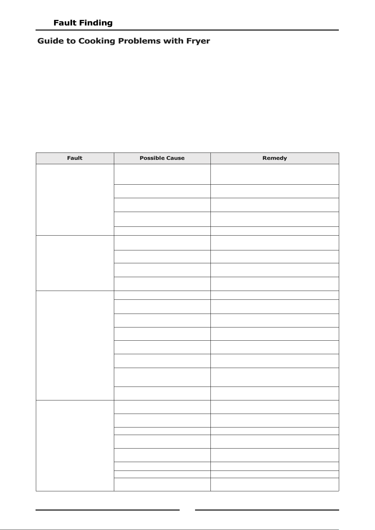
Frying Medium Foaming.
Presence of soap or detergent residue
from cleaning the tank.
Rinse fryer thoroughly three times with clean water.
Ensure fryer is perfectly dry before re-filling with
frying medium.
Excessive breakdown of frying medium. Add fresh frying medium daily to replace contents
every 3-5 days.
Continual frying of food with excess
moisture.
Remove excess moisture from foods to be fried.
Continued overheating of oil. Check thermostat setting. Turn down heat to around
120°C (Standby) when use is quiet.
Overloading. Maintain 1-8 ratio of food to frying medium.
Gumming.
Heating frying medium too rapidly. When charging fryer or starting up, melt frying
medium gradually.
Continued overheating of the frying
medium.
Check thermostat setting with a thermometer or
thermocouple.
Frying oil broken down. Check amount of fresh frying medium added to fryer
to be sure 'turnover' is adequate.
Using wrong cooking frying medium. Some frying mediums form gums when used in a deep
fryer. e.g safflower oil.
Greasy Foods.
Frying at too low temperatures. Increase temperature and check thermostat setting.
Inadequate preparation of food. Be sure foods (especially potatoes) are 'cured'
correctly.
Excessive quantities of breading or
batter.
Remove surplus breading or batter.
Placing food in frying medium direct
from the freezer.
Allow frozen foods to thaw before frying.
Surplus moisture in and on surface of
food.
Drain and dry foods before frying.
Frying medium in advanced stages of
breakdown.
Discard 'old' frying medium and refill fryer with new
frying medium.
Use of dripping or other unrefined oil. Due to low smoking point, cooking in these oils at
lower temperatures will result in greater oil absorption
by the food.
Using the wrong kind of cooking oil. Always use a completely refined and deodorised
cooking oil.
Inadequate frying oil turnover. Adjust procedures to fry more food in fryer to increase
turnover.
Rapid Oil Breakdown.
Oil overheating. Check thermostat setting with a thermometer or
thermocouple.
Contamination. Filter or strain the oil daily.
Poor cleaning procedures. Clean fryer daily or at least once a week and rinse
thoroughly. Dry fryer before use.
Presence of copper or brass in the fryer
equipment.
Remove all copper or brass fittings from contact with
the oil.
Overloading the fryer. Maintain 1-8 ratio of food to frying oil.
Food excessively moist. Drain and dry the food before frying.
Oil overheating on ‘Standby’ mode. Reduce temperature of frying oil between 93°C during
idle (‘Standby’) periods.
21
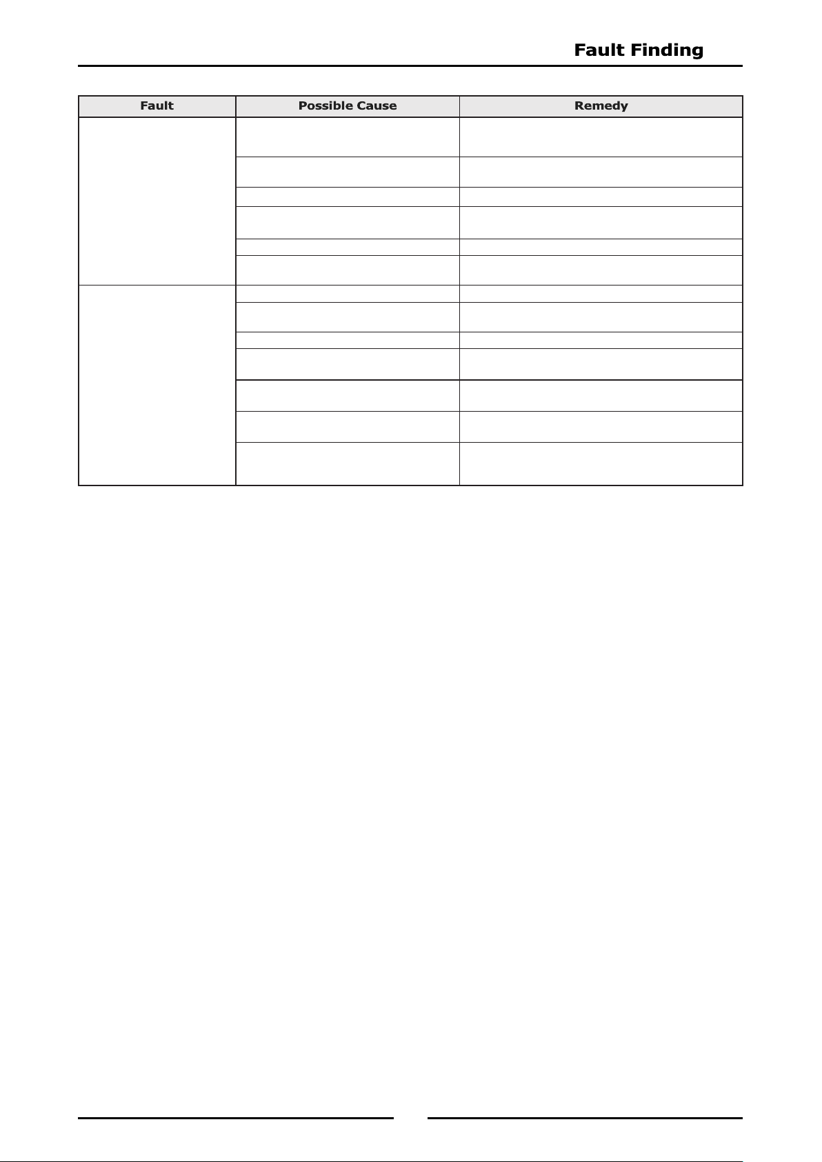
NOTE: Excessive usage of oil is an indication of high absorption of oil into the food. This is a
function of temperature and character of the goods being fried - NOT due to type of oil
being used (unless refined oils are being used). Any variation in the apparent life of the oil
is always due to one or more of the causes mentioned above.
Oil Smoking.
Insufficient turnover of oil. Maintain a minimum quantity of oil in fryer for more
rapid turnover or increase the quantity of food fried in
fryer. Replace with fresh oil every 3 to 5 days.
Continual frying with excess moisture on
food.
Drain foods before frying, pat food dry.
Contamination of oil. Filter or strain daily to remove contaminants.
Overheating of oil. Check thermostat setting with a thermometer or
thermocouple.
Rapid breakdown of oil. Use a stable frying oil.
Use of unrefined oils. Dripping smokes at lower temperature than refined
and deodorised oils.
Darkening of Oil.
Presence of salt on the food. Salt foods after frying and away from the fryer.
Foods dipped in batter high in egg yolk. Reduce egg content of batter, replace part egg with
milk.
Contamination of oil. Filter or strain the oil daily to remove contaminants.
Poor cleaning practice. Clean fryer at least weekly or each day in cases of
heavy usage. Ensure fryer is perfectly dry before use.
Overheating of oil. Check thermostat setting with a thermometer or
thermocouple.
Insufficient oil turnover. Top up daily to replace the contents of fryer in 3 to 5
days.
Cooking foods with high sugar levels. At the end of the season, potatoes are usually high in
reduced sugars. When fried, they will darken quickly
and colour the oil.
22
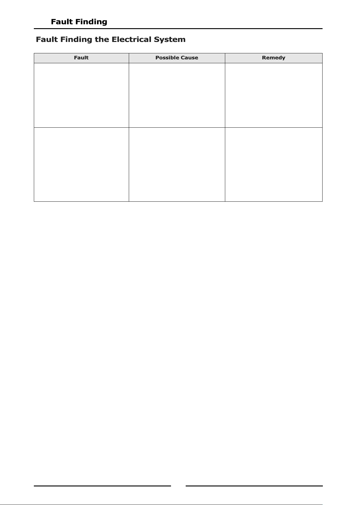
Elements do not Heat Up.
Check mains power is supplied to the unit
and that a circuit breaker or fuse has not
tripped / blown.
Check element is flat and that the tilt
microswitch is closed.
Check thermostat setting is correct and
that control knob is set to 'ON' position.
Turn ‘On’ power. Reset circuit breaker or
replace blown fuse.
Adjust microswitch so that the microswitch
is activated when element is fully down in
the flat (cooking position).
Replace the thermostat.
Call service provider.
Over-Temperature Thermostat Cuts
Out.
Over-temperature thermostat faulty.
Control thermostat not maintaining set
temperature.
a. Thermostat out of calibration.
b. Thermostat does not open on
temperature rise.
Thermostat opens on temperature rise but
electrical contactor does not respond.
If overtemp cuts out below 220ºC, replace
over-temperature thermostat.
Call service provider.
Check continuity through thermostat leads,
on temperature rise. If circuit does not
open, replace the thermostat.
Call service provider.
Check electrical connections are correct.
Call service provider.
23
24
25
26
27
28
29
The following Parameters can be accessed and adjusted in the Advanced Programming Mode:-
Timing Mode (Straight or Flexi cook time).
Temperature Offset (Calibration Setting) -14° to +14°.
Temperature Display Mode (Temp display or prompt display).
Programming the Melt Cycle.
Setting the Temperature Units (either °C or °F).
System Programmable Default Settings.
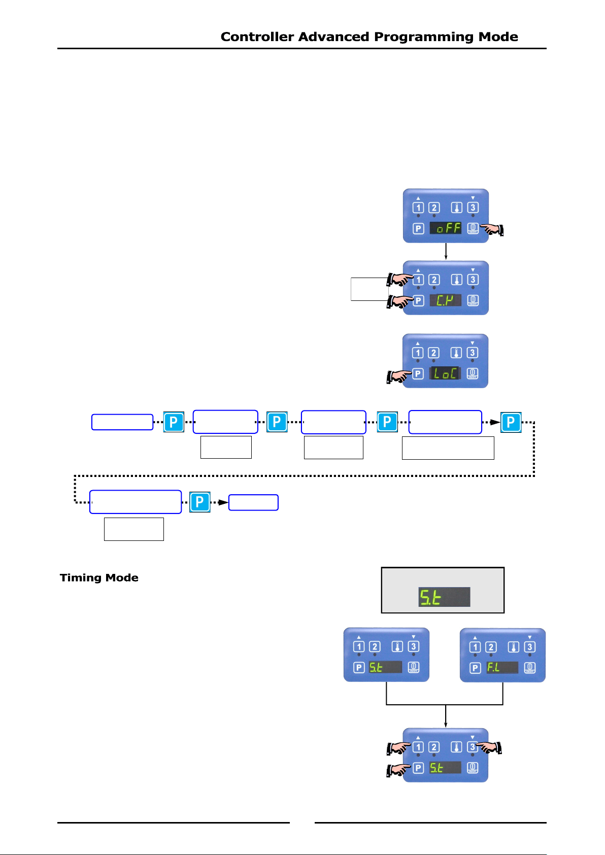
1. Press the ‘ON / OFF’ Key to turn ‘ON’ the fryer
controller.
2. Press Programme Key ‘P’ and ‘Timer 1’ Key together to
enter ‘Advanced Programming Mode’.
3. If ‘LoC’ is displayed, passw ord protection is turned ‘ON’
and control panel is locked. Unlock the control panel, refer to
‘Controller Basic Programming Mode’ - ‘Entering the Controller
Basic Settings’, and repeat from Item 2 above.
1. One of the following options will display:-
Straight Cook Time
Straight cook time refers to real time cooking.
Flexible Cook Time
Cook time can be automatically adjusted to
compensate for size of load being cooked.
2. To change ‘Timing Mode’, press either ‘Timer 1’ or
‘Timer 3’ Key.
3. Press Program ‘P’ Key to confirm options, the change
will be accepted and display will step on to
‘Temperature Offset’ parameter.
Press
Together
Factory Default Settings
TIMING MODE
TEMPERATURE
OFFSET
TEMPERATURE
DISPLAY MODE
PROGRAMMING
THE MELT CYCLE
SETTING THE
TEMPERATURE UNITS
IDLE MODE
from
-14° to +14°
either
't -1’
or
't -0’
either
‘CY L’, ‘CY.S’ or 'CY o’
either
'°F’ or '°C’.
30
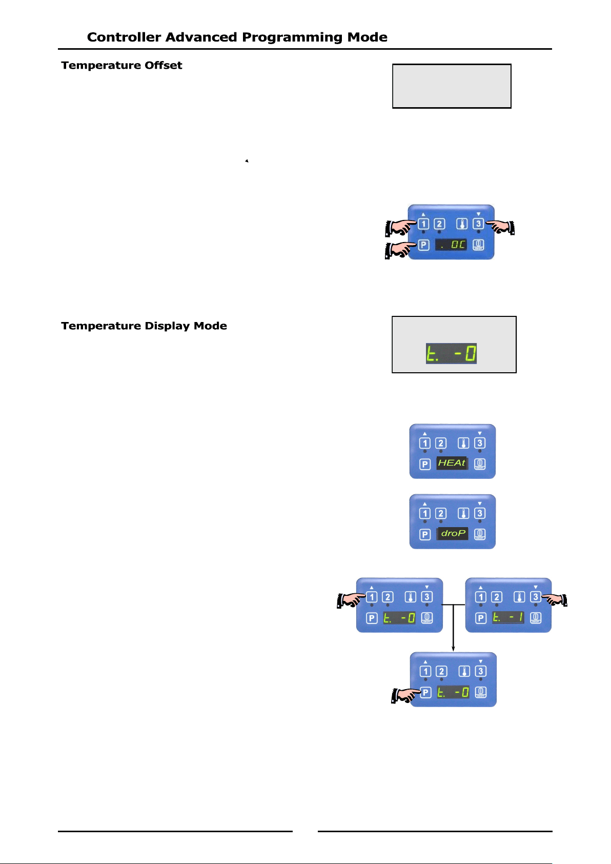
The display temperature can be adjusted by between -14° to +14°.
To Calibrate the Control Temperature
Set control temperature to 170°.
Measure the oil temperature that the control is cycling at.
If oil temperature is
higher
than the reading shown on the control panel, enter a
positive
value of
the difference between the oil temperature and the set temperature (170° + difference).
If oil temperature is
lower
than the reading shown on the control panel, enter a
negative
value of
the difference between the oil temperature and the set temperature (170° - difference).
1. Temperature offset will appear on the screen.
2. To change temperature offset option, press either ‘Timer 1’
or ‘Timer 3’ Key to change selection.
3. Press Program Key ‘P’ to confirm the change and the display
will step on to ‘Temperature Display’ parameter.
Temperature display can be set for either of two display modes:-
't - 1’ - Display will show oil temperature as an actual temperature.
’t - 0’ - Display will show one of the following temperature status;
‘HEAt’ - Awaiting for fryer to heat up to set temperature.
‘droP’ - When fryer is within
10° of set temperature to
indicate that fryer is ready for loading.
1. One of the following options will display:-
2. Press either ‘Timer 1’ or ‘Timer 3’ Key to select
option required.
3. Press Program Key ‘P’ to accept the change and display will
step on to the ‘Programming the Melt Cycle’ parameter.
Factory Default Settings
Factory Default Settings
O°
31
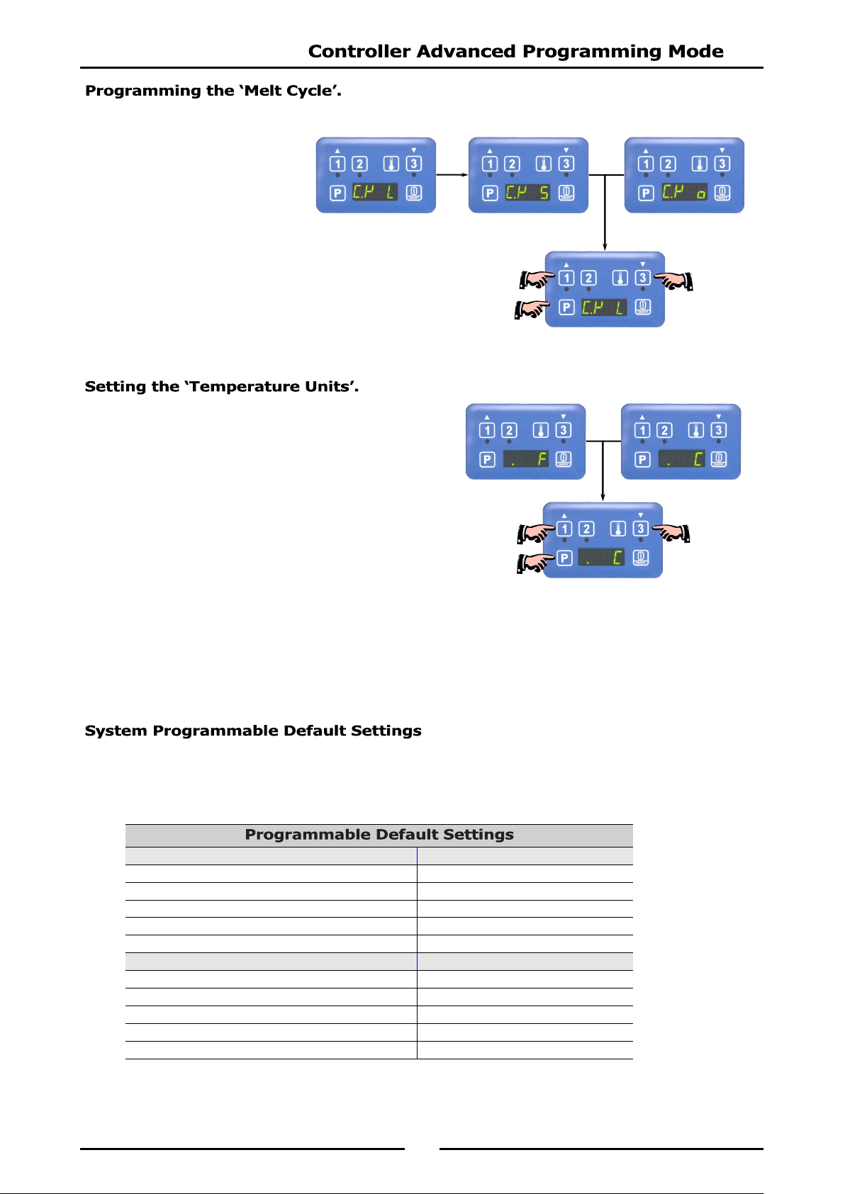
1. One of the following 3 options may be selected:-
‘L’ (Liquid).
‘S’ (Solid).
‘O’ (Override).
2. To change the programmed ‘Melt Cycle’, press either
‘Timer 1’ or ‘Timer 3’ Key to scroll through the three
options.
3. Once the desired option is selected, press Program Key
‘P’ to accept the change, display will step on to ‘Setting
the Temperature Units’.
1. User may select from ‘F’ (Fahrenheit) or ‘C’ (Celsius).
2. Press either ‘Timer 1’ or ‘Timer 3’ Key to change
selection.`
3. Press Programme ‘P’ Key , the change will be
accepted and display will revert to ‘Idle Mode’.
NOTE:
Pressing and holding Programme ‘P’ Key for approximately 3 seconds (Or not pressing
any keys for 2 minutes) during Advanced Programming Mode, the appliance will exit
Advanced Programming Mode and return to Idle Mode.
The table below shows a list of the programmable parameters and the default settings for this appliance.
These settings can be edited from the Control Panel when in either ‘Controller Basic Programme Mode’
or ‘Controller Advanced Programming Mode’.
Controller Basic Programming Mode Default Settings
Timer 1 ‘L’ Cook Time 3:00 min.
Timer 2 'Ctr’ Cook Time 3:00 min.
Timer 3 'R’ Cook Time 3:00 min.
Temperature Set Point 177°C (350°F).
Keypad Lock or Unlock Unlock.
Controller Advanced Programming Mode Default Settings
Timing Mode S.t (Straight).
Temperature Offset 0°.
Temperature Display Mode t. -0 = 'HEAt' or 'droP'.
Melt Cycle Mode L (Liquid).
Degrees; °F or °C °C.
32
When ordering replacement parts, please quote the part number and the description as listed below. If the
part required is not listed below, request the part by description and quote Model and Serial Number which
is shown on the rating plate.
Part No Description FN8127E FN8224E FN8127EE FN8224EE
227962 Neon (Green) 1 2
227963 Neon (Orange) 1 2
227396 Knob 6mm 60-200°C 1 2
228375 Switch Actuator ON/OFF 1 1 1 1
228374 Load Switch ON/OFF 1 1 1 1
024018 Overtemp Thermostat 1 2 1 2
020256 Reset Relay 1 2
011982 Thermostat 1 2
229355 Selector Switch 1 2
024802 Door Microswitch 1 1 1 1
013977 Door Microswitch Insulator 1 1 1 1
014612 Fryer Element (Single Tank 17 kW) 3 3
025929 Fryer Element (Single Tank 21 kW) 3 3
015299 Fryer Element (Double Tank) 6 6
017717 Temperature Probe 1 2
228660 Transformer 24Vac 1 2
020109 Fuse 2 Amp 1 2
229033 Fuse Holder 1 2
228707 Digital Controller 1 2
230101 Controller Overlay (3 basket / timer) 1 2
231739 Contactor 2 4 2 4
025948 Terminal Block - 6 Way 1 2
General
018019 Basket (Standard). 3 3 3 3
227856 Door Magnetic Catch. 1 1 1 1
227451 Door Handle 1 1 1 1
236795 Drain Valve. 1 1
019390 Drain Valve. 2 2
021885 Drain Extension. 1 1
021932 Drain Extension. 1 1
228761 Fryer Lid. 1 1 1 1
015279 Lid Handle (Black) 1 1 1 1
227850 Leg Adjustable - 150mm 2 2 2 2
229674 Rear Roller Assy. 2 2 2 2
IMPORTANT:
33
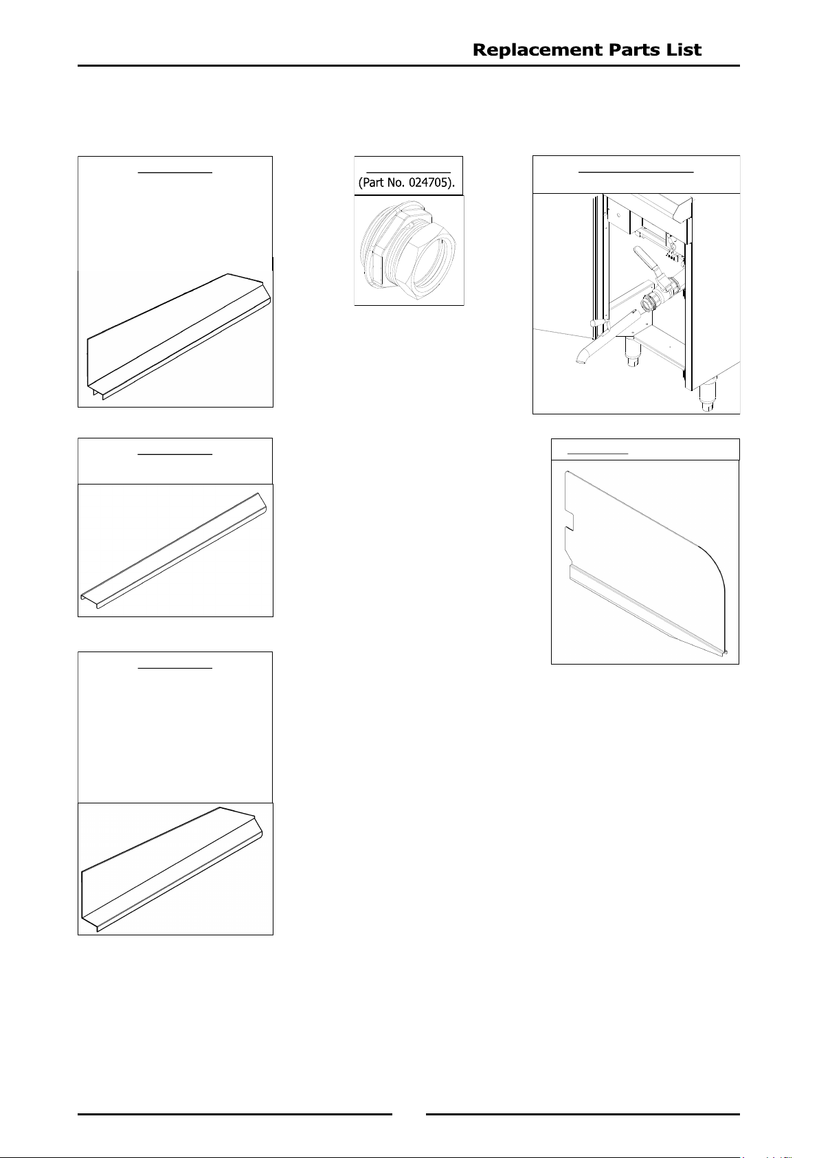
Accessories
228793 Plinth Kit - 450mm (Fryer).
Drain Extension Kit
(Part No. 024710).
Drain Adaptor
Joining Strip
Fryer to Fryer (Part No. 228601).
Splashguard
Fryer;
To Cooktop Griddle.
To Chargrill.
To Griddle.
To Griddle Toaster.
To Cooktop Electric-Griddle
LH (Part No. 228896).
RH (Part No. 228897).
Splashguard
Fryer
To Cooktop Open Burners.
To Target Top.
To Cooktop Electric.
LH (Part No. 228900).
RH (Part No. 228901).
Tank Divider (Part No. 243638).