W4B 4 Burner CO
2
Generator
Summarization
CO
2
generator main uses in plant vegetables,
increase CO
2
content for vegetable and flower planting in
greenhouse. W4B is a safe and economical solution, to
produces CO
2
by burning propane or natural gas or
methane. has some characteristics as follows: high yield,
safety and convenient operation and low cost, it is an
ideal greenhouse product for accelerating plant growth,
increasing yield, improving quality and can enhancing
disease-resistance. This 4 burner CO
2
generator can
produce 3-13 cubic feet per hour. The W4B is
recommended for areas under 3200 cubic feet.
NOTE: An air exchange is recommended when using
CO
2
generators. At least once every hour to avoid your
plants from getting CO
2
poisoning.
The W4B used an automatic electronic ignition module.
When ignite unsuccessfully, the solenoid valve can
automatically prevent the gas from leaking out in the
event. A standard tip over switch is one of the safety
features of the W4B.
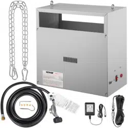
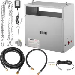
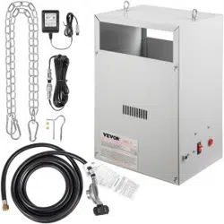
Also, comes standard with 4 brass burners and a 12 foot
hose. A regulator is provided, so that you can connect or
tap into existing lines.
WARNING: Not recommended for use inside of a Grow tent. The high heat can cause melting of the wall
material.
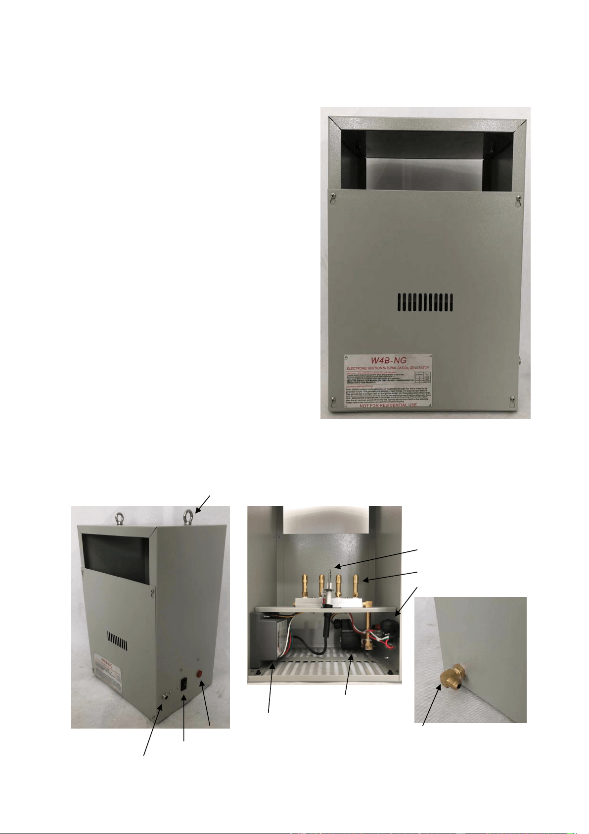
Name of component
Hook
Spark ignitor
& Flame Sensor
Burner
Tip Over Switch
Solenoid Valve
Ignition Module
Power ON Light Gas Connection
Power Switch
Power Connection (24V~AC)

Liquid Propane Gas Regulator In-Line Natural Gas Regulator Power Supply
Installation
1) Determine the desired location for the W4B. It must be mounted at least 18” away from walls or any
flammable material. An 18” clearance must be maintained between the unit and ceiling (18” of chain provided
with W4B). Open flames are present inside the unit, Do not used the unit around flammable materials. Unit
does get warm to the touch.
2) The W4B must be hung correctly for optimum operation. Use the hooks & chains provided with the unit to
secure to ceiling. The unit must be level in order to operate correctly and safe. Tighten all slotted brass caps by
hand, may come loose during shipping.
3) The hose provided is fitted with a standard 3/8” female flare connector. Connect the hose to the back of the
W4B. Use two crescent wrenches or similar to properly tighten the connection. This should be done without
twisting any other connections.
WARNING: Connecting the W4B LP unit to a Natural Gas line, will result in very large flames. Alternatively,
if a W4B-NG is hooked up to propane, this will result in very low and insufficient flames. Make sure your fuel
matches the Generator type.
Propane Generator Only
NOTE: The W4B-LP comes with a standard tank mounted regulator, which should be used unless the
incoming pressure is already regulated to 11” WC (water column).
4) Connect other end of hose to the brass connector on the LP regulator provided. Use the two wrenches again,
one to hold the regulator from the bottom side. The other to twist the 3/8” brass connector on tightly.
5) Open the valve on the propane tank or bigger fuel source. Check the Lines and connections for leaks, by
spraying them with soapy water from a spray bottle. Look for constant bubbling, that would indicate a leak.
Fix leak repeat process.
6) Flip power switch to on position, within 20 sec. unit will begin to spark to ignite the fuel.
Natural Gas Generators Only
NOTE: It is very important to install the regulator “in-Line” between your gas supply and generator. The
regulator supplied with the W4B-NG is present to maintain a constant pressure of 4.5” WC. Which is around ¼
PSI. Before installation, verify your main gas pressure. Most Gas companies install low pressure gas regulators
at the meter that are about ½ PSI. Some commercial buildings have a high pressure gas main (usually around 2
PSI). If the pressure is high, it will need to be reduced to ½ PSI or lower before installing regulator (high
pressure can keep the valves open, causing unit to run with no power).
4) When installing, make sure to install a gas shut-off valve on your line (turn off at main or meter). Install the
shut-off valve in an accessible location. Install the in-line regulator to the gas supply (3/8” NPT female thread).
Connect the hose to the flared fitting on regulator. Using two crescent wrenches or similar to tighten

connections.
5) Open the inline shut off valve (make sure the main is on). Check for leaks using soapy water and a spray
bottle. Look for bubbling, this indicates a leak.
6 ) Flip power switch to on position, within 20 sec. unit will begin to spark to ignite the fuel.
Connecting to CO
2
controller
NOTE: The recommended CO
2
level for optimum growth is between 1000 to 1500 PPM. Above these levels
is considered wasteful. Above 5000 PPM is considered dangerous to animals and humans. Side effects of
excessive CO
2
include headache, drowsiness & shortness of breath. Use a PPM controller to ensure you’re
maintaining proper PPM levels.
1) Connect the CO
2
generator’s power supply to the controller that you are using. Usage of the generator
should be during lights ON hours. At bare minimum, a timer can be used to turn the generator on/off.
Possibilities are likely to exceed recommended PPM range with this method.
2) Set CO
2
controller to desired PPM level and plug in the power of the CO
2
generator into the controller.
Lighting the Generator
1) Connect the power supply to the power connection on the side of the generator and plug it into the wall or
your CO
2
controller.
NOTE: Confirm that the supply voltage and plug voltage is the same.
2) Ensure the power switch on the side of unit is OFF. Turn on the gas supply to the unit.
3) Turn on the power switch. The generator will turn on the valve and attempt to light the generator. It will
make 5 attempts to light the main burner, 20 seconds apart. If the generator does not light the 5th attempt, a red
light will appear on the electric ignition module indicating that it was unable to light in 5th attempts. And give
alarm. It will not try again until the power is cycled. Turn off the power switch and turn it back on, it should
light with the next 5 attempts after all the air in the das line is gone. Depending on the length of the gas hose,
you might need to turn it on and off to 3 or 4 times, if your generator still will not light, please refer to the
troubleshooting tips at the end of this instruction manual.
4) Once the main burner lights, it is should light reliably until the tank (propane only) is changed out.
5) The red indicator light on the side of the generator and blue light on the ignition module is both on as long
as the main burner is running.
Proper Sizing
It is important to consider that some manufactures have inaccuracies within their generator ratings. In order to
compare sizes, a very simple conversion can be used to determine a CO
2
generator’s actual capacity to produce
CO
2
. That is assuming you know the actual Btu output of the unit. British thermal units (BTUs) are stated as
the actual heat output of the unit. Heat output (BTU), is determined simply by knowing the pressure of the gas,
the type of gas (LP or natural) and the volume of gas allowed to flow to the burner.
To convert an LP generator’s Btu rating into cubic feet of CO
2
per hour:
Btu / hr ×1.18
Example: 11,176×1.18 11,176 ×1.18 = 13,187
1000 1000 1000 = 13.2 cuft CO
2
/ hr
To convert an LP generator’s Btu rating into cubic feet of CO
2
per hour:
Btu / hr
Example: 12540
1000 1000 = 12.5 cuft CO
2
/ hr
So a CO
2
generator running propane, with a rating of 11,176 Btu will produce 13.2 cubic feet of CO
2
per hour
assuming a standard pressure of 11” WP is used. A natural gas fired generator rated 12540 will produce up to
12.5 cubic feet per hour. That’s not the only thing to consider.

Reducing Burners
The W4B CO
2
generator installed four burners, you can reduce them as needed, front panel can be removed.
Four screws are used to secure the panel in place. Simply loosen the screws and lift the panel off the keyhole in
order to expose the burner assembly. Be sure to replace the cover prior to operating.
Troubleshooting
If you are having problem with this unit, refer to these troubleshooting hints.
The generator not light
1) There could be air in the gas line, especially when changing propane tanks or turning on your generator for
the first time. Turn generator off and turn it back on. Let it attempt to light 5 times and then repeat.
2) If the generator lights the main burner and then immediately turns back off, the flame sensor may not be
directly in line of the flame. Tighten up the slotted jet caps on both sides of the spark ignitor/flame sensor so
that the flames coming out of the burner are aimed at the spark ignitor/flame sensor. Bend the mounting
bracket slightly to adjust the flame sensor to be in the heat of the flame.
3) Make sure that tank is full and that the gas is turned on.
4) Verify the unit matches the type of gas you are supplying and the gas pressure is correct.
The flame on the main burner seem either too large with yellow flame or too small “flashing” ON and Off
1) You may have mixed burners. Verify you are using natural gas burner with natural gas and propane burner
with propane.
2) Lazy yellow flame indicate low gas flow due to low propane tank level or low natural gas pressure. Long
piping runs with natural gas need to be appropriately size.
3) Verify the unit matches the type of gas you are supplying and the gas pressure is correct.
The unit is plugged in and turned on but the burner don’t work
1) Verify the power switch is ON and the power supply is getting power.
2) make sure the unit is level. If the unit is title more than 35 degrees in any direction, the unit can’t operate.
NOTE: After making the gas connections ALWAYS check for leaks using soapy water and a spray bottle.
This unit is not for residential use. The exterior of the unit can get very HOT when in operation.
Always wait for generator to properly cool down prior to servicing or removing the front panel.
Do not operate the unit with the front panel removed.
When the unit stops using or depositing in the room, should turn off the power and gas source.
When it does not use for a long time, should separate the CO2 generator and gas source.
Warranty:
The W4B is warranted against defects in workmanship and parts for Three years, non-transferable.
Specifications:
Power supply in: 120v~ or 240V~ depending on the power supply
Power supply out: 24 volts AC
Propane Pressure: 11” WC Natural Gas Pressure: 4.5” WC
Total BTU 1 burner: Propane 2,794/ Natural Gas 3,135
Total BTU 2 burner: Propane 5,588/ Natural Gas 6,270
Total BTU 3 burner: Propane 8,382/ Natural Gas 9,405
Total BTU 4 burner: Propane 11,178/ Natural Gas 12,540
Shipping Weight: 12lbs
Dimensions: 11”x16 ½” x 8 1/2”