INSTRUCTION MANUAL
MANUAL DE INSTRUCCIONES
Cordless Circular Saw
Sierra Circular Inalámbrica
GSH03
IMPORTANT: Read Before Using.
IMPORTANTE: Lea antes de usar.
2 ENGLISH
ENGLISH (Original instructions)
SPECIFICATIONS
Model: GSH03
Blade diameter 235 mm (9-1/4")
Max. Cutting depth at 0° 85 mm (3-3/8")
at 45° bevel 61 mm (2-3/8")
at 60° bevel 44 mm (1-3/4")
No load speed 4,000 /min
Overall length 413 mm (16-1/4")
Rated voltage D.C. 36 V - 40 V max
Net weight 5.1 - 5.7 kg (11.2 - 12.6 lbs)
• Duetoourcontinuingprogramofresearchanddevelopment,thespecicationshereinaresubjecttochange
without notice.
• Specicationsandbatterycartridgemaydierfromcountrytocountry.
• Theweightmaydierdependingontheattachment(s),includingthebatterycartridge.Thelightestandheavi-
est combinations, according to EPTA-Procedure 01/2014, are shown in the table.
Applicable battery cartridge and charger
Batterycartridge BL4020 / BL4025 / BL4040 / BL4050F*
*:Recommendedbattery
Charger DC40RA / DC40RB / DC40RC
• Someofthebatterycartridgesandchargerslistedabovemaynotbeavailabledependingonyourregionof
residence.
WARNING: Only use the battery cartridges and chargers listed above.Useofanyotherbatterycartridges
andchargersmaycauseinjuryand/orre.
SAFETY WARNINGS
General power tool safety warnings
WARNING: Read all safety warnings, instruc-
tions, illustrations and specications provided
with this power tool. Failure to follow all instructions
listedbelowmayresultinelectricshock,reand/or
seriousinjury.
Save all warnings and instruc-
tions for future reference.
Theterm"powertool"inthewarningsreferstoyour
mains-operated(corded)powertoolorbattery-operated
(cordless) power tool.
Work area safety
1. Keep work area clean and well lit. Cluttered or
dark areas invite accidents.
2. Do not operate power tools in explosive atmo-
spheres, such as in the presence of ammable
liquids, gases or dust. Power tools create sparks
whichmayignitethedustorfumes.
3. Keep children and bystanders away while
operating a power tool. Distractions can cause
youtolosecontrol.
Electrical Safety
1.
Power tool plugs must match the outlet. Never modify
the plug in any way. Do not use any adapter plugs
with earthed (grounded) power tools. Unmodiedplugs
and matching outlets will reduce risk of electric shock.
2. Avoid body contact with earthed or grounded
surfaces, such as pipes, radiators, ranges and
refrigerators. There is an increased risk of elec-
tricshockifyourbodyisearthedorgrounded.
3. Do not expose power tools to rain or wet con-
ditions. Water entering a power tool will increase
the risk of electric shock.
4.
Do not abuse the cord. Never use the cord for carrying,
pulling or unplugging the power tool. Keep cord away
from heat, oil, sharp edges or moving parts. Damaged
or entangled cords increase the risk of electric shock.
5.
When operating a power tool outdoors, use an
extension cord suitable for outdoor use. Use of a cord
suitable for outdoor use reduces the risk of electric shock.
6.
If operating a power tool in a damp location is unavoid-
able, use a ground fault circuit interrupter (GFCI) protected
supply. Use of a GFCI reduces the risk of electric shock.
7.
Power tools can produce electromagnetic elds
(EMF) that are not harmful to the user. However,
users of pacemakers and other similar medical
devices should contact the maker of their device and/
or doctor for advice before operating this power tool.

3 ENGLISH
Personal Safety
1. Stay alert, watch what you are doing and use
common sense when operating a power tool.
Do not use a power tool while you are tired or
under the inuence of drugs, alcohol or med-
ication. A moment of inattention while operating
powertoolsmayresultinseriouspersonalinjury.
2. Use personal protective equipment. Always
wear eye protection. Protective equipment such
asdustmask,non-skidsafetyshoes,hardhat,or
hearing protection used for appropriate conditions
willreducepersonalinjuries.
3. Prevent unintentional starting. Ensure the
switch is in the o-position before connecting
to power source and/or battery pack, picking
up or carrying the tool.Carryingpowertoolswith
yourngerontheswitchorenergisingpowertools
that have the switch on invites accidents.
4. Remove any adjusting key or wrench before
turning the power tool on.Awrenchorakeyleft
attachedtoarotatingpartofthepowertoolmay
resultinpersonalinjury.
5. Do not overreach. Keep proper footing and
balance at all times. This enables better control
of the power tool in unexpected situations.
6. Dress properly. Do not wear loose clothing or
jewellery. Keep your hair, clothing and gloves
away from moving parts.Looseclothes,jewel-
leryorlonghaircanbecaughtinmovingparts.
7. If devices are provided for the connection of
dust extraction and collection facilities, ensure
these are connected and properly used. Use of
dust collection can reduce dust-related hazards.
8. Do not let familiarity gained from frequent use
of tools allow you to become complacent and
ignore tool safety principles. A careless action
cancausesevereinjurywithinafractionofa
second.
9.
Always wear protective goggles to protect your
eyes from injury when using power tools. The
goggles must comply with ANSI Z87.1 in the USA.
It is an employer's responsibility to enforce the
use of appropriate safety protective equipment
by the tool operators and by other persons in
the immediate working area.
Power tool use and care
1. Do not force the power tool. Use the correct
power tool for your application. The correct
powertoolwilldothejobbetterandsaferatthe
rate for which it was designed.
2. Do not use the power tool if the switch does
not turn it on and o.Anypowertoolthatcannot
be controlled with the switch is dangerous and
must be repaired.
3. Disconnect the plug from the power source
and/or remove the battery pack, if detachable,
from the power tool before making any adjust-
ments, changing accessories, or storing power
tools.Suchpreventivesafetymeasuresreduce
theriskofstartingthepowertoolaccidentally.
4. Store idle power tools out of the reach of chil-
dren and do not allow persons unfamiliar with
the power tool or these instructions to operate
the power tool. Power tools are dangerous in the
hands of untrained users.
5.
Maintain power tools and accessories. Check for
misalignment or binding of moving parts, break-
age of parts and any other condition that may
aect the power tool’s operation. If damaged, have
the power tool repaired before use.Manyaccidents
arecausedbypoorlymaintainedpowertools.
6. Keep cutting tools sharp and clean.Properly
maintained cutting tools with sharp cutting edges
arelesslikelytobindandareeasiertocontrol.
7. Use the power tool, accessories and tool bits
etc. in accordance with these instructions, tak-
ing into account the working conditions and
the work to be performed. Use of the power tool
foroperationsdierentfromthoseintendedcould
result in a hazardous situation.
8.
Keep handles and grasping surfaces dry, clean
and free from oil and grease.Slipperyhandlesand
grasping surfaces do not allow for safe handling and
control of the tool in unexpected situations.
9. When using the tool, do not wear cloth work
gloves which may be entangled. The entangle-
mentofclothworkglovesinthemovingpartsmay
resultinpersonalinjury.
Battery tool use and care
1. Recharge only with the charger specied by
the manufacturer. A charger that is suitable for
onetypeofbatterypackmaycreateariskofre
whenusedwithanotherbatterypack.
2. Use power tools only with specically desig-
nated battery packs.Useofanyotherbattery
packsmaycreateariskofinjuryandre.
3. When battery pack is not in use, keep it away
from other metal objects, like paper clips,
coins, keys, nails, screws or other small metal
objects, that can make a connection from one
terminal to another.Shortingthebatterytermi-
nalstogethermaycauseburnsorare.
4. Under abusive conditions, liquid may be
ejected from the battery; avoid contact. If con-
tact accidentally occurs, ush with water. If
liquid contacts eyes, additionally seek medical
help.Liquidejectedfromthebatterymaycause
irritation or burns.
5. Do not use a battery pack or tool that is dam-
aged or modied.Damagedormodiedbatteries
mayexhibitunpredictablebehaviourresultingin
re,explosionorriskofinjury.
6. Do not expose a battery pack or tool to re or
excessive temperature.Exposuretoreortem-
peratureabove130°Cmaycauseexplosion.
7. Follow all charging instructions and do not
charge the battery pack or tool outside the
temperature range specied in the instruc-
tions.Chargingimproperlyorattemperatures
outsidethespeciedrangemaydamagethe
batteryandincreasetheriskofre.
Service
1. Have your power tool serviced by a qualied
repair person using only identical replacement
parts.Thiswillensurethatthesafetyofthepower
tool is maintained.
2. Never service damaged battery packs. Service
ofbatterypacksshouldonlybeperformedbythe
manufacturer or authorized service providers.
4 ENGLISH
3. Follow instruction for lubricating and chang-
ing accessories.
4. Do not modify or attempt to repair the appli-
ance or the battery pack except as indicated in
the instructions for use and care.
Cordless circular saw safety
warnings
Cutting procedures
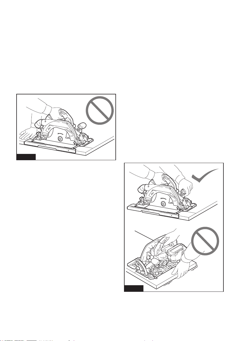
1.
DANGER: Keep hands away from cutting
area and the blade. Keep your second hand
on auxiliary handle, or motor housing. If both
handsareholdingthesaw,theycannotbecutby
the blade.
2. Do not reach underneath the workpiece. The
guardcannotprotectyoufromthebladebelowthe
workpiece.
3. Adjust the cutting depth to the thickness of
the workpiece. Less than a full tooth of the blade
teeth should be visible below the workpiece.
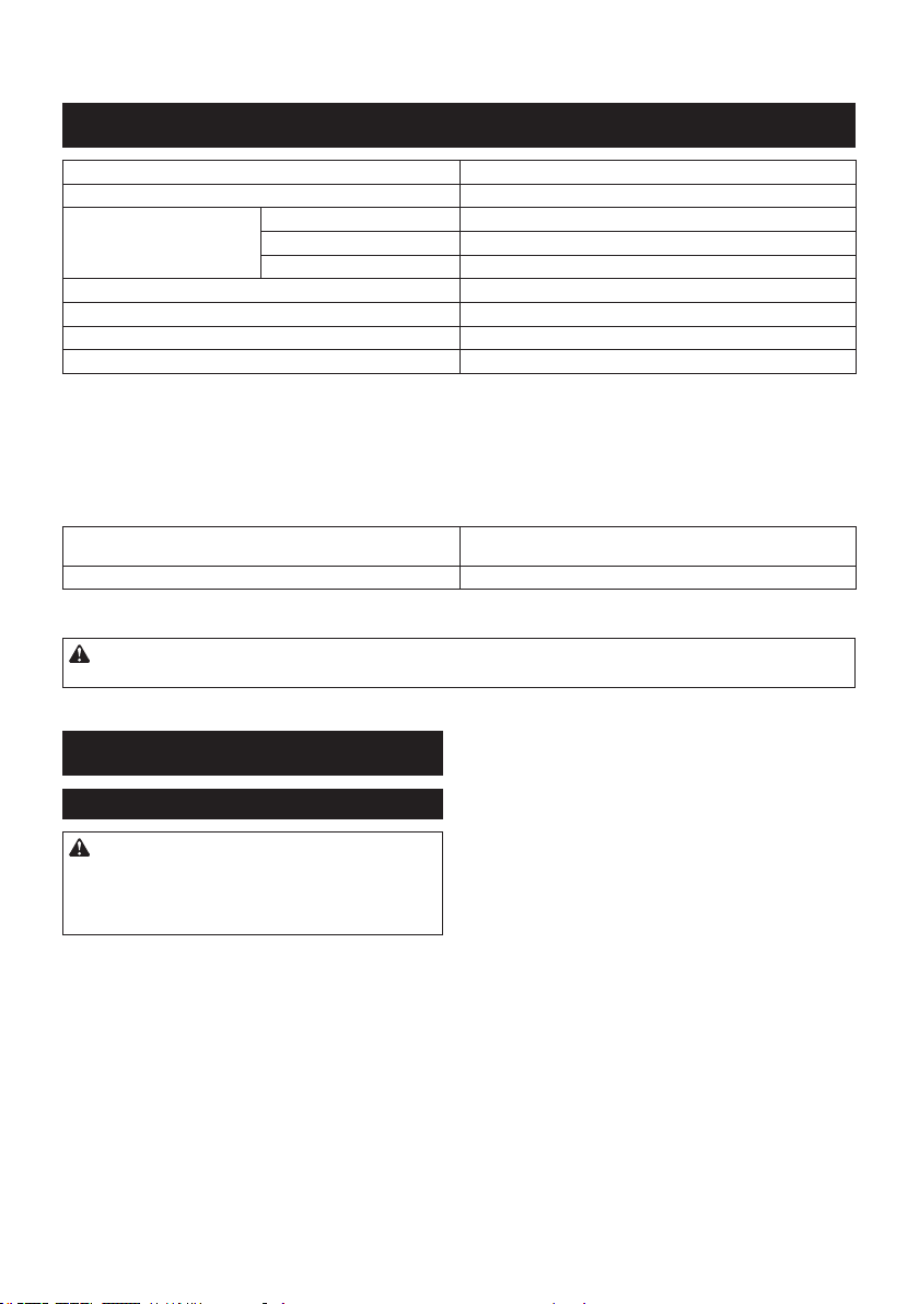
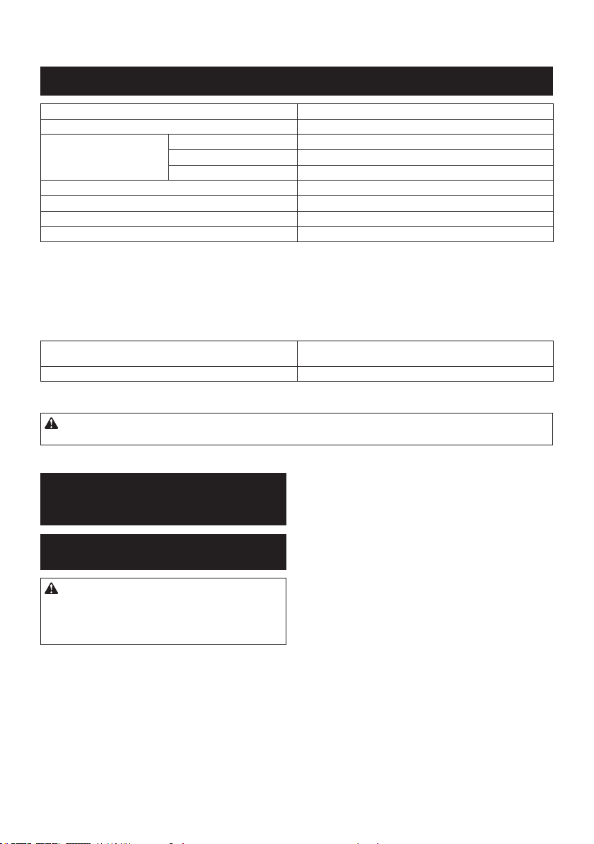
4. Never hold the workpiece in your hands or
across your leg while cutting. Secure the
workpiece to a stable platform. It is important to
supporttheworkproperlytominimisebodyexpo-
sure, blade binding, or loss of control.
Fig.1
5. Hold the power tool by insulated gripping
surfaces, when performing an operation where
the cutting tool may contact hidden wiring.
Contact with a "live" wire will also make exposed
metal parts of the power tool "live" and could give
the operator an electric shock.
6. When ripping, always use a rip fence or
straight edge guide.Thisimprovestheaccuracy
of cut and reduces the chance of blade binding.
7. Always use blades with correct size and shape
(diamond versus round) of arbour holes.
Blades that do not match the mounting hardware
ofthesawwillruno-centre,causinglossof
control.
8. Never use damaged or incorrect blade wash-
ers or bolt. The blade washers and bolt were
speciallydesignedforyoursaw,foroptimum
performanceandsafetyofoperation.
Kickback causes and related warnings
— kickback is a sudden reaction to a pinched,
jammedormisalignedsawblade,causingan
uncontrolled saw to lift up and out of the workpiece
toward the operator;
— whenthebladeispinchedorjammedtightlybythe
kerf closing down, the blade stalls and the motor
reactiondrivestheunitrapidlybacktowardthe
operator;
— if the blade becomes twisted or misaligned in the
cut, the teeth at the back edge of the blade can dig
into the top surface of the wood causing the blade
toclimboutofthekerfandjumpbacktowardthe
operator.
Kickback is the result of saw misuse and/or incorrect
operating procedures or conditions and can be avoided
bytakingproperprecautionsasgivenbelow.
1. Maintain a rm grip with both hands on the
saw and position your arms to resist kickback
forces. Position your body to either side of the
blade, but not in line with the blade. Kickback
couldcausethesawtojumpbackwards,but
kickbackforcescanbecontrolledbytheoperator,
if proper precautions are taken.
2.
When blade is binding, or when interrupting a
cut for any reason, release the trigger and hold
the saw motionless in the material until the
blade comes to a complete stop. Never attempt
to remove the saw from the work or pull the saw
backward while the blade is in motion or kick-
back may occur. Investigate and take corrective
actions to eliminate the cause of blade binding.
3. When restarting a saw in the workpiece, centre
the saw blade in the kerf so that the saw teeth
are not engaged into the material. If a saw blade
binds,itmaywalkuporkickbackfromthework-
piece as the saw is restarted.
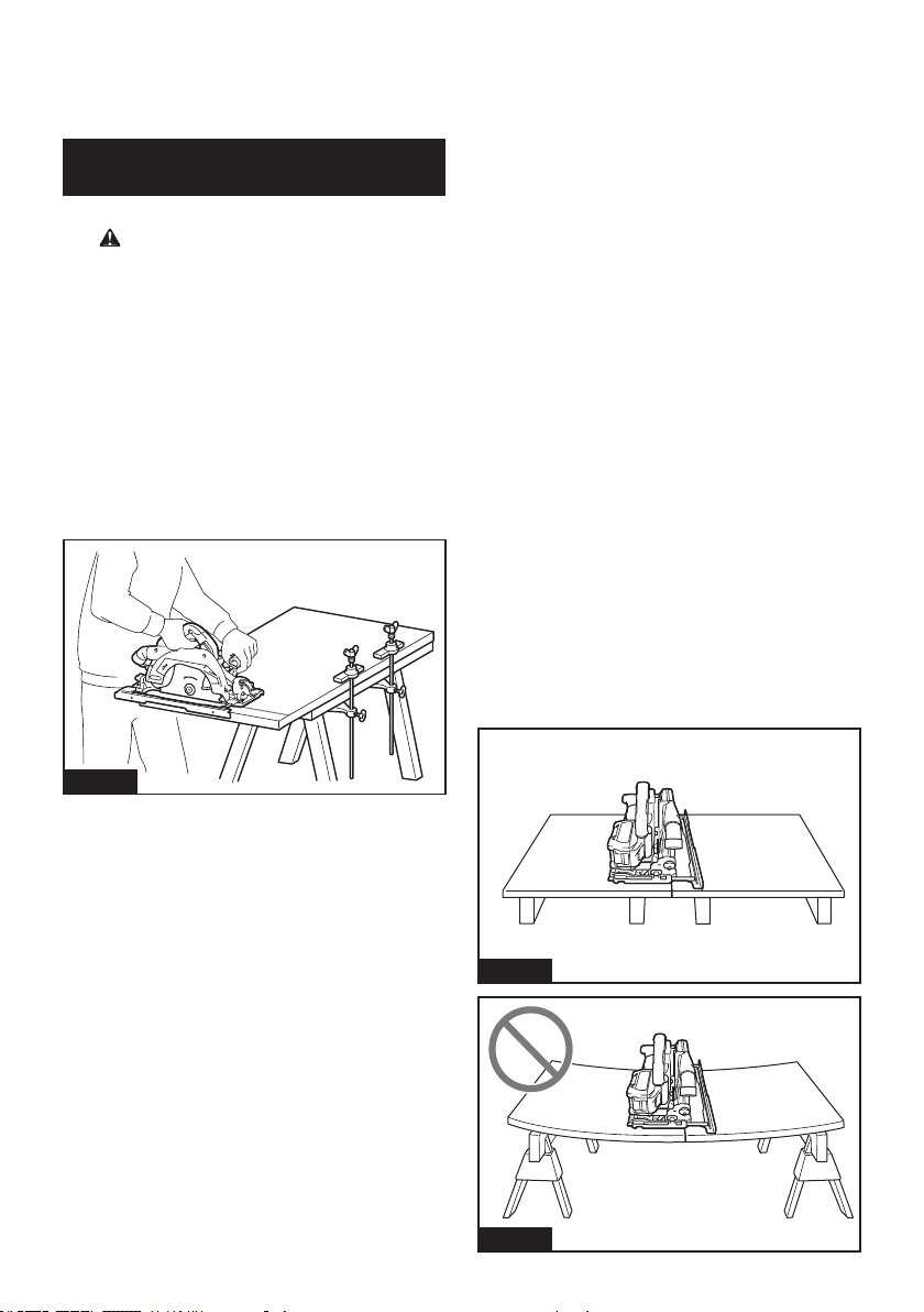
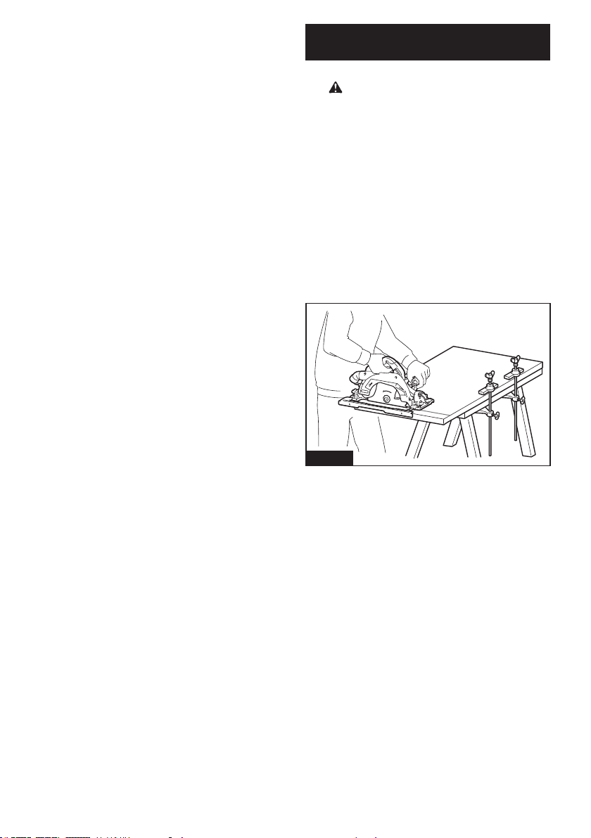
4. Support large panels to minimise the risk of
blade pinching and kickback. Large panels tend
to sag under their own weight. Supports must be
placed under the panel on both sides, near the line
of cut and near the edge of the panel.
Fig.2
Fig.3
5 ENGLISH
5. Do not use dull or damaged blades.
Unsharpenedorimproperlysetbladesproduce
narrow kerf causing excessive friction, blade
binding and kickback.
6. Blade depth and bevel adjusting locking levers
must be tight and secure before making the
cut.Ifbladeadjustmentshiftswhilecutting,itmay
cause binding and kickback.
7. Use extra caution when sawing into existing
walls or other blind areas. The protruding blade
maycutobjectsthatcancausekickback.
8. ALWAYS hold the tool rmly with both hands.
NEVER place your hand, leg or any part of your
body under the tool base or behind the saw,
especially when making cross-cuts. If kickback
occurs,thesawcouldeasilyjumpbackwardsover
yourhand,leadingtoseriouspersonalinjury.
Fig.4
9. Never force the saw. Push the saw forward at a
speed so that the blade cuts without slowing.
Forcing the saw can cause uneven cuts, loss of
accuracy,andpossiblekickback.
Lower guard function
1. Check the lower guard for proper closing
before each use. Do not operate the saw if the
lower guard does not move freely and close
instantly. Never clamp or tie the lower guard
into the open position.Ifthesawisaccidentally
dropped,thelowerguardmaybebent.Raisethe
lower guard with the retracting handle and make
sureitmovesfreelyanddoesnottouchtheblade
oranyotherpart,inallanglesanddepthsofcut.
2. Check the operation of the lower guard spring.
If the guard and the spring are not operating
properly, they must be serviced before use.
Lowerguardmayoperatesluggishlydueto
damagedparts,gummydeposits,orabuild-upof
debris.
3. The lower guard may be retracted manually
only for special cuts such as “plunge cuts”
and “compound cuts”. Raise the lower guard
by the retracting handle and as soon as the
blade enters the material, the lower guard
must be released. For all other sawing, the lower
guardshouldoperateautomatically.
4. Always observe that the lower guard is cover-
ing the blade before placing the saw down on
bench or oor. An unprotected, coasting blade
will cause the saw to walk backwards, cutting
whatever is in its path. Be aware of the time it
takes for the blade to stop after switch is released.
5. To check lower guard, open lower guard by
hand, then release and watch guard closure.
Also check to see that retracting handle does
not touch tool housing. Leaving blade exposed
is VERY DANGEROUS and can lead to serious
personalinjury.
Additional safety warnings
1. Intended use
This tool is intended to cut wood products by
lengthways and crossways straight cuts and
miter cuts with angles while in rm contact
with the workpiece.
Accumulated sawdust on the lower guard and hub
fromothermaterialsmayeecttheproperclosure
of the lower guard which could lead to serious
personalinjury.
2.
Use extra caution when cutting damp wood, pres-
sure treated lumber, or wood containing knots.
Maintain smooth advancement of tool without decrease
in blade speed to avoid overheating the blade tips.
3. Do not attempt to remove cut material when
blade is moving. Wait until blade stops before
grasping cut material.Bladescoastafterturno.
4. Avoid cutting nails. Inspect for and remove all
nails from lumber before cutting.
5. Place the wider portion of the saw base on
that part of the workpiece which is solidly
supported, not on the section that will fall o
when the cut is made. If the workpiece is short
or small, clamp it down. DO NOT TRY TO HOLD
SHORT PIECES BY HAND!
Fig.5
6. Before setting the tool down after completing a
cut, be sure that the guard has closed and the
blade has come to a complete stop.
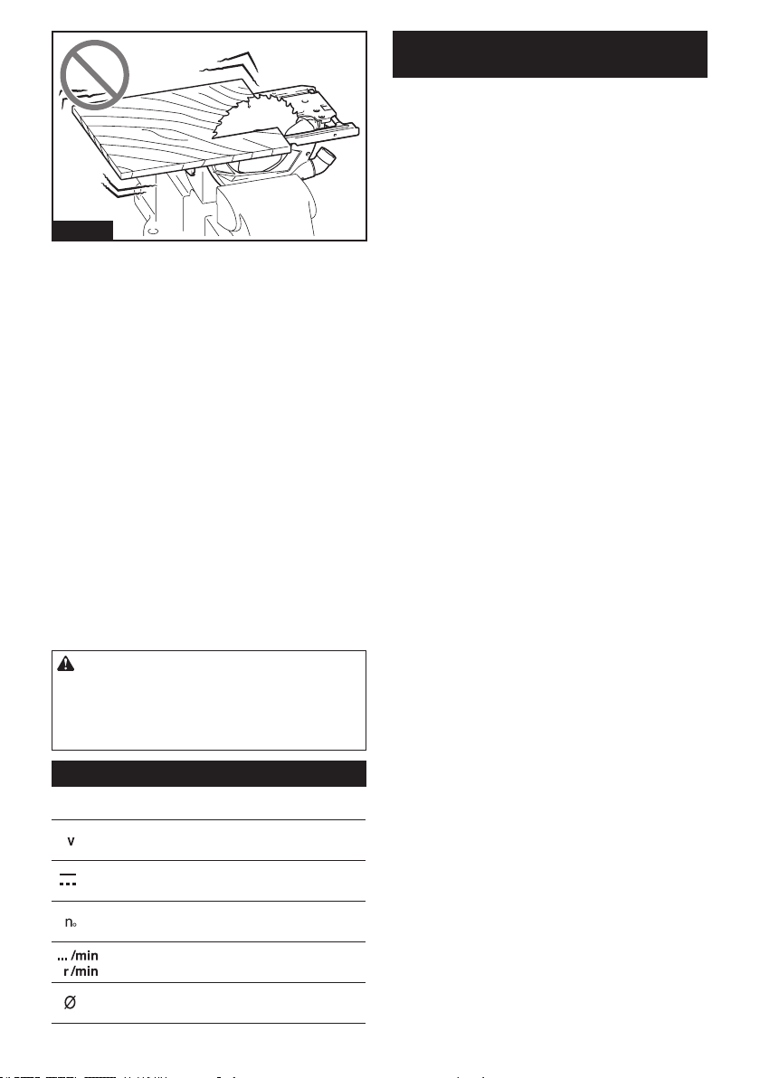
7. Never attempt to saw with the circular saw
held upside down in a vise. This is extremely
dangerous and can lead to serious accidents.
6 ENGLISH
Fig.6
8.
Some material contains chemicals which may be
toxic. Take caution to prevent dust inhalation and
skin contact. Follow material supplier safety data.
9. Do not stop the blades by lateral pressure on
the saw blade.
10. Do not use any abrasive wheels.
11. Only use the saw blade with the diameter that
is marked on the tool or specied in the man-
ual.Useofanincorrectlysizedblademayaect
the proper guarding of the blade or guard opera-
tionwhichcouldresultinseriouspersonalinjury.
12.
Keep blade sharp and clean. Gum and wood pitch
hardened on blades slows saw and increases poten-
tialforkickback.Keepbladecleanbyrstremoving
it from tool, then cleaning it with gum and pitch
remover, hot water or kerosene. Never use gasoline.
13. Wear a dust mask and hearing protection when
use the tool.
14. Always use the saw blade intended for cutting
the material that you are going to cut.
15.
Only use the saw blades that are marked with a speed
equal or higher than the speed marked on the tool.
16.
Place the tool and the parts on a at and stable surface.
Otherwisethetoolorthepartsmayfallandcauseaninjury.
SAVE THESE INSTRUCTIONS.
WARNING: DO NOT let comfort or familiarity
with product (gained from repeated use) replace
strict adherence to safety rules for the subject
product. MISUSE or failure to follow the safety
rules stated in this instruction manual may cause
serious personal injury.
Symbols
Thefollowingsshowthesymbolsusedfortool.
volts
direct current
no load speed
revolutions or reciprocation per minute
diameter
Important safety instructions for
battery cartridge
1. Before using battery cartridge, read all instruc-
tions and cautionary markings on (1) battery
charger, (2) battery, and (3) product using
battery.
2. Do not disassemble or tamper the battery
cartridge.Itmayresultinare,excessiveheat,
or explosion.
3. If operating time has become excessively
shorter, stop operating immediately. It may
result in a risk of overheating, possible burns
and even an explosion.
4. If electrolyte gets into your eyes, rinse them
out with clear water and seek medical atten-
tion right away. It may result in loss of your
eyesight.
5. Do not short the battery cartridge:
(1) Do not touch the terminals with any con-
ductive material.
(2) Avoid storing battery cartridge in a con-
tainer with other metal objects such as
nails, coins, etc.
(3) Do not expose battery cartridge to water
or rain.
A battery short can cause a large current
ow, overheating, possible burns and even a
breakdown.
6. Do not store and use the tool and battery car-
tridge in locations where the temperature may
reach or exceed 50 °C (122 °F).
7. Do not incinerate the battery cartridge even if
it is severely damaged or is completely worn
out. The battery cartridge can explode in a re.
8. Do not nail, cut, crush, throw, drop the battery
cartridge, or hit against a hard object to the
battery cartridge.Suchconductmayresultina
re,excessiveheat,orexplosion.
9. Do not use a damaged battery.
10. The contained lithium-ion batteries are subject
to the Dangerous Goods Legislation require-
ments.
Forcommercialtransportse.g.bythirdparties,
forwarding agents, special requirement on pack-
aging and labeling must be observed.
For preparation of the item being shipped, consult-
ing an expert for hazardous material is required.
Pleasealsoobservepossiblymoredetailed
national regulations.
Tapeormaskoopencontactsandpackupthe
batteryinsuchamannerthatitcannotmove
around in the packaging.
11. When disposing the battery cartridge, remove
it from the tool and dispose of it in a safe
place. Follow your local regulations relating to
disposal of battery.
12. Use the batteries only with the products
specied by Makita. Installing the batteries to
non-compliantproductsmayresultinare,exces-
siveheat,explosion,orleakofelectrolyte.
13. If the tool is not used for a long period of time,
the battery must be removed from the tool.

7 ENGLISH
14. During and after use, the battery cartridge may
take on heat which can cause burns or low
temperature burns. Pay attention to the han-
dling of hot battery cartridges.
15. Do not touch the terminal of the tool imme-
diately after use as it may get hot enough to
cause burns.
16. Do not allow chips, dust, or soil stuck into the
terminals, holes, and grooves of the battery
cartridge.Itmaycauseheating,catchingre,
burstandmalfunctionofthetoolorbatterycar-
tridge,resultinginburnsorpersonalinjury.
17. Unless the tool supports the use near
high-voltage electrical power lines, do not use
the battery cartridge near a high-voltage elec-
trical power lines.Itmayresultinamalfunction
orbreakdownofthetoolorbatterycartridge.
18. Keep the battery away from children.
SAVE THESE INSTRUCTIONS.
CAUTION: Only use genuine Makita batteries.
Use of non-genuine Makita batteries, or batteries that
havebeenaltered,mayresultinthebatterybursting
causingres,personalinjuryanddamage.Itwill
alsovoidtheMakitawarrantyfortheMakitatooland
charger.
Tips for maintaining maximum
battery life
1. Charge the battery cartridge before completely
discharged. Always stop tool operation and
charge the battery cartridge when you notice
less tool power.
2. Never recharge a fully charged battery car-
tridge. Overcharging shortens the battery
service life.
3. Charge the battery cartridge with room tem-
perature at 10 °C - 40 °C (50 °F - 104 °F). Let
a hot battery cartridge cool down before
charging it.
4. When not using the battery cartridge, remove
it from the tool or the charger.
5. Charge the battery cartridge if you do not use
it for a long period (more than six months).
Important safety instructions for
wireless unit
1. Do not disassemble or tamper with the wire-
less unit.
2. Keep the wireless unit away from young chil-
dren. If accidentally swallowed, seek medical
attention immediately.
3. Use the wireless unit only with Makita tools.
4. Do not expose the wireless unit to rain or wet
conditions.
5. Do not use the wireless unit in places where
the temperature exceeds 50 °C (122 °F).
6. Do not operate the wireless unit in places
where medical instruments, such as heart
pace makers are nearby.
7. Do not operate the wireless unit in places
where automated devices are nearby. If oper-
ated,automateddevicesmaydevelopmalfunction
or error.
8. Do not operate the wireless unit in places
under high temperature or places where
static electricity or electrical noise could be
generated.
9. The wireless unit can produce electromagnetic
elds (EMF) but they are not harmful to the
user.
10. The wireless unit is an accurate instrument. Be
careful not to drop or strike the wireless unit.
11. Avoid touching the terminal of the wireless
unit with bare hands or metallic materials.
12. Always remove the battery on the product
when installing the wireless unit into it.
13. When opening the lid of the slot, avoid the
place where dust and water may come into the
slot. Always keep the inlet of the slot clean.
14. Always insert the wireless unit in the correct
direction.
15. Do not press the wireless activation button
on the wireless unit too hard and/or press the
button with an object with a sharp edge.
16. Always close the lid of the slot when
operating.
17. Do not remove the wireless unit from the slot
while the power is being supplied to the tool.
Doingsomaycauseamalfunctionofthewireless
unit.
18. Do not remove the sticker on the wireless unit.
19. Do not put any sticker on the wireless unit.
20. Do not leave the wireless unit in a place where
static electricity or electrical noise could be
generated.
21. Do not leave the wireless unit in a place sub-
ject to high heat, such as a car sitting in the
sun.
22. Do not leave the wireless unit in a dusty or
powdery place or in a place corrosive gas
could be generated.
23. Sudden change of the temperature may bedew
the wireless unit. Do not use the wireless unit
until the dew is completely dried.
24. When cleaning the wireless unit, gently wipe
with a dry soft cloth. Do not use benzine, thin-
ner, conductive grease or the like.
25. When storing the wireless unit, keep it in the
supplied case or a static-free container.
26. Do not insert any devices other than Makita
wireless unit into the slot on the tool.
27. Do not use the tool with the lid of the slot dam-
aged.Water,dust,anddirtcomeintotheslotmay
cause malfunction.
28. Do not pull and/or twist the lid of the slot more
than necessary.Restorethelidifitcomeso
from the tool.
29. Replace the lid of the slot if it is lost or
damaged.
SAVE THESE INSTRUCTIONS.
8 ENGLISH
FUNCTIONAL
DESCRIPTION
CAUTION: Always be sure that the tool is
switched o and the battery cartridge is removed
before adjusting or checking function on the tool.
Installing or removing battery
cartridge
CAUTION: Always switch o the tool before
installing or removing of the battery cartridge.
CAUTION: Hold the tool and the battery car-
tridge rmly when installing or removing battery
cartridge.Failuretoholdthetoolandthebattery
cartridgermlymaycausethemtoslipoyourhands
andresultindamagetothetoolandbatterycartridge
andapersonalinjury.
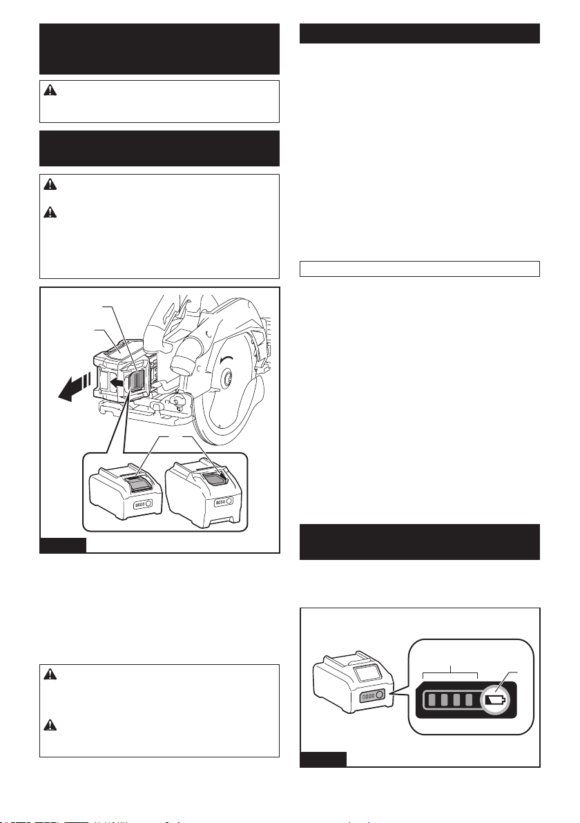
3
2
1
Fig.7
►1. Red indicator 2. Button 3.Batterycartridge
Toremovethebatterycartridge,slideitfromthetool
while sliding the button on the front of the cartridge.
Toinstallthebatterycartridge,alignthetongueonthe
batterycartridgewiththegrooveinthehousingandslip
itintoplace.Insertitallthewayuntilitlocksinplace
withalittleclick.Ifyoucanseetheredindicatoras
showninthegure,itisnotlockedcompletely.
CAUTION: Always install the battery cartridge
fully until the red indicator cannot be seen. If not,
itmayaccidentallyfalloutofthetool,causinginjuryto
youorsomeonearoundyou.
CAUTION: Do not install the battery cartridge
forcibly.Ifthecartridgedoesnotslideineasily,itis
notbeinginsertedcorrectly.
Tool / battery protection system
Thetoolisequippedwithatool/batteryprotectionsys-
tem.Thissystemautomaticallycutsopowertothe
motortoextendtoolandbatterylife.Thetoolwillauto-
maticallystopduringoperationifthetoolorbatteryis
placed under one of the following conditions.
Overload protection
Whenthetool/batteryisoperatedinamannerthat
causesittodrawanabnormallyhighcurrent,thetool
automaticallystops.Inthissituation,turnthetoolo
and stop the application that caused the tool to become
overloaded. Then turn the tool on to restart.
Overheat protection
Whenthetool/batteryisoverheated,thetoolstops
automatically.Inthissituation,letthetoolcooldown
before turning the tool on again.
NOTE: When the tool is overheated, the lamp blinks.
Overdischarge protection
Whenthebatterycapacitybecomeslow,thetoolstops
automatically.Iftheproductdoesnotoperateeven
when the switches are operated, remove the batteries
from the tool and charge the batteries.
Protections against other causes
Protectionsystemisalsodesignedforothercauses
that could damage the tool and allows the tool to stop
automatically.Takeallthefollowingstepstoclearthe
causes,whenthetoolhasbeenbroughttoatemporary
halt or stop in operation.
1.
Turnthetoolo,andthenturnitonagaintorestart.
2. Chargethebattery(ies)orreplaceit/themwith
rechargedbattery(ies).
3. Letthetoolandbattery(ies)cooldown.
Ifnoimprovementcanbefoundbyrestoringprotection
system,thencontactyourlocalMakitaServiceCenter.
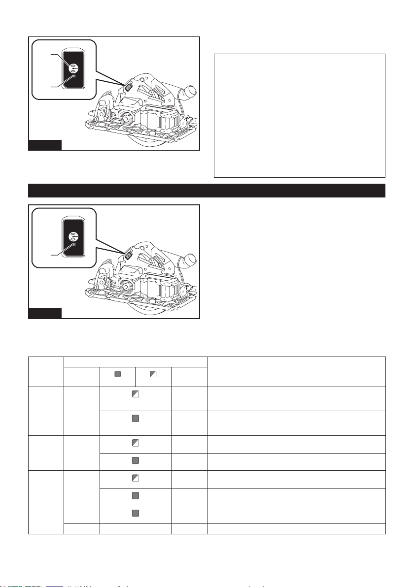
Indicating the remaining battery
capacity
Pressthecheckbuttononthebatterycartridgetoindi-
catetheremainingbatterycapacity.Theindicatorlamps
light up for a few seconds.
1
2
Fig.8
►1. Indicator lamps 2. Check button
9 ENGLISH
Indicator lamps Remaining
capacity
Lighted O Blinking
75% to 100%
50% to 75%
25% to 50%
0% to 25%
Charge the
battery.
Thebattery
mayhave
malfunctioned.
NOTE: Depending on the conditions of use and the
ambienttemperature,theindicationmaydierslightly
fromtheactualcapacity.
NOTE:Therst(farleft)indicatorlampwillblinkwhen
thebatteryprotectionsystemworks.
Switch action
WARNING: Before installing the battery car-
tridge into the tool, always check to see that the
switch trigger actuates properly and returns to
the "OFF" position when released.
WARNING: NEVER defeat the lock-o button
by taping down or some other means. A switch with
anegatedlock-obuttonmayresultinunintentional
operationandseriouspersonalinjury.
WARNING: NEVER use the tool if it runs when
you simply pull the switch trigger without press-
ing the lock-o button. A switch in need of repair
mayresultinunintentionaloperationandserious
personalinjury.ReturntooltoaMakitaservicecenter
for proper repairs BEFORE further usage.
Topreventtheswitchtriggerfrombeingaccidentally
pulled,alock-obuttonisprovided.Tostartthetool,
depressthelock-obuttonandpulltheswitchtrigger.
Release the switch trigger to stop.
2
1
Fig.9
►1. Switch trigger 2.Lock-obutton
NOTICE: Do not pull the switch trigger hard
without pressing in the lock-o button. This can
cause switch breakage.
CAUTION:
The tool starts to brake the circular saw
blade rotation immediately after you release the switch
trigger. Hold the tool rmly to respond the reaction of the
brake when releasing the switch trigger. Sudden reaction
candropthetooloyourhandandcancauseapersonalinjury.
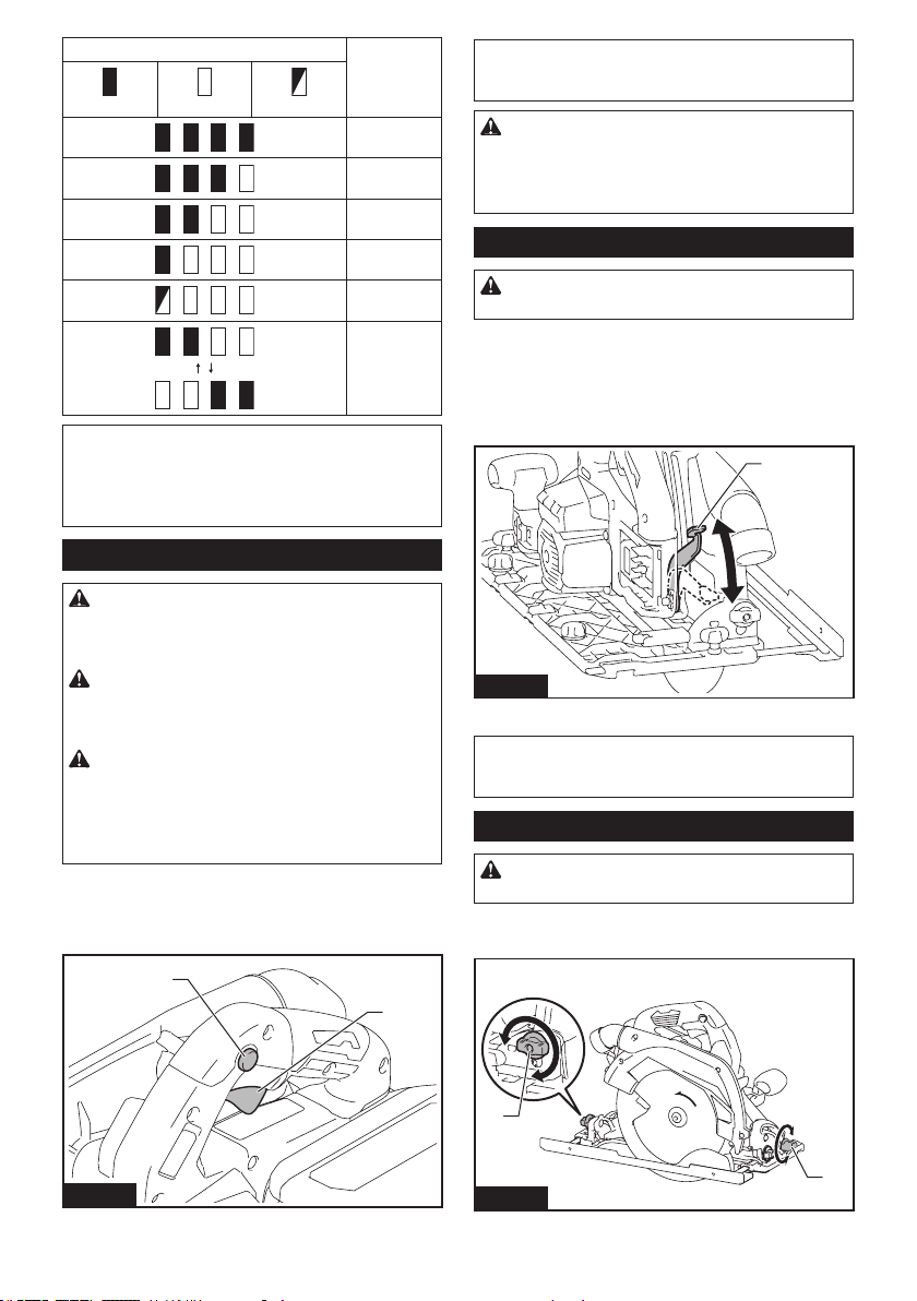
Adjusting depth of cut
CAUTION: After adjusting the depth of cut,
always tighten the lever securely.
Loosen the lever on the depth guide and move the base up or down.
Atthedesireddepthofcut,securethebasebytighteningthelever.
For cleaner, safer cuts, set cut depth so that no more
thanonebladetoothprojectsbelowworkpiece.Using
proper cut depth helps to reduce potential for danger-
ousKICKBACKSwhichcancausepersonalinjury.
1
Fig.10
►1. Lever
NOTICE:
Ifthebasedoesn'tslideupordownsmoothly,the
depthguidemayhavebeentilted.Inthiscase,adjustthedepth
guide(referthesectionaboutadjustingthedepthguide).
Bevel cutting
CAUTION: After adjusting the bevel angle,
always tighten the clamping screws securely.
Loosentheclampingscrews.Setforthedesiredangleby
tiltingaccordingly,thentightentheclampingscrewssecurely.
1
1
Fig.11
►1. Clamping screw
10 ENGLISH
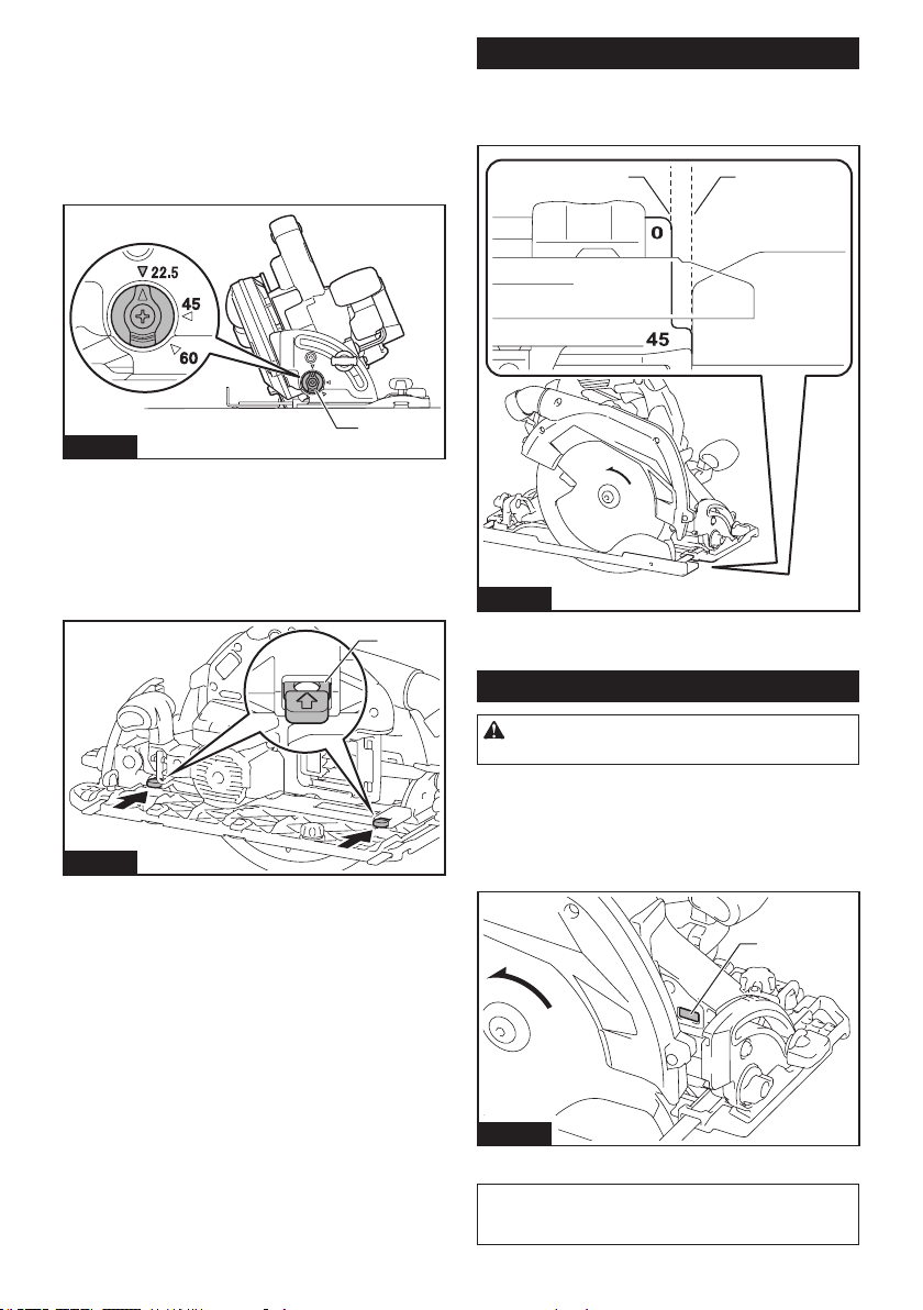
Positive stopper
The positive stopper is useful for setting the designated
anglequickly.Turnthepositivestoppersothatthe
arrowonitpointsyourdesiredbevelangle(around
22.5°/45°/60°). Loosen the lever and then tilt the tool
base until it stops. The position where the tool base
stopsistheangleyousetwiththepositivestopper.
Tighten the lever with the tool base at this position.
1
Fig.12
►1. Positive stopper
-1°-bevel cutting
To perform -1°-bevel cutting, loosen the clamping
screws and press the levers toward the direction of the
arrowinthegure.Thensetthebevelangleto-1°and
tighten the clamping screws.
1
Fig.13
►1. Lever
Sighting
For straight cuts, align the 0° position on the front of the
basewithyourcuttingline.For45°bevelcuts,alignthe
45° position with it.
1 2
Fig.14
►1. Cutting line (0° position) 2. Cutting line (45°
position)
Lighting the lamp
CAUTION: Do not look in the light or see the
source of light directly.
To turn on the lamp without running the tool, pull the
switchtriggerwithoutpressingthelock-obutton.
To turn on the lamp with the tool running, press and hold
thelock-obuttonandpulltheswitchtrigger.
The lamp goes out 10 seconds after releasing the
switch trigger.
1
Fig.15
►1. Lamp
NOTE:Useadryclothtowipethedirtothelensof
the lamp. Be careful not to scratch the lens of lamp, or
itmaylowertheillumination.
11 ENGLISH
Electric brake
This tool is equipped with an electric blade brake. If the
toolconsistentlyfailstoquicklystopthecircularsaw
blade after switch lever release, have tool serviced at a
Makita service center.
CAUTION: The blade brake system is not a
substitute for blade guard. NEVER USE TOOL
WITHOUT A FUNCTIONING BLADE GUARD.
SERIOUS PERSONAL INJURY CAN RESULT.
Electronic function
Thetoolsequippedwithelectronicfunctionareeasyto
operate because of the following feature(s).
Soft start feature
Soft start because of suppressed starting shock.
Constant speed control
Electronic speed control for obtaining constant speed.
Possibletogetnenish,becausetherotatingspeedis
kept constant even under load condition.
ASSEMBLY
CAUTION: Always be sure that the tool is
switched o and the battery cartridge is removed
before carrying out any work on the tool.
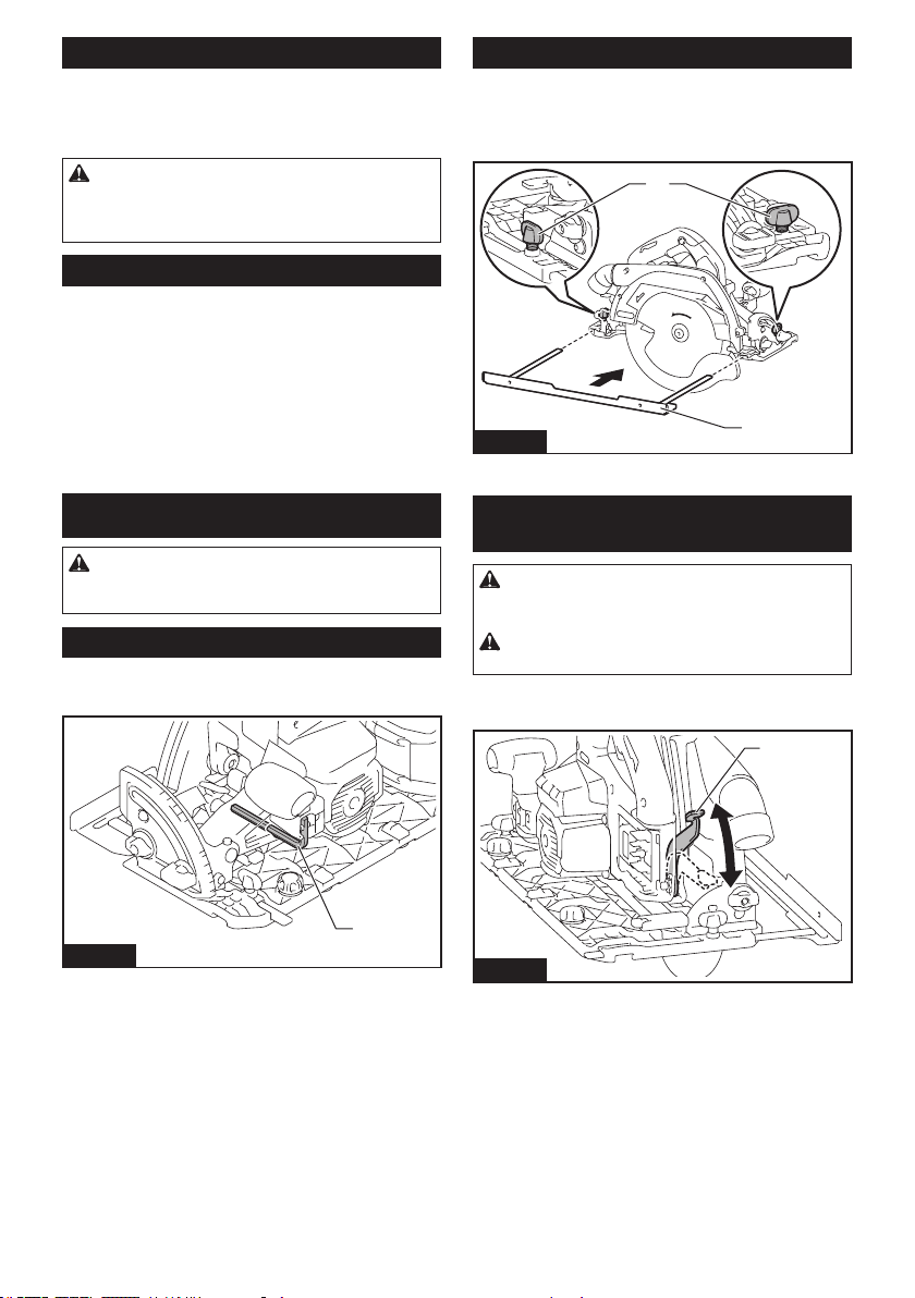
Hex wrench storage
When not in use, store the hex wrench as shown in the
guretokeepitfrombeinglost.
1
Fig.16
►1. Hex wrench
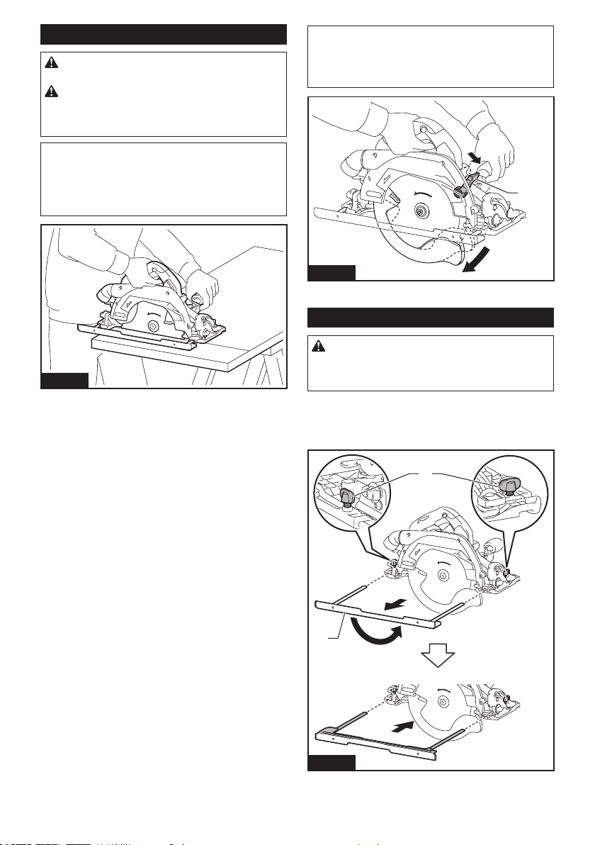
Installing sub base
Install the sub base and tighten the clamping screws
securelyasshowninthegure.
Alwaysusethetoolwiththesubbaseunlesswhen
using the guide rail.
1
2
Fig.17
►1. Clamping screw 2. Sub base
Installing or removing circular saw
blade
CAUTION: Be sure the circular saw blade is
installed with teeth pointing up at the front of the
tool.
CAUTION: Use only the Makita wrench to
install or remove the circular saw blade.
1. Loosen the lever on the depth guide and move the
base down.
1
Fig.18
►1. Lever
12 ENGLISH
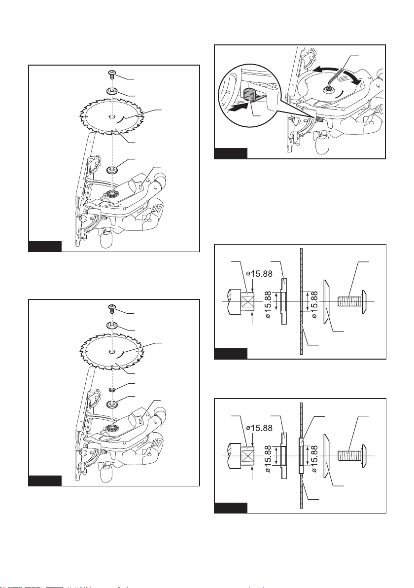
2. Installtheinnerange,ring(countryspecic),
circularsawblade,outerangeandhexbolt.Atthis
time, align the direction of the arrow on the blade with
the arrow on the tool.
For tool without the ring
1
2
4
5
6
3
Fig.19
►1. Hex bolt 2.Outerange3. Circular saw blade
4.Innerange5. Arrow on the circular saw blade
6. Arrow on the tool
For tool with the ring
1
2
4
5
3
6
7
Fig.20
►1. Hex bolt 2.Outerange3. Circular saw blade
4. Ring 5.Innerange6. Arrow on the circular saw
blade 7. Arrow on the tool
3. Presstheshaftlockfullysothatthecircularsaw
blade cannot revolve and use the hex wrench to tighten
the hex bolt.
1
2
3
4
Fig.21
►1. Shaft lock 2. Hex wrench 3. Loosen 4. Tighten
To remove the circular saw blade, follow the installation
procedure in reverse.
Mounttheinnerangewithitsrecessedsidefacing
outward onto the mounting shaft and then place circu-
lar saw blade (with the ring attached if needed), outer
angeandhexbolt.
For tool without the ring
12
3
4
5
Fig.22
►1. Mounting shaft 2.Innerange3. Circular saw
blade 4.Outerange5. Hex bolt
For tool with the ring
12
3
4
5
6
Fig.23
►1. Mounting shaft 2.Innerange3. Circular saw
blade 4.Outerange5. Hex bolt 6. Ring
13 ENGLISH
WARNING: BE SURE TO TIGHTEN THE HEX
BOLT CLOCKWISE SECURELY. Also be careful
not to tighten the bolt forcibly. Slipping your hand
from the hex wrench can cause a personal injury.
WARNING: If the ring is needed to mount the
blade onto the spindle, always be sure that the
correct ring for the blade's arbor hole you intend
to use is installed between the inner and the outer
anges.Useoftheincorrectarborholeringmay
result in the improper mounting of the blade causing
blade movement and severe vibration resulting in
possible loss of control during operation and in seri-
ouspersonalinjury.
Blade guard cleaning
When changing the circular saw blade, make sure to
also clean the upper and lower blade guards of accu-
mulated sawdust as discussed in the Maintenance
section.Sucheortsdonotreplacetheneedtocheck
lower guard operation before each use.
Connecting a vacuum cleaner
Optional accessory
Whenyouwishtoperformcleancuttingoperation,
connectaMakitavacuumcleanertoyourtool.Connect
a hose of the vacuum cleaner to the dust nozzle using
thefrontcu24.
1 2 3
Fig.24
►1. Hose of the vacuum cleaner 2.Frontcu24
3. Dust nozzle
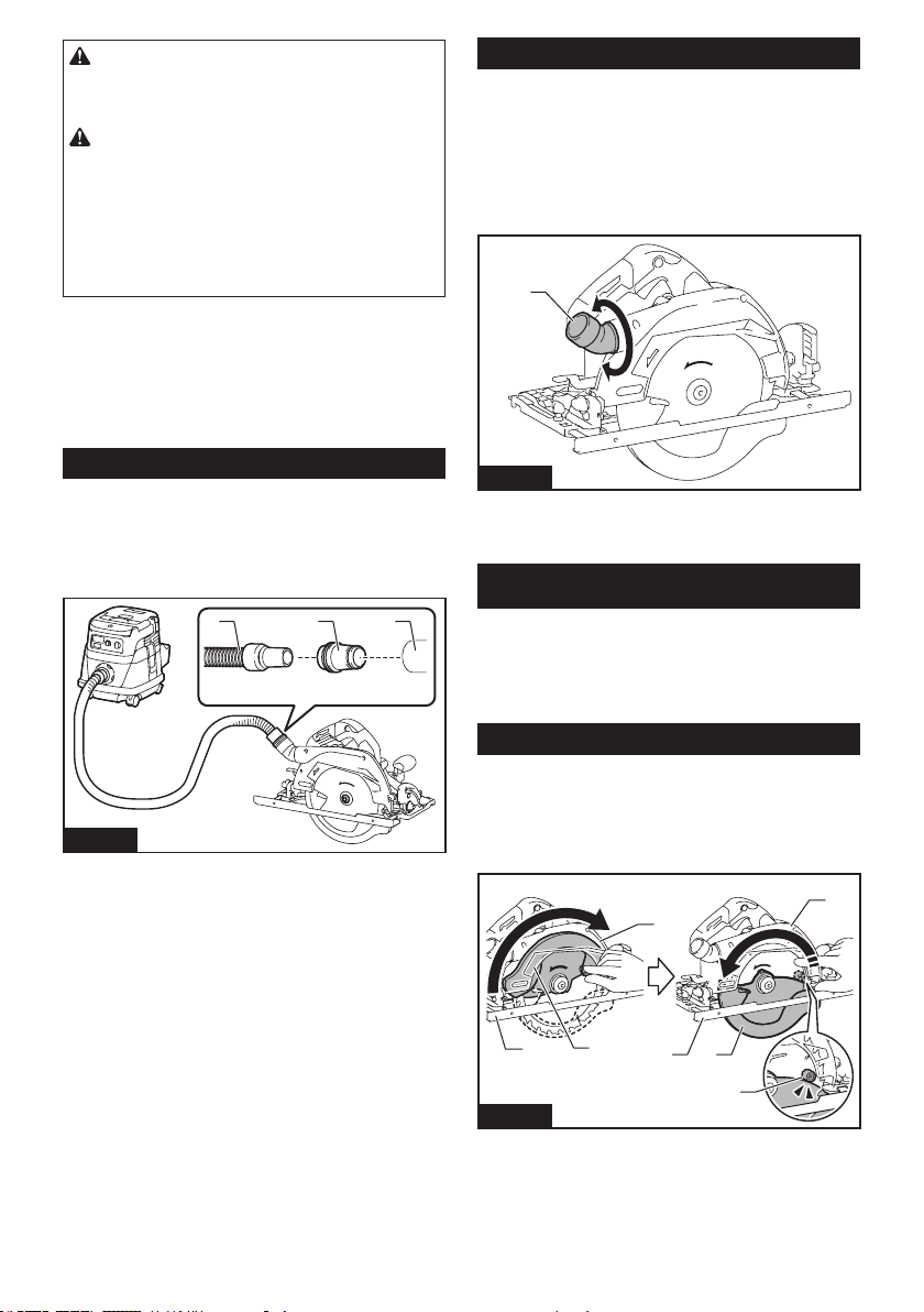
Adjusting angle of dust nozzle
Theangleofthedustnozzlecanbeadjustedbyrotating
the dust nozzle.
When operating the tool without connecting a vacuum
cleaner, bring the dust nozzle downward to prevent the
operator from being exposed to sawdust.
When operating the tool with connecting a vacuum cleaner,
bring the dust nozzle upward to keep the hose of the vacuum
cleaner from getting caught in the workpiece or the guide rail.
1
Fig.25
►1. Dust nozzle
OPERATION
Thistoolisintendedtocutwoodproductsonly.
RefertoourwebsiteorcontactyourlocalMakitadealerforthe
correct circular saw blades to be used for the material to be cut.
Do not use the tool without the sub base unless when
using the guide rail.
Checking blade guard function
Removethebatterycartridge.
Setthebevelangleto0°,andthenretractthelowerguardmanually
totheendandreleaseit.Thelowerguardisproperlyfunctioningif;
—
itisretractedabovethebasewithoutanyhindranceand;
—
itautomaticallyreturnsandcontactswiththestopper.
1
2
1
5
6
3
4
2
3
Fig.26
►1. Upper guard 2. Lower guard 3. Base 4. Stopper
5. Open 6. Close
Ifthelowerguardisnotfunctioningproperly,checkifsaw
dust is accumulated inside of the upper and lower guards. If
thelowerguardisnotfunctioningproperlyevenafterremov-
ingdust,haveyourtoolservicedataMakitaservicecenter.
14 ENGLISH
Cutting operation
CAUTION: Wear dust mask when performing
cutting operation.
CAUTION: Be sure to move the tool forward
in a straight line gently. Forcing or twisting the tool
will result in overheating the motor and dangerous
kickback,possiblycausingsevereinjury.
NOTE:Whenthebatterycartridgetemperatureis
low,thetoolmaynotworktoitsfullcapacity.Atthis
time,forexample,usethetoolforalight-dutycutfor
awhileuntilthebatterycartridgewarmsupashigh
as room temperature. Then, the tool can work to its
fullcapacity.
Fig.27
Holdthetoolrmly.Thetoolisprovidedwithbothafront
grip and rear handle. Use both to best grasp the tool.
Ifbothhandsareholdingsaw,theycannotbecutby
the circular saw blade. Set the base on the workpiece
tobecutwithoutthecircularsawblademakingany
contact. Then turn the tool on and wait until the circular
sawbladeattainsfullspeed.Nowsimplymovethetool
forwardovertheworkpiecesurface,keepingitatand
advancingsmoothlyuntilthesawingiscompleted.
Togetcleancuts,keepyoursawinglinestraightand
yourspeedofadvanceuniform.Ifthecutfailstoprop-
erlyfollowyourintendedcutline,donotattempttoturn
orforcethetoolbacktothecutline.Doingsomaybind
the circular saw blade and lead to dangerous kickback
andpossibleseriousinjury.Releaseswitch,waitforcir-
cular saw blade to stop and then withdraw tool. Realign
tool on new cut line, and start cut again. Attempt to
avoid positioning which exposes operator to chips and
wooddustbeingejectedfromsaw.Useeyeprotection
tohelpavoidinjury.
NOTE: When making a miter cuts etc., sometimes
thelowerguarddoesnotmoveeasily.Atthattime,
use the retracting lever to raise the lower guard for
starting cut and as soon as blade enters the material,
release the retracting lever.
1
Fig.28
►1. Retracting lever
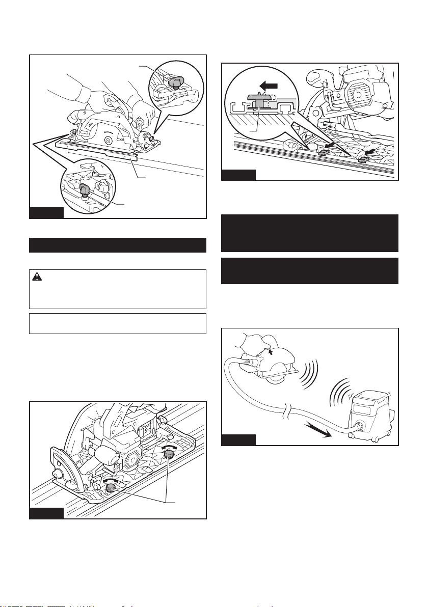
Sub base (Guide rule)
CAUTION: Make sure that the sub base (guide
rule) is securely installed in the correct position
before use.Improperattachmentmaycausedanger-
ous kickback.
Byusingthesubbaseasaguiderule,youcanperform
extra-accurate straight cuts. Loosen the clamping
screws and slide the sub base out from the tool then
insert it upside down.
1
2
Fig.29
►1. Clamping screw 2. Sub base
15 ENGLISH
Simplyslidethefenceofthesubbasesnuglyagainst
the side of the workpiece and secure it in position with
the clamping screws. It also makes repeated cuts of
uniform width possible.
1
2
1
Fig.30
►1. Clamping screw 2. Sub base
Guide rail
Optional accessory
CAUTION: Always be sure that the tool is
switched o and the battery cartridge is removed
before loosening the adjusting screws on the tool
base.
NOTICE: Remove the sub base when using the
guide rail.
Place the tool on the rear end of guide rail. Turn two
adjustingscrewsonthetoolbasesothatthetoolslides
smoothlywithoutaclatter.Holdboththefrontgripand
rearhandleofthetoolrmly.Installthebatterycar-
tridge. Turn on the tool and cut the splinter-guard along
the full length with a stroke. Now the edge of the splin-
ter-guard corresponds to the cutting edge.
1
Fig.31
►1.Adjustingscrews
When bevel cutting with the guide rail, use the slide
lever to prevent the tool from falling over.
Move the slide lever on the tool base in the direction
of arrow so that it engages the undercut groove in the
guide rail.
1
Fig.32
►1. Slide lever
WIRELESS ACTIVATION
FUNCTION
What you can do with the wireless
activation function
The wireless activation function enables clean and com-
fortableoperation.Byconnectingasupportedvacuum
cleanertothetool,youcanrunthevacuumcleaner
automaticallyalongwiththeswitchoperationofthetool.
Fig.33
To use the wireless activation function, prepare follow-
ing items:
• Awirelessunit(optionalaccessory)
• A vacuum cleaner which supports the wireless
activation function
The overview of the wireless activation function
setting is as follows. Refer to each section for detail
procedures.
1. Installing the wireless unit
2. Tool registration for the vacuum cleaner
3. Starting the wireless activation function
16 ENGLISH
Installing the wireless unit
Optional accessory
CAUTION: Place the tool on a at and stable
surface when installing the wireless unit.
NOTICE: Clean the dust and dirt on the tool
before installing the wireless unit. Dust or dirt
maycausemalfunctionifitcomesintotheslotofthe
wireless unit.
NOTICE: To prevent the malfunction caused by
static, touch a static discharging material, such
as a metal part of the tool, before picking up the
wireless unit.
NOTICE: When installing the wireless unit,
always be sure that the wireless unit is inserted
in the correct direction and the lid is completely
closed.
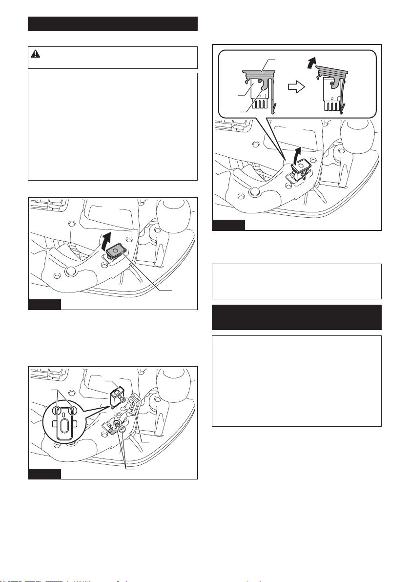
1. Openthelidonthetoolasshowninthegure.
1
Fig.34
►1. Lid
2. Insert the wireless unit to the slot and then close
the lid.
Wheninsertingthewirelessunit,aligntheprojections
with the recessed portions on the slot.
1
2
3
4
Fig.35
►1. Wireless unit 2.Projection3. Lid 4. Recessed
portion
Whenremovingthewirelessunit,openthelidslowly.
The hooks on the back of the lid will lift the wireless unit
asyoupullupthelid.
1
2
3
Fig.36
►1. Wireless unit 2. Hook 3. Lid
After removing the wireless unit, keep it in the supplied
case or a static-free container.
NOTICE: Always use the hooks on the back of
the lid when removing the wireless unit. If the
hooks do not catch the wireless unit, close the lid
completelyandopenitslowlyagain.
Tool registration for the vacuum
cleaner
NOTE: A Makita vacuum cleaner supporting the
wireless activation function is required for the tool
registration.
NOTE: Finish installing the wireless unit to the tool
before starting the tool registration.
NOTE: During the tool registration, do not pull the
switch trigger or turn on the power switch on the
vacuum cleaner.
NOTE: Refer to the instruction manual of the vacuum
cleaner, too.
Ifyouwishtoactivatethevacuumcleaneralongwith
theswitchoperationofthetool,nishthetoolregistra-
tion beforehand.
1. Install the batteries to the vacuum cleaner and the
tool.
17 ENGLISH
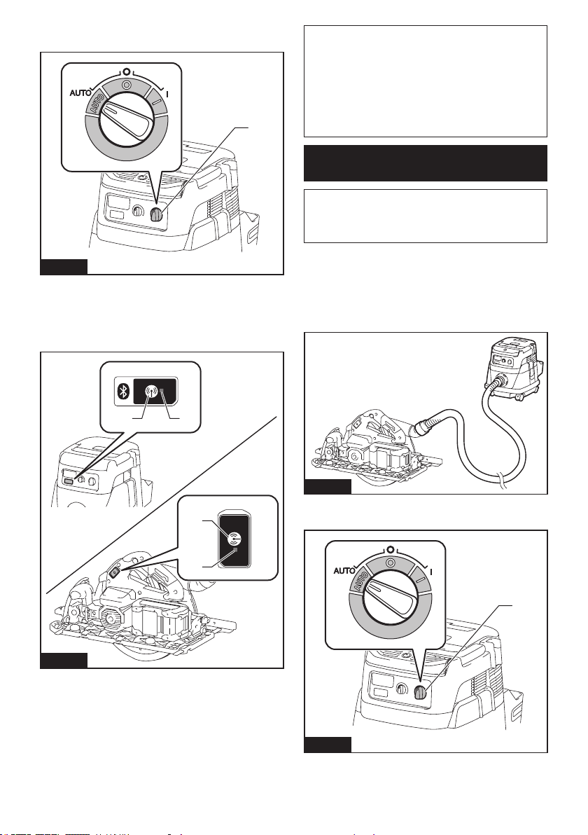
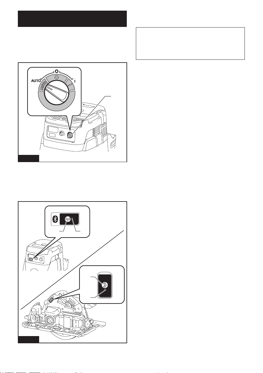
2. Setthestand-byswitchonthevacuumcleanerto
"AUTO".
1
Fig.37
►1.Stand-byswitch
3. Press the wireless activation button on the vac-
uum cleaner for 3 seconds until the wireless activation
lamp blinks in green. And then press the wireless acti-
vationbuttononthetoolinthesameway.
1 2
1
2
Fig.38
►1. Wireless activation button 2. Wireless activation
lamp
If the vacuum cleaner and the tool are linked success-
fully,thewirelessactivationlampswilllightupingreen
for 2 seconds and start blinking in blue.
NOTE:Thewirelessactivationlampsnishblinking
in green after 20 seconds elapsed. Press the wireless
activation button on the tool while the wireless acti-
vation lamp on the cleaner is blinking. If the wireless
activation lamp does not blink in green, push the wire-
lessactivationbuttonbrieyandholditdownagain.
NOTE: When performing two or more tool registra-
tionsforonevacuumcleaner,nishthetoolregistra-
tiononebyone.
Starting the wireless activation
function
NOTE: Finish the tool registration for the vacuum
cleaner prior to the wireless activation.
NOTE: Refer to the instruction manual of the vacuum
cleaner, too.
After registering a tool to the vacuum cleaner, the
vacuumcleanerwillautomaticallyrunsalongwiththe
switch operation of the tool.
1. Install the wireless unit to the tool.
2. Connect the hose of the vacuum cleaner with the
tool.
Fig.39
3. Setthestand-byswitchonthevacuumcleanerto
"AUTO".
1
Fig.40
►1.Stand-byswitch
18 ENGLISH
4. Push the wireless activation button on the tool
briey.Thewirelessactivationlampwillblinkinblue.
1
2
Fig.41
►1. Wireless activation button 2. Wireless activation
lamp
5.
Pull the switch trigger of the tool. Check if the vacuum
cleaner runs while the switch trigger is being pulled.
To stop the wireless activation of the vacuum cleaner,
push the wireless activation button on the tool.
NOTE: The wireless activation lamp on the tool will
stop blinking in blue when there is no operation for
2hours.Inthiscase,setthestand-byswitchonthe
vacuum cleaner to "AUTO" and push the wireless
activation button on the tool again.
NOTE:Thevacuumcleanerstarts/stopswithadelay.
There is a time lag when the vacuum cleaner detects
a switch operation of the tool.
NOTE:
Thetransmissiondistanceofthewirelessunitmay
varydependingonthelocationandsurroundingcircumstances.
NOTE: When two or more tools are registered to one
vacuumcleaner,thevacuumcleanermaystartrun-
ningevenifyoudonotpulltheswitchtriggerbecause
another user is using the wireless activation function.
Description of the wireless activation lamp status
1
Fig.42
►1. Wireless activation lamp
The wireless activation lamp shows the status of the wireless activation function. Refer to the table below for the
meaning of the lamp status.
Status Wireless activation lamp Description
Color
On
Blinking
Duration
Standby Blue
2 hours The wireless activation of the vacuum cleaner is available. The
lampwillautomaticallyturnowhennooperationisperformed
for 2 hours.
When
the tool is
running.
The wireless activation of the vacuum cleaner is available and the
tool is running.
Tool
registration
Green
20 seconds Readyforthetoolregistration.Waitingfortheregistrationbythe
vacuum cleaner.
2 seconds Thetoolregistrationhasbeennished.Thewirelessactivation
lamp will start blinking in blue.
Cancelling
tool
registration
Red
20 seconds Readyforthecancellationofthetoolregistration.Waitingforthe
cancellationbythevacuumcleaner.
2 seconds Thecancellationofthetoolregistrationhasbeennished.The
wireless activation lamp will start blinking in blue.
Others Red
3 seconds The power is supplied to the wireless unit and the wireless activa-
tion function is starting up.
O - - The wireless activation of the vacuum cleaner is stopped.
19 ENGLISH
Cancelling tool registration for the
vacuum cleaner
Perform the following procedure when cancelling the
tool registration for the vacuum cleaner.
1.
Install the batteries to the vacuum cleaner and the tool.
2. Setthestand-byswitchonthevacuumcleanerto
"AUTO".
1
Fig.43
►1.Stand-byswitch
3. Press the wireless activation button on the vac-
uum cleaner for 6 seconds. The wireless activation
lamp blinks in green and then become red. After that,
press the wireless activation button on the tool in the
sameway.
1 2
1
2
Fig.44
►1. Wireless activation button 2. Wireless activation
lamp
Ifthecancellationisperformedsuccessfully,thewire-
less activation lamps will light up in red for 2 seconds
and start blinking in blue.
NOTE:Thewirelessactivationlampsnishblinkingin
red after 20 seconds elapsed. Press the wireless acti-
vation button on the tool while the wireless activation
lamp on the cleaner is blinking. If the wireless acti-
vation lamp does not blink in red, push the wireless
activationbuttonbrieyandholditdownagain.

20 ENGLISH
Troubleshooting for wireless activation function
Beforeaskingforrepairs,conductyourowninspectionrst.Ifyoundaproblemthatisnotexplainedinthemanual,
donotattempttodismantlethetool.Instead,askMakitaAuthorizedServiceCenters,alwaysusingMakitareplace-
ment parts for repairs.
State of abnormality Probable cause (malfunction) Remedy
The wireless activation lamp does
not light/blink.
The wireless unit is not installed into the tool.
Thewirelessunitisimproperlyinstalled
into the tool.
Installthewirelessunitcorrectly.
The terminal of the wireless unit and/or
theslotisdirty.
Gentlywipeodustanddirtontheterminalofthe
wireless unit and clean the slot.
The wireless activation button on the
tool has not been pushed.
Push the wireless activation button on the tool
briey.
Thestand-byswitchonthevacuum
cleaner is not set to "AUTO".
Setthestand-byswitchonthevacuumcleanerto
"AUTO".
Nopowersupply
Supplythepowertothetoolandthevacuumcleaner.
Cannotnishtoolregistration/can-
cellingtoolregistrationsuccessfully.
The wireless unit is not installed into the tool.
Thewirelessunitisimproperlyinstalled
into the tool.
Installthewirelessunitcorrectly.
The terminal of the wireless unit and/or
theslotisdirty.
Gentlywipeodustanddirtontheterminalofthe
wireless unit and clean the slot.
Thestand-byswitchonthevacuum
cleaner is not set to "AUTO".
Setthestand-byswitchonthevacuumcleanerto
"AUTO".
Nopowersupply
Supplythepowertothetoolandthevacuumcleaner.
Incorrect operation
Pushthewirelessactivationbuttonbrieyandperform
the tool registration/cancellation procedures again.
Thetoolandvacuumcleanerareaway
from each other (out of the transmission
range).
Get the tool and vacuum cleaner closer to each other.
Themaximumtransmissiondistanceisapproximately10
mhoweveritmayvaryaccordingtothecircumstances.
Beforenishingthetoolregistration/cancellation;
- the switch trigger on the tool is pulled or;
- the power button on the vacuum
cleaner is turned on.
Pushthewirelessactivationbuttonbrieyand
perform the tool registration/cancellation procedures
again.
The tool registration procedures for the
toolorvacuumcleanerhavenotnished.
Perform the tool registration procedures for both the
tool and the vacuum cleaner at the same timing.
Radiodisturbancebyotherappliances
whichgeneratehigh-intensityradio
waves.
Keepthetoolandvacuumcleanerawayfromthe
appliances such as Wi-Fi devices and microwave
ovens.
The vacuum cleaner does not run
along with the switch operation of
the tool.
The wireless unit is not installed into the tool.
Thewirelessunitisimproperlyinstalled
into the tool.
Installthewirelessunitcorrectly.
The terminal of the wireless unit and/or
theslotisdirty.
Gentlywipeodustanddirtontheterminalofthe
wireless unit and clean the slot.
The wireless activation button on the
tool has not been pushed.
Pushthewirelessactivationbuttonbrieyandmake
sure that the wireless activation lamp is blinking in blue.
Thestand-byswitchonthevacuum
cleaner is not set to "AUTO".
Setthestand-byswitchonthevacuumcleanerto
"AUTO".
More than 10 tools are registered to the
vacuum cleaner.
Perform the tool registration again.
If more than 10 tools are registered to the vacuum
cleaner, the tool registered earliest will be cancelled
automatically.
The vacuum cleaner erased all tool
registrations.
Perform the tool registration again.
Nopowersupply
Supplythepowertothetoolandthevacuumcleaner.
Thetoolandvacuumcleanerareaway
from each other (out of the transmission
range).
Get the tool and vacuum cleaner closer each other. The
maximumtransmissiondistanceisapproximately10m
howeveritmayvaryaccordingtothecircumstances.
Radiodisturbancebyotherappliances
whichgeneratehigh-intensityradio
waves.
Keepthetoolandvacuumcleanerawayfromthe
appliances such as Wi-Fi devices and microwave
ovens.
The vacuum cleaner runs while the
tool's switch trigger is not pulled.
Other users are using the wireless
activation of the vacuum cleaner with
their tools.
Turnothewirelessactivationbuttonoftheother
tools or cancel the tool registration of the other
tools.
21 ENGLISH
MAINTENANCE
CAUTION: Always be sure that the tool is
switched o and the battery cartridge is removed
before attempting to perform inspection or
maintenance.
CAUTION: Clean out the upper and lower
guards to ensure there is no accumulated saw-
dust which may impede the operation of the lower
guarding system.Adirtyguardingsystemmaylimit
the proper operation which could result in serious
personalinjury.Themosteectivewaytoaccomplish
this cleaning is with compressed air. If the dust is
being blown out of the guards, be sure the proper
eye and breathing protection is used.
CAUTION: After each use, wipe o the saw
dust on the tool.Finesawdustmaycomeinsidethe
toolandcausemalfunctionorare.
NOTICE: Never use gasoline, benzine, thinner,
alcohol or the like. Discoloration, deformation or
cracks may result.
To maintain product SAFETY and RELIABILITY,
repairs,anyothermaintenanceoradjustmentshould
beperformedbyMakitaAuthorizedorFactoryService
Centers,alwaysusingMakitareplacementparts.
Adjusting 0°-cut or 45°-cut accuracy
NOTICE: Do not engage the levers for -1° bevel
angle when adjusting 0°-cut accuracy.
NOTICE: Do not engage the positive stopper for
22.5° or 60° bevel angle when adjusting 45°-cut
accuracy.
Thisadjustmenthasbeenmadeatthefactory.Butifitis
o,youcanadjustitasthefollowingprocedure.
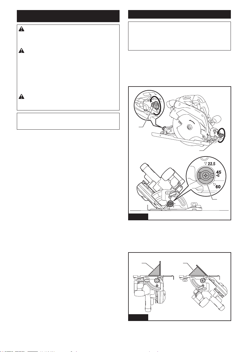
1. Loosen the clamping screws on the front and rear
of the tool so that the bevel angle can be changed. Set
thepositivestopperto45°bevelanglepositionifyou
aregoingtoadjust45°-cutaccuracy.
1
1
2
Fig.45
►1. Clamping screw 2. Positive stopper
2. Make the base perpendicular or 45° to the circular
sawbladeusingatriangularrulebyturningtheadjust-
ing screw with a hex wrench. You can also use a square
ruletoadjust0°angle.
1 1
Fig.46
►1. Triangular rule
22 ENGLISH
1
2
Fig.47
►1.Adjustingscrewfor0°angle2.Adjustingscrew
for 45° angle
3. Tighten the clamping screws and then make a test
cut to check if desired angle is obtained.
Adjusting the depth guide
Ifthebasedoesnotslideupordownsmoothly,the
depthguidemayhavebeentilted.Youcanadjustthe
depth guide as follows:
1. Make the base perpendicular, and set the depth of
cut to the deepest.
2. Loosentheadjustingscrewsforthedepthguide.
Thedepthguideautomaticallyadjustsitsposition.
3. Tightentheadjustingscrewsforthedepthguide.
4. Adjusttheparallelismbyreferringtothesection
for parallelism.
1
Fig.48
►1.Adjustingscrewsforthedepthguide
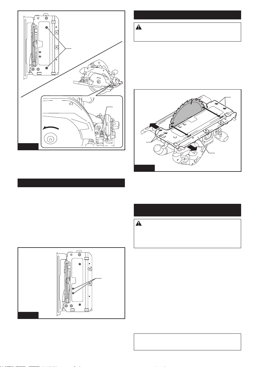
Adjusting the parallelism
CAUTION:
Keep the parallelism accurate.
Otherwisethecircularsawblademaybiteintotheguide
railandthedamagedguiderailmaycauseaninjury.
Thisadjustmenthasbeenmadeatthefactory.Butifitis
o,youcanadjustitasthefollowingprocedure.
1. Set the tool to the maximum cutting depth.
2. Make sure all levers and screws are tightened.
3. Loosenthescrewsshowninthegure.
4. While opening the lower guard, move the rear of
the base so that the distance A and B becomes equal.
1
1
2
A
B
Fig.49
►1. Screw 2. Base
5. Tighten the screws and make a test cut to check
the parallelism.
OPTIONAL ACCESSORIES
CAUTION:
These accessories or attachments
are recommended for use with your Makita tool spec-
ied in this manual.Theuseofanyotheraccessories
orattachmentsmightpresentariskofinjurytopersons.
Onlyuseaccessoryorattachmentforitsstatedpurpose.
Ifyouneedanyassistanceformoredetailsregarding
theseaccessories,askyourlocalMakitaServiceCenter.
• Circular saw blade
• Sub base
• Guide rail
• Bevel guide
• Clamp
• Sheet
• Rubber sheet
• Position sheet
• Hex wrench
• Frontcu24
• Wireless unit
• Makitagenuinebatteryandcharger
NOTE:Someitemsinthelistmaybeincludedinthe
toolpackageasstandardaccessories.Theymay
dierfromcountrytocountry.

23 ENGLISH
MAKITA LIMITED WARRANTY
Pleaserefertotheannexedwarrantysheetforthe
mostcurrentwarrantytermsapplicabletothisproduct.
Ifannexedwarrantysheetisnotavailable,refertothe
warrantydetailssetforthatbelowwebsiteforyour
respectivecountry.
United States of America: www.makitatools.com
Canada: www.makita.ca
Other countries: www.makita.com
24 ESPAÑOL
ESPAÑOL (Instrucciones originales)
ESPECIFICACIONES
Modelo: GSH03
Diámetro del disco 235mm(9-1/4″)
Profundidad de corte máxima a 0° 85mm(3-3/8″)
bisel a 45° 61mm(2-3/8″)
bisel a 60° 44mm(1-3/4″)
Velocidad sin carga 4 000 r/min
Longitud total 413mm(16-1/4″)
Tensión nominal 36 V - 40 V c.c. máx.
Peso neto 5,1 kg - 5,7 kg (11,2 lbs - 12,6 lbs)
• Debidoanuestrocontinuoprogramadeinvestigaciónydesarrollo,lasespecicacionesaquíincluidasestán
sujetasacambiosinprevioaviso.
• Lasespecicacionesyelcartuchodebateríapuedenvariardepaísapaís.
• Elpesopuedevariarenfuncióndelosaccesorios,incluidoelcartuchodebatería.Enlatablasemuestrala
combinacióndepesomásligeroymáspesadoconformealprocedimiento01/2014deEPTA.
Cartucho de batería y cargador aplicables
Cartuchodebatería BL4020 / BL4025 / BL4040 / BL4050F*
*:Bateríarecomendada
Cargador DC40RA / DC40RB / DC40RC
• Algunosdeloscartuchosdebateríaycargadoresenumeradosarribapodríannoestardisponiblesdepen-
diendo de su área de residencia.
ADVERTENCIA: Use únicamente los cartuchos de batería y los cargadores indicados arriba. El uso de
cualquierotrocartuchodebateríaycargadorpodríaocasionarunalesióny/ounincendio.
ADVERTENCIAS DE
SEGURIDAD
Advertencias generales de seguridad
para herramientas eléctricas
ADVERTENCIA:
Lea todas las advertencias de
seguridad, instrucciones, ilustraciones y especicaciones
suministradas con esta herramienta eléctrica. El no seguir
todaslasinstruccionesindicadasacontinuaciónpodríaoca-
sionarunadescargaeléctrica,incendioy/olesionesgraves.
Conserve todas las advertencias
e instrucciones como referencia
en el futuro.
En las advertencias, el término “herramienta eléctrica” se
reereasuherramientaeléctricadefuncionamientocon
conexión a la red eléctrica (con cableado eléctrico) o herra-
mientaeléctricadefuncionamientoabatería(inalámbrica).
Seguridad en el área de trabajo
1. Mantenga el área de trabajo limpia y bien ilu-
minada. Las áreas oscuras o desordenadas son
propensas a accidentes.
2. No utilice las herramientas eléctricas en
atmósferas explosivas, tal como en la presen-
cia de líquidos, gases o polvo inamables. Las
herramientas eléctricas crean chispas que pueden
prender fuego al polvo o los humos.
3. Mantenga a los niños y curiosos alejados
mientras utiliza una herramienta eléctrica. Las
distracciones le pueden hacer perder el control.
Seguridad eléctrica
1. Las clavijas de conexión de las herramientas
eléctricas deberán encajar perfectamente en la
toma de corriente. No modique nunca la cla-
vija de conexión de ninguna forma. No utilice
ninguna clavija adaptadora con herramientas
eléctricas que tengan conexión a tierra (puesta
a tierra). Lautilizacióndeclavijasnomodica-
dasyqueencajenperfectamenteenlatomade
corriente reducirá el riesgo de que se produzca
una descarga eléctrica.
2.
Evite tocar con el cuerpo supercies conectadas
a tierra o puestas a tierra tales como tubos, radia-
dores, cocinas y refrigeradores. Si su cuerpo es
puestoatierraoconectadoatierraexistiráunmayor
riesgo de que sufra una descarga eléctrica.
3. No exponga las herramientas eléctricas a la
lluvia ni a condiciones húmedas. La entrada de
agua en una herramienta eléctrica aumentará el
riesgo de que se produzca una descarga eléctrica.

25 ESPAÑOL
4. No maltrate el cable. Nunca utilice el cable
para transportar, jalar o desconectar la herra-
mienta eléctrica. Mantenga el cable alejado del
calor, aceite, objetos cortantes o piezas móvi-
les. Los cables dañados o enredados aumentan
el riesgo de sufrir una descarga eléctrica.
5.
Cuando utilice una herramienta eléctrica en
exteriores, utilice un cable de extensión apro-
piado para uso en exteriores. La utilización de un
cable apropiado para uso en exteriores reducirá el
riesgo de que se produzca una descarga eléctrica.
6. Si no es posible evitar usar una herramienta
eléctrica en condiciones húmedas, utilice un
alimentador protegido con interruptor de cir-
cuito de falla a tierra (ICFT). El uso de un ICFT
reduce el riesgo de descarga eléctrica.
7. Las herramientas eléctricas pueden producir
campos electromagnéticos (CEM) que no son
dañinos para el usuario. Sin embargo, si los
usuariostienenmarcapasosyotrosdispositivos
médicos similares, deberán consultar al fabricante
desudispositivoy/oasumédicoantesdeoperar
esta herramienta eléctrica.
Seguridad personal
1. Manténgase alerta, preste atención a lo que
está haciendo y utilice su sentido común
cuando opere una herramienta eléctrica. No
utilice una herramienta eléctrica cuando esté
cansado o bajo la inuencia de drogas, alco-
hol o medicamentos. Un momento de distracción
mientras opera las herramientas eléctricas puede
terminar en una lesión grave.
2. Use equipo de protección personal. Póngase
siempre protección para los ojos. El equipo
protector tal como máscara contra el polvo, zapa-
tosdeseguridadantiderrapantes,cascorígidoy
protecciónparaoídosutilizadoenlascondiciones
apropiadas reducirá el riesgo de lesiones.
3.
Impida el encendido accidental. Asegúrese de
que el interruptor esté en la posición de apa-
gado antes de conectar a la alimentación eléc-
trica y/o de colocar el cartucho de batería, así
como al levantar o cargar la herramienta. Cargar
las herramientas eléctricas con su dedo en el inte-
rruptor o enchufarlas con el interruptor encendido
hace que los accidentes sean comunes.
4. Retire cualquier llave de ajuste o llave de
apriete antes de encender la herramienta. Una
llavedeajusteollavedeaprietequehayasido
dejadapuestaenunapartegiratoriadelaherra-
mienta eléctrica puede ocasionar alguna lesión.
5.
No utilice la herramienta donde no alcance.
Mantenga los pies sobre suelo rme y el equilibrio
en todo momento.Estopermiteunmejorcontrolde
la herramienta eléctrica en situaciones inesperadas.
6.
Use una vestimenta apropiada. No use ropa suelta
ni alhajas. Mantenga el cabello, la ropa y los guan-
tes alejados de las piezas móviles. Las prendas de
vestirholgadas,lasalhajasyelcabellolargosuelto
podríanengancharseenestaspiezasmóviles.
7.
Si dispone de dispositivos para la conexión de
equipos de extracción y recolección de polvo,
asegúrese de conectarlos y utilizarlos debida-
mente. Hacer uso de la recolección de polvo puede
reducir los riesgos relacionados con el polvo.
8. No permita que la familiaridad adquirida
debido al uso frecuente de las herramientas
haga que se sienta conado e ignore los prin-
cipios de seguridad de las herramientas. Un
descuidopodríaocasionarunalesióngraveen
una fracción de segundo.
9. Utilice siempre gafas protectoras para prote-
ger sus ojos de lesiones al usar herramientas
eléctricas. Las gafas deben cumplir con la
Norma ANSI Z87.1 en EUA.
Es responsabilidad del empleador imponer
el uso de equipos protectores de seguridad
apropiados a los operadores de la herramienta
y demás personas cerca del área de trabajo.
Mantenimiento y uso de la herramienta eléctrica
1. No fuerce la herramienta eléctrica. Utilice la
herramienta eléctrica correcta para su aplica-
ción. La herramienta eléctrica adecuada hará un
mejortrabajoydeformamásseguraalaveloci-
dad para la que ha sido fabricada.
2. No utilice la herramienta eléctrica si el inte-
rruptor no la enciende y apaga. Cualquier
herramienta eléctrica que no pueda ser contro-
ladaconelinterruptorespeligrosaydebeser
reemplazada.
3. Desconecte la clavija de la fuente de alimen-
tación y/o retire la batería de la herramienta
eléctrica, en caso de ser removible, antes de
realizar ajustes, cambiar accesorios o almace-
nar las herramientas eléctricas. Tales medidas
de seguridad preventivas reducirán el riesgo
de poner en marcha la herramienta eléctrica de
forma accidental.
4. Guarde la herramienta eléctrica que no use
fuera del alcance de los niños y no permita
que las personas que no están familiarizadas
con ella o con las instrucciones la operen. Las
herramientas eléctricas son peligrosas en manos
de personas que no saben operarlas.
5. Dé mantenimiento a las herramientas eléctri-
cas y los accesorios. Compruebe que no haya
piezas móviles desalineadas o estancadas,
piezas rotas y cualquier otra condición que
pueda afectar al funcionamiento de la herra-
mienta eléctrica. Si la herramienta eléctrica
está dañada, haga que la reparen antes de
utilizarla. Muchos de los accidentes son ocasio-
nados por no dar un mantenimiento adecuado a
las herramientas eléctricas.
6.
Mantenga las herramientas de corte limpias y
losas.Sirecibeunmantenimientoadecuadoytiene
losbordesalados,esprobablequelaherramienta
seatasquemenosyseamásfácilcontrolarla.
7.
Utilice la herramienta eléctrica, los accesorios y
las brocas de acuerdo con estas instrucciones,
considerando las condiciones laborales y el
trabajo a realizar. Si utiliza la herramienta eléctrica
para realizar operaciones distintas de las indicadas,
podrá presentarse una situación peligrosa.
8. Mantenga los mangos y supercies de asi-
miento secos, limpios y libres de aceite o
grasa.Losmangosysuperciesdeasimiento
resbalosos no permiten una manipulación segura
ni el control de la herramienta en situaciones
inesperadas.
26 ESPAÑOL
9. Cuando vaya a utilizar esta herramienta, evite
usar guantes de trabajo de tela ya que éstos
podrían atorarse.Silosguantesdetrabajode
tela llegaran a atorarse en las piezas móviles,
estopodríaocasionarlesionespersonales.
Uso y cuidado de la herramienta a batería
1. Recargue sólo con el cargador especicado
por el fabricante. Un cargador que es adecuado
paraunsolotipodebateríapuedegenerarriesgo
deincendioalserutilizadoconotrabatería.
2. Utilice las herramientas eléctricas solamente
con las baterías designadas especícamente
para ellas.Lautilizacióndecualquierotrabatería
puede crear un riesgo de lesiones o incendio.
3. Cuando no se esté usando la batería, mantén-
gala alejada de otros objetos metálicos, como
sujetapapeles (clips), monedas, llaves, clavos,
tornillos u otros objetos pequeños de metal
los cuales pueden actuar creando una cone-
xión entre las terminales de la batería. Originar
un cortocircuito en las terminales puede causar
quemaduras o incendios.
4. En condiciones abusivas, podrá escapar
líquido de la batería; evite tocarlo. Si lo toca
accidentalmente, enjuague con agua. Si hay
contacto del líquido con los ojos, busque asis-
tencia médica.Puedequeellíquidoexpulsado
delabateríacauseirritaciónoquemaduras.
5. No utilice una herramienta ni una batería que
estén dañadas o hayan sido modicadas. Las
bateríasdañadasomodicadaspodríanoca-
sionar una situación inesperada provocando un
incendio, explosión o riesgo de lesiones.
6. No exponga la herramienta ni la batería al
fuego ni a una temperatura excesiva. La expo-
sición al fuego o a una temperatura superior a los
130°Cpodríacausarunaexplosión.
7. Siga todas las instrucciones para la carga y
evite cargar la herramienta o la batería fuera
del rango de temperatura especicado en
las instrucciones. Una carga inadecuada o a
unatemperaturafueradelrangoespecicado
podríadañarlabateríaeincrementarelriesgode
incendio.
Servicio
1. Haga que una persona calicada repare la
herramienta eléctrica utilizando sólo piezas de
repuesto idénticas. Esto asegura que se man-
tenga la seguridad de la herramienta eléctrica.
2. Nunca dé servicio a baterías que estén daña-
das.Elservicioalasbateríassolamentedeberá
ser efectuado por el fabricante o un agente de
servicio autorizado.
3. Siga las instrucciones para la lubricación y
cambio de accesorios.
4. No modique ni intente reparar el aparato ni el
paquete de baterías salvo como se indique en
las instrucciones para el uso y cuidado.
Advertencias de seguridad para la
sierra circular inalámbrica
Procedimientos de corte
1.
PELIGRO: Mantenga las manos alejadas
del área de corte y del disco. Mantenga su
segunda mano sobre el mango auxiliar o sobre
la carcasa del motor.Siambasmanossujetanla
sierra no pueden sufrir cortes del disco.
2. Nunca meta la mano por debajo de la pieza
de trabajo. El protector no puede protegerle del
discodebajodelapiezadetrabajo.
3. Ajuste la profundidad de corte al grosor de la
pieza de trabajo. Debe verse menos de un diente
completopordebajodelapiezadetrabajo.
4. Nunca sostenga la pieza de trabajo con sus
manos ni a través de su pierna durante el
corte. Asegure la pieza de trabajo a una plata-
forma estable.Esimportanteapoyarlapiezade
trabajoadecuadamenteparareducirlaexposición
del cuerpo, el atascamiento del disco o la pérdida
de control.
Fig.1
5. Cuando realice una operación en la que la
herramienta de corte pueda entrar en contacto
con cableado oculto, sujete la herramienta
eléctrica por las supercies de asimiento
aisladas. El contacto con un cable con corriente
también hará que la corriente circule por las par-
tes metálicas expuestas de la herramienta eléc-
tricaypodríaocasionarunadescargaeléctricaal
operador.
6. Cuando realice un corte longitudinal, utilice
siempre un tope lateral de corte o una guía de
borde recto.Estomejoralaprecisióndelcortey
reduce la posibilidad de que el disco se atasque.
7. Utilice siempre discos del tamaño y forma
correctos (diamante versus circular) de los
oricios para ejes.Losdiscosquenoencajen
conelequipodemontajedelasierrasedesequili-
brarán ocasionando la pérdida de control.
8. Nunca utilice arandelas o pernos de disco
dañados o incorrectos.Elpernoylasarandelas
deldiscosehandiseñadoespecícamentepara
susierra,paraunaseguridadyunrendimiento
óptimos.
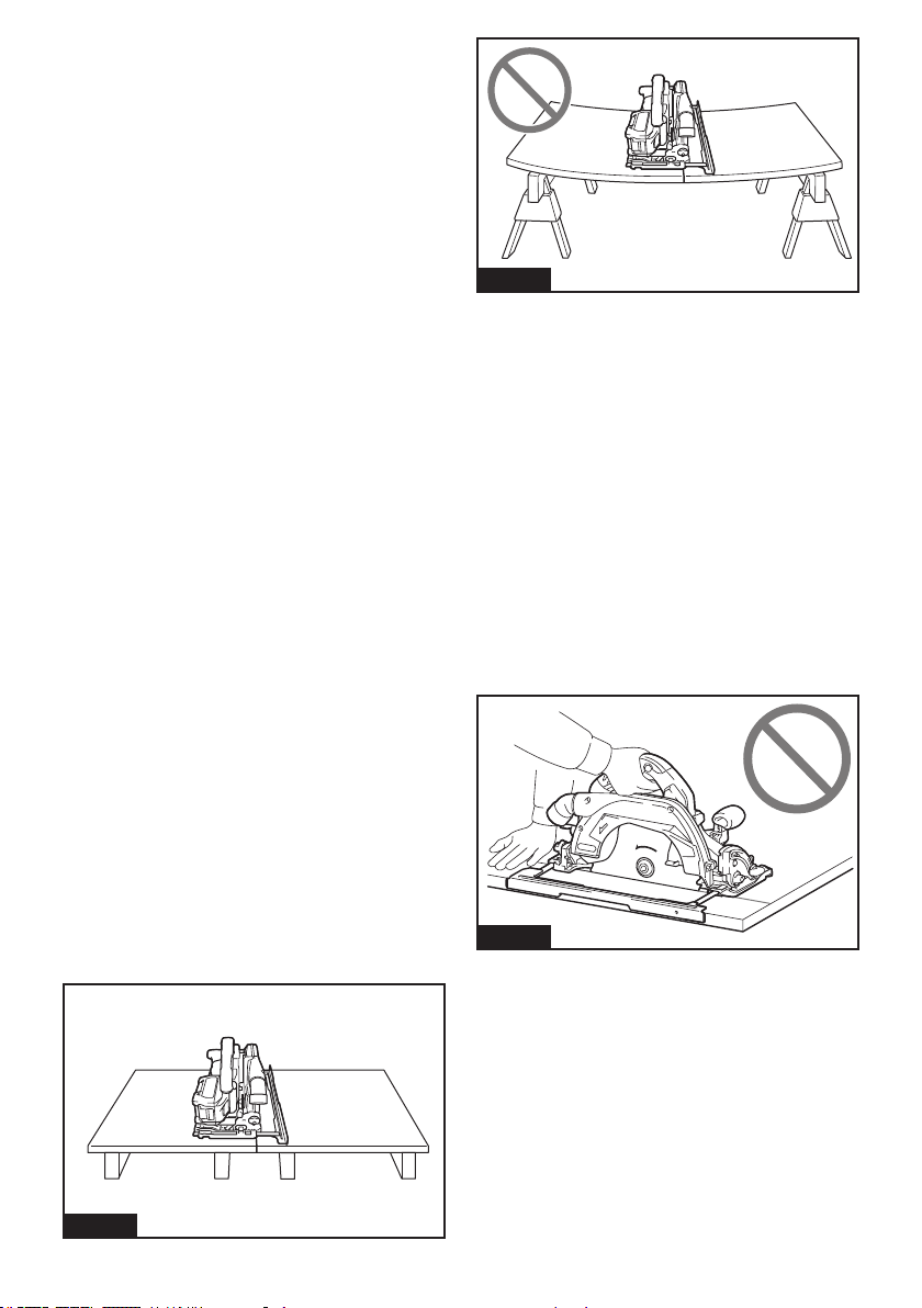
27 ESPAÑOL
Causas de los retrocesos bruscos y advertencias relacionadas
— el retroceso brusco es una reacción repentina
a un disco de la sierra pellizcado, atascado o
desalineado, que ocasiona que una sierra des-
controladaselevanteylapiezadetrabajosalga
disparada hacia el operador;
— cuando el disco queda fuertemente pellizcado o
atascadoalcerrarselalíneadecorte,eldiscose
detieneylareaccióndelmotoresdirigirrápida-
mente la unidad hacia el operador;
— si el disco se retuerce o está mal alineado en el
corte, los dientes del borde posterior del disco
puedenclavarseenlasupercieposteriordela
madera,haciendoqueeldiscoescalelalíneade
corteysaltehaciaeloperador.
El retroceso brusco es el resultado de un mal uso de
lasierray/odecondicionesoprocedimientosdeuso
incorrectosysepuedeevitartomandolasprecauciones
que se indican a continuación.
1. Sujete la sierra rmemente con las dos manos
y coloque sus brazos de forma que ofrezcan
resistencia a la fuerza del retroceso brusco.
Coloque su cuerpo hacia cualquiera de los
lados del disco, pero no en línea con él. El
retroceso brusco puede provocar que la sierra
salte hacia atrás; no obstante, el operador puede
controlar la fuerza del retroceso brusco si toma las
precauciones adecuadas.
2. Cuando note que el disco se atora, o cuando
quiera interrumpir un corte por cualquier
razón, suelte el gatillo y mantenga la sierra
inmóvil en el material hasta que el disco se
pare completamente. No intente nunca extraer
la sierra de la pieza de trabajo ni tirar de la sie-
rra hacia atrás mientras el disco esté movién-
dose porque podrá ocasionar un retroceso
brusco.Investigueytomemedidascorrectivas
para eliminar la causa del atoramiento del disco.
3. Cuando reinicie la sierra en la pieza de trabajo,
centre el disco de la sierra en la línea de corte
de manera que los dientes de la sierra no que-
den enganchados en el material. Si el disco de
lasierrallegaraatrabarse,éstepodríalevantarse
ysufrirunretrocesobruscodesdelapiezade
trabajoalreiniciarselasierra.
4. Sujete los paneles grandes para minimizar el
riesgo de que el disco se estanque y dé un
retroceso brusco. Los paneles grandes tienden
ahundirsebajosupropiopeso.Debencolocarse
soportesbajoelpanelenamboslados,cercade
lalíneadecorteydelbordedelpanel.
Fig.2
Fig.3
5.
No utilice discos dañados o desalados. Las
discoscolocadosincorrectamenteodesalados
producenuncortemásangostoycausanunafricción
excesiva,queeldiscosedobleyretrocesosbruscos.
6. Las palancas de jación de los ajustes de pro-
fundidad y de bisel del disco deben ser apreta-
das y aseguradas antes de realizar el corte. Si
elajustedeldiscocambiaduranteelcorte,podrá
ocasionarunatoramientoyretrocesobrusco.
7. Tenga especial cuidado cuando realice cortes
con sierra en paredes existentes u otras áreas
ciegas.Eldiscoprotuberantepuedecortarobje-
tos que pueden provocar retrocesos bruscos.
8.
SIEMPRE sostenga rmemente la herramienta
con ambas manos. NUNCA coloque su mano,
pierna ni cualquier parte de su cuerpo debajo de
la base de la herramienta ni detrás de la sierra,
especialmente al hacer cortes longitudinales. Si
se llega a dar un retroceso brusco, la herramienta
podríafácilmentesaltarhaciaatrássobresumano,
ocasionando lesiones personales graves.
Fig.4
9.
Nunca fuerce la sierra. Empuje la sierra hacia
adelante a una velocidad a la que el disco corte
sin desacelerarse. Forzar la sierra durante el corte
puede producir cortes desiguales, perder precisión
yposiblementegenerarunretrocesobrusco.
Función del protector
1.
Compruebe que el protector inferior esté bien
cerrado antes de cada uso. No utilice la sierra si el
protector inferior no se mueve libremente y se cie-
rra instantáneamente. Nunca sujete ni mantenga
el protector inferior en la posición abierta. Si la sie-
rra cae accidentalmente, el protector inferior se puede
doblar. Levante el protector inferior con el mango
retráctilyasegúresedequesemuevelibrementeyde
que no hace contacto con el disco ni con ninguna otra
piezaentodoslosángulosyprofundidadesdecorte.
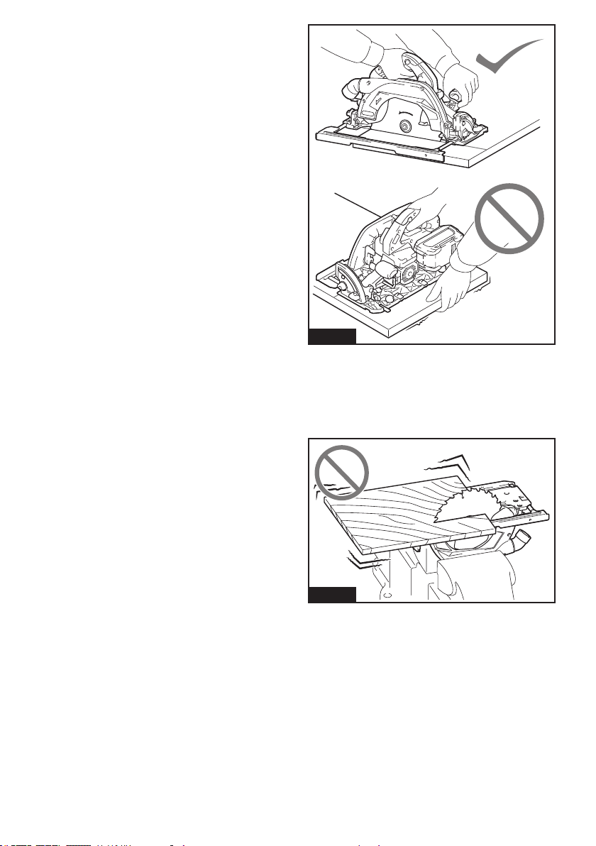
28 ESPAÑOL
2. Compruebe el funcionamiento del muelle del
protector inferior. Si el protector y el muelle
no funcionan correctamente, deben repararse
antes de utilizar la herramienta. El protector
inferior puede funcionar con lentitud debido a las
piezasdañadas,depósitospegajososoacumula-
ción de suciedad.
3. El protector inferior debe retraerse manual-
mente sólo para cortes especiales tales como
“cortes de inmersión” y “cortes compues-
tos”. Levante el protector inferior mediante
el mango retráctil y cuando el disco entre en
el material, debe soltar el protector inferior.
Para todos los otros cortes con sierra, el protector
inferior debe funcionar automáticamente.
4. Antes de dejar la sierra en el banco o en
el suelo, observe siempre que el protector
inferior esté cubriendo el disco. Un disco des-
protegido, girando por inercia, hará que la sierra
se desplace hacia atrás, cortando todo lo que
encuentre a su paso. Tenga presente el tiempo
que el disco tarda en detenerse después de soltar
el interruptor.
5. Para revisar el protector inferior, ábralo
manualmente, suéltelo y vea que cierre. Revise
también que el mango retráctil no toque el
alojamiento de la herramienta.Dejareldisco
expuestoesMUYPELIGROSOypuedeocasio-
nar lesiones personales graves.
Advertencias de seguridad adicionales
1. Uso pretendido
Esta herramienta está diseñada para cortar
productos de madera por medio de cortes rec-
tos longitudinales y transversales, así como
cortes en inglete con ángulos, mientras está
apoyada rmemente con la pieza de trabajo.
Laacumulacióndeaserrínenelprotectorinferior
yelejegeneradaporotrosmaterialespuede
afectarelcierrecorrectodelprotectorinferiory
ocasionar lesiones personales graves.
2. Proceda con extrema precaución al cortar
madera húmeda, tratada a presión o con
nudos. Mantenga un avance suave de la herra-
mienta sin reducir la velocidad del disco para
evitar el sobrecalentamiento de las puntas del
mismo.
3. No intente retirar material cortado cuando el
disco se está moviendo. Espere hasta que el
disco se detenga antes de recoger el material
cortado. Los discos siguen girando por inercia
después de apagar la herramienta.
4. Evite cortar clavos. Inspeccione la madera
y quite todos los clavos antes de realizar el
corte.
5. Coloque la parte más ancha de la base de la
sierra sobre la pieza de trabajo que está sujeta
rmemente, no sobre la sección que caerá
cuando se realice el corte. Si la pieza de tra-
bajo es corta o pequeña, fíjela. ¡NO INTENTE
SUJETAR PIEZAS PEQUEÑAS CON LA MANO!
Fig.5
6. Antes de depositar la herramienta tras realizar
un corte, asegúrese de que el protector esté
cerrado y de que el disco se haya detenido por
completo.
7. Nunca intente serrar con la sierra circular boca
arriba en una prensa. Es extremadamente peli-
groso y puede conllevar accidentes graves.
Fig.6
8. Algunos materiales contienen sustancias
químicas que pueden ser tóxicas. Tome pre-
cauciones para evitar la inhalación de polvo o
que éste tenga contacto con la piel. Consulte
la hoja de seguridad del proveedor de los
materiales.
9. No detenga el disco de la sierra mediante
presión lateral sobre el mismo.
10. No use ningún disco abrasivo.
11. Use solamente un disco de la sierra cuyo
diámetro esté marcado en la herramienta o
especicado en el manual. El uso de un disco
de la sierra de tamaño inadecuado puede afectar
laproteccióndeldiscoodelprotectorensí,locual
podríaocasionarlesionesgravesaloperador.
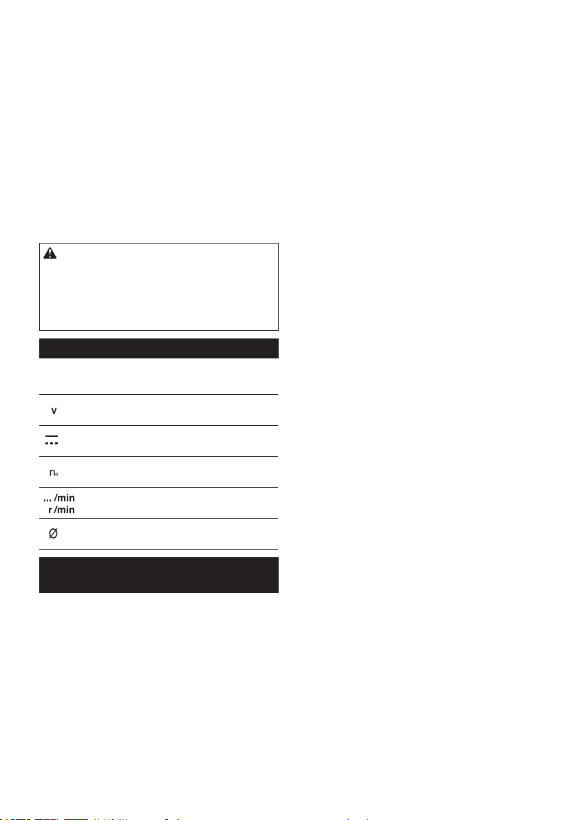
29 ESPAÑOL
12. Mantenga el disco alado y limpio.Lacolayla
resina de madera endurecidas en el disco frenan
lasierrayaumentanlasposibilidadesdequese
produzcan retrocesos bruscos. Mantenga limpio
eldiscoquitándoloprimerodelaherramientay
limpiándoloconeliminadorderesinaygoma,
agua caliente o queroseno. Nunca utilice gasolina.
13. Utilice una máscara antipolvo y protección
para los oídos cuando utilice la herramienta.
14. Siempre utilice el disco de la sierra previsto
para el material que va a cortar.
15. Utilice únicamente los discos de la sierra mar-
cados con una velocidad igual o mayor a la
velocidad marcada en la herramienta.
16.
Coloque la herramienta y las piezas sobre una super-
cie plana y estable. De lo contrario, la herramienta o
laspiezaspodríancaerseyocasionarunalesión.
GUARDE ESTAS INSTRUCCIONES.
ADVERTENCIA: NO DEJE que la comodidad
o familiaridad con el producto (a base de utilizarlo
repetidamente) sustituya la estricta observancia
de las normas de seguridad para dicho producto.
El MAL USO o el no seguir las normas de seguri-
dad establecidas en este manual de instrucciones
puede ocasionar lesiones personales graves.
Símbolos
Acontinuaciónsemuestranlossímbolosutilizados
para la herramienta.
volts o voltios
corriente directa o continua
velocidad sin carga
revoluciones o alternaciones por minuto,
frecuencia de rotación
diámetro
Instrucciones importantes de
seguridad para el cartucho de batería
1. Antes de utilizar el cartucho de batería, lea
todas las instrucciones e indicaciones de
precaución en el (1) el cargador de batería, (2)
la batería, y (3) el producto con el que se utiliza
la batería.
2. No desarme ni modique el cartucho de bate-
ría.Podríaocurrirunincendio,calorexcesivoo
una explosión.
3. Si el tiempo de operación se ha acortado en
exceso, deje de operar de inmediato. Podría
correrse el riesgo de sobrecalentamiento,
posibles quemaduras e incluso explosión.
4. En caso de que ingresen electrolitos en sus
ojos, enjuáguelos bien con agua limpia y con-
sulte de inmediato a un médico. Esto podría
ocasionar pérdida de visión.
5. Evite cortocircuitar el cartucho de batería:
(1) No toque las terminales con ningún mate-
rial conductor.
(2) Evite guardar el cartucho de batería en un
cajón junto con otros objetos metálicos,
tales como clavos, monedas, etc.
(3) No exponga el cartucho de batería al
agua o la lluvia.
Un cortocircuito en la batería puede causar
un ujo grande de corriente, sobrecalenta-
miento, posibles quemaduras e incluso una
descompostura.
6.
No guarde ni utilice la herramienta y el cartucho
de batería en lugares donde la temperatura
pueda alcanzar o exceder los 50 °C (122 °F).
7. Nunca incinere el cartucho de batería incluso
en el caso de que esté dañado seriamente o
ya no sirva en absoluto. El cartucho de batería
puede explotar si se tira al fuego.
8. No clave, corte, aplaste, lance o deje caer el
cartucho de batería, ni golpee un objeto sólido
contra el cartucho de batería. Dicha acción
podríaresultarenunincendio,calorexcesivooen
una explosión.
9. No use una batería dañada.
10.
Las baterías de ión de litio están sujetas a los requisi-
tos reglamentarios en materia de bienes peligrosos.
Paraeltrasportecomercial,porej.,mediante
terceros o agentes de transporte, se deben tomar
en cuenta los requisitos especiales relativos al
empaqueyeletiquetado.
Paraefectuarlospreparativosdelartículoquese
va a enviar, se requiere consultar a un experto en
materiales peligrosos. Si es posible, consulte ade-
más otras regulaciones nacionales más detalladas.
Pegue o cubra con cinta adhesiva los contactos
abiertosyempaquelabateríademaneraqueésta
no pueda moverse dentro del paquete.
11. Para deshacerse del cartucho de batería,
sáquelo de la herramienta y deséchelo en un
lugar seguro. Siga las regulaciones locales
relacionadas al desecho de las baterías.
12.
Utilice las baterías únicamente con los produc-
tos especicados por Makita.Instalarlasbaterías
en productos que no cumplan con los requisitos
podríaocasionarunincendio,uncalentamiento
excesivo, una explosión o una fuga de electrolito.
13.
Si no se utiliza la herramienta por un período
largo, debe extraerse la batería de la herramienta.
14. El cartucho de batería podría absorber calor
durante y después de su uso, lo que ocasiona-
ría quemaduras o quemaduras a baja tempe-
ratura. Tenga cuidado con la manipulación de
los cartuchos de batería que estén calientes.
15. No toque el terminal de la herramienta inme-
diatamente después de su uso, ya que el
mismo podría estar lo sucientemente caliente
como para provocarle quemaduras.
16. No permita que las rebabas, el polvo o la tierra
queden atrapados en los terminales, oricios
y ranuras del cartucho de batería.Podríapro-
vocarcalentamiento,incendio,explosiónymal
funcionamiento de la herramienta o del cartucho
debatería,loqueresultaríaenquemaduraso
lesiones personales.

30 ESPAÑOL
17. No utilice el cartucho de batería cerca de
cables eléctricos de alto voltaje, a menos que
la herramienta sea compatible con el uso cer-
cano a estos cables eléctricos de alto voltaje.
Estopodríaocasionarunaaveríaodescompos-
turadelaherramientaodelcartuchodebatería.
18. Mantenga la batería alejada de los niños.
GUARDE ESTAS INSTRUCCIONES.
PRECAUCIÓN: Utilice únicamente baterías
originales de Makita.Elusodebateríasnoorigina-
lesdeMakita,odebateríasalteradas,puedeocasio-
narquelasbateríasexplotencausandounincendio,
lesionespersonalesydaños.Asimismo,estoinva-
lidarálagarantíadeMakitaparalaherramientayel
cargador Makita.
Consejos para alargar al máximo
la vida útil de la batería
1. Cargue el cartucho de batería antes de que
se descargue completamente. Pare siem-
pre la operación y cargue el cartucho de
batería cuando note menos potencia en la
herramienta.
2. No cargue nunca un cartucho de batería que
esté completamente cargado. La sobrecarga
acortará la vida de servicio de la batería.
3. Cargue el cartucho de batería a una tempera-
tura ambiente de 10 °C - 40 °C (50 °F - 104 °F).
Si un cartucho de batería está caliente, déjelo
enfriar antes de cargarlo.
4. Cuando no utilice el cartucho de batería,
sáquelo de la herramienta o del cargador.
5. Cargue el cartucho de batería si no va a utili-
zarlo durante un período prolongado (más de
seis meses).
Instrucciones importantes de
seguridad para la unidad inalámbrica
1. No desarme ni modique la unidad
inalámbrica.
2. Mantenga la unidad inalámbrica alejada de
los niños pequeños. En caso de ingerirla
accidentalmente, solicite atención médica de
inmediato.
3. Utilice la unidad inalámbrica solamente con
herramientas de Makita.
4. No exponga la unidad inalámbrica a la lluvia ni
a condiciones de humedad.
5. No utilice la unidad inalámbrica en lugares
donde la temperatura exceda los 50 °C (122
°F).
6. No utilice la unidad inalámbrica en lugares
donde haya instrumentos médicos tales como
marcapasos cerca.
7. No utilice la unidad inalámbrica en lugares
donde haya dispositivos automáticos cerca.
Siseutiliza,losdispositivosautomáticospodrían
causaralgunaaveríaoerror.
8. No opere la unidad inalámbrica en lugares con
alta temperatura o donde pueda generarse
electricidad estática o ruido eléctrico.
9. La unidad inalámbrica puede producir campos
electromagnéticos (CEM), sin embargo éstos
no son dañinos para el usuario.
10. La unidad inalámbrica es un instrumento de
precisión. Tenga cuidado de no dejar caer ni
golpear la unidad inalámbrica.
11. Evite tocar la terminal de la unidad inalámbrica
con las manos descubiertas o con materiales
metálicos.
12. Retire siempre la batería del producto al insta-
lar en él la unidad inalámbrica.
13. Cuando abra la tapa de la ranura, evite el lugar
donde el polvo y el agua puedan introducirse
en la ranura. Mantenga siempre la entrada de
la ranura limpia.
14. Inserte siempre la unidad inalámbrica en la
dirección correcta.
15. No oprima el botón de activación inalámbrica
en la unidad inalámbrica demasiado fuerte, ni
lo haga con ningún objeto que tenga un borde
loso.
16. Cierre siempre la tapa de la ranura durante la
operación.
17. No retire la unidad inalámbrica de la ranura
mientras se esté suministrando energía a la
herramienta.Elhacerlopodríacausarunaavería
de la unidad inalámbrica.
18. No retire la etiqueta en la unidad inalámbrica.
19. No coloque ninguna etiqueta en la unidad
inalámbrica.
20. No deje la unidad inalámbrica en un lugar
donde pueda generarse electricidad estática o
ruido eléctrico.
21. No deje la unidad inalámbrica en un lugar
sujeto a temperaturas altas, tal como un vehí-
culo estacionado bajo el sol.
22. No deje la unidad inalámbrica en un lugar
donde haya polvo o suciedad ni en un lugar
donde pueda generarse gas corrosivo.
23. Los cambios repentinos de temperatura
podrían humedecer la unidad inalámbrica. No
utilice la unidad inalámbrica hasta que la con-
densación se haya secado por completo.
24. Cuando vaya a limpiar la unidad inalámbrica,
hágalo cuidadosamente usando un paño
suave seco. No utilice bencina, disolvente,
grasa conductora o sustancias similares.
25. Cuando vaya a almacenar la unidad inalám-
brica, guárdela en el estuche suministrado o
en un contenedor libre de electricidad estática.
26. No inserte ningún otro dispositivo que no sea
la unidad inalámbrica de Makita en la ranura de
la herramienta.
27. No utilice la herramienta si la tapa de la ranura
está dañada. La entrada de agua, polvo o sucie-
dadenlaranurapodríacausarunaavería.
28. No jale ni tuerza la tapa de la ranura más de
lo necesario. Vuelva a colocar la tapa si ésta se
sale de la herramienta.
29. Reemplace la tapa de la ranura si llega a per-
derse o dañarse.
GUARDE ESTAS INSTRUCCIONES.
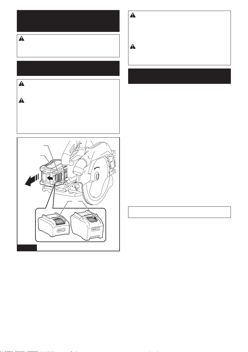
31 ESPAÑOL
DESCRIPCIÓN DEL
FUNCIONAMIENTO
PRECAUCIÓN: Asegúrese siempre de que la
herramienta esté apagada y el cartucho de batería
haya sido extraído antes de realizar cualquier
ajuste o comprobación en la herramienta.
Instalación o extracción del
cartucho de batería
PRECAUCIÓN: Apague siempre la herra-
mienta antes de colocar o quitar el cartucho de
batería.
PRECAUCIÓN: Sujete la herramienta y el car-
tucho de la batería con rmeza al colocar o quitar
el cartucho de batería.Sinosesujetaconrmezala
herramientayelcartuchodebatería,puedeocasio-
nar que se resbalen de sus manos causando daños
alaherramientayalcartuchodebatería,asícomo
lesiones a la persona.
3
2
1
Fig.7
►1.Indicadorrojo2. Botón 3.Cartuchodebatería
Paraquitarelcartuchodebatería,deslícelodelaherra-
mienta mientras desliza el botón sobre la parte delan-
tera del cartucho.
Parainstalarelcartuchodebatería,alineelalengüeta
sobreelcartuchodebateríaconlaranuraenlacarcasa
ydeslícelahastasulugar.Insérteloporcompletohasta
quesejeensulugarconunpequeñoclic.Sipuede
verelindicadorrojocomosemuestraenlailustración,
este no ha quedado asegurado por completo.
PRECAUCIÓN: Introduzca siempre com-
pletamente el cartucho de batería hasta que
el indicador rojo no pueda verse.Sino,podría
accidentalmentesalirsedelaherramientaycaeral
suelo causando una lesión a usted o alguien a su
alrededor.
PRECAUCIÓN: No instale el cartucho de
batería a la fuerza. Si el cartucho no se desliza al
interior fácilmente, se debe a que no está siendo
insertado correctamente.
Sistema de protección para la
herramienta/batería
La herramienta está equipada con un sistema de pro-
tecciónparalaherramienta/batería.Estesistemacorta
enformaautomáticaelsuministrodeenergíaalmotor
paraprolongarlavidaútildelaherramientaylabatería.
La herramienta se detendrá automáticamente durante
laoperaciónsilaherramientaolabateríasesometena
una de las siguientes condiciones. En algunas condicio-
nes, los indicadores pueden encenderse.
Protección contra sobrecarga
Cuandolaherramienta/bateríaseanutilizadasde
una manera que cause que consuman una cantidad
inusualmente alta de corriente, la herramienta se
detendrá automáticamente. En este caso, apague la
herramientaydetengalaaplicaciónquecausóquela
herramienta se sobrecargara. Luego encienda la herra-
mienta para volver a arrancarla.
Protección contra sobrecalentamiento
Cuandolaherramienta/bateríasesobrecalienten,la
herramienta se detendrá automáticamente. En este
caso,permitaquelaherramientaseenfríeantesde
volver a encenderla.
NOTA: Cuando la herramienta se sobrecaliente, la
lámpara parpadeará.
Protección contra sobredescarga
Cuandolacapacidaddelabateríasereduce,laherra-
mienta se detiene automáticamente. Si el producto no fun-
ciona incluso cuando los interruptores están siendo opera-
dos,retirelasbateríasdelaherramientaycárguelas.
Protección contra otras causas
El sistema de protección también está diseñado para
otrascausasquepodríandañarlaherramienta,yper-
mite que la herramienta se detenga automáticamente.
Siga todos los pasos a continuación para eliminar las
causascuandolaherramientasehayadetenidotempo-
ralmenteosehayadetenidoduranteelfuncionamiento.
1. Apaguelaherramienta,yluegoenciéndalanueva-
mente para reiniciarla.
2. Carguela(s)batería(s)oreemplácela(s)con
batería(s)recargada(s).
3.
Dejequelaherramientayla(s)batería(s)seenfríen.
Sinohayningunamejoraalrestaurarelsistemade
protección,comuníqueseconsucentrolocaldeservi-
cio Makita.
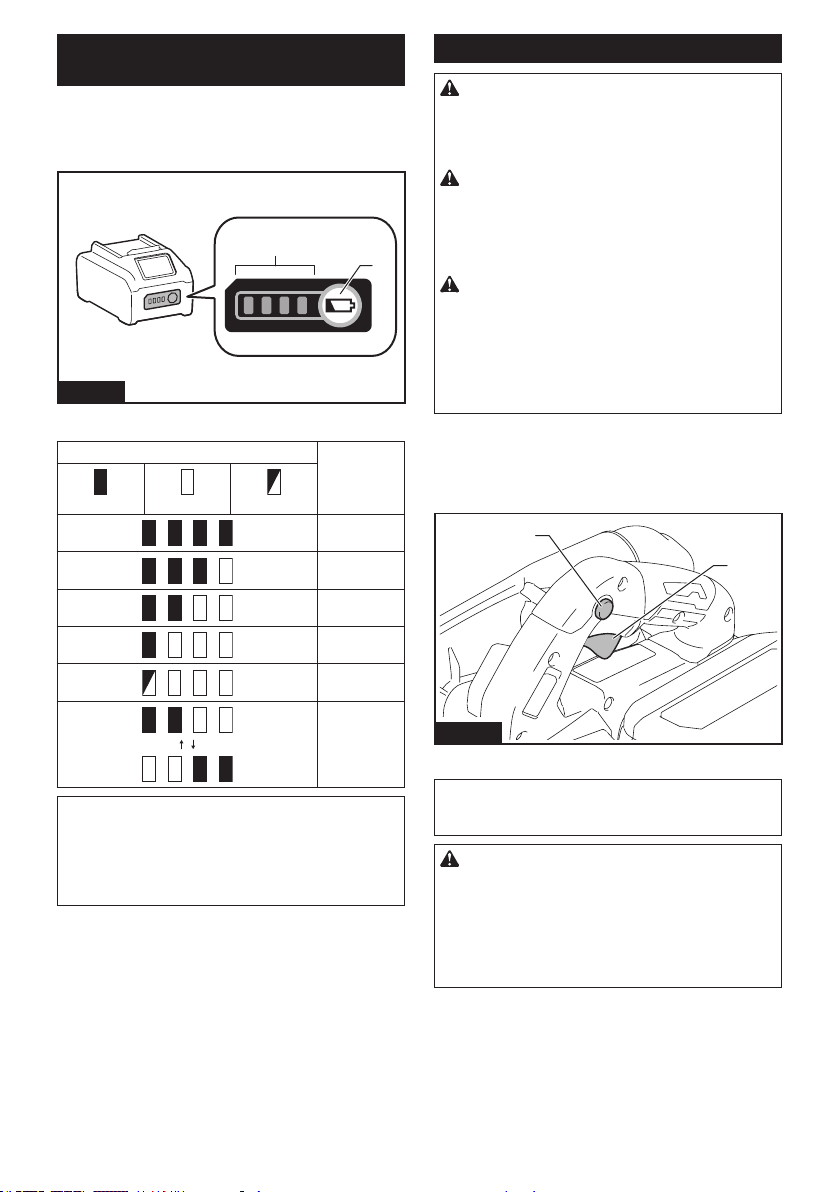
32 ESPAÑOL
Indicación de la capacidad restante
de la batería
Oprimaelbotóndevericaciónenelcartuchodela
bateríaparaqueindiquelacapacidadrestantedela
batería.Laslucesindicadorasseiluminaránporalgu-
nos segundos.
1
2
Fig.8
►1. Luces indicadoras 2.Botóndevericación
Luces indicadoras Capacidad
restante
Iluminadas Apagadas Parpadeando
75% a 100%
50% a 75%
25% a 50%
0% a 25%
Cargar la
batería.
Labatería
pudo haber
funcionado
mal.
NOTA:Dependiendodelascondicionesdeusoy
la temperatura ambiente, la indicación podrá diferir
ligeramente de la capacidad real.
NOTA: La primera luz indicadora (extrema izquierda)
parpadeará cuando el sistema de protección de
bateríaestéenfuncionamiento.
Accionamiento del interruptor
ADVERTENCIA: Antes de insertar el car-
tucho de batería en la herramienta, compruebe
siempre y cerciórese de que el gatillo interruptor
se acciona debidamente y que vuelve a la posi-
ción “OFF” (apagado) cuando lo suelta.
ADVERTENCIA: NUNCA inhabilite el botón
de desbloqueo manteniéndolo presionado con
cinta adhesiva o mediante otro método. El uso
de un interruptor con un botón de desbloqueo inha-
bilitadopuedeocasionarunaoperaciónaccidentaly
lesiones personales graves.
ADVERTENCIA: NUNCA use la herramienta
si se activa simplemente al jalar el gatillo inte-
rruptor sin que haya presionado el botón de
desbloqueo. El uso de un interruptor que requiere
reparación puede ocasionar una operación accidental
ylesionespersonalesgraves.Llevelaherramienta
a un centro de servicio Makita para las reparaciones
apropiadas ANTES de continuar su uso.
El botón de desbloqueo es suministrado para evitar
jalaraccidentalmenteelgatillointerruptor.Paraarran-
carlaherramienta,presioneelbotóndedesbloqueoy
jaleelgatillointerruptor.Paradetenerla,suelteelgatillo
interruptor.
2
1
Fig.9
►1. Gatillo interruptor 2. Botón de desbloqueo
AVISO: No jale fuertemente el gatillo interruptor
sin presionar el botón de desbloqueo.Estopodría
dañar el interruptor.
PRECAUCIÓN: La herramienta comenzará
a frenar la rotación del disco de la sierra circular
inmediatamente después de haber soltado el
gatillo interruptor. Sostenga la herramienta rme-
mente para responder a la reacción del freno al
soltar el gatillo interruptor. Una reacción repentina
podríahacercaerlaherramientadesumanoyoca-
sionar una lesión personal.
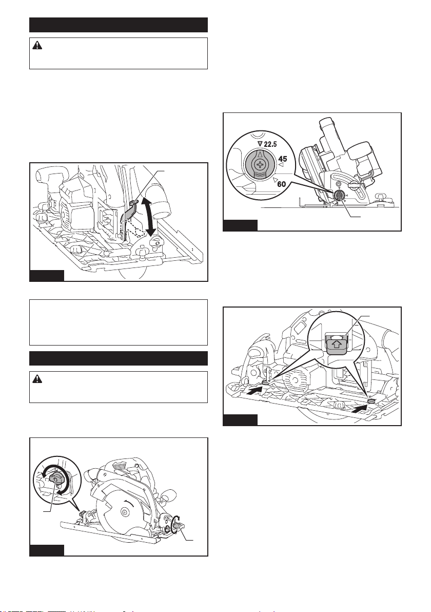
33 ESPAÑOL
Ajuste de la profundidad de corte
PRECAUCIÓN: Después de ajustar la pro-
fundidad de corte, siempre apriete la palanca
rmemente.
Aojelapalancaenlaguíadeprofundidadymuevala
basehaciaarribaohaciaabajo.Enlaprofundidadde
cortedeseada,jelabaseapretandolapalanca.
Paraobtenercortesmáslimpiosyseguros,ajustela
profundidad de corte de forma que no sobresalga más
deundientedeldiscopordebajodelapiezadetrabajo.
Elusodeunaprofundidaddecorteadecuadaayudaa
reducir la posibilidad de que se produzca un peligroso
RETROCESO BRUSCO que pueda ocasionar lesiones
personales.
1
Fig.10
►1. Palanca
AVISO: Si la base no se desliza hacia arriba o hacia
abajoconsuavidad,esposiblequelaguíadepro-
fundidadsehayainclinado.Enestecaso,ajustela
guíadeprofundidad(consultelasecciónsobrecómo
ajustarlaguíadeprofundidad).
Corte en bisel
PRECAUCIÓN: Después de ajustar el ángulo
de bisel, apriete siempre los tornillos de jación
con rmeza.
Aojelostornillosdejación.Ajusteelángulodeseado
inclinandosegúncorresponda,despuésaprietelos
tornillosdejaciónrmemente.
1
1
Fig.11
►1.Tornillodejación
Tope de seguridad
Eltopedeseguridadsirvedeayudaparaajustarrápi-
damente el ángulo designado. Gire el tope de seguri-
daddemaneraquelaechasobreésteapuntehaciael
ángulo de bisel deseado (alrededor de 22,5°/45°/60°).
Aojelapalancayluegoinclinelabasedelaherra-
mienta hasta que se detenga. La base de la herra-
mientasedetendráenlaposicióndelánguloquehaya
ajustadoconeltopedeseguridad.Aprietelapalanca
con la base de la herramienta en esta posición.
1
Fig.12
►1. Tope de seguridad
Corte en bisel a -1°
Pararealizaruncorteenbisela-1°,aojelostornillos
dejaciónypresionelaspalancasendireccióndela
echaquesemuestraenlailustración.Luegoajusteel
ángulodebisela-1°yaprietelostornillosdejación.
1
Fig.13
►1. Palanca
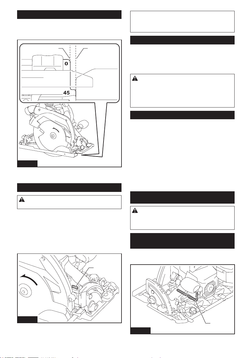
34 ESPAÑOL
Guía visual
Para cortes rectos, alinee la posición de 0° en la parte
delanteradelabaseconsulíneadecorte.Paracortes
en bisel a 45°, alinee la posición de 45° con la misma.
1 2
Fig.14
►1.Líneadecorte(posiciónde0°)2.Líneadecorte
(posición de 45°)
Encendido de la lámpara
PRECAUCIÓN: No mire a la luz ni vea a la
fuente de luz directamente.
Para encender la lámpara sin poner en marcha la
herramienta,jaleelgatillointerruptorsinoprimirel
botón de desbloqueo.
Para encender la lámpara con la herramienta puesta
enmarcha,presioneymantengaoprimidoelbotónde
desbloqueoyjaleelgatillointerruptor.
La lámpara se apagará 10 segundos después tras
haber soltado el gatillo interruptor.
1
Fig.15
►1. Lámpara
NOTA: Utilice un paño seco para quitar la suciedad
delalentedelalámpara.Tengacuidadodenorayar
lalentedelalámparayaquelailuminaciónpodría
disminuir.
Freno eléctrico
La herramienta está equipada con un freno eléctrico
para el disco. Si la herramienta falla constantemente en
la detención rápida del disco de la sierra circular tras
soltar la palanca del interruptor, lleve la herramienta a
mantenimiento a un centro de servicio Makita.
PRECAUCIÓN: El sistema de frenado
del disco no es un sustituto del protector del
disco. NUNCA UTILICE LA HERRAMIENTA SI
EL PROTECTOR DEL DISCO NO FUNCIONA. EL
HACERLO PODRÍA OCASIONAR UNA LESIÓN
PERSONAL.
Función eléctrica
Las herramientas equipadas con funciones electrónicas
sonfácilesdeoperargraciasala(s)característica(s)a
continuación.
Función de arranque suave
Permite el arranque suave gracias a que reduce el
impacto de encendido.
Control de velocidad constante
El control de velocidad electrónico consiste en obtener
una velocidad constante. Permite lograr un buen aca-
bado debido a que la velocidad de rotación se mantiene
constanteaunbajolacondicióndecarga.
MONTAJE
PRECAUCIÓN: Asegúrese siempre de que la
herramienta esté apagada y el cartucho de batería
haya sido extraído antes de realizar cualquier
trabajo en la misma.
Almacenamiento de la llave Allen
(hexagonal)
Cuando no la utilice, guarde la llave hexagonal como se
muestraenlaguraparaevitarquesepierda.
1
Fig.16
►1. Llave Allen (hexagonal)
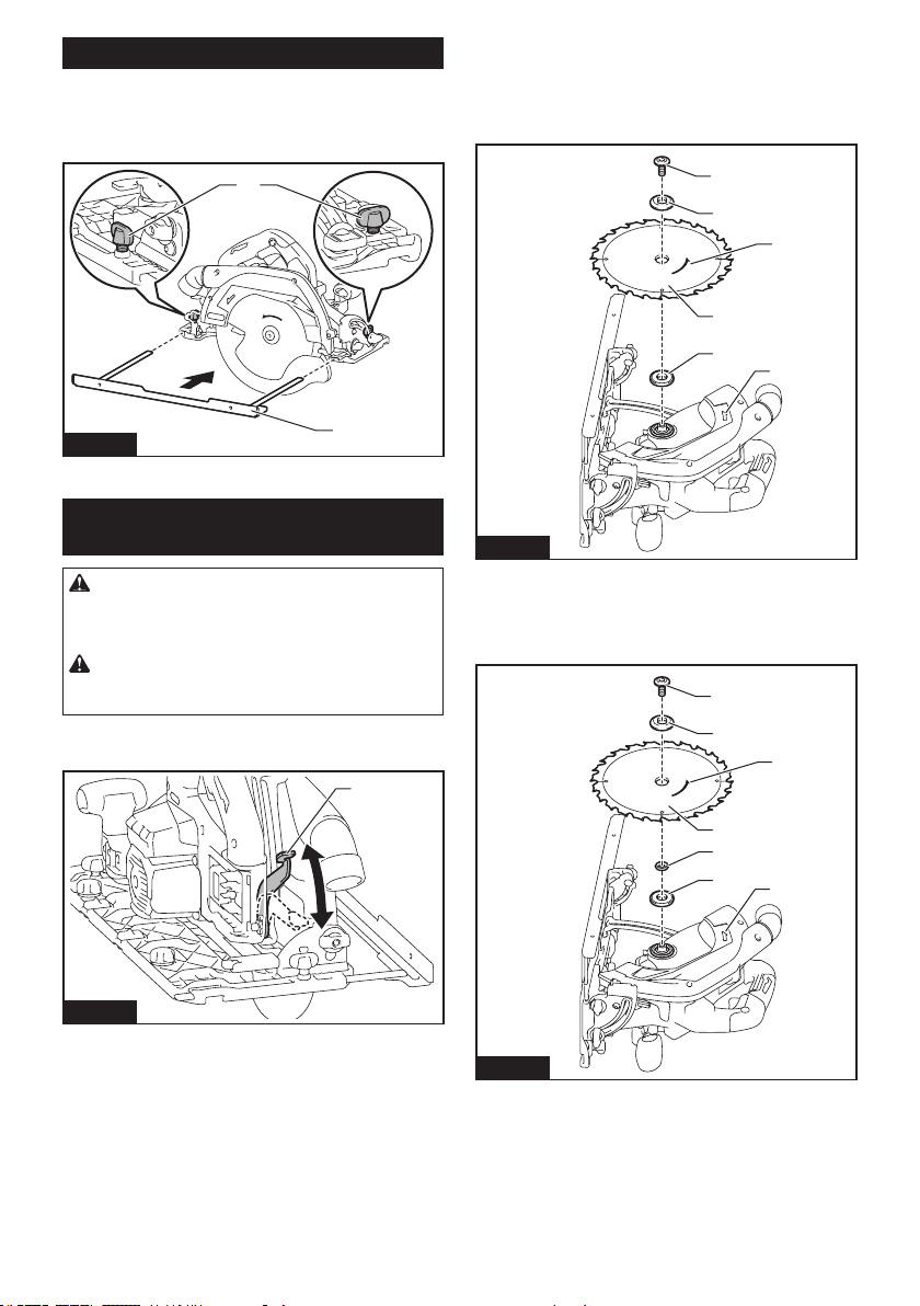
35 ESPAÑOL
Instalación de la base inferior
Instalelabaseinferioryaprietelostornillodejación
rmemente,talcomosemuestraenlagura.
Siempre utilice la herramienta con la base inferior, a
menosqueutiliceelcarrilguía.
1
2
Fig.17
►1.Tornillodejación2. Base inferior
Instalación o desinstalación del
disco de la sierra circular
PRECAUCIÓN: Asegúrese de que el disco
de la sierra circular esté instalado con los dientes
orientados hacia arriba en la parte delantera de la
herramienta.
PRECAUCIÓN: Utilice solamente la llave
Makita para instalar o extraer el disco de la sierra
circular.
1. Aojelapalancaenlaguíadeprofundidady
muevalabasehaciaabajo.
1
Fig.18
►1. Palanca
2. Instalelabridainterior,elanillo(especícoparael
país),eldiscodelasierracircular,labridaexterioryel
perno hexagonal. En este momento, alinee la dirección
delaechadeldiscoconlaechadelaherramienta.
Para la herramienta sin anillo
1
2
4
5
6
3
Fig.19
►1. Perno hexagonal 2. Brida exterior 3. Disco de la
sierra circular 4. Brida interior 5. Flecha en el disco
de la sierra circular 6. Flecha en la herramienta
Para la herramienta con anillo
1
2
4
5
3
6
7
Fig.20
►1. Perno hexagonal 2. Brida exterior 3. Disco de
la sierra circular 4. Anillo 5. Brida interior 6. Flecha
en el disco de la sierra circular 7. Flecha en la
herramienta
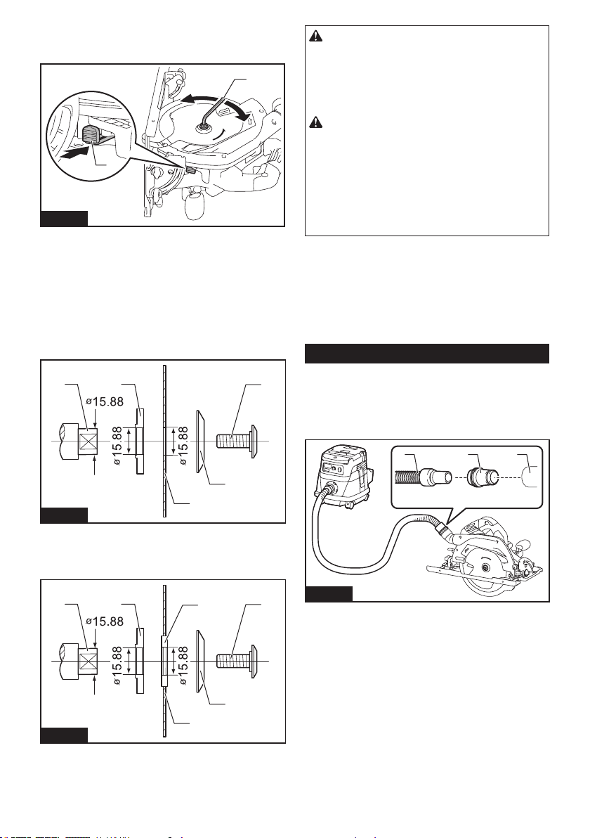
36 ESPAÑOL
3. Presioneelbloqueodelejeporcompletodeforma
queeldiscodelasierracircularnopuedagiraryusela
llave hexagonal para apretar el perno hexagonal.
1
2
3
4
Fig.21
►1.Bloqueodeleje2. Llave hexagonal 3.Aojar
4. Apretar
Para extraer el disco de la sierra circular, siga el proce-
dimiento de instalación en orden inverso.
Instale la brida interior con su lado ahuecado orientado
haciaafuerasobreelejedemontajeyluegocoloqueel
disco de la sierra (con el anillo puesto si es necesario),
labridaexterioryelpernohexagonal.
Para la herramienta sin anillo
12
3
4
5
Fig.22
►1.Ejedemontaje2. Brida interior 3. Disco de la
sierra circular 4. Brida exterior 5. Perno hexagonal
Para la herramienta con anillo
12
3
4
5
6
Fig.23
►1.Ejedemontaje2. Brida interior 3. Disco de la
sierra circular 4. Brida exterior 5. Perno hexagonal
6. Anillo
ADVERTENCIA: ASEGÚRESE DE APRETAR
FIRMEMENTE EL PERNO HEXAGONAL EN EL
SENTIDO DE LAS MANECILLAS DEL RELOJ.
Asimismo, tenga cuidado de no apretar el perno
con demasiada fuerza. Si su mano llega a resba-
larse de la llave hexagonal podría ocasionarle una
lesión.
ADVERTENCIA: Si se requiere un anillo para
montar el disco sobre el eje, asegúrese siempre
de instalar el anillo correcto para el oricio del
eje del disco que desea utilizar entre las bridas
interior y exterior. El uso de un anillo incorrecto
paraeloriciodelejepuedeocasionarunmontaje
inadecuado del disco provocando que éste se mueva
yvibreexcesivamente,pudiendocausarasuvezla
pérdidadecontroldurantelaoperaciónylesiones
personales graves.
Limpieza del protector del disco
Alcambiareldiscodelasierracircular,asegúresede
limpiartambiénelaserrínacumuladoenlosprotectores
superior e inferior del disco, tal como se indica en la
sección de Mantenimiento. Sin embargo, esta tarea no
sustituyelanecesidadderevisarlaoperacióndelpro-
tector inferior antes de cada uso.
Conexión de una aspiradora
Accesorio opcional
Cuando desee realizar una operación de corte limpia,
conecte una aspiradora Makita a su herramienta.
Conecte la manguera de la aspiradora a la boquilla
para polvo usando los manguitos delanteros 24.
1 2 3
Fig.24
►1. Manguera de la aspiradora 2. Manguitos delante-
ros 24 3. Boquilla para polvo
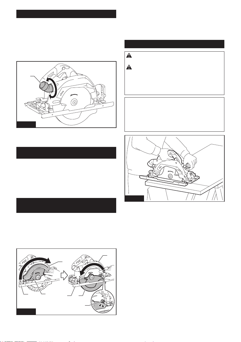
37 ESPAÑOL
Ajuste del ángulo de la boquilla para polvo
Elángulodelaboquillaparapolvosepuedeajustaralgirarla.
Cuando opere la herramienta sin conectar una aspi-
radora,pongalaboquillaparapolvohaciaabajopara
evitarqueeloperadorquedeexpuestoalaserrín.
Cuandooperelaherramientayconectaunaaspiradora,
ponga la boquilla para polvo hacia arriba para evitar
que la manguera de la aspiradora quede atrapada en la
piezadetrabajooenelcarrilguía.
1
Fig.25
►1. Boquilla para polvo
OPERACIÓN
Esta herramienta está diseñada para cortar productos
demaderaúnicamente.
Consulte nuestro sitio web o póngase en contacto con su distribui-
dor local de Makita para información sobre los discos de sierra cir-
culares correctos para emplearse con el material que se va a cortar.
No utilice la herramienta sin la base inferior, salvo
cuandoutiliceelcarrilguía.
Vericación de la función del
protector del disco
Retireelcartuchodebatería.
Fijeelángulodebisela0°yluegoretraigamanual-
menteelprotectorinferiorhastaelnalysuéltelo.El
protector inferior funcionará adecuadamente si:
—
seretraeporencimadelabasesinningúnobstáculo;y
—
regresaautomáticamenteyhacecontactoconeltope.
1
2
1
5
6
3
4
2
3
Fig.26
►1. Protector superior 2. Protector inferior 3. Base
4. Tope 5. Abrir 6. Cerrar
Si el protector inferior no funciona adecuadamente,
veriquesiseacumulóaserríndentrodelprotector
superior e inferior. Si el protector inferior no está fun-
cionando adecuadamente, incluso después de retirar
el polvo, lleve su herramienta a un centro de servicio
Makita para que le den servicio.
Operación de corte
PRECAUCIÓN: Utilice una máscara contra
polvo cuando realice la operación de corte.
PRECAUCIÓN: Asegúrese de mover la
herramienta hacia adelante en línea recta y sua-
vemente. El forzar o torcer la herramienta producirá
unsobrecalentamientodelmotoryunpeligroso
retroceso brusco, posiblemente causando lesiones
graves.
NOTA:Cuandoelcartuchodebateríaestáfrío,la
herramienta puede no funcionar a su capacidad com-
pleta.Enesemomentouselaherramienta,porejem-
plo,paracortesligerosdurantealgúntiempohasta
queelcartuchodebateríasecalientehastaalcanzar
la temperatura ambiente. De este modo, la herra-
mienta podrá funcionar a su capacidad completa.
Fig.27
Sujetermementelaherramienta.Laherramientaestá
provistadeempuñaduradelanteraymangotrasero.
Utiliceambosparasujetardeformaóptimalaherra-
mienta.Siambasmanosestánsujetandolasierra,éstas
no podrán ser cortadas por el disco de la sierra circular.
Coloquelabasesobrelapiezadetrabajoacortarsin
que el disco de la sierra circular haga contacto alguno.
Luegoenciendalaherramientayespereaqueeldisco
de la sierra circular alcance su velocidad completa. Ahora
simplemente mueva la herramienta hacia adelante sobre
lasuperciedelapiezadetrabajo,manteniéndolaplana
yavanzandosuavementehastacompletarelcorte.
Paraobtenercorteslimpios,mantengalalíneadecorte
rectaylavelocidaddeavanceuniforme.Sisedesvía
delalíneadecorteprevista,nointentegirarniforzar
laherramientaparahacerlavolveralalíneadecorte.
Estaacciónpodríaatorareldiscodelasierracircular
yocasionarunpeligrosoretrocesobruscoyposibles
lesiones graves. Suelte el interruptor, espere hasta
queeldiscodelasierracircularsedetengaydespués
retire la herramienta. Vuelva a alinear la herramienta en
unanuevalíneadecorteycomienceelcorteotravez.
Hayqueevitarposturasenlasqueeloperadorquede
expuestoalasastillasyelaserrínexpulsadosdela
sierra.Useprotecciónparalosojosparapoderevitar
las lesiones.
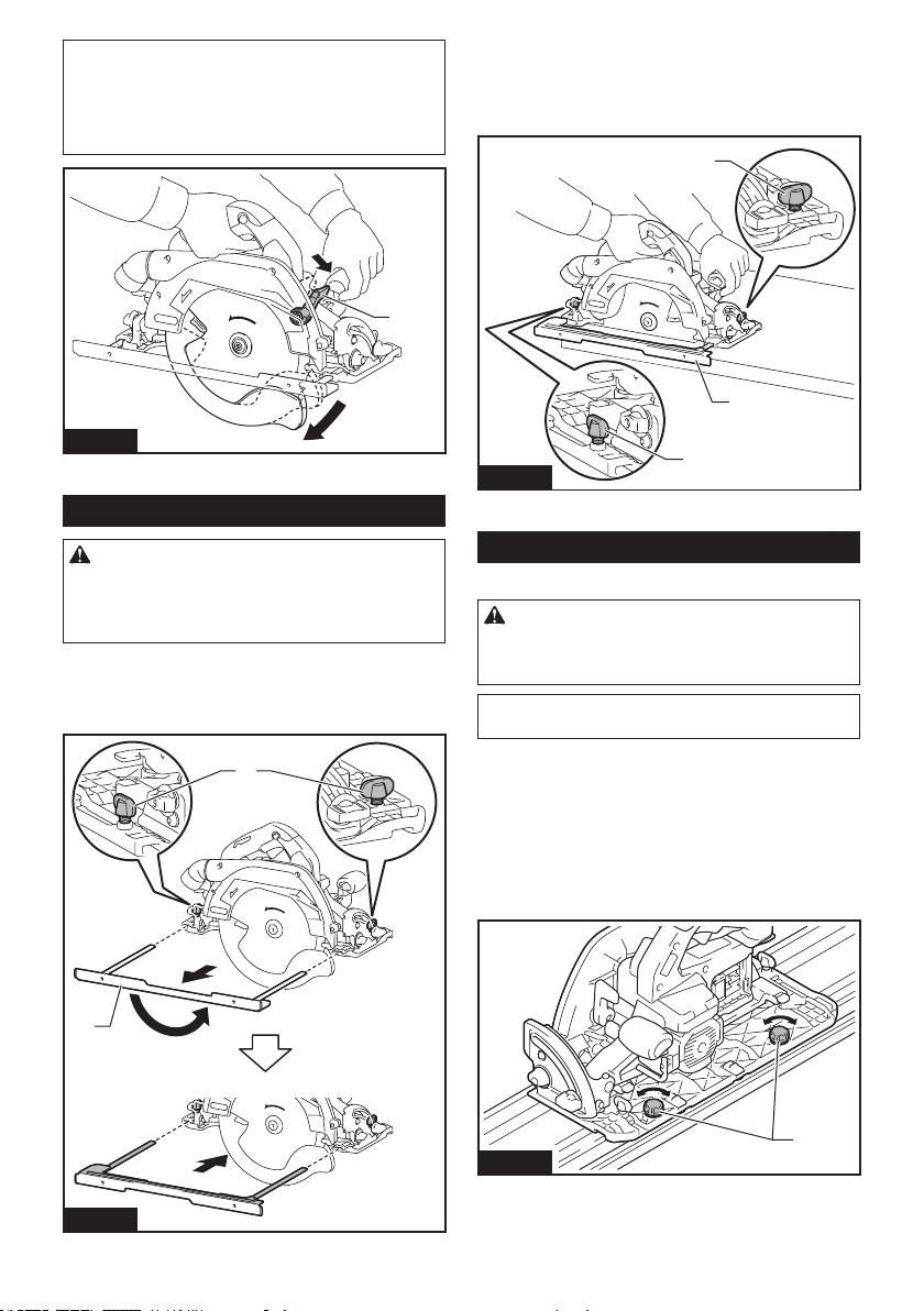
38 ESPAÑOL
NOTA: A la hora de realizar cortes de ingleta, etc., a
veces la protección inferior no se mueve con facili-
dad. En ese momento, utilice la palanca retráctil para
levantar la protección inferior e iniciar el corte. No
bienlahojaingreseenelmaterial,liberelapalanca
retráctil.
1
Fig.28
►1. Palanca de retracción
Base inferior (regla guía)
PRECAUCIÓN: Asegúrese de que la base
inferior (regla guía) esté rmemente instalada
en la posición correcta antes del uso. Un acopla-
mientoincorrectopodríaocasionarretrocesosbrus-
cos peligrosos.
Medianteelusodelabaseinferiorcomoreglaguía,usted
puederealizarcortesrectosconextremaprecisión.Aoje
lostornillosdejación,deslicelabaseinferiorhaciaafuera
delaherramientayluegoinsérteladecabeza.
1
2
Fig.29
►1.Tornillodejación2. Base inferior
Simplementedeslicelaguíadelabaseinferiorde
maneraquequedeajustadacontraelladodelapieza
detrabajoyfíjelaensuposiciónusandolostornillosde
jación.Conellotambiénsepuedenhacercortesrepe-
tidos de anchura uniforme.
1
2
1
Fig.30
►1.Tornillodejación2. Base inferior
Carril guía
Accesorio opcional
PRECAUCIÓN: Asegúrese siempre de que la
herramienta esté apagada y el cartucho de batería
haya sido extraído antes de realizar cualquier
trabajo en la misma.
AVISO: Retire la base inferior cuando utilice el carril
guía.
Coloque la herramienta en el extremo trasero del carril
guía.Girelosdostornillosdeajustesobrelabasede
laherramientadetalformaqueéstasedeslicesuavey
libremente.Sujetetantolaempuñaduradelanteracomo
elmangotraserodelaherramientarmemente.Instale
elcartuchodebatería.Enciendalaherramientaycorte
el protector contra astillas a lo largo de toda la longitud
con una pasada. El borde del protector contra astillas
ahora corresponde con el borde de corte.
1
Fig.31
►1.Tornillosdeajuste
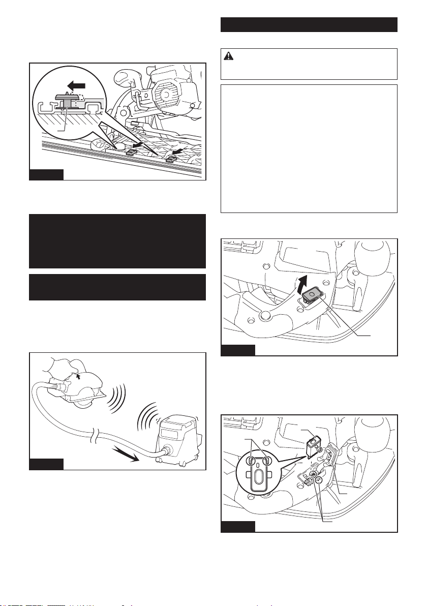
39 ESPAÑOL
Cuandorealicecortesenbiselconelcarrilguía,utilicela
palanca deslizable para evitar que la herramienta se caiga.
Mueva la palanca deslizable sobre la base de la herra-
mientaenladireccióndelaechademaneraque
encajeenlaranuradelcortealrasenelcarrilguía.
1
Fig.32
►1. Palanca deslizable
FUNCIÓN DE
ACTIVACIÓN
INALÁMBRICA
Lo que puede hacer con la función
de activación inalámbrica
La función de activación inalámbrica permite una ope-
raciónlimpiaycómoda.Siconectaalaherramienta
una aspiradora compatible, podrá hacer que ésta
funcione automáticamente al activar el interruptor de la
herramienta.
Fig.33
Para hacer uso de la función de activación inalámbrica,
tenga preparado lo siguiente:
• Una unidad inalámbrica (accesorios opcionales)
• Una aspiradora compatible con la función de
activación inalámbrica
A continuación se presenta la descripción general del
ajustedelafuncióndeactivacióninalámbrica.Consulte
cada sección para ver los procedimientos a detalle.
1. Instalación de la unidad inalámbrica
2. Registro de la herramienta para la aspiradora
3. Inicio de la función de activación inalámbrica
Instalación de la unidad inalámbrica
Accesorio opcional
PRECAUCIÓN: Coloque la herramienta sobre
una supercie plana y estable cuando vaya a
instalar la unidad inalámbrica.
AVISO: Limpie el polvo y la suciedad en la herra-
mienta antes de instalar la unidad inalámbrica.
Elpolvoolasuciedadpodríancausarunaavería
si llegan a introducirse en la ranura de la unidad
inalámbrica.
AVISO: Para evitar una avería a causa de la elec-
tricidad estática, toque un material de descarga
de electricidad estática, tal como una pieza metá-
lica de la herramienta antes de levantar la unidad
inalámbrica.
AVISO: Cuando vaya a instalar la unidad inalám-
brica, asegúrese siempre de que ésta sea inser-
tada en la dirección correcta y que la tapa esté
completamente cerrada.
1. Abra la tapa en la herramienta tal como se mues-
tra en la ilustración.
1
Fig.34
►1. Tapa
2. Insertelaunidadinalámbricaenlaranurayluego
cierre la tapa.
Cuando inserte la unidad inalámbrica, alinee las partes
salientes con las partes cóncavas en la ranura.
1
2
3
4
Fig.35
►1. Unidad inalámbrica 2. Parte saliente 3. Tapa
4. Parte cóncava
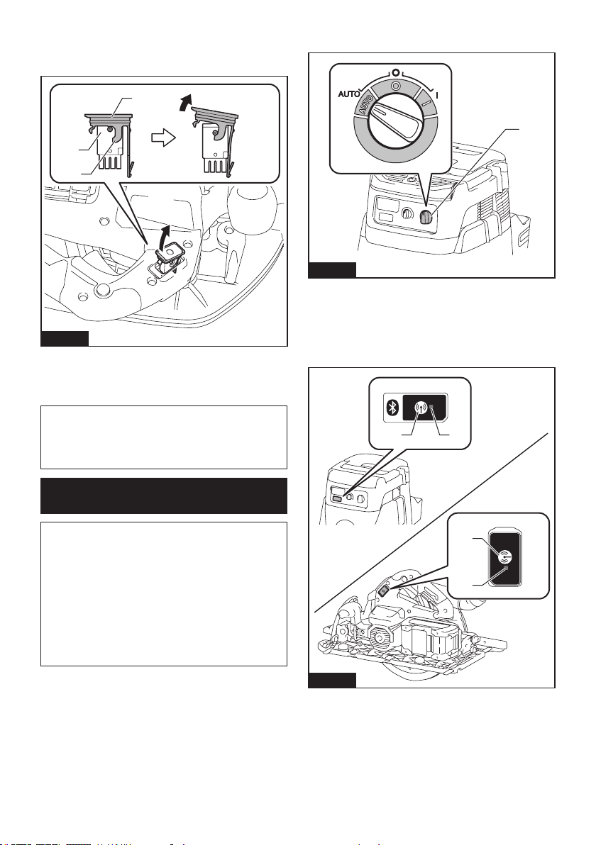
40 ESPAÑOL
Cuando extraiga la unidad inalámbrica, abra la tapa
lentamente. Los ganchos en la parte posterior de la
tapa levantarán la unidad inalámbrica mientras usted
jalahaciaarribalatapa.
1
2
3
Fig.36
►1. Unidad inalámbrica 2. Gancho 3. Tapa
Unavezextraídalaunidadinalámbrica,guárdelaenel
estuche suministrado o en un contenedor libre de elec-
tricidad estática.
AVISO: Use siempre los ganchos en la parte
posterior de la tapa cuando extraiga la unidad
inalámbrica.Silosganchosnosujetanlaunidad
inalámbrica,cierrelatapaporcompletoyvuelvaa
abrirla lentamente.
Registro de la herramienta para la
aspiradora
NOTA: Para el registro de la herramienta, se requiere
una aspiradora Makita compatible con la función de
activación inalámbrica.
NOTA: Termine de instalar la unidad inalámbrica en
la herramienta antes de comenzar con el registro de
la herramienta.
NOTA:Duranteelregistrodelaherramienta,nojale
el gatillo interruptor ni active el interruptor de encen-
dido en la aspiradora.
NOTA: Consulte también el manual de instrucciones
de la aspiradora.
Sideseaactivarlaaspiradorajuntoconelinterruptor
de la herramienta, termine antes con el registro de la
herramienta.
1. Instalelasbateríasenlaaspiradorayenla
herramienta.
2. Ajusteelinterruptordemodoenesperaenlaaspi-
radora en “AUTO”.
1
Fig.37
►1. Interruptor de modo en espera
3. Oprima el botón de activación inalámbrica en la
aspiradora durante 3 segundos hasta que la luz indica-
dora de activación inalámbrica parpadee en verde. Y
luego oprima el botón de activación inalámbrica en la
herramienta de la misma manera.
1 2
1
2
Fig.38
►1. Botón de activación inalámbrica 2. Luz indica-
dora de activación inalámbrica
Silaaspiradoraylaherramientahansidoconectadas
exitosamente, las luces indicadoras de activación ina-
lámbricaseencenderánenverdedurante2segundosy
comenzarán a parpadear en azul.
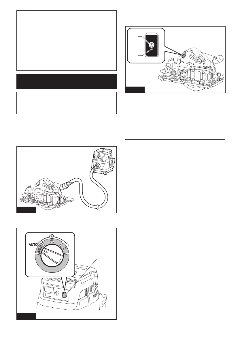
41 ESPAÑOL
NOTA: Las luces indicadoras de activación inalám-
brica terminarán parpadeando en verde después de
un lapso de 20 segundos. Oprima el botón de acti-
vación inalámbrica en la herramienta mientras la luz
indicadora de activación inalámbrica en la aspiradora
esté parpadeando. Si la luz indicadora de activación
inalámbrica no parpadea en verde, oprima el botón
deactivacióninalámbricaduranteunlapsobrevey
vuelva a mantenerlo oprimido.
NOTA: Cuando realice dos o más registros de la
herramienta para una aspiradora, termine el registro
de la herramienta de uno en uno.
Inicio de la función de activación
inalámbrica
NOTA: Termine con el registro de la herramienta para
la aspiradora antes de la activación inalámbrica.
NOTA: Consulte también el manual de instrucciones
de la aspiradora.
Después de registrar una herramienta en la aspiradora,
estaúltimaseactivaráautomáticamentejuntoconel
interruptor de la herramienta.
1. Instale la unidad inalámbrica en la herramienta.
2.
Conecte la manguera de la aspiradora a la herramienta.
Fig.39
3. Ajusteelinterruptordemodoenesperaenlaaspi-
radora en “AUTO”.
1
Fig.40
►1. Interruptor de modo en espera
4. Oprima el botón de activación inalámbrica en la
herramienta durante un lapso breve. La luz indicadora
de activación inalámbrica parpadeará en azul.
1
2
Fig.41
►1. Botón de activación inalámbrica 2. Luz indica-
dora de activación inalámbrica
5. Jale el gatillo interruptor de la herramienta.
Veriquequelaaspiradorafuncionemientrasjalael
gatillo interruptor.
Para detener la activación inalámbrica de la aspira-
dora, oprima el botón de activación inalámbrica en la
herramienta.
NOTA: La luz indicadora de activación inalámbrica en
laherramientadejarádeparpadearenazulcuando
nohayaoperacióndurante2horas.Enestecaso,
ajusteelinterruptordemodoenesperaenlaaspi-
radoraen“AUTO”yoprimaelbotóndeactivación
inalámbrica en la herramienta nuevamente.
NOTA: La aspiradora funcionará/detendrá con un
retraso. Existirá un desfase cuando la aspiradora
detecte la activación del interruptor de la herramienta.
NOTA: La distancia de transmisión de la unidad
inalámbricapodrávariarenfuncióndellugarylas
circunstancias de los alrededores.
NOTA: Cuando dos o más herramientas estén
registradasenunaaspiradora,estaúltimapodrá
comenzarafuncionarinclusosiustednojalaelgatillo
interruptor debido a que otro usuario está utilizando
la función de activación inalámbrica.
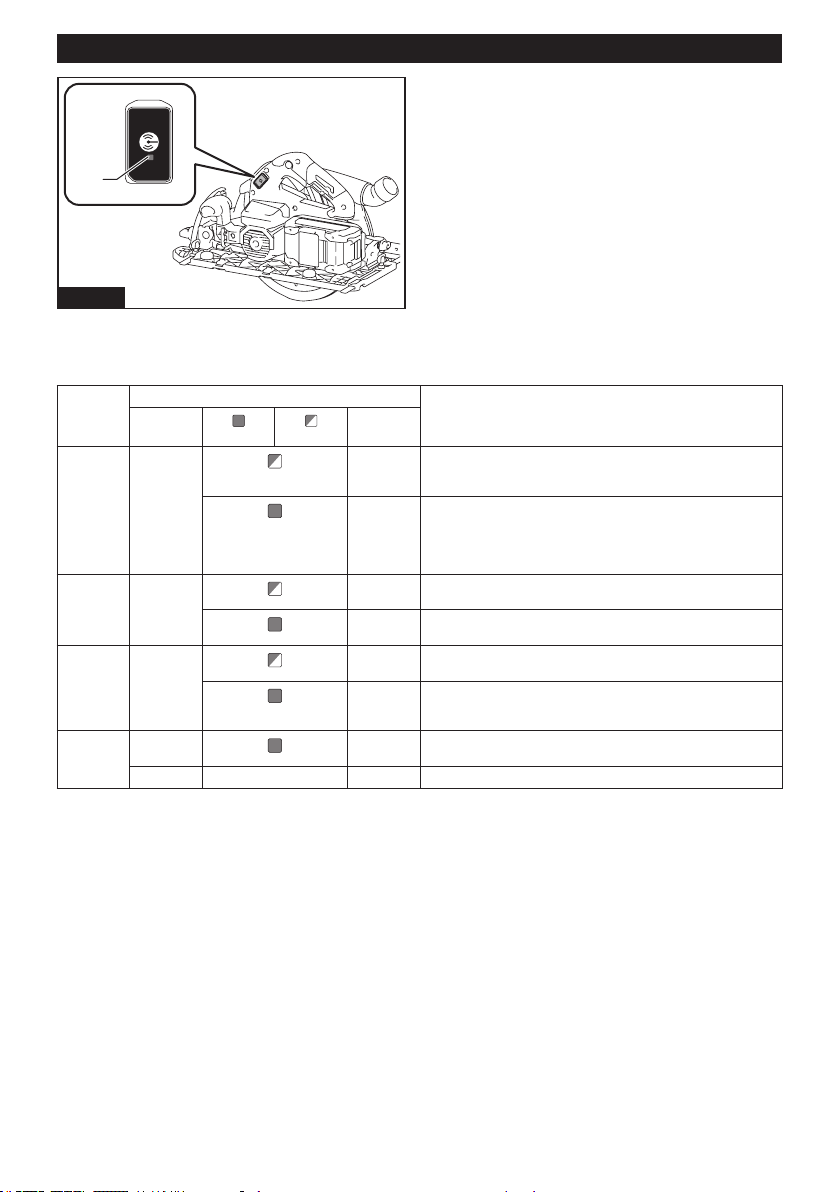
42 ESPAÑOL
Descripción del estado de la luz indicadora de activación inalámbrica
1
Fig.42
►1. Luz indicadora de activación inalámbrica
La luz indicadora de activación inalámbrica muestra el estado de la función de activación inalámbrica. Consulte la
tablaacontinuaciónparaverquésignicaelestadodelaluzindicadora.
Estado Luz indicadora de activación inalámbrica Descripción
Color
Encendida
Parpadeando
Duración
En espera Azul
2 horas La activación inalámbrica de la aspiradora está disponible. La
luz se apagará automáticamente cuando no se realice ninguna
operación durante 2 horas.
Cuando
la herra-
mienta
está fun-
cionando.
Laactivacióninalámbricadelaaspiradoraestádisponibleyla
herramienta está funcionando.
Registro
de la
herramienta
Verde
20
segundos
Ya se puede realizar el registro de la herramienta. Esperando el
registro por parte de la aspiradora.
2
segundos
El registro de la herramienta ha terminado. La luz indicadora de
activación inalámbrica comenzará a parpadear en azul.
Cancelación
del regis-
tro de la
herramienta
Rojo 20
segundos
Ya se puede cancelar el registro de la herramienta. Esperando la
cancelación por parte de la aspiradora.
2
segundos
La cancelación del registro de la herramienta ha terminado. La
luz indicadora de activación inalámbrica comenzará a parpadear
en azul.
Otros Rojo
3
segundos
Laenergíaessuministradaalaunidadinalámbricaylafunción
de activación inalámbrica está arrancando.
Apagada - - La activación inalámbrica de la aspiradora se ha detenido.

43 ESPAÑOL
Cancelación del registro de la
herramienta para la aspiradora
Realice el siguiente procedimiento para cancelar el
registro de la herramienta para la aspiradora.
1.
Instalelasbateríasenlaaspiradorayenlaherramienta.
2. Ajusteelinterruptordemodoenesperaenlaaspi-
radora en “AUTO”.
1
Fig.43
►1. Interruptor de modo en espera
3.
Oprima el botón de activación inalámbrica en la
aspiradora durante 6 segundos. La luz indicadora de acti-
vacióninalámbricaparpadearáenverdeyluegosepondrá
enrojo.Despuésdeeso,oprimaelbotóndeactivación
inalámbrica en la herramienta de la misma manera.
1 2
1
2
Fig.44
►1. Botón de activación inalámbrica 2. Luz indica-
dora de activación inalámbrica
Si la cancelación se realiza exitosamente, las luces
indicadoras de activación inalámbrica se encenderán
enrojodurante2segundosycomenzaránaparpadear
en azul.
NOTA: Las luces indicadoras de activación inalám-
bricaterminaránparpadeandoenrojodespuésdeun
lapso de 20 segundos. Oprima el botón de activación
inalámbrica en la herramienta mientras la luz indi-
cadora de activación inalámbrica en la aspiradora
esté parpadeando. Si la luz indicadora de activación
inalámbricanoparpadeaenrojo,oprimaelbotón
deactivacióninalámbricaduranteunlapsobrevey
vuelva a mantenerlo oprimido.

44 ESPAÑOL
Detección y solución de problemas para la función de activación inalámbrica
Antesdesolicitaralgunareparación,primerorealiceunainspecciónporsucuenta.Sidetectaalgúnproblemaque
no esté explicado en el manual, no intente desensamblar la herramienta. En vez de esto, solicite la reparación a un
centro de servicio autorizado de Makita, usando siempre piezas de repuesto Makita.
Estado de la anomalía Causa probable (avería) Remedio
La luz indicadora de activación ina-
lámbrica no enciende/parpadea.
La unidad inalámbrica no está instalada
en la herramienta.
La unidad inalámbrica está instalada
incorrectamente en la herramienta.
Instale la unidad inalámbrica correctamente.
Laterminaldelaunidadinalámbricay/o
la ranura está sucia.
Retireconcuidadoelpolvoylasuciedadenla
terminaldelaunidadinalámbricaylimpielaranura.
El botón de activación inalámbrica en la
herramienta no se ha oprimido.
Oprima el botón de activación inalámbrica en la
herramienta durante un lapso breve.
El interruptor de modo en espera en la
aspiradoranoestáajustadoen“AUTO”.
Ajusteelinterruptordemodoenesperaenla
aspiradora en “AUTO”.
Nohaysuministrodeenergía. Suministreenergíaalaherramientayala
aspiradora.
No se puede terminar/cancelar
el registro de la herramienta
exitosamente.
La unidad inalámbrica no está instalada
en la herramienta.
La unidad inalámbrica está instalada
incorrectamente en la herramienta.
Instale la unidad inalámbrica correctamente.
Laterminaldelaunidadinalámbricay/o
la ranura está sucia.
Retireconcuidadoelpolvoylasuciedadenla
terminaldelaunidadinalámbricaylimpielaranura.
El interruptor de modo en espera en la
aspiradoranoestáajustadoen“AUTO”.
Ajusteelinterruptordemodoenesperaenla
aspiradora en “AUTO”.
Nohaysuministrodeenergía. Suministreenergíaalaherramientayala
aspiradora.
Operación incorrecta Oprima el botón de activación inalámbrica durante
unlapsobreveyrealicelosprocedimientosde
registro/cancelación de la herramienta nuevamente.
Laherramientaylaaspiradoraestán
lejosunadelaotra(fueradelrangode
transmisión).
Acerque más la herramienta a la aspiradora. La
distancia máxima de transmisión es de aproxima-
damente 10 m, pero puede variar en función de las
circunstancias.
Antes de terminar el registro/cancela-
ción de la herramienta;
- el gatillo interruptor en la herramienta
sehajalado;o
- el botón de encendido en la aspira-
dora está activado.
Oprima el botón de activación inalámbrica durante
unlapsobreveyrealicelosprocedimientosde
registro/cancelación de la herramienta nuevamente.
Los procedimientos de registro para
la herramienta o aspiradora no se han
terminado.
Realice los procedimientos de registro tanto para
la herramienta como para la aspiradora al mismo
tiempo.
La perturbación radioeléctrica generada
por otros aparatos que emiten ondas de
radio de alta intensidad.
Mantengalaherramientaylaaspiradoralejosde
aparatostalescomodispositivosWi-Fiyhornosde
microondas.
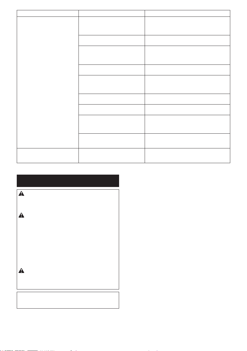
45 ESPAÑOL
Estado de la anomalía Causa probable (avería) Remedio
Laaspiradoranofuncionajuntocon
el interruptor de la herramienta.
La unidad inalámbrica no está instalada
en la herramienta.
La unidad inalámbrica está instalada
incorrectamente en la herramienta.
Instale la unidad inalámbrica correctamente.
Laterminaldelaunidadinalámbricay/o
la ranura está sucia.
Retireconcuidadoelpolvoylasuciedadenla
terminaldelaunidadinalámbricaylimpielaranura.
El botón de activación inalámbrica en la
herramienta no se ha oprimido.
Oprima el botón de activación inalámbrica durante
unlapsobreveyasegúresedequelaluzindicadora
de activación inalámbrica esté parpadeando en
azul.
El interruptor de modo en espera en la
aspiradoranoestáajustadoen“AUTO”.
Ajusteelinterruptordemodoenesperaenla
aspiradora en “AUTO”.
Más de 10 herramientas están registra-
das en la aspiradora.
Vuelva a realizar el registro de la herramienta.
Si más de 10 herramientas están registradas en la
aspiradora, la herramienta registrada al principio se
cancelará automáticamente.
La aspiradora borró todos los registros
de la herramienta.
Vuelva a realizar el registro de la herramienta.
Nohaysuministrodeenergía. Suministreenergíaalaherramientayala
aspiradora.
Laherramientaylaaspiradoraestán
lejosunadelaotra(fueradelrangode
transmisión).
Acerque más la herramienta a la aspiradora. La
distancia máxima de transmisión es de aproxima-
damente 10 m, pero puede variar en función de las
circunstancias.
La perturbación radioeléctrica generada
por otros aparatos que emiten ondas de
radio de alta intensidad.
Mantengalaherramientaylaaspiradoralejosde
aparatostalescomodispositivosWi-Fiyhornosde
microondas.
La aspiradora funciona aun cuando
el gatillo interruptor de la herra-
mientanohasidojalado.
Otros usuarios están usando la activa-
ción inalámbrica de la aspiradora con
sus herramientas.
Apague el botón de activación inalámbrica de las
demás herramientas o cancele el registro de dichas
herramientas.
MANTENIMIENTO
PRECAUCIÓN: Asegúrese siempre de que la
herramienta esté apagada y el cartucho de batería
extraído antes de intentar realizar una inspección
o mantenimiento.
PRECAUCIÓN: Limpie los protectores supe-
rior e inferior para asegurar que no haya aserrín
acumulado que pueda impedir la operación del
sistema de protección inferior. Un sistema de
protección sucio puede que limite la operación ade-
cuada,locualpodríaresultarengraveslesionesal
operador.Laformamásecazdelograrestoeslim-
piando con aire comprimido. Si el polvo está siendo
eliminado soplando aire contra los protectores,
asegúrese de usar protección respiratoria y para
los ojos adecuada.
PRECAUCIÓN: Después de cada uso, limpie
el aserrín de la herramienta.Elaserrínnopuede
entrarenlaherramientayocasionarfallasenel
funcionamiento o un incendio.
AVISO: Nunca use gasolina, bencina, diluyente
(tíner), alcohol o sustancias similares. Puede que
esto ocasione grietas o descoloramiento.
ParamantenerlaSEGURIDADyFIABILIDADdelpro-
ducto,lasreparaciones,ycualquierotratareademan-
tenimientooajustedeberánserrealizadasencentros
de servicio autorizados o de fábrica Makita, empleando
siempre repuestos Makita.
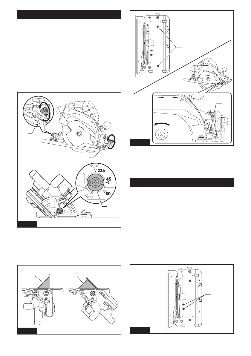
46 ESPAÑOL
Ajuste de la precisión del corte a 0° o 45°
AVISO:
No emplee las palancas para el ángulo de
bisel a -1° cuando ajuste la precisión de corte a 0°.
AVISO: No emplee el tope de seguridad para
un ángulo de bisel a 22,5° o 60° cuando ajuste la
precisión del corte a 45°.
Esteajustehasidoefectuadodefábrica.Peroencaso
dehaberseperdido,ustedpuedeajustarlosiguiendoel
procedimiento a continuación.
1.
Aojelostornillosdejaciónenlapartedelanteraytra-
sera de la herramienta, de manera que el ángulo de bisel pueda
cambiarse.Fijeeltopedeseguridadaunaposicióndelángulo
debiselde45°sivaaajustarlaprecisióndelcortea45°.
1
1
2
Fig.45
►1.Tornillodejación2. Tope de seguridad
2. Haga que la base quede perpendicular o a 45° al
disco de la sierra circular usando una regla triangular
girandoeltornillodeajusteconunallavehexagonal.
Tambiénpuedeusarunaescuadraparaajustarel
ángulo a 0°.
1 1
Fig.46
►1. Regla triangular
1
2
Fig.47
►1.Tornillodeajusteparaánguloa0°2. Tornillo de
ajusteparaánguloa45°
3. Aprietelostornillosdejación,yluegohagaun
cortedepruebaparavericarquesehayaobtenidoel
ángulo deseado.
Ajuste de la guía de profundidad
Silabasenosedeslizahaciaarribaohaciaabajocon
suavidad,esposiblequelaguíadeprofundidadse
hayainclinado.Ustedpuedeajustarlaguíadeprofundi-
dad de la siguiente manera:
1. Pongalabasedemaneraperpendicularyajuste
la profundidad de corte a la más profunda.
2. Aojelostornillosdeajusteparalaguíade
profundidad.
Laguíadeprofundidadajustasuposiciónde
manera automática.
3. Aprietelostornillosdeajusteparalaguíade
profundidad.
4. Consultelaseccióndeparalelismoparaelajuste
del mismo.
1
Fig.48
►1.Tornillosdeajusteparalaguíadeprofundidad
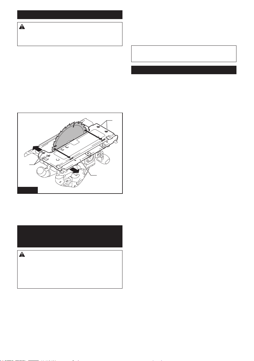
47 ESPAÑOL
Ajuste del paralelismo
PRECAUCIÓN: Mantenga el paralelismo
exacto. De lo contrario, el disco de la sierra circular
puedemorderelcarrilguía,elcualsiestádañado
puede causar una lesión.
Esteajustehasidoefectuadodefábrica.Peroencaso
dehaberseperdido,ustedpuedeajustarlosiguiendoel
procedimiento a continuación.
1. Coloque la herramienta a la profundidad de corte
máxima.
2. Asegúresedequetodaslaspalancasytornillos
estén apretados.
3. Aojelostornillosmostradosenlailustración.
4. Mientras abre el protector inferior, mueva la parte
traseradelabasedemaneraquelasdistanciasAyB
sean iguales.
1
1
2
A
B
Fig.49
►1. Tornillo 2. Base
5. Aprietelostornillosyhagauncortedeprueba
paravericarelparalelismo.
ACCESORIOS
OPCIONALES
PRECAUCIÓN: Estos accesorios o aditamen-
tos están recomendados para utilizarse con su
herramienta Makita especicada en este manual.
El empleo de cualquier otro accesorio o aditamento
puede conllevar el riesgo de lesiones personales.
Utilice los accesorios o aditamentos solamente para
sunestablecido.
Sinecesitacualquierayudaparamásdetallesen
relación con estos accesorios, pregunte a su centro de
servicio local Makita.
• Disco de la sierra circular
• Base inferior
• Carrilguía
• Guíadebisel
• Pinza
• Hoja
• Hojadehule
• Hojadeposición
• Llave Allen (hexagonal)
• Boca delantera de 24
• Unidad inalámbrica
• BateríaycargadororiginalesdeMakita
NOTA:Algunosdelosartículosenlalistapueden
incluirse en el paquete de la herramienta como acce-
soriosestándar.Éstospuedenvariardepaísapaís.
GARANTÍA LIMITADA DE MAKITA
Ésta Garantía no aplica para México
Consultelahojadelagarantíaanexaparaverlos
términosmásvigentesdelagarantíaaplicableaeste
producto.Encasodenodisponerdeestahojade
garantíaanexa,consultelosdetallessobrelagarantía
descritosenelsitiowebdesupaísrespectivoindicado
a continuación.
Estados Unidos de América: www.makitatools.com
Canadá: www.makita.ca
Otrospaíses:www.makita.com

Some dust created by power sanding, sawing, grinding, drilling, and other
construction activities contains chemicals known to the State of California
to cause cancer, birth defects or other reproductive harm. Some examples
of these chemicals are:
• lead from lead-based paints,
• crystalline silica from bricks and cement and other masonry products, and
• arsenic and chromium from chemically-treated lumber.
Your risk from these exposures varies, depending on how often you do this
type of work. To reduce your exposure to these chemicals: work in a well
ventilated area, and work with approved safety equipment, such as those
dust masks that are specially designed to filter out microscopic particles.
WARNING
< USA only >
ADVERTENCIA
Algunos polvos creados por el lijado, aserrado, esmerilado, taladrado y
otras actividades de la construcción contienen sustancias químicas
reconocidas por el Estado de California como causantes de cáncer, defectos
de nacimiento y otros peligros de reproducción. Algunos ejemplos de estos
productos químicos son:
• plomo de pinturas a base de plomo,
• sílice cristalino de ladrillos y cemento y otros productos de albañilería, y
• arsénico y cromo de maderas tratadas químicamente.
El riesgo al que se expone varía, dependiendo de la frecuencia con la que
realice este tipo de trabajo. Para reducir la exposición a estos productos
químicos: trabaje en un área bien ventilada y póngase el equipo de seguridad
indicado, tal como las máscaras contra polvo que están especialmente
diseñadas para filtrar partículas microscópicas.
< Sólo en los Estados Unidos >
Makita Corporation
3-11-8, Sumiyoshi-cho,
Anjo, Aichi 446-8502 Japan
www.makita.com
885933-945
GSH03-1
EN, ESMX
20210825