1/22 Rev. F 171375
2
1/22 Rev. F 171375
3
4-5
Receiving Information 4
Safety Information 4
6-12
Set-Up and Installation 6
Start Up and Operation 7
Temperature Adjustment 7
Standard Temperature (Cooler) Systems 7
Low Temperature (Freezer) Systems 7
Loading Product 9
Diuser Installation Instructions 9
Optional Feature – Electronic Condensate Vaporizor 10
Locating and Mounting Condensing Units 11
12-13
14
15
1/22 Rev. F 171375
3

4
1/22 Rev. F 171375
Congratulations on your purchase of a quality-built refrigeration system. When properly installed and maintained,
this product will give many years of trouble-free service. It was shipped using trusted carriers with a history of
careful handling, good customer service and prompt delivery.
Even with all of these precautions, occasionally accidents may happen which result in shipping damage. When
the product is picked up by the carrier, they assume responsibility for the product until they deliver it to you. Thus,
any claims for shipping damages must be filed with the delivering carrier.
Always thoroughly inspect the delivery for visible damages and shortages. Should any damages or shortages be
found, be sure to note them in detail on the delivery receipt before you sign it. Make sure the driver signs and
dates the delivery receipt acknowledging the damages. This is critical in protecting yourself should a claim need
to be filed. Consult the carrier’s website for their specific claim procedures. Remember, it is your responsibility to
file a claim with the carrier.
In the case of concealed damages that are not discovered in the initial inspection but are found upon removing
packaging, time is critical. You should unpack and inspect the unit as soon as possible. If concealed damage is
found, stop unpacking and contact the delivering carrier immediately to alert them of the damages and get a claim
number. Save all packaging for inspection by the carrier. Consult the carrier website for details in filing a concealed
damage claim.
Please remember, the carrier is your only source for reclaiming freight damages. The manufacturer should not be
contacted to attempt a return of the product. No returns are accepted without a prior authorization
This manual may contain notices that identify situations that could cause death, serious injury and /or damage to
the appliance or property.
Please make note of the following definitions;
Indicates a hazardous situation which could result in death or serious injury.
Indicates a situation which could result in damage to the appliance or property.
Indicates important information about the use and care of the appliance.
This appliance should be applied only for the use for which it has been expressly intended. Any other use would be
considered improper and therefore dangerous. The manufacturer cannot be held responsible for injury or damage
resulting from improper, incorrect and unreasonable use. Failures to install, operate, or maintain the appliance
in accordance with this manual will adversely affect safety, performance, component life and warranty coverage.
To reduce the risk of death, electric shock, serious injury or fire, follow basic precautions including but not limited
to the following:
• Only qualified service technicians should install and service this appliance.
• This appliance must be installed in accordance with applicable national, state and local codes and regulations.
• To reduce the risk of electrical shock, do not touch the appliance or plug with wet hands.
• Disconnect the appliance from power before servicing.
• The appliance requires an independent power supply of proper capacity that matches the power cord plug

1/22 Rev. F 171375
5
supplied. See the appliance nameplate for electrical specifications. Failure to use an independent power supply
of proper capacity can result in a tripped breaker, blown fuse, damage to existing wiring or component failure.
This could lead to heat generation or fire.
• The appliance must be properly grounded. This appliance is equipped with a NEMA 5-15P, 6-15P or 6-20P three
prong grounded plug to reduce the risk of potential electrical shock hazards. It must be connected to a properly
grounded, independent 3 prong wall outlet. Do not remove the ground prong from the appliance plug and do not
use and adapter plug. Failure to follow these instructions may result in death, electrical shock or fire.
• Do not use an extension cord to supply power to the appliance.
• Do not use the appliance should the power cord become damaged. The power cord should not be altered,
jerked, pinched, bundled and/or used to hang objects from. Such actions could result in electrical shock or fire.
To disconnect the unit from power, be sure to grasp and pull on the plug, not the cord.
• Should the power cord require replacement or service, use only the manufactures replacement parts and be
sure to connect the green ground wire to the appliance in the same manner the original wire was connected.
• Do not spray or splash water on the appliance as this may cause short circuits, electrical shock, corrosion or
failure.
• Do not make alterations or modifications to the appliance as these could result in electric shock, injury, fire or
damage to the appliance.
• Children must be properly supervised around this appliance.
• This appliance is not intended for use by persons (including children) with reduced physical, sensory or mental
capabilities or lack of experience and knowledge unless they have been given supervision or instruction
concerning its use by a person responsible for their safety.
• Do not climb, stand, or hang on or into the appliance or its components. Death or serious injury could occur or
the appliance could be damaged.
• Use caution when opening doors or lids and keep fingers out of pinch points areas.
• Do not use combustible sprays or aerosols around the appliance as they may catch fire.
• Do not store gasoline or other flammable substances in or near the appliance as they may catch fire.
• Keep the area around the appliance clean. Dirt, dust or insects around the appliance could cause harm to
individuals or damage to the equipment.
• Do not block air inlets or outlets as this would cause cooling performance to be reduced.
• Do not overload the storage capacity of the appliance. Allow space between stored items for air flow.
• Do not load warm or hot items into the appliance. Allow them to cool first or they will raise the cabinet temperature
and could hasten the deterioration of other foods stored in the cabinet.
• This appliance is designed for the temporary storage to food products. Use proper sanitation practices.
• All food products should be covered or stored in sealed containers. Open foods may dry up, pass their smell to
other foods and increase cross contamination. Some food products may accelerate corrosion of the evaporator
resulting in failure of the appliance to cool.
• Component parts must be replaced with manufacturer original equipment parts.
• The appliance requires an independent power supply of proper capacity that matches the power cord plug
supplied. See the appliance nameplate for electrical specifications. Failure to use an independent power supply
of proper capacity can result in a tripped breaker, blown fuse, damage to existing wiring or component failure.
This could lead to heat generation or fire.

6
1/22 Rev. F 171375
This appliance must be installed in accordance with all applicable national, state and local regulations. This
appliance is heavy. Use care when lifting and positioning. Work in teams when needed to prevent injury or
damage. The store temperature should be at or below 90°F and a relative humidity of 55% or less for indoor
installations. At higher temperature or humidity conditions, the performance of these cases may be affected and
the capacity diminished. These cases should not be positioned where it is directly exposed to rays of sun or near
a direct source of radiant heat or airflow. This will adversely affect the case and will result in reduced performance.
Operating this appliance outside its range and installation requirements may affect performance and warranty
coverage.
Locating the Appliance
This system requires open air space around it to operate properly. A minimum of 4” above the unit and 24" on all
sides is required to operate. Allow space for heated discharge air to escape and a fresh air intake supply.
• Confirm that the ambient temperatures are within the tolerances allowed.
• Do not locate next to heat generating appliances.
• Confirm the unit is installed level.
• Do not use an extension cord to connect the unit to power. Use of an extension cord will void all warranties.
• Do not tamper with the ground pin on the power cord and confirm that the power receptacle has a properly
wired ground connection.
• The system must be isolated on a power circuit.
• Confirm that the power supply matches the required power supply noted on the cabinet serial plate.
This section has the general instructions for installing the ceiling mounted self-contained refrigeration system.
Note:
• Proper "temporary" support of the ceiling panel with the cut out must be added during the installation of the
refrigeration.
• Due to the weight of these systems (approximately 200 lbs.), it is highly recommended that proper lifting
equipment, such as a fork lift or material lift, be utilized during installation. Be sure to allow for sufficient airflow
around the condenser. A 4" minimum clearance is required above the unit with at least 24" clear space on
all sides. If multiple units are located in the same area, be sure they do not exhaust hot air into one another.
Refer to section titled "Locating and Mounting Condensing Units" for details. In addition to allowing for proper
airflow, consideration should be given to the final mounting location of the refrigeration system relative to the
customer location to avoid any possible risk of noise impacting the customer experience.
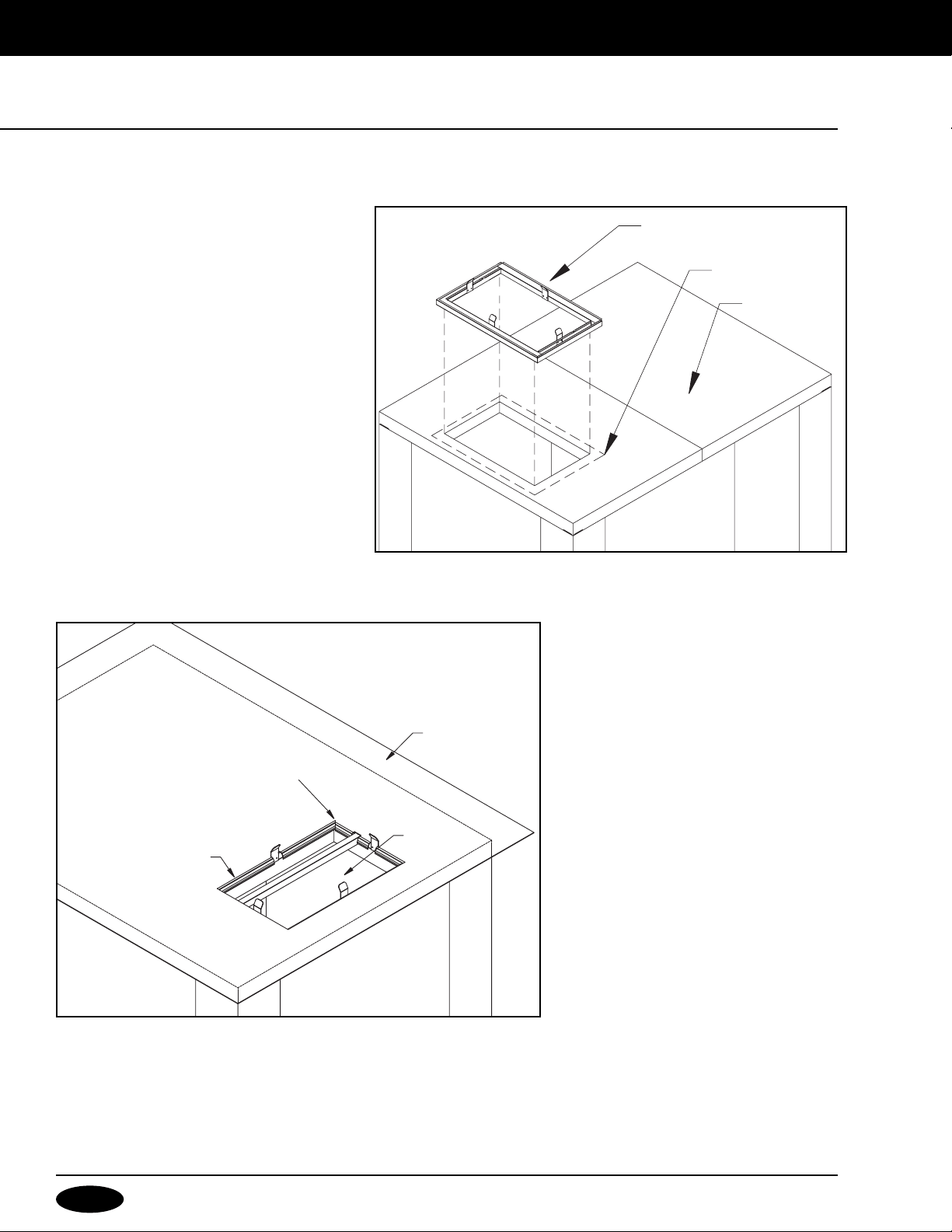
Position the insulated evaporator section of the Refrigeration System over the hole in the walk-in ceiling section.
Special care should be used when positioning the evaporator section over the ceiling cut-out. Be sure not to
damage the gasket underneath the evaporator section.
Fasten latches and seal perimeter as described in the Latch and Diffuser Installation Instructions found on pages
9 and 10.
Some adjustment may be required by simply bending the ceiling section divider slightly
forward or backward. This will prevent any short cycling of discharge and return air.

1/22 Rev. F 171375
7
After meeting the set-up and installation requirements the unit is ready to start-up. Once the power cord is
connected to a live outlet and the power switch is in the “on” position the unit will start running. Allow the unit to
run for two (2) hours and verify the walk-in is down to temperature prior to loading with product.
These units come equipped with an electronic controller system. The Temperature Control display and operator
interface is located on the front of the unit and comes pre-set to give walk-in air temperatures of approximately
+37ºF for coolers or -10°F for freezers. Refer to the accompanying electronic controller manual for detailed
instructions on adjusting the controller settings.
The electronic controller system is a highly efficient electronic controller that regulates an electronic expansion
valve in response to evaporator superheat and return air temperature, featuring demand defrost fan control
technology. This system will operate differently from previous system you may have worked with in the past. Refer
to the controller instructions supplied with the unit for additional information.
Important: It is the installing contractor’s responsibility to check the operation upon start-up and make necessary
temperature adjustments as required for proper operation.
Note: Capsule Pak Refrigeration Systems that are designed for outdoor installation will be fitted with electric
crankcase heaters and automatic head pressure control valves.
Refrigeration Controller
Capsule Pak refrigeration systems are equipped with an electronic controller system. See separate instructions on
the operation of this electronic temperature control.
Defrost Cycle (Cooler System)
The electronic controller uses an automatic on-demand defrost algorithm that eliminates unnecessary defrosts
typically associated with time-based alternatives which reduces energy consumption.
The low temperature, automatic electric defrost Capsule Pak refrigeration system utilizes the electronic controller
with a programmable set point and a preset algorithm to cycle the fans and compressor in order to maintain a
tighter room temperature.
Important: It is the installing contractor’s responsibility to check the operation upon start-up and make necessary
temperature control adjustments as required for proper operation.
Note: Capsule Pak Refrigeration Systems that are designed for outdoor installation will be fitted with electric
crankcase heaters, electrically heated condensate drain tubes, automatic head pressure control valve, and the
"pump-down cycle".
Defrost Cycle
The electronic controller uses an automatic or demand defrost algorithm that eliminates unnecessary defrosts
typically associated with time based alternatives which reduces energy consumption. For additional information
see the controller instructions supplied with the refrigeration system.

8
1/22 Rev. F 171375
Defrost Cycle Termination
The electronic controller will run the coil heater until the coil is above 32°F. At this point it will work very different
than a traditional defrost cycle. The heaters will pulse on and off allowing the heat to radiate through the coil until
both coil sensing probes reach 50°F or 30 minutes whichever happens first. The fan(s) in the evaporator housing
will not start, however, until the fan delay cycle has expired. See the "Fan Delay" below.
Fan Delay
When a defrost cycle is terminated the evaporator fan(s) will not start until the evaporator coil temperature is
reduced to about +30°F. Once this temperature is reached, the fan delay cycle will turn the fans back on continuing
the refrigeration cycle.
The fan delay feature is an important part of defrosting. If the fan(s) was permitted to start immediately following
a defrost period, the heat that accumulated in the evaporator housing would be circulated throughout the walk-in,
raising the temperature considerably. In addition, any droplets of moisture that remained clinging to the fins of the
evaporator coil would be blown into the storage space. The fan delay feature provides for a short refrigeration cycle
WITHOUT the evaporator fan(s) to prevent these conditions.
Note: During the initial startup of a Capsule Pak Refrigeration System on warm walk-in, the evaporator fan(s) will
not start until the evaporator coil reaches +30°F. Further, the evaporator fans may cycle "on" and "off" several times
until the evaporator coil reaches and maintains +30°F.
Drain Tube Heater
Low temperature ceiling mounted Capsule Pak refrigeration systems employ a low wattage, electric heater
wire. This heater is spirally wound around the condensate drain tube that extends from the drain pan below the
evaporator through the Capsule Pak evaporator section housing wall. This heater is energized continually to allow
the free flow of the condensate water to the outside of the evaporator section.
Medium temperatures mounted Capsule Pak employ the same condensate drain tube that extends from the drain
pan below the evaporator through the Capsule Pak evaporator section housing wall but has no heater wire.
Drainage of Condensate Water
Indoor Models
On indoor self-contained Capsule Pak systems, the condensate drain tube is factory plumbed to discharge
the condensate water into an evaporative drain pan located under the compressor in the condensing unit. The
compressor discharge line is routed inside this pan to heat the condensate water to aid evaporation.
In locations where high moisture content exists, it is possible that the evaporative drain pan may overflow. In this
case the drain line must be plumbed to an optional electric condensate pan evaporator (part number 133141 or
132962).
Outdoor Models
On outdoor self-contained Capsule Pak systems, the condensate drain line must be plumbed by the installer. The
installer will need to provide a drain line connected to the drain tube exiting the evaporator section, route it thru
the provided knock-out holes on either side of the Capsule Pak system, wrap the line with suitable heater wire and
insulation if subject to below freezing temperatures and install a P-trap at the termination. The line can flow to an
optional condensate evaporator pan or to a drain.
1/22 Rev. F 171375
9
Once that cabinet has been operating at the desired temperature for a sufficient period of time, product can be
loaded into the cabinet.
• When loading product use caution not to block airflow to achieve maximum cooling performance.
• Do not load product where it would block the air intake or discharge at the back inside wall of the cabinet.
• Do not load warm product into the cabinet as it will affect the cabinet temperature and products previously
stored in the cabinet.
• Products should be in covered containers or wrapped to prevent cross contamination.
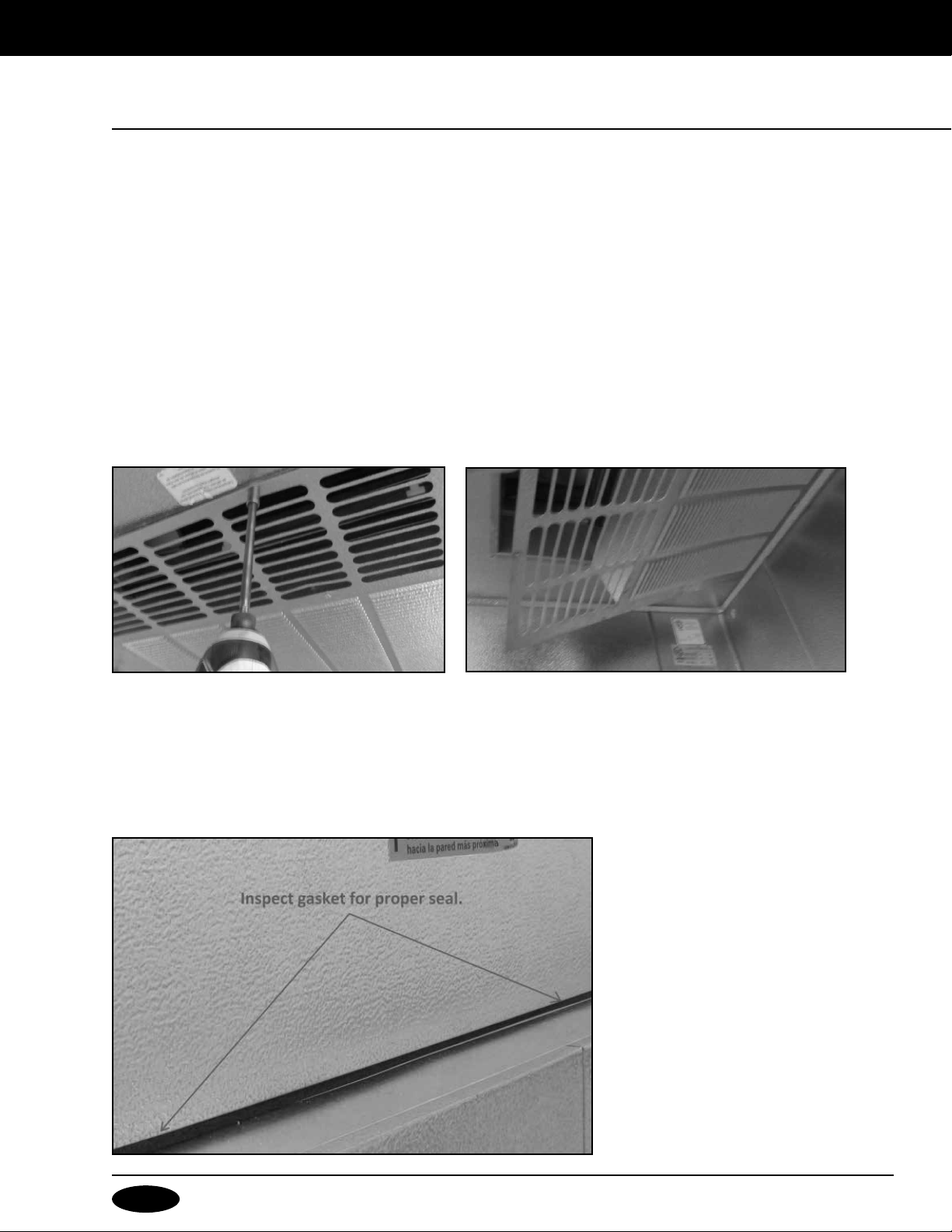
1. Remove diffuser from ceiling panel before installing ceiling panel (Figures 1 and 2)
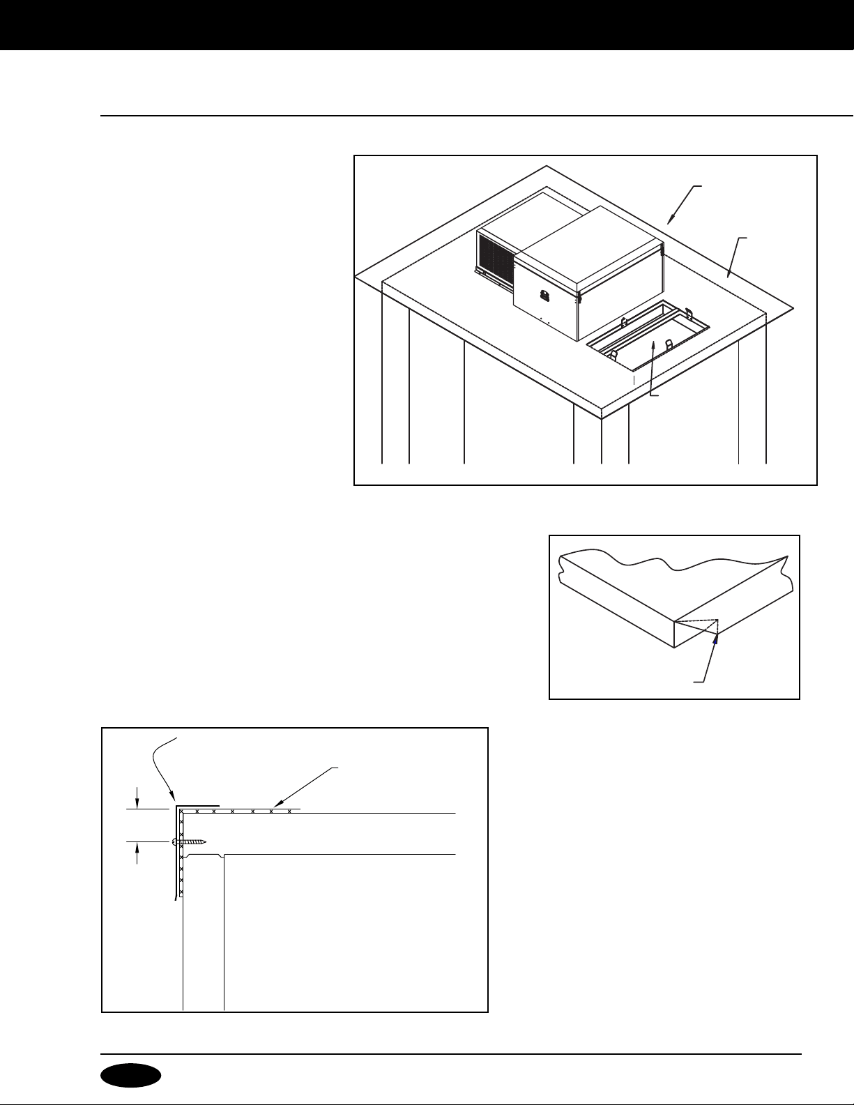
2. Lift Capsule Pak into position on top of walk-in. Note: Do not slide Capsule Pak into position as cowl gasket
damage will occur. If the Capsule Pak™ must be slid into position, place Capsule Pak on a piece of cardboard
prior to moving to prevent gasket damage.
3. Inspect cowl gasket to ensure proper placement (Figure 3)
10
1/22 Rev. F 171375
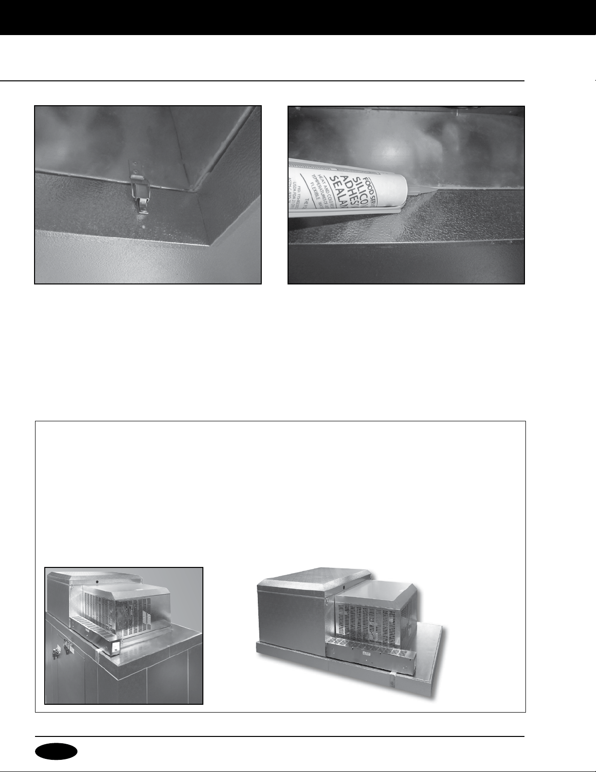
4. Secure interior latches (Figure 4)
5. Seal cowl to ceiling at gasket seam above diffuser panel using provided silicone (Figure 5)
6. Replace diffuser panel removed in step 1.
Some adjustment may be required by simply bending the ceiling section divider slightly forward or
backward. This will prevent any short cycling of discharge and return air.
The vaporizer is intended to be mounted in the orientation shown below. Note the location of the condensate
drain coming from the evaporator and locate the vaporizer so the condensate water will drain into it. Use the
supplied plastic tubing and copper elbow and extend the drain into the vaporizer. Cut the plastic tubing to the
desired length.
Provide power to the electric vaporizer per local national electrical codes. Avoid locating vaporizer below any
electrical enclosures.
1/22 Rev. F 171375
11
Condensing units (CU’s) must be located where there is an unrestricted supply of clean, fresh air. Do not locate
units where air discharge from one will enter into the air intake of others nor where the air flow is toward a wall or
obstruction. Avoid locating units in restricted spaces where heat will build up and can enter the condenser. There
must be room around the unit for regular inspection and service. We recommend 200CFM in any area where
condensing units may be located. Air flow should be sufficient to maintain an ambient temperature of no more
than 90°F.
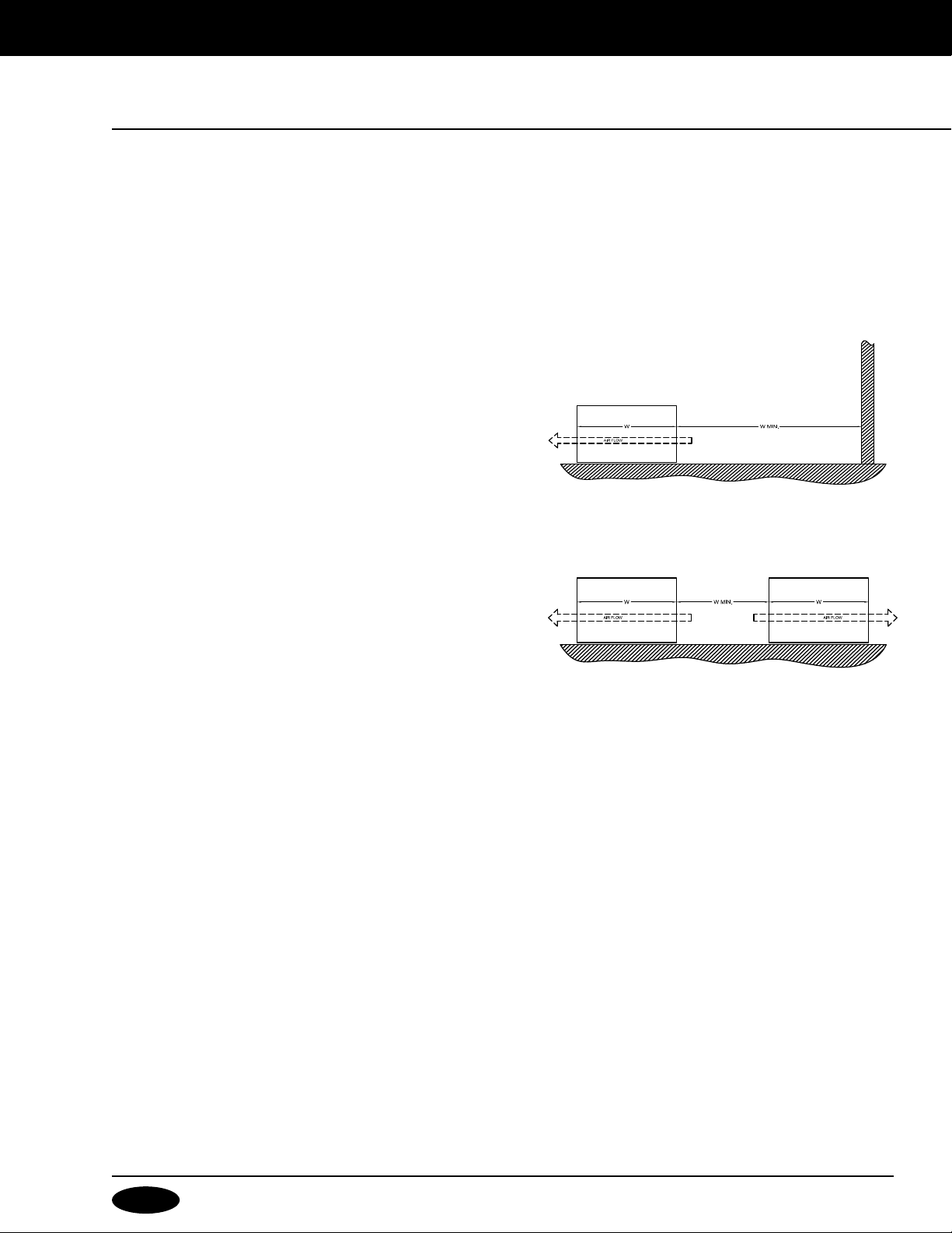
Walls or Obstructions
The units should be located so that air may circulate freely.
For proper air flow, all sides of the unit should be a minimum
of the width of the condensing unit away from any wall or
obstruction. It is preferred that this distance be increased
whenever possible.
Multiple units
For units placed side by side, the minimum distance between
units should be the width of the largest unit. If units are placed
end to end, the minimum distance between units should be
4 feet.
Roof mounted condensing units must have adequate support
for their operating weight. Corrosive atmospheres require
custom design condensers.
Condensing Unit
Walk-in Ceiling
Building Wall
Walk-in Ceiling
Condensing Unit Condensing Unit
12
1/22 Rev. F 171375
. After the walk-in is completely
assembled, place the curb face down
on top of the ceiling sections (curb is
fastened to crate base during shipping
and must be removed and installed
prior to membrance roof installation). To
ensure proper opening alignment, mark
the outside portion of the curb on the
ceiling sections with a marking pencil
. Remove the paper from the gasket and
position the curb, gasket side down, on
the pencil line. Press down firmly. Note:
Movement of the curb is very difficult
after the gasket adheres to the ceiling
section. Refer to Figure 1.
. Lay the membrane roofing material
over the walk-in ceiling sections and
curb leaving a six inch overhang
on all four sides of the walk-in.
Using an utility knife, cut a hole in
the membrane roof approximately
1-1/2” in from the edge of the
opening. (The resulting hole in the
membrane will be smaller than the
ceiling opening). Fold the 1-1/2”
membrane flaps into the opening,
notching the membrane around
the locators and divider. Use either
sheet metal screws, caulk, glue,
etc. to fasten the membrane roofing
material to the inside edge of the
curb frame. Refer to Figure 2. Do
not make any penetrations in the top
of the membrane roof. Any needed
penetrations should be through the
side wall to maintain the integrity of
the roof.
Curb
Alignment Marks
Ceiling Sections
Walk-In
Membrane
Roofing
Opening
Fasten to Edge
of Curb Frame
Cutout Line
Walk-In
1/22 Rev. F 171375
13
4. Set the Refrigeration System over the
opening in the curb. Remove Diffuser
Panel from the ceiling inside the
walk-in to gain access to four latches
located along the inner perimeter of the
cowl. Refer to the Latch and Diffuser
Installation Instructions found on pages
8-9. Use the Lock Extensions supplied
with the curb to bridge the distance
between the latches and strikes. Seal
the latched seam as described in the
instructions. When reinstalling the
Diffuser Panel, make sure that the
ceiling section divider located on the
panel seals against the black gasket.
Some adjustment may be required
by simply bending the ceiling section
divider slightly forward or backward.
This will prevent any short cycling of
discharge and return air.
Before proceeding to step 5, pull
membrane straight and smooth before
installing the trim.
Note: Seal gasket at top of curb with silicone.
. Fold all four corners of the membrane roofing material over the walk-in
corners as shown in Figure 4.
6. Attach the trim and door hood (if your walk-in is equipped with them)
by using the provided pan head sheet metal screws. Ensure the trim
and membrane roof material cover the joint between the ceiling and
wall panels. Refer to figure 5. Note: The trim may have to be cut to fit.
7. Trim off all excess membrane roofing
material from under the trim with a utility knife.
Do not allow the knife to cut the metal panel,
as this will damage the coating and cause rust.
In outdoor installations, the condensate
line should be plumbed to the nearest drain
and a P-trap installed near the end. Check
local building codes. Outside drain lines must
also be wrapped with a suitable heater wire
and insulated if they are ever subjected to
below freezing temperatures.
Fold Membrane
Capsule Pak™
Membrane
Roofing
Opening
Walk-In
Ceiling Panel
Membrane Roof
Material
Trim by Nor-Lake/Master-Bilt
3"

14
1/22 Rev. F 171375
MAINTENANCE
:
The condensing unit is accessible by removing the condensing unit housing. The evaporator coil section is
accessible by unlatching and removing the evaporator section housing cover.
The efficiency of the refrigeration system, to a great extent, depends upon the unrestricted f.flow of air through the
condenser and evaporator coils. For this reason both coils should be as clean as possible at all times and should
have an unrestricted supply of air.
A vacuum cleaner with a bristle attachment can be used to clean the coil. If debris on the coil cannot be removed
easily, a bristle brush can be used to loosen it by gently brushing in the same direction as the fins so as not
to damage them and restrict air flow. An air compressor can be used to clean the condenser coil also. The air
flow should be directed through the coil from the fan motor side. A damp hand towel can be blocked against the
opposite side so that the majority of the dust will be captured in the towel minimizing the mess in the room.
Condensate from the evaporator pan is discharged into a hot gas vaporizer pan, which is located in the condensing
unit housing. Here the hot discharge gas from the compressor elevates the temperature of the water and it
vaporizes into the atmosphere. This pan should be cleaned periodically to remove solids that remain after the
moisture is evaporated.

1/22 Rev. F 171375
15
MALFUNCTION POSSIBLE CAUSE SOLUTION
Compressor will not start - 1. Unplugged or power off 1. Plug in service cord or turn power on
no hum 2. Fuse blown or removed 2. Replace fuse
3. Overload tripped 3. Determine reasons and correct
4. Control stuck open 4. Repair or replace
5. Wiring incorrect 5. Check wiring against the diagram
Compressor will not start - 1. Improperly wired 1. Check wiring against the diagram
hums but trips on overload 2. Low voltage to unit 2. Determine reason and correct
protector 3. Starting capacitor defective 3. Determine reason and replace
4. Relay failing to close 4. Determine reason, correct or replace
Compressor starts and runs, 1. Low voltage to unit 1. Determine reason and correct
but short cycles on overload 2. Overload defective 2. Check current, replace overload protector
protector 3. Excessive head pressure 3. Check ventilation or restriction in
refrigeration system
4. Compressor hot — warm ambient 4. Check refrigerant charge, fix leak if
conditions necessary
Compressor operates long 1. Short of refrigerant 1. Fix leak, add charge
or continuously 2. Control contact stuck 2. Repair or replace
3. Evaporator coil iced 3. Determine cause, defrost manually
4. Restriction in refrigeration system 4. Determine location and remove restriction
5. Dirty condenser —warm ambient 5. Clean condenser
conditions
6. Warm ambient 6. Address ambient conditions
Compressor runs fine, but 1. Overload protector 1. Check wiring diagram
short cycles 2. Cold control 2. Differential too close - widen
3. Overcharge 3. Reduce charge
4. Air in system 4. Purge and recharge
5. Undercharge 5. Fix leak, add refrigerant
Starting capacitor open, 1. Relay contacts stuck 1. Clean contacts or replace relay
shorted or blown 2. Low voltage to unit 2. Determine reason and correct
3. Improper relay 3. Replace
Relay defective or burned out 1. Incorrect relay 1. Check and replace
2. Voltage too high or too low 2. Determine reason and correct
Refrigerated space too warm 1. Control setting too high 1. Reset control
2. Refrigerant overcharge 2. Purge refrigerant
3. Dirty condenser 3. Clean condenser
4. Evaporator coil iced 4. Determine reason and defrost
5. Not operating 5. Determine reason, replace if necessary
6. Air flow to condenser or 6. Remove obstruction for free air flow — no storage
evaporator blocked on top of walk-in
7. Warm ambient conditions 7. Ambient conditions should be 90° or less
Standard temperature system 1. Control setting is too low 1. Reset the control
freezes the product
Objectionable noise 1. Fan blade hitting fan shroud 1. Reform or cut away small section of shroud
2. Tubing rattle 2. Locate and reform
3. Vibrating fan blade 3. Replace fan blade
4. Condenser fan motor rattles 4. Check motor bracket mounting, tighten
5. General vibration 5. Compressor suspension bolts not loosened
on applicable models - loosen them
6. Worn fan motor bearings 6. Replace fan motor
Water overflowing from 1. Air leak between refrigeration system 1. Check that refrigeration system is properly set
evaporator drain pan or and walk-in panel. in panel opening.
condensate vaporizer pan 2. Drain line from evaporator drain 2. Clean blockage from inside of drain line.
pan to condensate vaporizer is
blocked with foreign material.
3. Drain line from evaporator drain 3. Check that drain line heater (on freezers)
pan to condensate vaporizer is is working and repair or replace as required.
blocked with ice.
4. Walk-in operating in high humidity 4. Plumb drain line from evaporator to floor
environment (heavy door usage). drain or replace high gas vaporizer with
electric vaporizer. Consult factory for further information.
16
1/22 Rev. F 171375
Refrigerated Solutions Group
891 County Road U
Hudson, WI 54016
800-955-5253 Norlake Foodservice Sales
800-477-5253 Norlake Scientic Sales
800-388-5253 Norlake Parts/Service
800-647-1284 Master-Bilt Sales
800-684-8988 Master-Bilt Parts/Service
Thank you for purchasing Norlake equipment! Please visit the
link below to complete your WARRANTY REGISTRATION.
www.norlake.com/register